ARCH 7511 PROFESSIONAL STUDIES - Unitec
ARCH 7511 PROFESSIONAL STUDIES - Unitec
ARCH 7511 PROFESSIONAL STUDIES - Unitec

You also want an ePaper? Increase the reach of your titles
YUMPU automatically turns print PDFs into web optimized ePapers that Google loves.
Faculty of Creative Industries and Business<br />
Department of Architecture<br />
Bachelor of Architectural Studies<br />
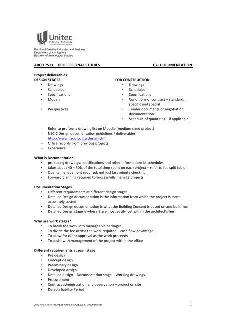
<strong>ARCH</strong> <strong>7511</strong> <strong>PROFESSIONAL</strong> <strong>STUDIES</strong> L3– DOCUMENTATION <br />
Project deliverables <br />
DESIGN STAGES <br />
FOR CONSTRUCTION <br />
• Drawings • Drawings <br />
• Schedules • Schedules <br />
• Specifications • Specifications <br />
• Models • Conditions of contract – standard, <br />
specific and special <br />
• Perspectives • Tender documents or negotiation <br />
documentation <br />
• Schedule of quantities – if applicable <br />
– Refer to proforma drawing list on Moodle (medium sized project) <br />
– NZCIC Design documentation guidelines / deliverables ; <br />
http://www.nzcic.co.nz/Design.cfm <br />
– Office records from previous projects <br />
– Experience <br />
What is Documentation <br />
• producing drawings, specifications and other information; ie schedules <br />
• takes about 40 – 50% of the total time spent on each project – refer to fee split table <br />
• Quality management required, not just last minute checking <br />
• Forward planning required to successfully manage projects <br />
Documentation Stages <br />
• Different requirements at different design stages <br />
• Detailed Design documentation is the information from which the project is most <br />
accurately costed <br />
• Detailed Design documentation is what the Building Consent is based on and built from <br />
• Detailed Design stage is where $ are most easily lost within the architect’s fee <br />
Why use work stages? <br />
• To break the work into manageable packages <br />
• To divide the fee across the work required – cash flow advantage <br />
• To allow for client approval as the work proceeds <br />
• To assist with management of the project within the office <br />
Different requirements at each stage <br />
• Pre design <br />
• Concept design <br />
• Preliminary design <br />
• Developed design <br />
• Detailed design – Documentation stage – Working drawings <br />
• Procurement <br />
• Contract administration and observation – project on site <br />
• Defects liability Period <br />
2013 <strong>ARCH</strong> <strong>7511</strong> <strong>PROFESSIONAL</strong> <strong>STUDIES</strong>, L3 - Documentation 1
New Zealand Construction Industry Council <br />
• www.nzcic.co.nz/Design.cfm -‐ Design Documentation Guidelines <br />
• Read preamble, architectural guidelines /deliverables and co-‐ordination guidelines <br />
• Defines documentation appropriate to each stage <br />
• Split into sections relevant to each consultant type <br />
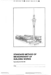
The following notes are largely drawn from -‐"Production Drawings -‐ a code of procedure for <br />
building works" published in London by the Building Project Information Committee 1987. <br />
UNITEC Library ref 692.1 PRO (M) <br />
This is an excellent and still very relevant handbook of practical advice and recommended <br />
reading. <br />
From: 1 Introduction <br />
Drawings show (inter alia) size, shape and relationships. <br />
Drawings cannot be neatly parceled into categories, e.g. roof or wall <br />
Drawing arrangement schemes need to be flexible <br />
From: 2 Coordination of information on drawings <br />
− Responsibilities of architects and other consultants (for information on drawings) needs to <br />
be spelt out in compatible agreements for services made with the Client, e.g. are structural <br />
details for a small job to go on the architect's drawings -‐ or to be separate on the Structural <br />
Engineer’s drawings? <br />
− Who checks that such details are correctly drawn? <br />
− Coordination of drawing information is a major process <br />
− Layer CAD drawings to assist with co-‐ordination <br />
From: 3 Drawing arrangement <br />
− For small to medium sized projects of simple construction there might be (say) 30 drawings <br />
in a typical set, <br />
− simple logical sequence combining layouts, details and schedules. <br />
− For a medium-‐sized project of complicated construction, or a large but simply constructed <br />
project, a set of (say) 100 drawings might be required. <br />
− LAC system – ‘location’ drawings, schedules, ‘assembly’ drawings and <br />
‘component’ drawings. <br />
− For a large project of complicated construction, with (say) >250 drawings in the set <br />
− subdivision of the building(s) into parts, (each with its own set of location, <br />
assembly and component drawings and schedules) <br />
From: 3.4 Types of drawing arrangement <br />
− Group by office of origin ie separating the drawings produced by architects, structural <br />
engineers, services engineers and other specialists (and sometimes giving each group a <br />
distinctive code, such as A, S, M, E). <br />
− Grouping by type of information, at its simplest, separates <br />
− plans/elevations/sections <br />
− schedules <br />
− details, <br />
− Grouping by Location, Assembly and Component – LAC’s <br />
− Grouping by parts of the building, ie (say) foundations, drainage, walls, roof -‐ Components <br />
− Grouping by contractor is another possibility, (particularly applicable to "Fast Track" and <br />
"Managed” projects, where tenders are often called for separate "packages" of work -‐ often, <br />
but not always, reflecting a trade breakdown of the work. ) <br />
− Grouping by location separates the project into "zones or "blocks on plan <br />
− CIS/fB classification system not used these days <br />
2013 <strong>ARCH</strong> <strong>7511</strong> <strong>PROFESSIONAL</strong> <strong>STUDIES</strong>, L3 - Documentation 2
−<br />
−<br />
CBI classification system -‐ Co-‐ordinated Building System – <br />
http://www.masterspec.co.nz/industry-‐resource/cbi-‐downloads-‐-‐1131.htm <br />
− Level 1 Classes <br />
− Level 2 Groups <br />
− Level 3 Sub-‐Groups <br />
− Level 4 Work Sections <br />
§ 3 Structure <br />
§ 31 Concrete <br />
§ 311 Formwork and reinforcement for concrete <br />
§ 3111 Formwork for insitu concrete <br />
From: 4 Format of the drawings set – sheet size <br />
− Usually A 1 for Location drawings <br />
− A 1 or A3 for Assembly/Component drawings <br />
− A2 is an optional size for small projects. Little drawing information can be put on an A4 page. <br />
Beware of proliferating too many A3 and A4 details into “books" of details. Easy to photo-copy<br />
but it is very difficult for on-‐site personnel to see the relationships between the details. <br />
Selection of drawing scales: <br />
− Different scales for different types of information <br />
− 1:100 / 1:200 / 1:500 Site Plans <br />
− 1:1 00 / 1:50 common for Location drgs <br />
− 1:1 0 / 1:20 / 1:5 common for details <br />
− Councils have specific scale requirements for Resource and Building Consent Applications <br />
From: 6 Drawings content <br />
Research in UK highlights inadequate dimensioning and fixing notation as major flaws. <br />
From 6.3 Annotation <br />
− Titles <br />
− Key Notes – on the sheet of details or on a separate sheet? . Notes can cross reference to <br />
spec clauses. <br />
− Do not duplicate information <br />
− What to include? <br />
o What is it? joist <br />
o What is it made of? pinus radiata (better in specification) <br />
o Has it important features? treated (better in specification) <br />
o What size is it? 100 x 50mm <br />
o Specification reference? <br />
Drawing referencing <br />
− NOT "See engineer's drawings" – refer to specific drawing number <br />
− from general to particular (eg. location drawing to details) but also in reverse (back <br />
referencing) <br />
CAD Standards <br />
− To set quality standards <br />
− Standard procedures and philosophies <br />
− Speed and accuracy <br />
− Efficiency, logic and consistency <br />
− Increase productivity and reduce unnecessary down time <br />
− Reduce frustration <br />
− Ease of access – internal and external <br />
− AS 1100.001 – 1992 Technical drawing, AS 1100.301 – 1992 Architectural drawing <br />
2013 <strong>ARCH</strong> <strong>7511</strong> <strong>PROFESSIONAL</strong> <strong>STUDIES</strong>, L3 - Documentation 3