Condensed Positioner USA - Koike
Condensed Positioner USA - Koike
Condensed Positioner USA - Koike

Create successful ePaper yourself
Turn your PDF publications into a flip-book with our unique Google optimized e-Paper software.
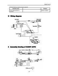
Other Factors to Consider<br />
Practical Center of Gravity as it Effects<br />
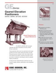
Gear Driven <strong>Positioner</strong>s<br />
• CG of a weldment is exactly in the center of asymmetrical<br />
weldment.<br />
• “A” is a symmetrical weldment: There is no top or bottom, just<br />
sides, the CG of a weldment is usually near the center of the<br />
weldment.<br />
• The ends and two sides of 1” steel plate. Each end is<br />
1x12x12 and weighs 40.8#. Each side is1x12x34, weighs<br />
115.6#. 115.6# x 2, plus 40.8# x 2 equals 312.8#. (Steel<br />
weighs approximately .283pounds/cubic inch.) If one end is<br />
secured to the table of a Gear Driven <strong>Positioner</strong>, the CG will<br />
be 18” out from or above the table. If either side, or the open<br />
top or bottom is secured to the table, the CG will be 6” above<br />
it.<br />
• “B” is also a symmetrical weldment: A 2” plate rib has been<br />
added in the middle, making the weldment a stiff column. The<br />
2x10x34 steel rib weighs 192.7# so the weldment now weighs<br />
505.5#. The rib being right in the middle added weight equally<br />
in opposite directions from center, so the CG is still in the<br />
dead center.<br />
• “C” is an un-symmetrical weldment: We want a box instead of<br />
a column, so we add a 2” thick bottom to weldment “A”.<br />
2x12x36 steel weighs 244.6# so total weight is now 557.6#.<br />
But the CG will not be at 7”, halfway from top or bottom,<br />
because we added nothing to the top to balance the weight of<br />
the bottom. We made no change at either end, and the bottom<br />
is as much left as right, so the CG remains 18” in from either<br />
end.<br />
• The CG always moves toward any part that is added to a<br />
symmetrical weldment. Locating the CG is a function of<br />
moments. “Moment” means force or tendency to produce<br />
motion. A Moment is weight multiplied by length (Arm). Like a<br />
lever. And like a lever, we must have a hinge point, a<br />
reference plane. The top surface of a Gear Driven <strong>Positioner</strong>’s<br />
table is our reference plane. Load Capacity Tables give<br />
ratings for various distances the CG is above the table, so this<br />
is very handy. Whenever possible, weldments should be<br />
mounted with the heavy side next to the table, so let’s figure it<br />
that way.<br />
• Each separate symmetrical part will have a known weight and<br />
CG, and the CG will be a known distance from the table top<br />
surface. Multiplying weight by distance (arm) gives the poundinch<br />
(lb-in) moment of the part. Adding all the moments and<br />
dividing by total weight gives the location of the CG of the<br />
weldment.<br />
We don’t need to take each end and each side<br />
separately because the side and ends make symmetrical<br />
mass weighing 312.8#, with the CG in the center of that<br />
mass. With the 2" plate between it and the table, the CG<br />
will be 8" above the table. 312.8# x 8" = 2502.41b-in.<br />
The 244.8# bottom’s CG is 1" above the table.<br />
244.8# x l" = 244 Ib-in.<br />
Adding 244.8 Ib-in and 2502.4 Ib-in equals 2747.2<br />
lb-in Total Moment. Dividing 2747.2 lb-in Total Moment<br />
by557.6 Total Weight locates the CG 4.9” above table top<br />
surface.<br />
Weldment ‘A’<br />
Weldment ‘B’<br />
Weldment ‘C’<br />
PAGE 6