Condensed Positioner USA - Koike
Condensed Positioner USA - Koike
Condensed Positioner USA - Koike

Create successful ePaper yourself
Turn your PDF publications into a flip-book with our unique Google optimized e-Paper software.
CUTTING, POSITIONING & WELDING EQUIPMENT<br />
KOIKE ARONSON RANSOME<br />
The Most Complete Line in the Industry
Table of Contents<br />
Sizing a <strong>Positioner</strong>.............4<br />
Universal Balance <strong>Positioner</strong>.............8<br />
Bench <strong>Positioner</strong>s...........12<br />
Gear Driven <strong>Positioner</strong>s<br />
10P..........14<br />
HD20 ..........16<br />
HD25 - 100 ..........18<br />
HD160 - 700 ..........20<br />
G400 - 2200 45/90..........22<br />
G3500 - 10,000 45/90..........24<br />
Elevating <strong>Positioner</strong>s<br />
GE 25-45..........26<br />
GE60 - 250..........28<br />
GE500 - 3500..........30<br />
P/E Elevating Models..........32<br />
Floor Turntables..........34<br />
Options..........36<br />
PAGE 3
How to Size a <strong>Positioner</strong><br />
HOW TO SELECT A GEAR DRIVEN POSITIONER TO BEST<br />
MEET YOUR NEEDS<br />
The illustration below shows a typical capacity plate that we<br />
attach to each Aronson Gear Driven <strong>Positioner</strong>. This happens to<br />
be the capacity plate for a Model HD400 Aronson Gear Driven<br />
unit. An HD400 is designed to handle loads up to 40,000 lbs<br />
(18,140kg) with a CG at a distance from the surface of the table<br />
of 12” (300mm). All the information required for loading the<br />
positioner is either on the capacity plate, or it can be simply<br />
calculated from the data on the plate<br />
Rotation Torque Load:<br />
To find your weldments’ Rotation Torque Load,<br />
multiply the weldment weight in Pounds by the distance<br />
in inches that Center-of-Gravity (CG) will be from the<br />
center of the table. This measurement is taken parallel to<br />
the table surface. Do not exceed the maximum load<br />
torque shown in the “rotation” column.<br />
12 In.<br />
300mm<br />
2,000 Lbs.<br />
907 Kg.<br />
KOIKE ARONSON<br />
Tilt Torque Load:<br />
To find your weldments’ Tilt Torque Load, add the<br />
Inherent Overhang (Inches) to the distance (Inches) the<br />
weldments’ CG is from the table top surface. This is measured<br />
perpendicular to the table top surface. Then multiply this total<br />
distance in Inches by the weight of the weldment. Do not exceed<br />
the maximum load torque shown in the “tilt” column on next page.<br />
How About Swing Clearance:<br />
When selecting a positioner, don’t forget to leave<br />
clearance to swing the work above the floor when the<br />
table is in the full tilt position. This is a common error in<br />
specifying positioners. For excessive work-pieces,<br />
Aronson positioners are available with manually<br />
adjustable bases, or powered Elevating bases which<br />
adjust the table height for larger work. Fixed-base<br />
machines also can be elevated by using a riser or subbase.<br />
PAGE 4
Load Capacity Tables<br />
Model<br />
Rotation<br />
Torque<br />
In/Lbs.<br />
Tilt Torque<br />
In/Lbs.<br />
INH<br />
O.H.<br />
inches<br />
CG<br />
@<br />
6”<br />
CG@<br />
12”<br />
CG@<br />
18”<br />
CG@<br />
24”<br />
CG@<br />
30”<br />
CG@<br />
36”<br />
CG@<br />
42”<br />
CG@<br />
48”<br />
CG@<br />
54”<br />
CG@<br />
60”<br />
CG@<br />
66”<br />
CG@<br />
72”<br />
10P — 6,000 10,500 4.5 1,000 635 466 365 — — — — — — — —<br />
HD20 — 12,000 21,000 4.5 2,000 930 730 600 520 450 400 360 325 — — —<br />
HD25 — 15,000 31,875 6.8 2,500 1,700 1,285 1,035 875 750 650 580 520 470 430 400<br />
HD30 — 36,000 56,250 6.8 — 3,000 2,270 1,830 1,530 1,300 1,100 1,000 900 830 760 700<br />
HD45 — 54,000 84,375 6.8 — 4,500 3,400 2,750 2,300 1,975 1,720 1,530 1,380 1,250 1,150 1,100<br />
HD60 — 72,000 123,000 8.5 — 6,000 4,650 3,790 3,200 2,750 2,400 2,200 1,900 1,700 1,600 1,500<br />
HD100 — 120,000 205,000 8.5 — 10,000 7,700 6,300 5,300 4,600 4,000 3,600 3,200 3,000 2,700 2,500<br />
HD160 — 192,000 336,000 9.0 — 16,000 12,400 10,000 8,600 7,400 6,600 5,900 5,300 4,800 4,400 4,000<br />
HD240 — 288,000 504,000 9.0 — 24,000 18,500 15,000 13,000 11,000 9,800 8,800 8,000 7,300 6,700 6,200<br />
HD400 G400 480,000 840,000 9.0 — 40,000 31,000 25,000 21,500 18,500 16,400 14,600 13,200 12,000 11,000 10,200<br />
HD500 G500 600,000 1,050,000 8.8 — 50,000 39,000 32,000 27,000 23,400 20,600 18,500 16,700 15,200 14,000 13,000<br />
HD600 G600 720,000 1,260,000 9.0 — 60,000 46,500 38,000 32,000 28,000 24,500 22,000 20,000 18,000 16,500 15,500<br />
HD700 G700 840,000 1,470,000 9.0 — 70,000 54,500 44,500 37,500 32,500 28,500 25,500 23,000 21,000 19,500 18,000<br />
G850 1,020,000 1,800,000 9.0 — 85,000 66,600 54,500 45,770 42,000 35,000 31,300 28,333 26,000 24,000 22,000<br />
G1200 1,440,000 2,880,000 12.0 — 120,000 96,000 80,000 68,600 60,000 53,400 48,000 43,600 40,000 37,000 34,200<br />
G2200 2,640,000 5,400,000 12.5 — 220,000 177,000 148,000 127,000 111,000 100,000 89,000 81,000 74,000 69,000 64,000<br />
G3500 4,200,000 9,300,000 14.5 — 350,000 286,000 240,000 208,430 184,000 164,160 148,400 135,000 125,000 115,000 107,000<br />
G7000 5,000,000 18,600,000 14.5 — 700,000 570,000 481,000 416,800 367,300 328,300 296,800 270,000 248,900 230,000 214,000<br />
G10000 12,000,000 30,000,000 18.0 — 1,000,000 833,000 714,000 625,000 555,500 500,000 454,500 416,500 384,500 357,000 333,000<br />
Model<br />
Rotation<br />
Torque<br />
In/Lbs.<br />
Tilt Torque<br />
In/Lbs.<br />
INH<br />
O.H.<br />
inches<br />
CG<br />
@<br />
6”<br />
CG@<br />
12”<br />
CG@<br />
18”<br />
CG@<br />
24”<br />
CG@<br />
30”<br />
CG@<br />
36”<br />
CG@<br />
42”<br />
CG@<br />
48”<br />
CG@<br />
54”<br />
CG@<br />
60”<br />
CG@<br />
66”<br />
CG@<br />
72”<br />
GE25 15,000 27,500 5.0 2,500 1,600 1,200 950 780 670 580 520 460 420 380 350<br />
GE30 36,000 60,750 8.2 — 3,000 2,300 1,880 1,600 1,375 1,200 1,075 975 890 820 750<br />
GE45 54,000 91,125 8.2 — 4,500 3,500 2,800 2,400 2,050 1,800 1,600 1,450 1,300 1,200 1,100<br />
GE60 72,000 123,000 8.5 — 6,000 4,650 3,790 3,200 2,750 2,400 2,200 1,900 1,700 1,600 1,500<br />
GE90 108,000 184,500 8.5 — 9,000 7,000 5,700 4,800 4,150 3,650 3,250 2,950 2,700 2,480 2,300<br />
GE120 144,000 252,000 9.0 — 12,000 9,300 7,600 6,450 5,600 4,950 4,400 4,000 3,650 3,350 3,100<br />
GE180 216,000 369,000 8.5 — 18,000 13,900 11,350 9,600 8,300 7,300 6,500 5,900 5,400 4,950 4,600<br />
GE250 300,000 512,500 8.5 — 25,000 19,400 15,800 13,300 11,500 10,200 9,000 8,200 7,500 6,900 6,400<br />
GE500 600,000 1,050,000 8.8 — 50,000 39,000 32,000 27,000 23,400 20,600 18,500 16,700 15,200 14,000 13,000<br />
GE850 1,020,000 1,800,000 9.0 — 85,000 66,111 54,091 45,770 39,667 35,000 31,316 28,333 25,870 23,800 22,000<br />
GE1200 1,440,000 2,880,000 12.0 — 120,000 96,000 80,000 68,600 60,000 53,400 48,000 43,600 40,000 37,000 34,200<br />
GE3500 2,640,000 9,300,000 14.5 — 350,000 285,000 240,000 208,500 183,500 164,000 148,000 135,000 124,000 115,000 107,000<br />
Models and specifications subject to change without notice.<br />
For models greater than 350,000 Lbs. capacity, please consult Factory<br />
PAGE 5
Other Factors to Consider<br />
Practical Center of Gravity as it Effects<br />
Gear Driven <strong>Positioner</strong>s<br />
• CG of a weldment is exactly in the center of asymmetrical<br />
weldment.<br />
• “A” is a symmetrical weldment: There is no top or bottom, just<br />
sides, the CG of a weldment is usually near the center of the<br />
weldment.<br />
• The ends and two sides of 1” steel plate. Each end is<br />
1x12x12 and weighs 40.8#. Each side is1x12x34, weighs<br />
115.6#. 115.6# x 2, plus 40.8# x 2 equals 312.8#. (Steel<br />
weighs approximately .283pounds/cubic inch.) If one end is<br />
secured to the table of a Gear Driven <strong>Positioner</strong>, the CG will<br />
be 18” out from or above the table. If either side, or the open<br />
top or bottom is secured to the table, the CG will be 6” above<br />
it.<br />
• “B” is also a symmetrical weldment: A 2” plate rib has been<br />
added in the middle, making the weldment a stiff column. The<br />
2x10x34 steel rib weighs 192.7# so the weldment now weighs<br />
505.5#. The rib being right in the middle added weight equally<br />
in opposite directions from center, so the CG is still in the<br />
dead center.<br />
• “C” is an un-symmetrical weldment: We want a box instead of<br />
a column, so we add a 2” thick bottom to weldment “A”.<br />
2x12x36 steel weighs 244.6# so total weight is now 557.6#.<br />
But the CG will not be at 7”, halfway from top or bottom,<br />
because we added nothing to the top to balance the weight of<br />
the bottom. We made no change at either end, and the bottom<br />
is as much left as right, so the CG remains 18” in from either<br />
end.<br />
• The CG always moves toward any part that is added to a<br />
symmetrical weldment. Locating the CG is a function of<br />
moments. “Moment” means force or tendency to produce<br />
motion. A Moment is weight multiplied by length (Arm). Like a<br />
lever. And like a lever, we must have a hinge point, a<br />
reference plane. The top surface of a Gear Driven <strong>Positioner</strong>’s<br />
table is our reference plane. Load Capacity Tables give<br />
ratings for various distances the CG is above the table, so this<br />
is very handy. Whenever possible, weldments should be<br />
mounted with the heavy side next to the table, so let’s figure it<br />
that way.<br />
• Each separate symmetrical part will have a known weight and<br />
CG, and the CG will be a known distance from the table top<br />
surface. Multiplying weight by distance (arm) gives the poundinch<br />
(lb-in) moment of the part. Adding all the moments and<br />
dividing by total weight gives the location of the CG of the<br />
weldment.<br />
We don’t need to take each end and each side<br />
separately because the side and ends make symmetrical<br />
mass weighing 312.8#, with the CG in the center of that<br />
mass. With the 2" plate between it and the table, the CG<br />
will be 8" above the table. 312.8# x 8" = 2502.41b-in.<br />
The 244.8# bottom’s CG is 1" above the table.<br />
244.8# x l" = 244 Ib-in.<br />
Adding 244.8 Ib-in and 2502.4 Ib-in equals 2747.2<br />
lb-in Total Moment. Dividing 2747.2 lb-in Total Moment<br />
by557.6 Total Weight locates the CG 4.9” above table top<br />
surface.<br />
Weldment ‘A’<br />
Weldment ‘B’<br />
Weldment ‘C’<br />
PAGE 6
Notes<br />
PAGE 7
UBSeries<br />
Universal Balance <strong>Positioner</strong><br />
Features<br />
Machined Tables<br />
Caster Bases Available<br />
Manual Height Adjustment<br />
Friction Lock Brakes<br />
Powered rotation<br />
available<br />
<strong>Koike</strong> Aronson Ransome Universal Balance <strong>Positioner</strong>s allow safe and<br />
quick manipulation of large, awkward work objects when it is critical to maintain<br />
an efficient down-hand welding position. A welder can position objects up to<br />
4,000 Lbs. By simply applying fingertip pressure and does not need to raise a<br />
helmet or break an arc.<br />
The Universal Balance principle is to intersect the rotational axis center<br />
of gravity with that of the tilt axis. Work pieces can then be rotated 360 degrees<br />
around both axis, and in most cases around the <strong>Positioner</strong> column. A<br />
universally balanced load allows effortless access to any desired location upon a<br />
mounted fixture.<br />
Versatile Performance, Infinite Applications<br />
Capacities from 25 to 4,000 Lbs.<br />
KOIKE ARONSON, INC. / RANSOME<br />
PAGE 8
UBSeries<br />
Set-Up<br />
1. Find Center of Gravity<br />
for rotation.<br />
Workpiece should be placed on<br />
positioner with the center of gravity<br />
coinciding with the rotational axis of<br />
the table. Movement of the object<br />
around table rotational axis is<br />
almost effortless. In order to prevent<br />
over-travel of mounted objects,<br />
<strong>Koike</strong> Aronson has applied friction<br />
bands to the rotation point of the<br />
worktable which generates slight<br />
resistance and allows the load to be<br />
stopped at any desired point.<br />
<strong>Koike</strong> Aronson<br />
universal balance<br />
positioners allow<br />
welders to maintain<br />
the most productive<br />
10˚ downhand<br />
welding position.<br />
10˚<br />
Vertical Up—<br />
4-1/4" per min<br />
Flat—<br />
12" per min<br />
Downhand at 10˚—<br />
19"per min<br />
Workpiece<br />
Center of Gravity<br />
Rotates Easily<br />
2. Finally, balance workpiece by<br />
adjusting wormgear so tilt axis<br />
intersects center of gravity of<br />
rotational axis.<br />
0-30°<br />
By a simple adjustment to the<br />
wormgear, the tilt axis can be<br />
aligned to intersect the rotational<br />
axis. At this point, both axes<br />
intersect the object’s center of<br />
gravity and move freely in any<br />
direction.<br />
Center of Gravity<br />
of Workpiece<br />
Rotational Axis<br />
Tilt<br />
Axis<br />
A wrench adjustment to the worm<br />
on the wormgear sector will change<br />
the angle of the arm.<br />
<strong>Koike</strong> Aronson Inc.<br />
P.O. Box 307, Arcade, New York 14009<br />
Phone (585) 492-2400 Fax (585) 457-3517<br />
www.koike.com<br />
PAGE 9
Specifications<br />
Universal Balance <strong>Positioner</strong><br />
SPECIFICATIONS C25 C100 C1000 C2000 C4000<br />
Maximum Load 25 Lbs. 100 Lbs. 1,000 Lbs. 2,000 Lbs. 4,000 Lbs.<br />
DIM A, Overhang, 6-1/2” 11” 32” 35” 51-1/2”<br />
DIM B, Max. CG Height 3” 4-3/4” 14-1/2” 16” 33-1/2”<br />
DIM C, Max. Part Diameter 14” 20” 66” 75” 96”<br />
DIM D, Max. Part Length 16” 24” 100” 100” 96”<br />
DIM E, Table Diameter 1-1/2” 5” 8” 8” 12”<br />
DIM F, Hole Size 10-32 1/4” Slots 17/32” 17/32” 1-1/32”<br />
DIM G, Bolt Circle 1-1/4” 4 Slots 5” 5” 8”<br />
DIM H, Table Thickness 1/4” 1/4” 15/16” 1” 1-1/2”<br />
DIM I, Pilot Hole 10-32 1/4-20 1/2-13 3/4-10 1”-8 x 1.25<br />
DIM J, Height Range 6-1/4” Fix 5” Fix 27”- 37” 30”- 36” 41-1/2” Fix<br />
DIM K, Table to Tilt Axis 7/8” 2” 3-5/8” 3-1/8” 6”<br />
DIM L, Rear Overhang 1-1/2” 2-1/8” 4-3/4” 8” 1”<br />
DIM M, Base Overall Width 6” 4-1/2” 43” 43” 58”<br />
DIM N, Base Overall Length. 9” 4-1/2” 37-3/4” 48” 78”<br />
DIM O, Anchor Hole Size 9/32” (4) 13/32” (4) 9/16” (4) 9/16” (6) 13/16” (8)<br />
DIM P, Anchor Hole Width Centers 5-1/4” 3-3/4” 40” 40” 55”<br />
DIM Q, Anchor Hole Length Centers 8-1/4” 3-3/4” 29-3/4” 39” -<br />
DIM R, Wrench Size 1/4” 1/2” 1” 1” 2-1/4”<br />
Type of Base Plate Plate “T” “T” “T”<br />
Tilt Axis Brake Yes No Yes Yes Yes<br />
Tilt Axis Pinlock No No Yes Yes Yes<br />
Rotation Axis Brake Yes No Yes Yes Yes<br />
Rotation Axis Pinlock No Yes Yes Yes Yes<br />
Bearing type Ball Tapered Tapered Tapered Tapered<br />
Ground Current Conduction N/R 300 Amps 800 Amps 1200 Amps 2000 Amps<br />
Power Axis Available No No Yes Yes Yes<br />
Shipping Weight 15 Lbs. 30 Lbs. 340 Lbs. 500 Lbs. 1,300 Lbs.<br />
***All dimensions are for reference only and subject to change without notice.<br />
<strong>Koike</strong> Aronson Inc.<br />
P.O. Box 307, Arcade, New York 14009<br />
Phone (585) 492-2400 Fax (585) 457-3517<br />
www.koike.com<br />
PAGE 10
UBSeries<br />
C2000<br />
C2000 P30<br />
C100<br />
C1000 Caster<br />
C4000<br />
ASSEMBLY POSITIONER<br />
Assembly positioners brake and hold workpieces in any<br />
position with the use of hydraulic disc brakes. Rotation<br />
and tilt are performed manually, off-balance loads can be<br />
quickly manipulated and locked in place to resist the<br />
forces of various production operations.<br />
<strong>Koike</strong> Aronson Inc.<br />
P.O. Box 307, Arcade, New York 14009<br />
Phone (585) 492-2400 Fax (585) 457-3517<br />
www.koike.com<br />
PAGE 11
BENCHSeries<br />
BENCH MODEL POSITIONERS<br />
Models—B1 and B3<br />
Features<br />
Variable speed SCR solid<br />
state electronic drives<br />
Machined Tables<br />
Standard foot switch<br />
control<br />
Unitized rotation motor<br />
and drive<br />
135° forward tilt<br />
Welding chucks available<br />
<strong>Koike</strong> Aronson/Ransome Bench Model <strong>Positioner</strong>s are<br />
Engineered to provide versatility and safety over a range of 100 to<br />
300 pounds. 135° Forward tilt is achieved by manual hand-wheel<br />
operation. Variable speed Drives and Motors are provided to<br />
maintain precise speed and control during the welding process.<br />
Start/Stop foot switch is standard.<br />
Capacities from 100 to 300 pounds<br />
KOIKE ARONSON, INC. / RANSOME<br />
PAGE 12
Specifications<br />
Bench <strong>Positioner</strong>s<br />
SPECIFICATIONS B1 B3<br />
MAXIMUM LOAD<br />
100 Lbs. @ 1” Off Table & Concentric on<br />
table<br />
ROTATION 0.1 TO 4 RPM Variable Speed @ 100<br />
IN.LB. Torque<br />
300 Lbs. @ 3” Off Table & 3” Eccentric<br />
0.06 TO 2.5 RPM Variable Speed @ 900<br />
IN.LB. Torque<br />
TILT 125° Forward Tilt-Powered by a Handwheel 125° Forward Tilt-Powered by a Handwheel<br />
ELECTRICALS<br />
SCR DC Drive with Ready Light Toggle<br />
Disconnect Switch 1-Turn Speed<br />
Pententiometer CW-CCW Selector Switch<br />
Remote ON/OFF Foot Switch, Primary<br />
Cable and Plug<br />
WELD GROUND CURRENT 190 Amps 500 Amps<br />
VOLTAGE<br />
115V/1PH/50-60HZ, Remote ON/OFF Foot<br />
Switch<br />
SHIPPING WEIGHT 90 Lbs. 202 Lbs.<br />
***All dimensions are for reference only and subject to change without notice.<br />
SCR DC Drive with Ready Light Toggle<br />
Disconnect Switch 1-Turn Speed<br />
Pententiometer CW-CCW Selector Switch<br />
Remote ON/OFF Foot Switch, Primary<br />
Cable and Plug<br />
115V/1PH/50-60HZ, Remote ON/OFF Foot<br />
Switch<br />
B3 <strong>Positioner</strong><br />
B1 <strong>Positioner</strong><br />
<strong>Koike</strong> Aronson Inc.<br />
P.O. Box 307, Arcade, New York 14009<br />
Phone (585) 492-2400 Fax (585) 457-3517<br />
www.koike.com<br />
PAGE 13
PSeries<br />
10P GEAR DRIVEN POSITIONER<br />
Features<br />
Variable speed SCR solid<br />
state electronic drives<br />
Machined table<br />
Unitized tilt motor and<br />
drive<br />
135° forward tilt<br />
Welding chucks available<br />
The <strong>Koike</strong> Aronson/Ransome 10P <strong>Positioner</strong> is engineered to<br />
provide versatility and safety. Variable speed drives and motors are<br />
provided to maintain precise rotation speed and control during the<br />
welding process. 135°Forward tilt is powered by a constant speed<br />
motor. Hand pendant control includes Start/Stop/Forward/Reverse, 10<br />
turn speed potentiometer and Rapid Traverse. Adjustable base<br />
provides 5 separate height settings for various size work pieces. Table<br />
slots are provided for easy fixturing and mounting of weldments. Tilt<br />
protractor enables operator to repeat welding positions quickly and<br />
precisely.<br />
Manually Adjustable From 32-1/2” to 50-1/2”<br />
KOIKE ARONSON, INC. / RANSOME<br />
PAGE 14
Specifications<br />
10P GEAR DRIVEN POSTIONER<br />
SPECIFICATIONS<br />
CAPACITY<br />
ROTATION<br />
TILT<br />
TABLE<br />
FLAT TABLE HEIGHT<br />
WELD GROUND CURRENT<br />
10P<br />
1,000 LBS. Load Capacity, Center of Gravity 6" Overhang, 6" Off-center<br />
.04 - 2 RPM @ 6,000 Lb-In Torque, 1/2 HP AC Motor, Variable Frequency Drive<br />
135° Forward Tilt, 10,500 Lb-In Torque, .4 RPM (90° in 38 Seconds) 1/2 HP Brake Motor; 4.5” Inherent Overhang<br />
30" Diameter Machined Table Top, with (4) Radial 'T' slots for 1/2" Diameter Bolts, 2.500 x ½” deep Pilot, 1-¾” Thru<br />
Minimum 32-1/2" from Floor, Maximum 50-1/2", Manually Adjustable in 6" Increments<br />
1000 Amps<br />
VOLTAGE 460/3/60<br />
SHIPPING WEIGHT<br />
1,180 Lbs.<br />
***All dimensions are for reference only and subject to change without notice.<br />
<strong>Koike</strong> Aronson Inc.<br />
P.O. Box 307, Arcade, New York 14009<br />
Phone (585) 492-2400 Fax (585) 457-3517<br />
www.koike.com<br />
PAGE 15
HDSeries<br />
HD20 GEAR DRIVEN POSITIONER<br />
Features<br />
Boxed section design that<br />
is stronger and will not<br />
distort support gearing<br />
when loaded<br />
Motors are mounted for<br />
easy access and sealed<br />
from dust contamination<br />
Limit switches and<br />
precision adjustable tiltstop<br />
triggers for accurate<br />
tilt setup and over-travel<br />
prevention<br />
Ground blocks for positive<br />
clamping of cable terminals<br />
to assure continuous, nonvarying<br />
weld current<br />
The HD20 Gear Driven <strong>Positioner</strong> is designed to be a cost<br />
effective solution for positioning 2,000 Lbs. or less. 12,000 In-Lbs.<br />
rotation gearing provides safety and stability. Variable speed and<br />
standard 115V wall voltage make this a very versatile machine. A<br />
standard T-slot table design allows almost any fixture or part to be<br />
easily adapted to the <strong>Positioner</strong>. 20’ power cord included with<br />
machine.<br />
115/1/60—2,000 Lbs. Machine<br />
Cost-Effective Solution for<br />
Precision Positioning<br />
KOIKE ARONSON, INC. / RANSOME<br />
Heavy duty precision final<br />
drive gearing for smooth<br />
table rotation with a<br />
minimum of lost motion<br />
High load capacity tapered<br />
roller bearings are<br />
preloaded on spindles for<br />
guaranteed weld ground<br />
conduction<br />
Tables have full length slots<br />
with nut access in bottom<br />
side or edge<br />
PAGE 16
Specifications<br />
HD20 GEAR DRIVEN POSTIONER<br />
Tilt: Load Torque, In-Lbs.<br />
Rating Lbs. @ 4” CG Height<br />
Rating Lbs. @6” CG Height<br />
Rating Lbs. @12” CG Height<br />
Rating Lbs. @18” CG Height<br />
Rating Lbs. @24” CG Height<br />
Rating Lbs. @30” CG Height<br />
Rating Lbs. @36” CG Height<br />
Rating Lbs. @42” CG Height<br />
Rating Lbs. @48” CG Height<br />
Rating Lbs. @54” CG Height<br />
Rating Lbs. @60” CG Height<br />
Rotation: Load Torque, In/Lbs.<br />
Rating Lbs. @ 4” Eccentricity<br />
Rating Lbs.@ 6” Eccentricity<br />
Rating Lbs. @12” Eccentricity<br />
Tilt: 135º in Seconds<br />
Motor HP<br />
Rotation: Speed Range<br />
Motor HP<br />
HD20<br />
21,000<br />
2,000<br />
2,000<br />
1,275<br />
930<br />
730<br />
600<br />
520<br />
450<br />
400<br />
360<br />
325<br />
12,000<br />
2,000<br />
2,000<br />
1,000<br />
22 Sec.<br />
1/2 Hp<br />
2.0—.04 RPM<br />
1/2 Hp<br />
Pendant Cable Length 20’<br />
A: Table Diameter<br />
24”<br />
B: Max. Clamping Dia.<br />
22-1/2”<br />
C: No. of slots and width<br />
(4) 9/16”<br />
D: Table Thickness<br />
1/2”<br />
Pilot hole and Depth<br />
1-1/2” x 1/2”<br />
E: Inherent Overhang<br />
4-1/2”<br />
Weld Current Conduction:<br />
Spindle OD:<br />
Hollow Spindle ID<br />
1,000 Amps<br />
2”<br />
1-3/8”<br />
F: Table flat dim. from floor 23-3/4”- 31-3/4” - 38-3/4”<br />
G: Rotation axis dim. from floor 19-1/4” - 27-1/4” - 34-1/4”<br />
H: Base mounting holes<br />
(4) 9/16”<br />
I: Front mounting hole location<br />
1-1/2”<br />
J: front to rear mounting holes<br />
32-1/2”<br />
K: Traverse center distance<br />
26-5/8”<br />
L: Base length overall<br />
35-1/2”<br />
M: Model width overall<br />
40”<br />
N: Model length overall<br />
48”<br />
Primary Voltage: 115/1/60<br />
Shipping Weight:<br />
755 Lbs.<br />
***All dimensions are for reference only and<br />
subject to change without notice.<br />
<strong>Koike</strong> Aronson Inc.<br />
P.O. Box 307, Arcade, New York 14009<br />
Phone (585) 492-2400 Fax (585) 457-3517<br />
www.koike.com<br />
PAGE 17
HDSeries<br />
HD25 Thru HD100<br />
Features<br />
135º powered forward tilt<br />
NEMA 12 Electricals<br />
Pin-through post manual<br />
height adjustment<br />
90,000 psi aluminum-bronze<br />
low efficiency wormgear<br />
drive reduces back driving<br />
All steel welded gearboxes<br />
Low voltage hand control<br />
pendants<br />
50:1 Variable speed drives<br />
The HD25 - HD100 series <strong>Positioner</strong>s provide a mid-range<br />
lineup that can run around the clock. These machines are<br />
engineered to provide rugged performance, yet they can easily be<br />
transported through your facility.<br />
Models larger than the HD25 utilize double tilt gears which<br />
stabilize loads and prevent chassis warpage. The entire series<br />
features up-right motors safely mounted within the chassis and<br />
straddle supported tilt pinions to prevent misalignment of the<br />
rotational drive gearing. This group of gear driven <strong>Positioner</strong>s are<br />
designed by <strong>Koike</strong> Aronson Inc. Ransome to offer the most in both<br />
performance and safety.<br />
AC brake motors<br />
Standard hand pendant provided with all models<br />
Capacities from 2,500 to 10,000 pounds<br />
Optional foot switch controls available<br />
KOIKE ARONSON, INC. / RANSOME<br />
PAGE 18
Specifications<br />
HD25VF - HD100VF<br />
SPECIFICATIONS HD25VF HD30VF HD45VF HD60VF HD100VF<br />
Tilt: Load Torque in-lb (N.m)<br />
Rating Lbs.(kg) @ 6” (152mm) CG Height<br />
Rating Lbs.(kg) @ 12” (305mm) CG Height<br />
Rating Lbs.(kg) @ 18” (457mm) CG Height<br />
Rating Lbs.(kg) @ 24” (609mm) CG Height<br />
Rating Lbs.(kg) @ 30” (762mm) CG Height<br />
Rating Lbs.(kg) @ 36” (914mm) CG Height<br />
Rating Lbs.(kg) @ 42” (1067mm) CG Height<br />
Rating Lbs.(kg) @ 48” (1219mm) CG Height<br />
Rating Lbs.(kg) @ 54” (1371mm) CG Height<br />
Rating Lbs.(kg) @ 60” (1524mm) CG Height<br />
Rating Lbs.(kg) @ 66” (1676mm) CG Height<br />
Rating Lbs.(kg) @ 72” (1829mm) CG Height<br />
31,875 (3602)<br />
2,500 (1134)<br />
1,700 (771)<br />
1,285 (583)<br />
1,035 (469)<br />
875 (397)<br />
750 (340)<br />
650 (295)<br />
580 (263)<br />
520 (236)<br />
470 (213)<br />
430 (195)<br />
400 (181)<br />
56,250 (6356)<br />
3,000 (1361)<br />
3,000 (1361)<br />
2,270 (1030)<br />
1,830 (830)<br />
1,530 (694)<br />
1,300 (590)<br />
1,100 (499)<br />
1,000 (453)<br />
900 (408)<br />
830 (376)<br />
760 (345)<br />
700 (317)<br />
84,375 (9534)<br />
4,500 (2041)<br />
4,500 (2041)<br />
3,400 (1542)<br />
2,750 (1247)<br />
2,300 (1043)<br />
1,975 (896)<br />
1,720 (780)<br />
1,530 (694)<br />
1,380 (626)<br />
1,250 (567)<br />
1,150 (522)<br />
1,100 (499)<br />
123,000 (13899)<br />
-<br />
6,000 (2721)<br />
4,650 (2109)<br />
3,790 (1719)<br />
3,200 (1451)<br />
2,750 (1247)<br />
2,400 (1089)<br />
2,200 (998)<br />
1,900 (862)<br />
1,700 (771)<br />
1,600 (726)<br />
1,500 (680)<br />
205,000 (23165)<br />
-<br />
10,000 (4536)<br />
7,700 (3493)<br />
6,300 (2858)<br />
5,300 (2404)<br />
4,600 (2086)<br />
4,000 (1814)<br />
3,600 (1633)<br />
3,200 (1451)<br />
3,000 (1361)<br />
2,700 (1225)<br />
2,500 (1134)<br />
Rotation: Load Torque in-lb (N.m)<br />
Rating Lbs.(kg) @ 6” (152mm) Eccentric<br />
Rating Lbs.(kg) @ 12” (305mm) Eccentric<br />
15,000 (1695)<br />
2,500 (1134)<br />
1,250 (567)<br />
36,000 (4068)<br />
3,000 (1361)<br />
3,000 (1350)<br />
54,000 (6102)<br />
4,500 (2041)<br />
4,500 (2041)<br />
72,000 (8136)<br />
-<br />
6,000 (2721)<br />
120,000 (13560)<br />
-<br />
10,000 (4536)<br />
Tilt: 135º in how many seconds<br />
Tilt Motor Horse Power<br />
23 Sec.<br />
1 HP<br />
20 Sec.<br />
2 HP<br />
20 Sec.<br />
3 HP<br />
24 Sec.<br />
3 HP<br />
49 Sec.<br />
3 HP<br />
Rotation: Speed Range 50:1 AC Drive<br />
Rotation Motor Horse Power<br />
2.0 - .040 rpm<br />
¾ HP<br />
1.2 - .024 rpm<br />
1 HP<br />
1.2 - .024 rpm<br />
1-½ HP<br />
1.5 - .030 rpm<br />
3 HP<br />
1.0—.020<br />
5 HP<br />
Pendant cable length: 20 ft. 20 ft. 20 ft. 20 ft. 20 ft.<br />
A: Table Size<br />
B: Maximum Clamping Diameter<br />
C: Number of slots and width<br />
Number of Table nuts and Thread<br />
D: Pilot hole and depth<br />
E: Table Thickness<br />
F: Inherent Overhang<br />
30” x 30” (762x762mm)<br />
38-½ ” (978mm)<br />
(4) 13/16” (20.6mm)<br />
(4) ¾-10 ”<br />
3.130”x½” (79.5 x13mm)<br />
1-¾ “ (44.4mm)<br />
6-¾ “ (171.4mm)<br />
36” x 36” (914x914mm)<br />
47 ” (1194mm)<br />
(4) 13/16” (20.6mm)<br />
(4) ¾-10 ”<br />
3.130”x½” (79.5 x13mm)<br />
1-¾ “ (44.4mm)<br />
6-¾ “ (171.4mm)<br />
36” x 36” (914x914mm)<br />
47 ” (1194mm)<br />
(4) 13/16” (20.6mm)<br />
(4) ¾-10 ”<br />
3.130”x½” (79.5 x13mm)<br />
1-¾ “ (44.4mm)<br />
6-¾ “ (171.4mm)<br />
48” x 48” (1219 x 1219mm)<br />
65” (1651mm)<br />
(4) 13/16” (20.6mm)<br />
(4) 3/4”-10<br />
3.130” x ½” (79.5 x 12.7mm)<br />
2” (50.8mm)<br />
8 1/2” (215.9mm)<br />
48” x 48” (1219 x 1219mm)<br />
65” (1651mm)<br />
4) 13/16” (20.6mm)<br />
(4) 3/4”-10<br />
3.130” x ½” (79.5 x 12.7mm)<br />
2” (50.8mm)<br />
8 1/2” (215.9mm)<br />
Spindle OD Bearing Bore<br />
Hollow Spindle Dia<br />
2-1/2” (63.5mm)<br />
None<br />
2-1/2” (63.5mm)<br />
None<br />
3” (76.2mm)<br />
None<br />
3” (76.2mm)<br />
None<br />
4” (101.6mm)<br />
None<br />
Weld Current Conduction 1,500 Amps 1,500 Amps 2,000 Amps 2,000 Amps 2,000 Amps<br />
G: Table flat, Minimum Height<br />
Table flat, Maximum Height<br />
Adjustment Increments<br />
34-½” (870mm)<br />
56-½” (1435mm)<br />
5-½” (139.7mm)<br />
34-½” (870mm)<br />
54-½” (1384.3mm)<br />
5” (127mm)<br />
34-½” (870mm)<br />
54-½” (1384.3mm)<br />
5” (127mm)<br />
44-½” (1130.3mm)<br />
68-½” (1740mm)<br />
6” (152.4mm)<br />
44-½” (1130.3mm)<br />
74-½” (1892.3mm)<br />
6” (152.4mm)<br />
H: Rotation axis, Minimum Height<br />
Rotation axis, Maximum Height<br />
Matching TS<br />
27-¾” (704.8mm)<br />
49-¾” (1263.6mm)<br />
TS2<br />
27-¾” (704.8mm)<br />
47-¾” (1212.8mm)<br />
TS2<br />
27-¾” (704.8mm)<br />
47-¾” (1212.8mm)<br />
TS4<br />
36” (914.4mm)<br />
60” (1524mm)<br />
TS6<br />
36” (914.4mm)<br />
66” (1676mm)<br />
TS10<br />
I: Tie down hole size<br />
J: Front Mounting hole location<br />
K: Center mounting hole location<br />
L: Rear mounting hole location<br />
M: Bolt hole pattern pitch<br />
N: Overall base length<br />
O: Overall Machine width<br />
P: Overall machine length<br />
(6) 9/16” (14.3mm)<br />
1-½” (38.1mm)<br />
19” (482.6mm)<br />
19” (482.6mm)<br />
34” (863.6mm)<br />
42-¼” (1073.1mm)<br />
47” (1194mm)<br />
50-¾” (1289mm)<br />
(6) 13/16” (20.6mm)<br />
1-½” (38.1mm)<br />
23” (584.2mm)<br />
20” (508mm)<br />
35-¾” (908mm)<br />
48” (1219.2mm)<br />
48-¾” (1225mm)<br />
60” (1524mm)<br />
(6) 13/16” (20.6mm)<br />
1-½” (38.1mm)<br />
23” (584.2mm)<br />
20” (508mm)<br />
35-¾” (908mm)<br />
48” (1219.2mm)<br />
48-3/8” (1229mm)<br />
60” (1524mm)<br />
(6) 13/16” (20.6mm)<br />
2” (50.8mm)<br />
30” (762mm)<br />
24” (609.6mm)<br />
47-1/2” (1206.5mm)<br />
60” (1524mm)<br />
63-3/8” (1610mm)<br />
76” (1930.4mm)<br />
(6) 13/16” (20.6mm)<br />
2” (50.8mm)<br />
30” (762mm)<br />
24” (609.6mm)<br />
47-5/8” (1209.7mm)<br />
60” (1524mm)<br />
61-13/16” (1570mm)<br />
76” (1930.4mm)<br />
Standard Primary Voltage 460/3/60 460/3/60 460/3/60 460/3/60 460/3/60<br />
Shipping Weight 1500 lbs. (680kg) 1892 lbs. (858kg) 2080 lbs. (943kg) 3700 lbs. (1678kg) 4105 lbs. (1862kg)<br />
***All dimensions<br />
are for reference only<br />
and subject to change<br />
without notice.<br />
<strong>Koike</strong> Aronson Inc.<br />
P.O. Box 307, Arcade, New York 14009<br />
Phone (585) 492-2400 Fax (585) 457-3517<br />
www.koike.com<br />
PAGE 19
HDSeries<br />
HD160 thru HD700<br />
Features<br />
135º powered forward tilt<br />
NEMA 12 Electricals<br />
Pin-through post manual<br />
height adjustment<br />
90,000 psi aluminum-bronze<br />
low efficiency wormgear<br />
drive reduces back driving<br />
All steel welded gearboxes<br />
Low voltage hand control<br />
pendants<br />
50:1 Variable speed drives<br />
AC brake motors<br />
The HD160 - HD700 series positioners are built to perform with<br />
larger capacities with their strong boxed chassis and high precision<br />
gearing.<br />
<strong>Positioner</strong>s larger than the HD240 are equipped with massive box<br />
beam trunnions, spur gear final drive for table rotation, and aluminumbronze<br />
wormgear drive of the spur tilt pinions.<br />
The only thing that contradicts the large capacity of this series is<br />
their portability. They can be easily moved anywhere to tackle the<br />
largest of jobs.<br />
Standard hand pendant provided with all models<br />
Capacities from 16,000 to 70,000 pounds<br />
Optional foot switch controls available<br />
KOIKE ARONSON, INC. / RANSOME<br />
PAGE 20
Specifications<br />
HD160VF - HD700VF<br />
SPECIFICATIONS HD160VF HD240VF HD400VF HD500VF HD600VF<br />
HD700VF<br />
Tilt: Load Torque in-lb (N.m)<br />
Rating Lbs.(kg) @ 6” (152mm) CG Height<br />
Rating Lbs.(kg) @ 12” (305mm) CG Height<br />
Rating Lbs.(kg) @ 18” (457mm) CG Height<br />
Rating Lbs.(kg) @ 24” (609mm) CG Height<br />
Rating Lbs.(kg) @ 30” (762mm) CG Height<br />
Rating Lbs.(kg) @ 36” (914mm) CG Height<br />
Rating Lbs.(kg) @ 42” (1067mm) CG Height<br />
Rating Lbs.(kg) @ 48” (1219mm) CG Height<br />
Rating Lbs.(kg) @ 54” (1371mm) CG Height<br />
Rating Lbs.(kg) @ 60” (1524mm) CG Height<br />
Rating Lbs.(kg) @ 66” (1676mm) CG Height<br />
Rating Lbs.(kg) @ 72” (1829mm) CG Height<br />
336,000 (37968)<br />
-<br />
16,000(7257)<br />
12,400 (5624)<br />
10,000 (4536)<br />
8,600 (3901)<br />
7,400 (3356)<br />
6,600 (2994)<br />
5,900 (2676)<br />
5,300 (2404)<br />
4,800 (2177)<br />
4,400 (1996)<br />
4,000 (1814)<br />
504,000 (56952)<br />
-<br />
24,000 (10886)<br />
18,500 (8391)<br />
15,000 (6804)<br />
13,000 (5897)<br />
11,000 (4989)<br />
9,800 (4445)<br />
8,800 (3992)<br />
8,000 (3629)<br />
7,300 (3311)<br />
6,700 (3039)<br />
6200 (2812)<br />
830,000 (93790)<br />
-<br />
40,000 (18144)<br />
31,000 (14061)<br />
25,000 (11340)<br />
21,500 (9752)<br />
18,500 (8391)<br />
16,400 (7439)<br />
14,600 (6622)<br />
13,200 (5987)<br />
12,000 (5443)<br />
11,000 (4989)<br />
10,200 (4627)<br />
1,037,500 (117238)<br />
-<br />
50,000 (22680)<br />
39,000 (17690)<br />
32,000 (14515)<br />
27,500 (12473)<br />
23,450 (10636)<br />
20,600 (9344)<br />
18,500 (8391)<br />
16,700 (7575)<br />
15,200 (6895)<br />
14,000 (6350)<br />
13,000 (5897)<br />
1,260,000 (142380)<br />
-<br />
60,000 (27215)<br />
46,500 (21092)<br />
38,000 (17236)<br />
32,000 (14515)<br />
28,000 (12700)<br />
24,500 (11113)<br />
22,000 (9979)<br />
20,000 (9072)<br />
18,000 (8165)<br />
16,500 (7484)<br />
15,500 (6975)<br />
1,470,000 (166110)<br />
-<br />
70,000 (31751)<br />
54,500 (24721)<br />
44,500 (20185)<br />
37,500 (17010)<br />
32,500 (14742)<br />
28,500 (12927)<br />
25,500 (11567)<br />
23,000 (10433)<br />
21,000 (9525)<br />
19,500 (8845)<br />
18,000 (8165)<br />
Rotation: Load Torque in-lb (N.m)<br />
Rating Lbs.(kg) @ 6” (152mm) Eccentric<br />
Rating Lbs.(kg) @ 12” (305mm) Eccentric<br />
192,000 (21696)<br />
-<br />
16,000 (7257)<br />
288,000 (32544)<br />
-<br />
24,000 (10886)<br />
480,000 (54240)<br />
-<br />
40,000 (18144)<br />
600,000 (67800)<br />
-<br />
50,000 (22680)<br />
720,000 (81360)<br />
-<br />
60,000 (27215)<br />
840,000 (94920)<br />
-<br />
70,000 (31751)<br />
Tilt: 135º in how many seconds<br />
Tilt Motor Horse Power<br />
46 Sec.<br />
5 HP<br />
46 Sec.<br />
7-½ HP<br />
135 Sec.<br />
7-½ HP<br />
110 Sec.<br />
10 HP<br />
125 Sec.<br />
10 HP<br />
140 Sec.<br />
10 HP<br />
Rotation: Speed Range 50:1 AC Drive<br />
Rotation Motor Horse Power<br />
.60 - .012 rpm<br />
3 HP<br />
.60 – .012<br />
7-½ HP<br />
.50 – .010<br />
10 HP<br />
.50 – .010<br />
15 HP<br />
.48 – .010<br />
15 HP<br />
.50 – .010<br />
20 HP<br />
Pendant cable length: 20 ft. 20 ft. 20 ft. 20 ft. 20 ft.<br />
20 ft.<br />
A: Table Size<br />
B: Maximum Clamping Diameter<br />
C: Number of slots and width<br />
Number of Table nuts and Thread<br />
D: Pilot hole and depth<br />
E: Table Thickness<br />
F: Inherent Overhang<br />
54” x 54” (1372 x 1372mm)<br />
70” (1778mm)<br />
(4) 1-1/16” (27mm)<br />
(4) 1”-8<br />
5.01”x ½” (127x13mm)<br />
2-½” (63.5mm)<br />
9“ (228.6mm)<br />
54” x 54” (1372 x 1372mm)<br />
70” (1778mm)<br />
(4) 1-1/16” (27mm)<br />
(4) 1”-8<br />
5.01”x ½” (127x13mm)<br />
2-½” (63.5mm)<br />
9” (228.6mm)<br />
84” x 84” (2134 x 2134mm)<br />
112-½” (2857mm)<br />
(4) 1-5/16” (33.3mm)<br />
(4) 1-¼”-7<br />
12.3” x 1-¼” (312x 32mm)<br />
2-¾” (69.8mm)<br />
8-¾” (222.2mm)<br />
84” x 84” (2134 x 2134mm)<br />
112-½” (2857mm)<br />
(4) 1-5/16” (33.3mm)<br />
(4) 1-¼”-7<br />
12.3” x 1-¼” (312x 32mm)<br />
2-¾” (69.8mm)<br />
8-¾” (222.2mm)<br />
96” x 96” (2438 x 2438mm)<br />
126-½” (3213mm)<br />
(8) 1-5/8” (41.3mm)<br />
(8) 1-½”-12<br />
12.3” x 1-¼” (312x 32mm)<br />
3” (76.2mm)<br />
9” (228.6mm)<br />
96” x 96” (2438 x 2438mm)<br />
127” (3225.8mm)<br />
(8) 1-5/8” (41.3mm)<br />
(8) 1-½”-12<br />
12.3” x 1-¼” (312x 32mm)<br />
3” (76.2mm)<br />
9” (228.6mm)<br />
Spindle OD Bearing Bore<br />
Hollow Spindle Dia<br />
5” (127mm)<br />
None<br />
5” (127mm)<br />
None<br />
14” (355.6mm)<br />
11-7/8” (301.6mm)<br />
14” (355.6mm)<br />
11-7/8” (301.6mm)<br />
14” (355.6mm)<br />
11-7/8” (301mm)<br />
14” (355.6mm)<br />
11-7/8” (301mm)<br />
Weld Current Conduction 2,000 Amps 2,000 Amps 3,000 Amps 3,000 Amps 3,000 Amps<br />
3,000 Amps<br />
G: Table flat, Minimum Height<br />
Table flat, Maximum Height<br />
Adjustment Increments<br />
59-¼” (1505mm)<br />
95-¼” (2419mm)<br />
6” (152.4mm)<br />
59-¼” (1505mm)<br />
95-¼” (2419mm)<br />
6” (152.4mm)<br />
70-¾” (1797mm)<br />
118-¾” (3016mm)<br />
12” (304.8mm)<br />
70-¾” (1797mm)<br />
118-¾” (3016mm)<br />
12” (304.8mm)<br />
74” (1879.6mm)<br />
122” (3098.8mm)<br />
12” (304.8mm)<br />
74-½” (1892mm)<br />
122-½” (3112mm)<br />
12” (304.8mm)<br />
H: Rotation axis, Minimum Height<br />
Rotation axis, Maximum Height<br />
Matching TS<br />
50-¼” (1276mm)<br />
86-¼” (2191mm)<br />
TS16<br />
50-¼” (1276mm)<br />
86-¼” (2191mm)<br />
TS25<br />
62” (1574.8mm)<br />
110” (2794mm)<br />
—<br />
62” (1574.8mm)<br />
110” (2794mm)<br />
—<br />
65” (1651mm)<br />
113” (2870.2mm)<br />
—<br />
65” (1651mm)<br />
113” (2870.2mm)<br />
—<br />
I: Tie down hole size<br />
J: Front Mounting hole location<br />
K: Center mounting hole location<br />
L: Rear mounting hole location<br />
M Rear bolt hole pattern pitch<br />
N: Overall base length<br />
O: Overall Machine width<br />
P: Overall Machine length<br />
(6) 1-1/16” (27mm)<br />
2” (50.8mm)<br />
43” (1092mm)<br />
21-½” (546mm)<br />
57-1/2” (1460.5mm)<br />
71-¼” (1809.7mm)<br />
73” (1854mm)<br />
90-1/4” (2292.3mm)<br />
(6) 1-1/16” (27mm)<br />
2” (50.8mm)<br />
40-1/2” (1028.7mm)<br />
24” (610mm)<br />
57-9/16” (1462mm)<br />
71-¼” (1809.7mm)<br />
75” (1905mm)<br />
90-1/4” (2292.3mm)<br />
(4) 1-5/8” (41.3mm)<br />
4” (101.6mm)<br />
—<br />
82” (2083mm)<br />
91-¾” (2330.4mm)<br />
90” (2286mm)<br />
120-½” (3061mm)<br />
124” (3150mm)<br />
(4) 1-5/8” (41.3mm)<br />
4” (101.6mm)<br />
—<br />
82” (2083mm)<br />
91-¾” (2330.4mm)<br />
90” (2286mm)<br />
120-½” (3061mm)<br />
124” (3150mm)<br />
(2) 1-5/8” (41.3mm)<br />
—<br />
—<br />
82” (2083mm)<br />
94-¾” (2330.4mm)<br />
90” (2286mm)<br />
103-¾” (2635.3mm)<br />
130” (3302.6mm)<br />
(4) 1-5/8” (41.3mm)<br />
4” (101.6mm)<br />
—<br />
82” (2083mm)<br />
94-¾” (2330.4mm)<br />
90” (2286mm)<br />
119” (3023mm)<br />
130” (3302.6mm)<br />
Standard Primary Voltage 460/3/60 460/3/60 460/3/60 460/3/60 460/3/60<br />
Shipping Weight 7675 lbs. (3481kg) 7490 lbs. (3397kg) 16,270 lbs. (7380kg) 16,325 lbs. (7405kg) 18,800 lbs. (8527kg)<br />
460/3/60<br />
26,020 lbs. (11802kg)<br />
***All dimensions<br />
are for reference only<br />
and subject to change<br />
without notice.<br />
<strong>Koike</strong> Aronson Inc.<br />
P.O. Box 307, Arcade, New York 14009<br />
Phone (585) 492-2400 Fax (585) 457-3517<br />
www.koike.com<br />
PAGE 21
GSeries<br />
G400 Thru G2200<br />
Features<br />
45/90 powered tilt<br />
NEMA 12 Electricals<br />
Fixed Bases<br />
90,000 psi aluminum-bronze<br />
low efficiency wormgear<br />
drive reduces back driving<br />
All steel welded gearboxes<br />
Low voltage hand control<br />
pendants<br />
50:1 Variable speed drives<br />
AC brake motors<br />
The G400-G2200 <strong>Positioner</strong>s are a versatile series with<br />
capacities ranging from 40,000 to 220,000 pounds. Design<br />
characteristics of these <strong>Positioner</strong>s include powered tilt from 90º<br />
forward to 45º backward, fixed height bases and hollow spindles.<br />
Larger models designed as “bolt together construction” reducing<br />
shipping costs and allowing for easier relocation of machine.<br />
Standard hand pendant provided with all models<br />
Capacities from 40,000 to 220,000 pounds<br />
Optional foot switch controls available<br />
KOIKE ARONSON, INC. / RANSOME<br />
PAGE 22
Specifications<br />
G400 - G2200<br />
SPECIFICATIONS G400 G500 G600 G700 G850 G1200 G2200<br />
Tilt: Load Torque in-lb (N.m)<br />
Rating Lbs.(kg) @ 12” (305mm) CG Height<br />
Rating Lbs.(kg) @ 18” (457mm) CG Height<br />
Rating Lbs.(kg) @ 24” (609mm) CG Height<br />
Rating Lbs.(kg) @ 30” (762mm) CG Height<br />
Rating Lbs.(kg) @ 36” (914mm) CG Height<br />
Rating Lbs.(kg) @ 42” (1067mm) CG Height<br />
Rating Lbs.(kg) @ 48” (1219mm) CG Height<br />
Rating Lbs.(kg) @ 54” (1371mm) CG Height<br />
Rating Lbs.(kg) @ 60” (1524mm) CG Height<br />
Rating Lbs.(kg) @ 66” (1676mm) CG Height<br />
Rating Lbs.(kg) @ 72” (1829mm) CG Height<br />
830,000 (94920)<br />
40,000 (18144)<br />
31,000 (14061)<br />
25,000 (11340)<br />
21,500 (9752)<br />
18,500 (8391)<br />
16,400 (7439)<br />
14,600 (6622)<br />
13,200 (5987)<br />
12,000 (5443)<br />
11,000 (4989)<br />
10,200 (4627)<br />
1,037,000 (118650)<br />
50,000(22680)<br />
39,000 (17690)<br />
32,000 (14515)<br />
27,000 (12247)<br />
23,400 (10614)<br />
20,600 (9344)<br />
18,500 (8391)<br />
16,700 (7575)<br />
15,200 (6895)<br />
14,000 (6350)<br />
13,000 (5897)<br />
1,260,000 (142380)<br />
60,000 (27215)<br />
46,500 (21092)<br />
38,000 (17236)<br />
32,000 (14515)<br />
28,000 (12700)<br />
24,500 (11113)<br />
22,000 (9979)<br />
20,000 (9079)<br />
18,000 (8165)<br />
16,500 (7484)<br />
15,500 (7031)<br />
1,470,000 (166110)<br />
70,000 (31751)<br />
54,500 (24721)<br />
44,500 (20185)<br />
37,500 (17010)<br />
32,500 (14742)<br />
28,000 (12927)<br />
25,500 (11567)<br />
23,000 (10433)<br />
21,000 (9525)<br />
19,500 (8845)<br />
18,000 (8165)<br />
1,800,000 (203400)<br />
85,000 (38555)<br />
66,111 (30014)<br />
54,100 (24557)<br />
45,770 (20779)<br />
39,667 (18009)<br />
35,000 (15890)<br />
31,316 (14217)<br />
28,333 (12863)<br />
25,870 (11745)<br />
23,800 (10805)<br />
22,037 (10005)<br />
2,880,000 (325440)<br />
120,000 (54431)<br />
96,000 (43545)<br />
80,000 (36287)<br />
68,600 (31116)<br />
60,000 (27215)<br />
53,400 (24222)<br />
48,000 (21772)<br />
43,600 (19777)<br />
40,000 (18144)<br />
37,000 (16783)<br />
34,200 (15513)<br />
5,400,000 (610200)<br />
220,000 (99790)<br />
177,000 (80286)<br />
148,000 (67132)<br />
127,000 (57606)<br />
111,000 (50349)<br />
100,000 (45359)<br />
89,000 (40370)<br />
81,000 (36741)<br />
74,000 (33566)<br />
69,000 (31298)<br />
64,000 (29030)<br />
Rotation: Load Torque in-lb (N.m)<br />
Rating Lbs.(kg) @ 12” (305mm) Eccentric<br />
480,000 (54240)<br />
40,000 (18000)<br />
600,000 (67800)<br />
50,000 (22680)<br />
720,000 (81360)<br />
60,000 (27215)<br />
840,000 (94920)<br />
70,000 (31751)<br />
1,020,000 (115260)<br />
85,000 (38555)<br />
1,440,000 (162720)<br />
120,000 (54431)<br />
2,640,000 (298320)<br />
220,000 (99790)<br />
Tilt: 135º in how many seconds<br />
Tilt Motor Horse Power<br />
Rotation: Speed Range 50:1 AC Drive<br />
96 Sec.<br />
7-½ HP<br />
.50 - .01 rpm<br />
10 HP<br />
135 Sec.<br />
10 HP<br />
.50 - .01 rpm<br />
10 HP<br />
133 Sec.<br />
10 HP<br />
.48 - .010 rpm<br />
15 HP<br />
135 Sec.<br />
10 HP<br />
.48 - .010 rpm<br />
20 HP<br />
155 Sec.<br />
15 HP<br />
.50 - .001 rpm<br />
20 HP<br />
156 Sec.<br />
20 HP<br />
.40 - .008 rpm<br />
25 HP<br />
Pendant cable length: 20 ft. 20 ft. 20 ft. 20 ft. 20 ft. 20 ft. 20 ft.<br />
150 Sec.<br />
25 HP<br />
.35 - .007 rpm<br />
30 HP<br />
C: Table Size<br />
CW: Maximum Clamping Diameter<br />
CX: Number of slots and width<br />
Number of Table nuts and Thread<br />
D: Table Thickness<br />
E: Pilot hole and depth<br />
DE: Inherent Overhang<br />
Spindle OD Bearing Bore<br />
Hollow Spindle Dia<br />
84” x 84”<br />
(2134 x 2134mm)<br />
113” (2870mm)<br />
(4) 1-5/16” (33.3mm)<br />
(4) 1-¼”-7<br />
2 ¾” (69.8mm)<br />
12.30”x 1-¼”<br />
(312.4x31.7mm)<br />
8-¾“ (222.2mm)<br />
14” (355.6mm)<br />
11-7/8” (301mm)<br />
84” x 84”<br />
(2134 x 2134mm)<br />
113” (2870mm)<br />
(4) 1-5/16” (33.3mm)<br />
(4) 1-¼”-7<br />
2 ¾” (69.8mm)<br />
12.30”x 1-¼”<br />
(312.4x31.7mm)<br />
8-¾“ (222.2mm)<br />
14” (355.6mm)<br />
11-7/8” (301mm)<br />
96” x 96”<br />
(2438 x 2438mm)<br />
126” (3200mm)<br />
(8) 1-5/8” (41.3mm)<br />
(8) 1-½”-12<br />
3” (76.2mm)<br />
12.30”x 1-¼”<br />
(312.4x31.7mm)<br />
9“ (228.6mm)<br />
14” (355.6mm)<br />
11-7/8” (301mm)<br />
96” x 96”<br />
(2438 x 2438mm)<br />
126” (3200mm)<br />
(8) 1-5/8” (41.3mm)<br />
3” (76.2mm)<br />
12.30”x 1-¼”<br />
(312.4x31.7mm)<br />
9“ (228.6mm)<br />
14” (355.6mm)<br />
11-7/8” (301mm)<br />
96” x 96”<br />
(2438 x 2438mm)<br />
126” (3200mm)<br />
(8) 1-5/8” (41.3mm)<br />
3” (76.2mm)<br />
12.255”x 1”<br />
(311.3x25.4mm)<br />
9“ (228.6mm)<br />
14” (355.6mm)<br />
11-7/8” (301mm)<br />
20” x 120”<br />
(3048 x 3048mm)<br />
160” (4064mm)<br />
(8) 1-7/8” (47.6mm)<br />
5” (127mm)<br />
18.200”x 3”<br />
(462.3x76.2mm)<br />
12“ (304.8mm)<br />
120” x 120”<br />
(3048 x 3048mm)<br />
157” (3988mm)<br />
(8) 2-1/8” (56mm)<br />
5” (127mm)<br />
18.250”x 3”<br />
(460.4x76.2mm)<br />
12-½“ (317.5mm)<br />
14” (355.6mm)<br />
11-7/8” (301mm) 18” (457.2mm)<br />
Weld Current Conduction 3,000 Amps 3,000 Amps 3,000 Amps 3,000 Amps 3,000 Amps 3,000 Amps<br />
F: Table flat, Height 80-3/4” (2051mm) 80-3/4” (2051mm) 81” (2057mm) 81” (2057mm) 94” (2387.6mm) 100” (2540mm) 102-½” (2552.7mm)<br />
G: Rotation axis, Height 72” (1828.8mm) 72” (1828.8mm) 72” (1828.8mm) 72” (1828.8mm) 85” (2159mm) 88” (2235.2mm) 88” (2235.2mm)<br />
H: Tie down hole size<br />
H1: Mounting Plate Thickness<br />
H2: Mounting Plate Front<br />
H3: Mounting Plate Rear<br />
H4: Mounting Hole Dimension<br />
H5: Mounting Hole Dimension<br />
H6: Mounting Hole Dimension<br />
H7: Mounting Hole Dimension<br />
H8: Mounting Hole Dimension<br />
I: BASE, Width Overall<br />
J: BASE, Length Overall<br />
K: Table Face Overhang<br />
L: Length Overall<br />
(8) 2-1/8” (54mm)<br />
1” (25.4mm)<br />
12” (304.8mm)<br />
12” (304.8mm)<br />
3” (76.2mm)<br />
6” (152.4mm)<br />
3” (76.2mm)<br />
6” (152.4mm)<br />
108-¾” (2762.2mm)<br />
114-¾” (2914.6mm)<br />
72” (1828.8mm)<br />
4” (101.6mm)<br />
76” (1930.4mm)<br />
(8) 2-1/8” (54mm)<br />
1” (25.4mm)<br />
12” (304.8mm)<br />
12” (304.8mm)<br />
3” (76.2mm)<br />
6” (152.4mm)<br />
3” (76.2mm)<br />
6” (152.4mm)<br />
108-¾” (2762.2mm)<br />
114-¾” (2914.6mm)<br />
72” (1828.8mm)<br />
4” (101.6mm)<br />
76” (1930.4mm)<br />
(8) 2-1/8” (54mm)<br />
1” (25.4mm)<br />
12” (304.8mm)<br />
12” (304.8mm)<br />
3” (76.2mm)<br />
6” (152.4mm)<br />
3” (76.2mm)<br />
6” (152.4mm)<br />
111-¾” (2838.4mm)<br />
117-¾” (2990.8mm)<br />
72” (1828.8mm)<br />
4” (101.6mm)<br />
76” (1930.4mm)<br />
(8) 2-1/8” (54mm)<br />
1” (25.4mm)<br />
12” (304.8mm)<br />
12” (304.8mm)<br />
3” (76.2mm)<br />
6” (152.4mm)<br />
3” (76.2mm)<br />
6” (152.4mm)<br />
111-¾” (2838.4mm)<br />
117-¾” (2990.8mm)<br />
72” (1828.8mm)<br />
4” (101.6mm)<br />
76” (1930.4mm)<br />
(8) 2-1/8” (54mm)<br />
1” (25.4mm)<br />
12” (304.8mm)<br />
12” (304.8mm)<br />
3” (76.2mm)<br />
6” (152.4mm)<br />
3” (76.2mm)<br />
6” (152.4mm)<br />
140-½” (3568.7mm)<br />
146-½” (3721.1mm)<br />
92” (2336.8mm)<br />
4” (101.6mm)<br />
96” (2438.4mm)<br />
(8) 2-1/8” (54mm)<br />
1” (25.4mm)<br />
12” (304.8mm)<br />
12” (304.8mm)<br />
3” (76.2mm)<br />
6” (152.4mm)<br />
3” (76.2mm)<br />
6” (152.4mm)<br />
144-½” (3670.3mm)<br />
150-½” (3822.7mm)<br />
96” (2438.4mm)<br />
6” (152.4mm)<br />
102” (2590.8mm)<br />
8) 2-1/8” (54mm)<br />
1-½” (38.1mm)<br />
12” (304.8mm)<br />
12” (304.8mm)<br />
3” (76.2mm)<br />
6” (152.4mm)<br />
3” (76.2mm)<br />
6” (152.4mm)<br />
166-½” (4229.1mm)<br />
172-½” (4381.5mm)<br />
96” (2438.4mm)<br />
6” (152.4mm)<br />
102” (2590.8mm)<br />
Standard Primary Voltage 460/3/60 460/3/60 460/3/60 460/3/60 460/3/60 460/3/60 460/3/60<br />
Shipping Weight 15,500 lbs. (7031kg) 15,700 lbs. (7121kg) 17,000 lbs. (7711kg) 17,200 lbs. (7711kg) 24,000 lbs. (10886kg) 43,500 lbs. (19731kg)<br />
***All dimensions are for<br />
reference only and subject to<br />
change without notice.<br />
<strong>Koike</strong> Aronson Inc.<br />
P.O. Box 307, Arcade, New York 14009<br />
Phone (585) 492-2400 Fax (585) 457-3517<br />
www.koike.com<br />
PAGE 23
GSeries<br />
G3500 Thru G10,000<br />
Features<br />
45/90 powered tilt<br />
NEMA 12 Electricals<br />
Fixed Bases<br />
90,000 psi aluminum-bronze<br />
low efficiency wormgear<br />
drive reduces back driving<br />
All steel welded gearboxes<br />
Low voltage hand control<br />
pendants<br />
50:1 Variable speed drives<br />
AC brake motors<br />
The G3500 - G10,000 <strong>Positioner</strong> line are some of the largest<br />
standard gear driven <strong>Positioner</strong>s in the world. These heavy-weight<br />
<strong>Positioner</strong>s make it both economical and practical to machine, weld<br />
and assemble massive structures safely. Their capacities range up<br />
to 1,000,000 pounds; however these <strong>Positioner</strong>s are very compact<br />
and can be transported within the workplace. This series is capable<br />
of withstanding the stress of the heaviest payloads and industrial<br />
applications, while providing many years of dependable service.<br />
Standard hand pendant provided with all models<br />
Capacities from<br />
350,000 to 1,000,000 pounds<br />
Optional foot switch controls available<br />
KOIKE ARONSON, INC. / RANSOME<br />
PAGE 24
Specifications<br />
G3500 - G10,000<br />
SPECIFICATIONS G3500 G7000 G1000<br />
Tilt: Load Torque in-lb (N.m)<br />
Rating Lbs.(kg) @ 12” (305mm) CG Height<br />
Rating Lbs.(kg) @ 18” (457mm) CG Height<br />
Rating Lbs.(kg) @ 24” (609mm) CG Height<br />
Rating Lbs.(kg) @ 30” (762mm) CG Height<br />
Rating Lbs.(kg) @ 36” (914mm) CG Height<br />
Rating Lbs.(kg) @ 42” (1067mm) CG Height<br />
Rating Lbs.(kg) @ 48” (1219mm) CG Height<br />
Rating Lbs.(kg) @ 54” (1371mm) CG Height<br />
Rating Lbs.(kg) @ 60” (1524mm) CG Height<br />
Rating Lbs.(kg) @ 66” (1676mm) CG Height<br />
Rating Lbs.(kg) @ 72” (1829mm) CG Height<br />
9,300,000 (1050900)<br />
350,000 (158757)<br />
286,000 (129727)<br />
240,000 (108862)<br />
210,000 (95254)<br />
184,000 (83461)<br />
160,000 (72575)<br />
145,000 (65771)<br />
135,000 (61235)<br />
125,000 (56699)<br />
115,000 (52163)<br />
107,000 (48534)<br />
8,600,000 (2101800)<br />
700,000 (317515)<br />
570,000 (258548)<br />
480,000 (217724)<br />
420,000 (190509)<br />
368,000 (166922)<br />
320,000 (145149)<br />
290,000 (131542)<br />
270,000 (122470)<br />
250,000 (133398)<br />
230,000 (104326)<br />
214,000 (97069)<br />
32,000,000 (3616000)<br />
1,000,000 (453592)<br />
890,000 (403697)<br />
760,000 (344730)<br />
665,000 (301639)<br />
590,000 (267619)<br />
540,000 (244940)<br />
485,000 (219992)<br />
440,000 (199581)<br />
410,000 (185973)<br />
380,000 (172365)<br />
335,000 (151953)<br />
Rotation: Load Torque in-lb (N.m)<br />
Rating Lbs.(kg) @ 12” (305mm) Eccentric<br />
2,640,000 (298320)<br />
220,000 (99790)<br />
5,000,000 (565000)<br />
416,600 (188966)<br />
5,000,000 (565000)<br />
416,600 (188966)<br />
Tilt: 135º in how many seconds<br />
Tilt Motor Horse Power<br />
Rotation: Speed Range 50:1 AC Drive<br />
300Sec.<br />
25 HP<br />
.35 - .007 rpm<br />
40 HP<br />
450 Sec.<br />
60 HP<br />
.30 - .006 rpm<br />
100 HP<br />
500 Sec.<br />
100 HP<br />
.30 - .006 rpm<br />
100 HP<br />
Pendant cable length: 20 ft. 20 ft. 20 ft.<br />
C: Table Size<br />
CW: Maximum Clamping Diameter<br />
CX: Number of slots and width<br />
Number of Table nuts and Thread<br />
D: Table Thickness<br />
E: Pilot hole and depth<br />
DE: Inherent Overhang<br />
Spindle OD Bearing Bore<br />
Hollow Spindle Dia<br />
120” x 120”<br />
(3048 x 3048mm)<br />
157” (3988mm)<br />
(8) 2-1/8” (54mm)<br />
(8) 2”-8<br />
5” (127mm)<br />
18.250”x 3”<br />
(463.5x76.2mm)<br />
14-½“ (368.3mm)<br />
20” (508mm)<br />
18” (355.6mm)<br />
144” x 144”<br />
(3658 x 3658mm)<br />
190” (4826mm)<br />
(8) 2-1/8” (54mm)<br />
(8) 2”-8<br />
5” (127mm)<br />
18.250”x 3”<br />
(463.5x76.2mm)<br />
13“ (330.2mm)<br />
118” (2997.2mm)<br />
Slew Ring<br />
240” x 240”<br />
(6096 x 6096mm)<br />
336” (3988mm)<br />
(4) 3-1/8” (79.4mm)<br />
(12) 3”-4<br />
8” (203.2mm)<br />
20.145”x 3”<br />
(511.7x76.2mm)<br />
18“ (457.2mm)<br />
116” (2946.4mm)<br />
Slew Ring<br />
Weld Current Conduction 3,000 Amps 3,000 Amps 4,000 Amps<br />
F: Table flat, Height 102-½” (2603.5mm) 118” (2997mm) 156” (3962mm)<br />
G: Rotation axis, Height 88” (2235.2mm) 104” (2641mm) 138” (3505mm)<br />
H: Tie down hole size<br />
H1: Mounting Plate Thickness<br />
H2: Mounting Plate Front<br />
H3: Mounting Plate Rear<br />
H4: Mounting Hole Dimension<br />
H5: Mounting Hole Dimension<br />
H6: Mounting Hole Dimension<br />
H7: Mounting Hole Dimension<br />
H8: Mounting Hole Dimension<br />
I: BASE, Width Overall<br />
J: BASE, Length Overall<br />
K: Table Face Overhang<br />
L: Length Overall<br />
(8) 2-1/8” (54mm)<br />
2” (50.8mm)<br />
24” (609.6mm)<br />
12” (304.8mm)<br />
4-½” (114.3mm)<br />
8” (203.2mm)<br />
3” (76.2mm)<br />
6” (152.4mm)<br />
170” (4318mm)<br />
176” (4470.4mm)<br />
102” (2590.8mm)<br />
6” (152.4mm)<br />
108” (2743.2mm)<br />
(8) 2-1/8” (54mm)<br />
2” (50.8mm)<br />
18” (547.2mm)<br />
18” (547.2mm)<br />
3” (76.2mm)<br />
12” (304.8mm)<br />
3” (76.2mm)<br />
6” (152.4mm)<br />
222” (5638.8mm)<br />
228” (5791.2mm)<br />
97” (2463.8mm)<br />
6” (152.4mm)<br />
103” (2616.2mm)<br />
(8) 2-1/8” (54mm)<br />
2” (50.8mm)<br />
48” (1219.2mm)<br />
24” (609.6mm)<br />
3” (76.2mm)<br />
5” (127mm)<br />
3” (76.2mm)<br />
5” (127mm)<br />
218” (5537.2mm)<br />
223” (5664.2mm)<br />
144” (3657.6mm)<br />
9” (228.6mm)<br />
153” (3886.2mm)<br />
Standard Primary Voltage 460/3/60 460/3/60 460/3/60<br />
Shipping Weight 47,500lbs. (21546kg) 81,000 lbs. (36741kg) 170,000 lbs. (77111kg)<br />
***All dimensions are for reference only and subject to change without notice.<br />
<strong>Koike</strong> Aronson Inc.<br />
P.O. Box 307, Arcade, New York 14009<br />
Phone (585) 492-2400 Fax (585) 457-3517<br />
www.koike.com<br />
PAGE 25
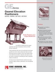
GESeries<br />
GE25 thru GE45<br />
Features<br />
135º powered forward tilt<br />
NEMA 12 Electricals<br />
Powered Geared Elevation<br />
for varying work height<br />
90,000 psi aluminum-bronze<br />
low efficiency wormgear<br />
drive reduces back driving<br />
All steel welded gearboxes<br />
Low voltage hand control<br />
pendants<br />
50:1 Variable speed drives<br />
AC brake motors<br />
The <strong>Koike</strong> Aronson GE25 to GE45 series of Geared Elevation<br />
<strong>Positioner</strong>s are designed for lighter weight applications and portability.<br />
These Geared Elevation <strong>Positioner</strong>s allow work to be performed at<br />
the lowest possible level which makes welding both faster and safer.<br />
Along with precision elevation control, these <strong>Positioner</strong>s allow<br />
simultaneous table tilt and rotation. Operators may easily access any<br />
section of a weldment eliminating the need for ladders and platforms.<br />
Standard hand pendant provided with all models<br />
All <strong>Koike</strong> Aronson Geared Elevating <strong>Positioner</strong>s are engineered for<br />
safety , precision, performance and unsurpassed durability.<br />
Capacities from 2,500 to 4,500 pounds<br />
Optional foot switch controls available<br />
KOIKE ARONSON, INC. / RANSOME<br />
PAGE 26
Specifications<br />
GE25 - GE45<br />
SPECIFICATIONS GE25VF GE30VF GE45VF<br />
Tilt: Load Torque in-lb (N.m)<br />
Rating Lbs.(kg) @ 6” (152mm) CG Height<br />
Rating Lbs.(kg) @ 12” (305mm) CG Height<br />
Rating Lbs.(kg) @ 18” (457mm) CG Height<br />
Rating Lbs.(kg) @ 24” (609mm) CG Height<br />
Rating Lbs.(kg) @ 30” (762mm) CG Height<br />
Rating Lbs.(kg) @ 36” (914mm) CG Height<br />
Rating Lbs.(kg) @ 42” (1067mm) CG Height<br />
Rating Lbs.(kg) @ 48” (1219mm) CG Height<br />
Rating Lbs.(kg) @ 54” (1371mm) CG Height<br />
Rating Lbs.(kg) @ 60” (1524mm) CG Height<br />
Rating Lbs.(kg) @ 66” (1676mm) CG Height<br />
Rating Lbs.(kg) @ 72” (1829mm) CG Height<br />
27,500 (3108)<br />
2,500 (1134)<br />
1,600 (726)<br />
1,200 (544)<br />
950 (431)<br />
780 (354)<br />
670 (304)<br />
580 (263)<br />
520 (236)<br />
460 (209)<br />
420 (190)<br />
380 (172)<br />
350 (159)<br />
60,750 (6864)<br />
-<br />
3,000 (1361)<br />
2,500 (1043)<br />
1,880 (853)<br />
1,600 (726)<br />
1,375 (624)<br />
1,200 (544)<br />
1,075 (488)<br />
975 (442)<br />
890 (404)<br />
820 (372)<br />
750 (340)<br />
91,125 (10297)<br />
-<br />
4,500 (2041)<br />
3,500 (1587)<br />
2,800 (1270)<br />
2,400 (1089)<br />
2,050 (930)<br />
1,800 (816)<br />
1,600 (726)<br />
1,450 (658)<br />
1,300 (590)<br />
1,200 (544)<br />
1,100 (499)<br />
Rotation: Load Torque in-lb (N.m)<br />
Rating Lbs.(kg) @ 6” (152mm) Eccentric<br />
Rating Lbs.(kg) @ 12” (305mm) Eccentric<br />
15,000 (1695)<br />
2,500 (1134)<br />
1,250 (567)<br />
36,000 (4068)<br />
-<br />
3,000 (1361)<br />
54,000 (6102)<br />
-<br />
4,500 (2041)<br />
Tilt: 135º in how many seconds<br />
Tilt Motor Horse Power<br />
19 Sec.<br />
1-½ HP<br />
25 Sec.<br />
2 HP<br />
25 Sec.<br />
3 HP<br />
Rotation: Speed Range 50:1 AC Drive<br />
Rotation Motor Horse Power<br />
2.0 - .040 rpm<br />
1 HP<br />
1.2 – .024 rpm<br />
1-½ HP<br />
1.2 – .024 rpm<br />
2 HP<br />
Elevation: Constant Speed, IPM (mm/min)<br />
Elevation Motor Horse Power<br />
34 (863)<br />
1-½ HP<br />
30 (762)<br />
2 HP<br />
30 (762)<br />
3 HP<br />
Pendant cable length: 20 ft. 20 ft. 20 ft.<br />
C: Table Size<br />
CW: Maximum Clamping Diameter<br />
CX: Number of slots and width<br />
Number of Table nuts and Thread<br />
D: Table Thickness<br />
E: Pilot hole and depth<br />
DE: Inherent Overhang<br />
36” Dia. (914mm)<br />
33-¾” (857)<br />
(4) 25/32” (20mm)<br />
None<br />
1 (25)<br />
1.500 x 1” (38.1 x 25mm)<br />
5 (127)<br />
36”x 36” (914 x 914)<br />
47” (1194)<br />
(4) 13/16” (21mm)<br />
(4) 3/4”-10<br />
1–3/4(44)<br />
9.126 x 1” (232 x 25)<br />
8-1/4 (209)<br />
42”x 42” (1067 x 1067)<br />
55-½” (1410)<br />
(4) 13/16” (21mm)<br />
(4) 3/4”-10<br />
1–3/4(44)<br />
9.126 x 1” (232 x 25)<br />
8-1/4 (209)<br />
Spindle OD Bearing Bore<br />
Hollow Spindle Dia<br />
2-3/8 (60)<br />
1-1/2 (38)<br />
10 (254)<br />
8-½” (216)<br />
10 (254)<br />
8-½” (216)<br />
Weld Current Conduction 1500 Amps 2000 Amps 2000 Amps<br />
F: Table flat, Minimum Height<br />
Table flat, Maximum Height<br />
Lift Stroke<br />
35 (889)<br />
59 (1499)<br />
24” (610)<br />
52-3/4 (1340)<br />
85-3/4 (2178)<br />
33” (838)<br />
52-3/4 (1340)<br />
85-3/4 (2178)<br />
33” (838)<br />
G: Rotation axis, Minimum Height<br />
Rotation axis, Maximum Height<br />
30” (762)<br />
54” (1372)<br />
44-½” (1130)<br />
77-½” (1968)<br />
44-½” (1130)<br />
77-½” (1968)<br />
I: Tie down hole size<br />
J: Front Mounting hole location<br />
K: Rear mounting hole location<br />
L: Rear bolt hole pattern pitch<br />
M: Overall base length<br />
N: Overall Base width<br />
O: Overall machine length<br />
(4) 13/16” (20.6mm)<br />
1” (25)<br />
53” (1346)<br />
41-1/2 (1054)<br />
55 (1397)<br />
43 (1092)<br />
68-1/2 (1740)<br />
(4) 13/16” (20.6mm)<br />
3 (76)<br />
73” (1854)<br />
46” (1168)<br />
79 (2007)<br />
50 (1270)<br />
89-1/2 (2273)<br />
(4) 13/16” (20.6mm)<br />
3 (76)<br />
73” (1854)<br />
46” (1168)<br />
79 (2007)<br />
50 (1270)<br />
92-1/2 (2349)<br />
Standard Primary Voltage 460/3/60 460/3/60 460/3/60<br />
Shipping Weight 2700 lbs. (1225 kg) 5400 lbs (2449 kg) 5622 lbs (2550)<br />
***All dimensions are for reference only and subject to change without notice.<br />
<strong>Koike</strong> Aronson Inc.<br />
P.O. Box 307, Arcade, New York 14009<br />
Phone (585) 492-2400 Fax (585) 457-3517<br />
www.koike.com<br />
PAGE 27
GESeries<br />
GE60 Thru GE250<br />
Features<br />
135º powered forward tilt<br />
NEMA 12 Electricals<br />
Powered Geared Elevation<br />
for varying work height<br />
90,000 psi aluminum-bronze<br />
low efficiency wormgear<br />
drive reduces back driving<br />
All steel welded gearboxes<br />
Low voltage hand control<br />
pendants<br />
50:1 Variable speed drives<br />
AC brake motors<br />
The GE60 to GE250 Models are <strong>Koike</strong> Aronson’s midrange lineup<br />
and are the most popular series with their large capacities and yet<br />
compact size.<br />
Geared Elevation <strong>Positioner</strong>s allow work to be performed at the<br />
lowest possible level which makes welding both faster and safer. Along<br />
with precision elevation control, these <strong>Positioner</strong>s enable simultaneous<br />
tilt and rotation. Operators may easily access any section of a<br />
weldment, eliminating the need for ladders and platforms.<br />
All <strong>Koike</strong> Aronson / Ransome Geared Elevating <strong>Positioner</strong>s are<br />
engineered for safety, precision, performance and unsurpassed<br />
durability.<br />
Standard hand pendant provided with all models<br />
Capacities from 6,000 to 25,000 pounds<br />
Optional foot switch controls available<br />
KOIKE ARONSON, INC. / RANSOME<br />
PAGE 28
Specifications<br />
GE60 - GE250<br />
SPECIFICATIONS GE60VF GE90VF GE120VF GE180VF GE250VF<br />
Tilt: Load Torque in-lb (N.m)<br />
Rating Lbs.(kg) @ 6” (152mm) CG Height<br />
Rating Lbs.(kg) @ 12” (305mm) CG Height<br />
Rating Lbs.(kg) @ 18” (457mm) CG Height<br />
Rating Lbs.(kg) @ 24” (609mm) CG Height<br />
Rating Lbs.(kg) @ 30” (762mm) CG Height<br />
Rating Lbs.(kg) @ 36” (914mm) CG Height<br />
Rating Lbs.(kg) @ 42” (1067mm) CG Height<br />
Rating Lbs.(kg) @ 48” (1219mm) CG Height<br />
Rating Lbs.(kg) @ 54” (1371mm) CG Height<br />
Rating Lbs.(kg) @ 60” (1524mm) CG Height<br />
Rating Lbs.(kg) @ 66” (1676mm) CG Height<br />
Rating Lbs.(kg) @ 72” (1829mm) CG Height<br />
123,000 (13899)<br />
-<br />
6,000 (2721)<br />
4,650 (2109)<br />
3,790 (1719)<br />
3,200 (1451)<br />
2,750 (1247)<br />
2,400 (1089)<br />
2,200 (998)<br />
1,900 (862)<br />
1,700 (771)<br />
1,600 (726)<br />
1,500 (680)<br />
184,500 (20848)<br />
-<br />
9,000 (4082)<br />
7,000 (3175)<br />
5,700 (2585)<br />
4,800 (2177)<br />
4,150 (1882)<br />
3,650 (1656)<br />
3,250 (1474)<br />
2,950 (1338)<br />
2,700 (1225)<br />
2,480 (1125)<br />
2,300 (1043)<br />
252,000 (28476)<br />
-<br />
12,000 (5443)<br />
9,300 (4218)<br />
7,600 (3447)<br />
6,450 (2926)<br />
5,600 (2540)<br />
4,950 (2245)<br />
4,400 (1996)<br />
4,000 (1814)<br />
3,650 (1656)<br />
3,350 (1519)<br />
3,100 (1406)<br />
369,500 (41753)<br />
-<br />
18,000 (8165)<br />
13,900 (6304)<br />
11,350 (5148)<br />
9,600 (4354)<br />
8,300 (3765)<br />
7,300 (3311)<br />
6,500 (2948)<br />
5,900 (2676)<br />
5,400 (2449)<br />
4,950 (2245)<br />
4,600 (2086)<br />
512,500 (57912)<br />
-<br />
25,000 (11340)<br />
19,400 (8800)<br />
15,800 (7167)<br />
13,300 (6033)<br />
11,500 (5216)<br />
10,200 (4627)<br />
9,000 (4082)<br />
8,200 (3719)<br />
7,500 (3402)<br />
6,900 (3130)<br />
6,400 (2903)<br />
Rotation: Load Torque in-lb (N.m)<br />
Rating Lbs.(kg) @ 6” (152mm) Eccentric<br />
Rating Lbs.(kg) @ 12” (305mm) Eccentric<br />
72,000 (8136)<br />
-<br />
6,000 (2721)<br />
108,000 (12204)<br />
-<br />
9,000 (4082)<br />
144,000 (16272)<br />
-<br />
12,000 (5443)<br />
216,000 (24408)<br />
-<br />
18,000 (8165)<br />
300,000 (33900)<br />
-<br />
25,000 (11340)<br />
Tilt: 135º in how many seconds<br />
Tilt Motor Horse Power<br />
35 Sec.<br />
3 HP<br />
47 Sec.<br />
3 HP<br />
63 Sec.<br />
3 HP<br />
47 Sec.<br />
7-½ HP<br />
47 Sec.<br />
10 HP<br />
Rotation: Speed Range 50:1 AC Drive<br />
Rotation Motor Horse Power<br />
1.5 - .030 rpm<br />
5 HP<br />
1.0 - .020 rpm<br />
3 HP<br />
0.8 - .016 rpm<br />
5 HP<br />
0.6 - .012 rpm<br />
5 HP<br />
0.6 - .012 rpm<br />
10 HP<br />
Elevation: Constant Speed, IPM (mm/min)<br />
Elevation Motor Horse Power<br />
24 (610)<br />
3 HP<br />
21 (533)<br />
3 HP<br />
18 (457)<br />
5 HP<br />
24 (610)<br />
7-½ HP<br />
20 (508)<br />
10 HP<br />
Pendant cable length: 20 ft. 20 ft. 20 ft. 20 ft. 20 ft.<br />
C: Table Size<br />
CW: Maximum Clamping Diameter<br />
CX: Number of slots and width<br />
Number of Table nuts and Thread<br />
D: Table Thickness<br />
E: Pilot hole and depth<br />
DE: Inherent Overhang<br />
48” x 48” (1219 x 1219)<br />
64 (1626)<br />
(4) 13/16” (21mm)<br />
(4) ¾-10<br />
2 (51)<br />
9.126” x 1” (232 x 25)<br />
8-½” (216)<br />
48” x 48” (1219 x 1219)<br />
64 (1626)<br />
(4) 13/16” (21mm)<br />
(4) ¾-10<br />
2 (51)<br />
9.126” x 1 (232 x 25)<br />
8-½” (216)<br />
54” x 54” (1372 x 1372)<br />
70 (1778)<br />
(4) 1-1/16” (27mm)<br />
(4) 1”-8<br />
2-½” (63)<br />
9.127” x 1-½” (232 x 38)<br />
8-½” (216)<br />
54” x 54” (1372 x 1372)<br />
70 (1778)<br />
(4) 1-1/16” (27mm)<br />
(4) 1”-8<br />
2-½” (63)<br />
9.127” x 1-½” (232 x 38)<br />
8-½” (216)<br />
60” x 60” (1524 x 1524)<br />
79 (2007)<br />
(4) 1-1/16” (27mm)<br />
(4) 1”-8<br />
2-½” (63)<br />
8.625” x 1-½” (219 x 38)<br />
8-1/2 (216)<br />
Spindle OD Bearing Bore<br />
Hollow Spindle Dia<br />
10 (254)<br />
8-½” (216)<br />
10 (254)<br />
9 (229)<br />
10 (254)<br />
9 (229)<br />
10 (254)<br />
9 (229)<br />
10 (254)<br />
8-1/2 (216)<br />
Weld Current Conduction 2,000 Amps 2,000 Amps 2,000 Amps 2,000 Amps 2,000 Amps<br />
F: Table flat, Minimum Height<br />
Lift Stroke<br />
Table flat, Maximum Height<br />
55” (1397mm)<br />
32-½” (826mm)<br />
87-½” (2222mm)<br />
54-¼” (1384mm)<br />
33” (838mm)<br />
87-½” (2222mm)<br />
55-½” (1410mm)<br />
32-½” (826mm)<br />
88” (2235mm)<br />
55-½” (1410mm)<br />
32-½” (826mm)<br />
88” (2235mm)<br />
57-½” (1460mm)<br />
33” (838mm)<br />
90-½” (2299mm)<br />
G: Rotation axis, Minimum Height<br />
Rotation axis, Maximum Height<br />
46-½” (1181mm)<br />
79” (2007mm)<br />
46” (1168mm)<br />
79” (2007mm)<br />
47” (826mm)<br />
79-½” (2019mm)<br />
47” (826mm)<br />
79-½” (2019mm)<br />
49” (1245mm)<br />
82” (2083mm)<br />
I: Tie down hole size<br />
J: Front Mounting hole location<br />
K: Rear mounting hole location<br />
L: Rear bolt hole pattern pitch<br />
M: Overall base length<br />
N: Overall Base with<br />
O: Overall machine length<br />
(4) 13/16” (21mm)<br />
3” (76mm)<br />
74” (1880mm)<br />
41” (1041mm)<br />
80” (2032mm)<br />
44” (1118mm)<br />
96-5/8” (2454mm)<br />
(4) 13/16” (21mm)<br />
3” (76mm)<br />
74” (1880mm)<br />
41” (1041mm)<br />
80” (2032mm)<br />
44” (1118mm)<br />
96-5/8” (2454mm)<br />
(4) 1–1/8” (28mm)<br />
3” (76mm)<br />
74” (1880mm)<br />
47” (1194mm)<br />
80” (2032mm)<br />
54” (1372mm)<br />
101-½” (2578mm)<br />
(4) 1 1/8” (28mm)<br />
3” (76mm)<br />
74” (1880mm)<br />
47” (1194mm)<br />
80” (2032mm)<br />
54” (1372mm)<br />
100” (2540mm)<br />
(4) 1 1/16” (27mm)<br />
3-3/8” (86mm)<br />
89 ½” (2273mm)<br />
80” (2032mm)<br />
94-½” (2400mm)<br />
88-½” (2248mm)<br />
133” (3378mm)<br />
Standard Primary Voltage 460/3/60 460/3/60 460/3/60 460/3/60 460/3/60<br />
Shipping Weight 7670 lbs. (3479kg) 7700 lbs. (3492kg) 9500 lbs. (4309kg) 9,960 lbs. (4518kg) 17,520 lbs. (7946kg)<br />
***All dimensions are for reference only and subject to change without notice.<br />
<strong>Koike</strong> Aronson Inc.<br />
P.O. Box 307, Arcade, New York 14009<br />
Phone (585) 492-2400 Fax (585) 457-3517<br />
www.koike.com<br />
PAGE 29
GESeries<br />
GE500 Thru GE3500<br />
Features<br />
135º powered forward tilt<br />
NEMA 12 Electricals<br />
Powered Geared Elevation<br />
for varying work height<br />
90,000 psi aluminum-bronze<br />
low efficiency wormgear<br />
drive reduces back driving<br />
All steel welded gearboxes<br />
Low voltage hand control<br />
pendants<br />
50:1 Variable speed drives<br />
AC brake motors<br />
The GE500 to GE3500 Models offer the largest capacities and<br />
range of elevations in the line of <strong>Koike</strong> Aronson <strong>Positioner</strong>s.<br />
Geared Elevation <strong>Positioner</strong>s allow work to be performed at the<br />
lowest possible level which makes welding both faster and safer.<br />
Along with precision elevation control, these <strong>Positioner</strong>s enable<br />
simultaneous tilt and rotation. Operators may easily access any<br />
section of a weldment, eliminating the need for ladders and<br />
platforms.<br />
All <strong>Koike</strong> Aronson / Ransome Geared Elevating <strong>Positioner</strong>s are<br />
engineered for safety, precision, performance and unsurpassed<br />
durability.<br />
Standard hand pendant provided with all models<br />
Capacities from 50,000 to 350,000 pounds<br />
Optional foot switch controls available<br />
KOIKE ARONSON, INC. / RANSOME<br />
PAGE 30
Specifications<br />
GE500 - GE3500<br />
SPECIFICATIONS GE500VF GE850VF GE1200VF GE3500VF<br />
Tilt: Load Torque in-lb (N.m)<br />
Rating Lbs.(kg) @ 12” (305mm) CG Height<br />
Rating Lbs.(kg) @ 18” (457mm) CG Height<br />
Rating Lbs.(kg) @ 24” (609mm) CG Height<br />
Rating Lbs.(kg) @ 30” (762mm) CG Height<br />
Rating Lbs.(kg) @ 36” (914mm) CG Height<br />
Rating Lbs.(kg) @ 42” (1067mm) CG Height<br />
Rating Lbs.(kg) @ 48” (1219mm) CG Height<br />
Rating Lbs.(kg) @ 54” (1371mm) CG Height<br />
Rating Lbs.(kg) @ 60” (1524mm) CG Height<br />
Rating Lbs.(kg) @ 66” (1676mm) CG Height<br />
Rating Lbs.(kg) @ 72” (1829mm) CG Height<br />
1,050,000 (118650)<br />
50,000 (22680)<br />
39,000 (17690)<br />
32,000 (14515)<br />
27,000 (12247)<br />
23,400 (10614)<br />
20,600 (9344)<br />
18,500 (8391)<br />
16,700 (7575)<br />
15,200 (6895)<br />
14,000 (6350)<br />
13,000 (5896)<br />
1,800,000 (203400)<br />
85,000 (38950)<br />
66,100 (30014)<br />
54,091 (24557)<br />
45,769 (20779)<br />
39,667 (18009)<br />
35,000 (15890)<br />
31,316 (14217)<br />
28,333 (12863)<br />
25,870 (11745)<br />
23,800 (10805)<br />
22,000 (9979)<br />
2,880,000 (325440)<br />
120,000 (54431)<br />
96,000 (43545)<br />
80,000 (36287)<br />
68,600 (31116)<br />
60,000 (27215)<br />
53,400 (24222)<br />
48,000 (21772)<br />
43,600 (19777)<br />
40,000 (18144)<br />
37,000 (16783)<br />
34,200 (15513)<br />
9,300,000 (1050900)<br />
350,000 (158757)<br />
286,000 (129727)<br />
240,000 (108862)<br />
210,000 (95254)<br />
184,000 (83461)<br />
160,000 (72575)<br />
145,000 (65771)<br />
135,000 (61235)<br />
125,000 (56699)<br />
115,000 (52163)<br />
107,000 (48534)<br />
Rotation: Load Torque in-lb (N.m)<br />
Rating Lbs.(kg) @ 12” (305mm) Eccentric<br />
600,000 (67800)<br />
50,000 (22680)<br />
1,020,000 (115260)<br />
85,000 (38555)<br />
1,440,000 (162780)<br />
120,000 (54431)<br />
2,640,000 (298320)<br />
220,000 (99790)<br />
Tilt: 135º in how many seconds<br />
Tilt Motor Horse Power<br />
67 Sec.<br />
15 HP<br />
140 Sec.<br />
15 HP<br />
156 Sec.<br />
25 HP<br />
300 Sec.<br />
25 HP<br />
Rotation: Speed Range 50:1 AC Drive<br />
Rotation Motor Horse Power<br />
0.50 - .010 rpm<br />
15 HP<br />
0.40 - .008 rpm<br />
20 HP<br />
0.40 - .008 rpm<br />
25 HP<br />
0.35 - .007 rpm<br />
40 HP<br />
Elevation: Constant Speed, IPM (mm/min)<br />
Elevation Motor Horse Power<br />
20 (508)<br />
20 HP<br />
17 (432)<br />
25 HP<br />
15 (381)<br />
40 HP<br />
10 (254)<br />
150 HP<br />
Pendant cable length: 20 ft. 20 ft. 20 ft. 20 ft.<br />
C: Table Size<br />
CW: Maximum Clamping Diameter<br />
CX: Number of slots and width<br />
Number of Table nuts and Thread<br />
D: Table Thickness<br />
E: Pilot hole and depth<br />
DE: Inherent Overhang<br />
84” x 84” (2134x2134mm)<br />
112” (2845mm)<br />
(4) 1 5/16” (33mm)<br />
(4) 1 ¼” -7<br />
2-¾ “ (70mm)<br />
12.253”x1-¾” (311”x45mm)<br />
8-¾ “ (222mm)<br />
96” x 96” (3048x3048mm)<br />
128” (3251mm)<br />
(8) 1 5/8” (41mm)<br />
(8) 1 ½” -12<br />
3“ (76mm)<br />
12.255”x1 3/8”<br />
9 “ (229mm)<br />
120” x 120” (3048x3048mm)<br />
159” (4039mm)<br />
(8) 1 7/8 ” (48mm)<br />
(8) 1 ¾” -12<br />
5“ (127mm)<br />
12.255”x1”<br />
12“ (305mm)<br />
168” x 168” (4267x4267mm)<br />
224” (5690mm)<br />
(8) 2 1/8” (54mm)<br />
(8) 2” -8<br />
5-½“ (140mm)<br />
20.000”x3”<br />
14-½“ (368mm)<br />
Spindle OD Bearing Bore<br />
Hollow Spindle Dia<br />
14” (356mm)<br />
11-7/8” (301)<br />
14” (356mm)<br />
11-7/8” (301)<br />
14&20” (356 & 508mm)<br />
11/7/8” (301)<br />
100” (2540mm) O.D.<br />
Slew Ring<br />
Weld Current Conduction 3,000 Amps 3,000 Amps 3,000 Amps 3,000 Amps<br />
F: Table flat, Minimum Height<br />
Lift Stroke<br />
Table flat, Maximum Height<br />
58-½” (1486mm)<br />
33” (838mm)<br />
94-½” (2400mm)<br />
82” (2083mm)<br />
54” (1372mm)<br />
136” (3454mm)<br />
98” (2489mm)<br />
54” (1372mm)<br />
152” (3861mm)<br />
144” (3658mm)<br />
92” (2337mm)<br />
236” (5994mm)<br />
G: Rotation axis, Minimum Height<br />
Rotation axis, Maximum Height<br />
52-¾” (1340mm)<br />
85-¾” (2178mm)<br />
73” (1854mm)<br />
127” (3226mm)<br />
86” (2184mm)<br />
140” (3556mm)<br />
129-½” (3289mm)<br />
221-½” (5626mm)<br />
I: Tie down hole size<br />
J: Front Mounting hole location<br />
K: Rear mounting hole location<br />
L: Rear bolt hole pattern pitch<br />
M: Overall base length<br />
N: Overall Machine width<br />
O: Overall machine length<br />
(2) 1-1/16” (27)<br />
None<br />
96” (2438mm)<br />
98-½” (2501mm)<br />
98-¼” (2495mm)<br />
127-½” (3238mm)<br />
134-¾” (3423mm)<br />
None<br />
None<br />
None<br />
None<br />
148 ¾” (3778mm)<br />
137 ½” (3492mm)<br />
196-¾” (4997mm)<br />
None<br />
None<br />
None<br />
None<br />
148 ¾” (3778mm)<br />
141 ½” (3594mm)<br />
209” (5309mm)<br />
None<br />
None<br />
None<br />
None<br />
297” (7544mm)<br />
184” (4674mm)<br />
363” (9220mm)<br />
***All dimensions are for<br />
reference only and subject to<br />
change without notice.<br />
Standard Primary Voltage 460/3/60 460/3/60 460/3/60 460/3/60<br />
Shipping Weight 30,819 lbs. (13979kg) 41,000 lbs. (18597kg) 53,000 lbs. (24040kg) 234,000 lbs. (106141kg)<br />
<strong>Koike</strong> Aronson Inc.<br />
P.O. Box 307, Arcade, New York 14009<br />
Phone (585) 492-2400 Fax (585) 457-3517<br />
www.koike.com<br />
PAGE 31
PESeries<br />
25P/E thru 250P/E<br />
Features<br />
135º powered forward tilt<br />
NEMA 12 Electricals<br />
Powered Screw Jack<br />
Elevation<br />
High capacity mechanical<br />
grounding shoes<br />
Spur gear final drive on tilt<br />
and rotation axis<br />
Low voltage hand control<br />
pendants<br />
The 25/PE - 250/PE series <strong>Positioner</strong>s provide all of the same<br />
benefits of the GE models but at a more affordable cost.<br />
The Powered Elevation design makes maximum use of proven<br />
commercially available components, both in the elevation and guidance<br />
systems.<br />
Elevation is made possible by means of commercial ball screw<br />
jacks for high duty cycle operation, driven by a worm/wormgear<br />
arrangement. Elevation uses two of these screw jacks for redundancy,<br />
coupled together and driven by a common motor. Belts, chains, and<br />
transfer gears are no longer utilized in the design.<br />
Guidance is by means of wide, large diameter cam followers<br />
bearing on flat guide-ways. Cam follower contact with the guide-ways<br />
is adjustable for wear. Guidance is provided in the front, back, and at<br />
the sides of two columns that rigidly support the cantilevered load.<br />
50:1 Variable speed drives<br />
AC brake motors<br />
Standard hand pendant provided with all models<br />
Capacities from 2,500 to 25,000 pounds<br />
Optional foot switch controls available<br />
KOIKE ARONSON, INC. / RANSOME<br />
PAGE 32
Specifications<br />
25P/E- 250P/E<br />
SPECIFICATIONS 25 P/E (6x6) 40 P/E (6x6) 60 P/E 100 P/E 200 P/E<br />
250 P/E<br />
Tilt: Load Torque in-lb (N.m)<br />
Rating Lbs.(kg) @ 6” (152mm) CG Height<br />
Rating Lbs.(kg) @ 12” (305mm) CG Height<br />
Rating Lbs.(kg) @ 18” (457mm) CG Height<br />
Rating Lbs.(kg) @ 24” (609mm) CG Height<br />
Rating Lbs.(kg) @ 30” (762mm) CG Height<br />
Rating Lbs.(kg) @ 36” (914mm) CG Height<br />
Rating Lbs.(kg) @ 42” (1067mm) CG Height<br />
Rating Lbs.(kg) @ 48” (1219mm) CG Height<br />
Rating Lbs.(kg) @ 54” (1371mm) CG Height<br />
Rating Lbs.(kg) @ 60” (1524mm) CG Height<br />
Rating Lbs.(kg) @ 66” (1676mm) CG Height<br />
Rating Lbs.(kg) @ 72” (1829mm) CG Height<br />
30,000 (3390)<br />
2,500 (1134)<br />
1,700 (771)<br />
1,285 (583)<br />
1,035 (469)<br />
875 (397)<br />
750 (340)<br />
650 (295)<br />
580 (263)<br />
520 (236)<br />
470 (213)<br />
430 (195)<br />
400 (181)<br />
52,000 (5876)<br />
4,000 (1814)<br />
2,737 (1242)<br />
2,080 (944)<br />
1,677 (761)<br />
1,405 (637)<br />
1,210 (549)<br />
1,061 (481)<br />
945 (428)<br />
852 (386)<br />
776 (352)<br />
712 (323)<br />
658 (298)<br />
126,000 (13899)<br />
-<br />
6,000 (2721)<br />
4,650 (2109)<br />
3,790 (1719)<br />
3,200 (1451)<br />
2,750 (1247)<br />
2,400 (1089)<br />
2,200 (998)<br />
1,900 (862)<br />
1,700 (771)<br />
1,600 (726)<br />
1,500 (680)<br />
215,000 (23166)<br />
-<br />
9,500 (4309)<br />
7,500 (3402)<br />
6,200 (2812)<br />
5,250 (2381)<br />
4,600 (2086)<br />
4,050 (1837)<br />
3,650 (1656)<br />
3,300 (1497)<br />
3,000 (1361)<br />
2,700 (1225)<br />
2,500 (1134)<br />
420,000 (47460)<br />
-<br />
20,000 (9071)<br />
15,555 (7055)<br />
12,727 (5772)<br />
10,769 (4884)<br />
9,333 (4233)<br />
8,235 (3735)<br />
7,368 (3342)<br />
6,666 (3023)<br />
6,087 (2761)<br />
5,600 (2450)<br />
5,185 (2351)<br />
525,000 (59325)<br />
-<br />
25,000 (11340)<br />
19,445 (8820)<br />
15,910 (7216)<br />
13,460 (6105)<br />
11,600 (5261)<br />
10,300 (4672)<br />
9,210 (4177)<br />
8,300 (3764)<br />
7,600 (3447)<br />
7,000 (3175)<br />
3,110 (1410)<br />
Rotation: Load Torque in-lb (N.m)<br />
Rating Lbs.(kg) @ 6” (152mm) Eccentric<br />
Rating Lbs.(kg) @ 12” (305mm) Eccentric<br />
15,000 (1695)<br />
2,500 (1134)<br />
1,250 (567)<br />
24,000 (2712)<br />
4,000 (1814)<br />
2,000 (907)<br />
72,000 (8136)<br />
-<br />
6,000 (2721)<br />
120,000 (13560)<br />
10,000 (4535)<br />
9,500 (4309)<br />
240,000 (27120)<br />
-<br />
20,000 (9071)<br />
300,000 (33900)<br />
-<br />
25,000 (11340)<br />
Tilt: Forward Tilt Degrees 135 Degrees 135 Degrees 135 Degrees 135 Degrees 135 Degrees<br />
Rotation: Speed Range 50:1 AC Drive 1.5 - .030 rpm 1.24 - .025 rpm 1.0 - .020 rpm 0.8—.016 rpm 0.49—.010 rpm<br />
Pendant cable length: 20 ft. 20 ft. 20 ft. 20 ft. 20 ft.<br />
135 Degrees<br />
0.49—.010 rpm<br />
20 ft.<br />
C: Table Size<br />
CX: Number of slots and width<br />
Number of Table nuts and Thread<br />
D: Table Thickness<br />
E: Pilot hole and depth<br />
DE: Inherent Overhang<br />
32” Dia. (812mm)<br />
(4) 11/16” (17.5mm)<br />
(4) 5/8”-11<br />
¾”“ (19mm)<br />
4.250”x ¼” (108”x6mm)<br />
6 “ (152.4mm)<br />
42” Dia. (1067mm)<br />
(4) 11/16” (17.5mm)<br />
(4) 5/8”-11<br />
7/8”“ (22mm)<br />
4.625”x 5/16”<br />
7” (178mm)<br />
60” Dia. (1524mm)<br />
(4) 1-1/8” (28.5mm)<br />
(4) 1”-12<br />
¾”“ (19mm)<br />
6.250”x 1/2”<br />
10-¼” (260mm)<br />
60” Dia. (1524mm)<br />
(4) 1-1/8” (28.5mm)<br />
(4) 1”-12<br />
¾”“ (19mm)<br />
9.125”x 3/8”<br />
10-5/8” (270mm)<br />
60” Dia. (1524mm)<br />
(4) 1-1/8” (28.5mm)<br />
(4) 1”-12<br />
¾”“ (19mm)<br />
10.250”x 1/2”<br />
9” (228.6mm)<br />
60” Dia. (1524mm)<br />
(4) 1-1/8” (28.5mm)<br />
(4) 1”-12<br />
1“ (25mm)<br />
10.250”x 1/8”<br />
9” (228.6mm)<br />
Hollow Spindle Dia 2” (50.8mm) 2” (50.8mm) 6” (152.4mm) 6” (152.4mm) 7-½” (190.5mm)<br />
Weld Current Conduction 1,500 Amps 1,500 Amps 2,000 Amps 2,000 Amps 2,000 Amps<br />
7-½” (190.5mm)<br />
2,000 Amps<br />
F: Table flat, Minimum Height<br />
Lift Stroke<br />
Table flat, Maximum Height<br />
38” (965mm)<br />
24” (609mm)<br />
62” (1575mm)<br />
42-½” (1080mm)<br />
24” (609mm)<br />
66-½” (1689mm)<br />
49-¾” (1263mm)<br />
24” (609mm)<br />
73-¾” (1873mm)<br />
69-¼” (1759mm)<br />
26” (660mm)<br />
95-¼” (2419mm)<br />
59” (1499mm)<br />
24” (610mm)<br />
83” (2108mm)<br />
62.5” (1588mm)<br />
24” (610mm)<br />
86.5” (2197mm)<br />
G: Rotation axis, Minimum Height<br />
Rotation axis, Maximum Height<br />
32” (813mm)<br />
56” (1422mm)<br />
35-½” (902mm)<br />
59-½” (1511mm)<br />
39-½” (1003mm)<br />
63-½” (1613mm)<br />
58-5/8” (1489mm)<br />
84-5/8” (2150mm)<br />
50” (1270mm)<br />
74” (1880mm)<br />
50” (1270mm)<br />
74” (1880mm)<br />
I: Tie down hole size<br />
J: Front Mounting hole location<br />
K: Rear mounting hole location<br />
L: Rear bolt hole pattern pitch<br />
M: Overall base length<br />
N: Overall Base with<br />
(6) 1-1/8” (28.5mm)<br />
3-½” (89mm)<br />
44” (1117mm)<br />
9-¾” - 19-½”<br />
50-7/8” (1292mm)<br />
51-¾” (1315mm)<br />
(4) 13/16” (20.6mm)<br />
1-½” (38.1mm)<br />
65-½” (1663mm)<br />
60-¼” (1530mm)<br />
68-½” (1740mm)<br />
63-¾” (1620mm)<br />
(4) 7/8” (22.2mm)<br />
3-½” (89mm)<br />
83-¾” (2127mm)<br />
55” (1397mm)<br />
88-¼” (2242mm)<br />
59” (1499mm)<br />
(4) 7/8” (22.2mm)<br />
3-½” (89mm)<br />
83-¾” (2127mm)<br />
55” (1397mm)<br />
88-¼” (2242mm)<br />
59” (1499mm)<br />
(4) 1-1/8” (28.5mm)<br />
1-½” (38mm)<br />
80-½” (2045mm)<br />
66-½” (1689mm)<br />
83-½” (2121mm)<br />
76-½” (1943mm)<br />
(4) 1-1/8” (28.5mm)<br />
1-½” (38mm)<br />
80-½” (2045mm)<br />
66-½” (1689mm)<br />
83-½” (2121mm)<br />
76-½” (1943mm)<br />
Standard Primary Voltage 460/3/60 460/3/60 460/3/60 460/3/60 460/3/60<br />
Shipping Weight 2700 lbs. (1225kg) 4000 lbs. (1814kg) 6500lbs. (2948kg) 10761 lbs. (4881kg) 16,700 lbs. (7575kg)<br />
460/3/60<br />
17,000 lbs. (7711kg)<br />
***All dimensions are for reference only and subject to change without notice.<br />
<strong>Koike</strong> Aronson Inc.<br />
P.O. Box 307, Arcade, New York 14009<br />
Phone (585) 492-2400 Fax (585) 457-3517<br />
www.koike.com<br />
PAGE 33
FTSeries<br />
FLOOR TURNTABLES<br />
Features<br />
360º powered rotation<br />
NEMA 12 Electricals<br />
Spur gear final drive on<br />
rotation axis<br />
Low voltage hand control<br />
pendants<br />
50:1 Variable speed drives<br />
There are two basic types of Floor Turntables provided by <strong>Koike</strong><br />
Aronson Inc. / Ransome. A free standing “A” frame and free standing<br />
column design are used depending on size and capacity.<br />
Machine capacities of 2,500 Lbs. and less utilize the “A” frame<br />
design. The “A” frame type turntable has a hollow spindle and uses<br />
pre-loaded tapered roller bearings. The bearing housing and main<br />
support “A” frame house the motor and gear reducer below the table,<br />
with no protrusions to prevent interference or damage to parts or<br />
equipment.<br />
Machine capacities of 6,000 Lbs. and more utilize the free<br />
standing column design. The column design floor turntable uses a<br />
large diameter slew ring bearing and center column for supporting the<br />
load. Table deflection is reduced, while direct drive to the gear teeth<br />
on the bearing reduces maintenance.<br />
All <strong>Koike</strong> Aronson Inc. / Ransome floor turntables are variable<br />
speed rotation using variable frequency inverter drives for smooth<br />
acceleration and deceleration control. <strong>Koike</strong> Aronson, Inc. / Ransome<br />
rotation axis are repeatable within ± 0.005 Inches per Inch of radius,<br />
with a consistent load, speed and direction.<br />
AC brake motors<br />
Standard hand pendant provided with all models<br />
Capacities from 250 to 40,000 pounds<br />
Optional foot switch controls available<br />
KOIKE ARONSON, INC. / RANSOME<br />
PAGE 34
Specifications<br />
Floor Turntables<br />
Model FT250 FT500 FT1000 FT2500 FT6000 FT10000 FT20000 FT40000<br />
Load Capacity 250 Lbs. 500 Lbs. 1,000 Lbs 2,500 Lbs. 6,000 Lbs 10,000 Lbs 20,000 Lbs 40,000 Lbs<br />
Allowable load eccentricity 3” 6” 6” 6” 12” 12” 12” 12”<br />
Rotation speed (RPM) .07 - 3.7 .04 - 2.0 .04 - 2.0 .02 - 1.0 .02 - 1.0 .02 - 1.0 .02 - 1.0 0.1 - 0.5<br />
Motor (HP) 1/4HP 1/4HP 1/2HP 3/4HP 3/4HP 3/4HP 1HP 1HP<br />
Height from floor 14" 24" 24" 24" 24" 24" 24" 28"<br />
Rotation bearing type<br />
Timken<br />
w/spindle<br />
Timken<br />
w/spindle<br />
Timken<br />
w/spindle<br />
Timken<br />
w/spindle<br />
Slew Ring Slew Ring Slew Ring Slew Ring<br />
Ground current (Amps) 1,500 1,500 1,500 2,000 2,000 2,000 2,000 2,000<br />
Table Size<br />
16" Dia.<br />
Machined<br />
30" Dia.<br />
Machined<br />
30" Dia.<br />
Machined<br />
42" Dia.<br />
Machined<br />
60" Dia. 60" Dia 60" Dia 72" Dia<br />
Table Thickness 3/8" 5/8" 5/8" 5/8" 3/4" 3/4" 1" 1"<br />
***All dimensions are for reference only and subject to change without notice.<br />
<strong>Koike</strong> Aronson Inc.<br />
P.O. Box 307, Arcade, New York 14009<br />
Phone (585) 492-2400 Fax (585) 457-3517<br />
www.koike.com<br />
PAGE 35
OPTIONS<br />
3 JAW SELF CENTERING<br />
SCROLL CHUCKS<br />
Features<br />
Self Centering<br />
Heavy duty 3-Jaw<br />
Construction<br />
Single handed operation<br />
High quality cast iron body with precision machined guideways and<br />
bearing surfaces, drop forged case hardened scroll plate and hardened<br />
and ground pinions. 1 set of hardened reversible two piece jaws, 1 self<br />
ejecting wrench, 1 set of mounting screws, 2 allen keys and mounting<br />
plate provided.<br />
3 JAW SELF CENTERING<br />
GRIPPER CHUCKS<br />
Removable and reversible<br />
jaws<br />
Low maintenance<br />
Long jaw bites for stability<br />
and safety<br />
Serrated jaws available<br />
The Gripper is a cam operated assembly designed specifically for<br />
the welding industry. The gripper incorporates many features that<br />
make it especially suitable for the welding environment. These<br />
features include single point cam operation of the jaws and adjustable<br />
quick-change reversible jaws that can be positioned for small and<br />
large diameter work pieces. Heavy-duty construction and a completely<br />
enclosed faceplate prevents flux and weld splatter from impairing the<br />
operation of the gripper.<br />
KOIKE ARONSON, INC. / RANSOME<br />
PAGE 36
OPTIONS<br />
SCROLL TYPE<br />
Size<br />
Inside<br />
Clamp<br />
Range<br />
Outside<br />
Clamp Range<br />
D F E d C H h Thread<br />
M<br />
Weight<br />
Lbs.<br />
Mount<br />
Plate/Lbs<br />
3JC6 1.65-5.75 .12-6.30 6-1/4” 5.511” 4.921” 1.653” .1575” 2.539” 1.693” M10 (3) 22<br />
3JC12 2.56-10.43 .39-12.40 12-1/2” 11.26” 10.24” 4.055” .1969” 3.701” 2.244” M16 (6) 121<br />
3JC25 5.51-23.23 1.18-24.80 25” 13.00” 16.03” 9.92” 1.18” 5.905” 3.42” ¾-10 (6) 630<br />
GRIPPER<br />
TYPE<br />
***All dimensions are for reference only and subject to change without notice.<br />
.75x8 Dia<br />
11 Lbs.<br />
1”X14.38<br />
Dia / 28<br />
Lbs.<br />
1”X28<br />
Dia / 175<br />
Lbs.<br />
Model<br />
Clamp<br />
Range<br />
inches<br />
Inside<br />
Clamp<br />
Range<br />
inches<br />
Outside<br />
Clamp<br />
Range<br />
inches<br />
Load<br />
Capacity<br />
Lbs.<br />
Weight<br />
Lbs.<br />
Dimensions<br />
A B C<br />
33 1.75” - 31.25” 5.25”- 31.25” 1.75” - 27.75” 3000 228 18” 7” 19-5/16”<br />
44 1.75” - 44” 5.25” - 44” 1.75” - 40.5” 3000 305 23-1/2” 7” 19-5/16”<br />
63 3.5” - 62.5” 7” - 62.5” 3.5” - 59” 7500 722 34-13/16” 8-1/8” 26-3/4”<br />
***All dimensions are for reference only and subject to change without notice.<br />
<strong>Koike</strong> Aronson Inc.<br />
P.O. Box 307, Arcade, New York 14009<br />
Phone (585) 492-2400 Fax (585) 457-3517<br />
www.koike.com<br />
PAGE 37
OPTIONS<br />
WP-3 JAW SELF CENTERING<br />
CHUCKS<br />
Features<br />
Self Centering<br />
Heavy duty 3-Jaw<br />
Construction<br />
Open center 3 Jaw self centering chuck, allows fast set-up of<br />
cylindrical shapes. Heavy-duty construction and a completely<br />
enclosed faceplate prevents flux and weld splatter from impairing<br />
operation.<br />
Quick lock handles<br />
Low maintenance<br />
Light weight for small<br />
capacity <strong>Positioner</strong>s<br />
Model WP-200 WP-300 WP-400<br />
Inside Clamp Range 3.1—8.7” 4.7”- 11.8” 6.5” - 15”<br />
Outside Clamp<br />
Range<br />
.8—5.1” 2”-7.9”<br />
3.5” - 12.2”<br />
D1 7.8" 11.8" 15.7"<br />
D2 4.7" 5.9" 9.8"<br />
D3 3.1" 3.9" 6.7"<br />
A 1.5" 1.5" 1.8"<br />
B 3/4" 3/4" .98"<br />
G 2.7" 2.7" 3.8"<br />
L 3.0" 3.1" 3.9"<br />
H 1.8" 1.8" 2.6"<br />
F 1.3" 1.4" 1.4"<br />
P 3.9" 4.7" 8.7"<br />
Weight (Lbs.) 13 26 48<br />
***All dimensions are for reference only and subject to change without notice.<br />
KOIKE ARONSON, INC. / RANSOME<br />
PAGE 38
:<br />
OPTIONS<br />
By the nature of design and function, the majority of optional equipment for <strong>Koike</strong> Aronson / Ransome <strong>Positioner</strong>s<br />
should be installed at the time of manufacture. When ordering <strong>Positioner</strong>s, it is therefore important to consider all optional<br />
features and equipment.<br />
Radio Remote Controlled Pendant<br />
The <strong>Koike</strong> Aronson/Ransome Handheld Radio Remote Controlled Pendant<br />
is user friendly and adaptable to any <strong>Positioner</strong>. The weatherproof and<br />
lightweight pendant includes a resettable E-Stop and speed potentiometer for<br />
complete, safe machine control. A magnetic holder allows operator to keep<br />
remote out of harms way when not in use.<br />
Safety Laser Scanner<br />
The <strong>Koike</strong> Aronson/Ransome Safety Laser Scanner increases safety and is<br />
adaptable to any <strong>Positioner</strong>. Tied electronically to the <strong>Positioner</strong>, any intrusion into the<br />
programmed Scan area produces an E-Stop condition. Providing protection for operators<br />
and eliminating part collisions with the floor or other obstacles.<br />
.<br />
Programmable <strong>Positioner</strong> Control<br />
The programmable controller is designed to receive and memorize optimum<br />
work piece positions and increase productivity. The standard programmable<br />
control provides up to 3 part programs with 20 positions. Programmable<br />
<strong>Positioner</strong> System is designed to increase productivity of manual welding<br />
applications as well as aid in the transition from manual to robotic welding<br />
applications. Built in I/O can accept and provide “In position” signals to any<br />
robotic control. There is no need to reprogram <strong>Positioner</strong> welding sequence,<br />
all existing programs can be utilized.<br />
Foot Switch Control<br />
With three styles of foot switches available <strong>Koike</strong> Aronson can adapt your positioner<br />
to be used in the most efficient way.<br />
FSC—Foot Speed control, provides variable speed control through the use of a foot<br />
switch.<br />
FPC—Provides On/Off foot control of the rotational axis.<br />
FWD/REV—Provides forward and reverse foot control of the rotational axis.<br />
(pictured above)<br />
Variable Diameter Tachometer<br />
Reads directly in Inches Per Minute for varying diameters. 2 inputs required,<br />
one is speed (IPM) required and the other is the Diameter vessel being rotated.<br />
Read out can Display IPM or RPM. HMI unit can be located in main electrical<br />
enclosure or stand alone pendant box. Actual running speed sensed by<br />
precision generator.<br />
Special Tables<br />
Many standard table options are available, From round to square, machined or scribed.<br />
Standard t-slot configurations to customer specified bolt hole patterns and pilot<br />
configurations<br />
PAGE 39
CUTTING, POSITIONING & WELDING EQUIPMENT<br />
KOIKE ARONSON, INC. / RANSOME<br />
635 West Main Street<br />
P.O. Box 307,<br />
Arcade, New York 14009<br />
Phone (585) 492-2400<br />
Fax (585) 457-3517<br />
Toll Free: 800-252-5232<br />
www.koike.com<br />
Contact <strong>Koike</strong> Aronson’s World Wide <strong>Positioner</strong> Sales:<br />
1-585-492-2400 x 480<br />
<strong>Positioner</strong>s@koike.com<br />
CATALOG: POSITIONERS 08/13 REV 2