ABB i-Bus® EIB ABB Powernet EIB
ABB i-Bus® EIB ABB Powernet EIB
ABB i-Bus® EIB ABB Powernet EIB

Create successful ePaper yourself
Turn your PDF publications into a flip-book with our unique Google optimized e-Paper software.
Product manual<br />
<strong>ABB</strong> i-bus ® <strong>EIB</strong><br />
<strong>ABB</strong> <strong>Powernet</strong> <strong>EIB</strong><br />
<strong>ABB</strong> i-Bus ® <strong>EIB</strong><br />
<strong>ABB</strong> <strong>Powernet</strong> <strong>EIB</strong><br />
LEANtouch (monochrome),<br />
SMARTtouch (monochrome, colour)<br />
Type: 6136/30M-500, 6136/100M-500,<br />
6136/100C-500, 6136/100CB<br />
6936/30M, 6936/100M,<br />
6936/100C, 6936/100CB<br />
Intelligent Installation Systems<br />
January 2005 1
<strong>ABB</strong> i-bus ® <strong>EIB</strong><br />
<strong>ABB</strong> <strong>Powernet</strong> <strong>EIB</strong><br />
Contents<br />
LEANtouch (monochrome) 6x36/30M(-500) 2 - 4<br />
SMARTtouch (monochrome) 6x36/100M(-500) 2 - 5<br />
SMARTtouch (colour) 6x36/100C(-500) 2 - 6<br />
SMARTtouch B&O 6x36/100CB 2 - 7<br />
Application programs 2 - 8<br />
Circuit diagram 2 - 8<br />
Installation of the supplementary software 2 - 9<br />
Functions of the panel software 2 - 11<br />
Functional description: Basic settings 2 - 14<br />
Functional description: Touch surfaces (Homepage) 2 - 18<br />
Functional description: Touch surfaces (Control page) 2 - 26<br />
Functional description: Time programs 2 - 41<br />
Functional description: IR control 2 - 46<br />
Functional description: Room thermostat 2 - 52<br />
Functional description: Lightscenes 2 - 61<br />
Functional description: Alarm function 2 - 64<br />
Functional description: Presence simulation 2 - 66<br />
Functional description: Logical functions 2 - 67<br />
2 January 2005
<strong>ABB</strong> i-bus ® <strong>EIB</strong><br />
<strong>ABB</strong> <strong>Powernet</strong> <strong>EIB</strong><br />
January 2005 3
<strong>ABB</strong> i-bus ® <strong>EIB</strong><br />
<strong>ABB</strong> <strong>Powernet</strong> <strong>EIB</strong><br />
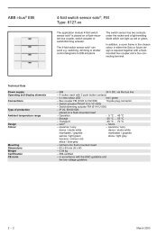
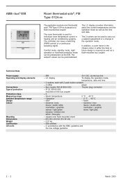
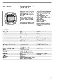
LEANtouch (monochrome)<br />
Type: 6136/30M-500<br />
6936/30M<br />
The LEANtouch panel is a high-quality<br />
<strong>EIB</strong> touch-sensitive display. The panel<br />
offers approx. 30 operator functions<br />
with a monochrome display. It is used<br />
as a control, monitoring and<br />
indication unit for the complete <strong>EIB</strong><br />
installation which can be operated<br />
across different rooms.<br />
The touch-sensitive display is set in a<br />
black, high-gloss frame and has<br />
backlighting available. The integrated<br />
loudspeaker can e.g. feed back<br />
operations acoustically or signal<br />
alarm and fault messages.<br />
The panel has a pen for operation<br />
and a slot for a multimedia/SD card.<br />
The operation and control is carried<br />
out in a clear menu structure via the<br />
touch surfaces which are labelled in<br />
clear text. The functional assignment<br />
of the touch surfaces can be created<br />
individually and is dependent on the<br />
parameterisation.<br />
All the functions of the panel are listed<br />
in the table below “Functional<br />
overview” (see below).<br />
Technical Data<br />
Power supply – Nominal voltage 230 V AC +10%<br />
– Bus voltage (TP only) 24 V DC<br />
– Power consumption 10 W<br />
Operating and display elements – Touch-sensitive display 320 x 240 pixels<br />
16 grey shades (monochrome)<br />
Connections – Power supply Screw plug-in terminals up to 2.5 mm²<br />
– <strong>EIB</strong> bus connection (TP only) Screw plug-in terminals up to 1.5 mm²<br />
– Multimedia/SD card 1 module slot at the front<br />
Type of protection – IP 20, EN 60 529<br />
Protection class<br />
–II<br />
Ambient temperature range – Operation 0 °C to + 45 °C<br />
– Storage and transport - 20 °C to + 60 °C<br />
Dimensions – Panel with cover frame 184.6 x 218 mm (H x W)<br />
– Flush-mounted box 163.5 x 199 x 60 (H x W x D)<br />
Weight<br />
– 0.742 kg<br />
Certification<br />
CE norm<br />
– <strong>EIB</strong>-certified<br />
– in accordance with the EMC guideline<br />
and the low voltage guideline<br />
Functional overview<br />
– Number of touch surfaces 6<br />
(possible control pages) on Homepage<br />
– Number of possible functions per 5<br />
control page<br />
– Total of operator functions 30<br />
– Scope of time programs 5 channels, 5 switching times each<br />
– Scope of scenes 32 scenes with max. 10 objects<br />
(loads)<br />
– Number of alarm signals 5<br />
– Presence simulation max. 10 devices<br />
– IR remote control channels 10<br />
– Integrated room thermostat<br />
– Child protection<br />
– Number of logic functions 10<br />
(AND, OR, NAND, NOR, multiplexer,<br />
multiplier, GATE, temperature comparator)<br />
4 January 2005
<strong>ABB</strong> i-bus ® <strong>EIB</strong><br />
<strong>ABB</strong> <strong>Powernet</strong> <strong>EIB</strong><br />
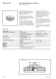
SMARTtouch (monochrome)<br />
Type: 6136/100M-500<br />
6936/100M<br />
The SMARTtouch panel is a highquality<br />
<strong>EIB</strong> touch-sensitive display.<br />
The panel offers approx. 100 operator<br />
functions with a monochrome display.<br />
It is used as a control, monitoring and<br />
indication unit for the complete <strong>EIB</strong><br />
installation which can be operated<br />
across different rooms.<br />
The touch-sensitive display (either in<br />
colour or black/white) is set in a black,<br />
high-gloss frame and has<br />
backlighting available. The integrated<br />
loudspeaker can e.g. feed back<br />
operations acoustically or signal<br />
alarm and fault messages.<br />
The panel has a pen for operation<br />
and a slot for a multimedia/SD card.<br />
The operation and control is carried<br />
out in a clear menu structure via the<br />
touch surfaces which are labelled in<br />
clear text. The functional assignment<br />
of the touch surfaces can be created<br />
individually and is dependent on the<br />
parameterisation.<br />
All the functions of the panel are listed<br />
in the table below “Functional<br />
overview” (see below).<br />
Technical Data<br />
Power supply – Nominal voltage 230 V AC +10%<br />
– Bus voltage (TP only) 24 V DC<br />
– Power consumption 10 W<br />
Operating and display elements – Touch-sensitive display 320 x 240 pixels<br />
16 grey shades (monochrome)<br />
Connections – Power supply Screw plug-in terminals up to 2.5 mm²<br />
– <strong>EIB</strong> bus connection (TP only) Screw plug-in terminals up to 1.5 mm²<br />
– Multimedia/SD card 1 module slot at the front<br />
Type of protection – IP 20, EN 60 529<br />
Protection class<br />
–II<br />
Ambient temperature range – Operation 0 °C to + 45 °C<br />
– Storage and transport - 20 °C to + 60 °C<br />
Dimensions – Panel with cover frame 184.6 x 218 mm (H x W)<br />
– Flush-mounted box 163.5 x 199 x 60 (H x W x D)<br />
Weight<br />
– 0.742 kg<br />
Certification<br />
CE norm<br />
– <strong>EIB</strong>-certified<br />
– in accordance with the EMC guideline<br />
and the low voltage guideline<br />
Functional overview:<br />
– Number of touch surfaces 10<br />
(possible control pages) on Homepage<br />
– Number of possible functions per 10<br />
control page<br />
– Total of operator functions 100<br />
– Scope of time programs 20 channels, 10 switching times each<br />
– Scope of scenes 32 scenes with max. 20 objects<br />
(loads)<br />
– Number of alarm signals 10<br />
– Monitoring function Monitoring of up to 30 signalling<br />
inputs (e.g. window contacts,<br />
movement detectors)<br />
– Presence simulation max. 10 devices<br />
– IR remote control channels 10<br />
– Integrated room thermostat<br />
– Info function<br />
– Timer function<br />
– Child protection<br />
– Number of logic functions 20<br />
(AND, OR, NAND, NOR, multiplexer,<br />
multiplier, GATE, temperature comparator)<br />
January 2005 5
<strong>ABB</strong> i-bus ® <strong>EIB</strong><br />
<strong>ABB</strong> <strong>Powernet</strong> <strong>EIB</strong><br />
SMARTtouch (colour)<br />
Type: 6136/100C-500<br />
6936/100C<br />
The SMARTtouch panel is a highquality<br />
<strong>EIB</strong> touch-sensitive display.<br />
The panel offers approx. 100 operator<br />
functions with a colour display. It is<br />
used as a control, monitoring and<br />
indication unit for the complete <strong>EIB</strong><br />
installation which can be operated<br />
across different rooms.<br />
The touch-sensitive display (either in<br />
colour or black/white) is set in a black,<br />
high-gloss frame and has<br />
backlighting available. The integrated<br />
loudspeaker can e.g. feed back<br />
operations acoustically or signal<br />
alarm and fault messages.<br />
The panel has a pen for operation<br />
and a slot for a multimedia/SD card.<br />
The operation and control is carried<br />
out in a clear menu structure via the<br />
touch surfaces which are labelled in<br />
clear text. The functional assignment<br />
of the touch surfaces can be created<br />
individually and is dependent on the<br />
parameterisation.<br />
All the functions of the panel are listed<br />
in the table below “Functional<br />
overview” (see below).<br />
Technical Data<br />
Power supply – Nominal voltage 230 V AC +10%<br />
– Bus voltage (TP only) 24 V DC<br />
– Power consumption 10 W<br />
Operating and display elements – Touch-sensitive display 320 x 240 pixels<br />
16 grey shades (monochrome)<br />
Connections – Power supply Screw plug-in terminals up to 2.5 mm²<br />
– <strong>EIB</strong> bus connection (TP only) Screw plug-in terminals up to 1.5 mm²<br />
– Multimedia/SD card 1 module slot at the front<br />
Type of protection – IP 20, EN 60 529<br />
Protection class<br />
–II<br />
Ambient temperature range – Operation 0 °C to + 45 °C<br />
– Storage and transport - 20 °C to + 60 °C<br />
Dimensions – Panel with cover frame 184.6 x 218 mm (H x W)<br />
– Flush-mounted box 163.5 x 199 x 60 (H x W x D)<br />
Weight<br />
– 0.742 kg<br />
Certification<br />
CE norm<br />
– <strong>EIB</strong>-certified<br />
– in accordance with the EMC guideline<br />
and the low voltage guideline<br />
Functional overview:<br />
– Number of touch surfaces 10<br />
(possible control pages) on Homepage<br />
– Number of possible functions per 10<br />
control page<br />
– Total of operator functions 100<br />
– Scope of time programs 20 channels, 10 switching times each<br />
– Scope of scenes 32 scenes with max. 20 objects<br />
(loads)<br />
– Number of alarm signals 10<br />
– Monitoring function Monitoring of up to 30 signalling<br />
inputs (e.g. window contacts,<br />
movement detectors)<br />
– Presence simulation max. 10 devices<br />
– IR remote control channels 10<br />
– Integrated room thermostat<br />
– Info function<br />
– Timer function<br />
– Child protection<br />
– Number of logic functions 20<br />
(AND, OR, NAND, NOR, multiplexer,<br />
multiplier, GATE, temperature comparator)<br />
6 January 2005
<strong>ABB</strong> i-bus ® <strong>EIB</strong><br />
<strong>ABB</strong> <strong>Powernet</strong> <strong>EIB</strong><br />
SMARTtouch B&O<br />
Type: 6136/100CB<br />
6936/100CB<br />
Technical Data<br />
The SMARTtouch panel is a highquality<br />
<strong>EIB</strong> touch-sensitive display.<br />
The panel offers approx. 100 operator<br />
functions with a colour display. It is<br />
used as a control, monitoring and<br />
indication unit for the complete <strong>EIB</strong><br />
installation which can be operated<br />
across different rooms.<br />
The touch-sensitive display (either in<br />
colour or black/white) is set in a black,<br />
high-gloss frame and has<br />
backlighting available. The integrated<br />
loudspeaker can e.g. feed back<br />
operations acoustically or signal<br />
alarm and fault messages.<br />
The panel has a pen for operation<br />
and a slot for a multimedia/SD card.<br />
The operation and control is carried<br />
out in a clear menu structure via the<br />
touch surfaces which are labelled in<br />
clear text. The functional assignment<br />
of the touch surfaces can be created<br />
individually and is dependent on the<br />
parameterisation.<br />
The SMARTtouch B&O panel is<br />
identical to the “standard”<br />
SMARTtouch panel. In addition, it can<br />
be controlled remotely via a Bang &<br />
Olufsen remote control Beo4 e.g. to<br />
retrieve a lightscene in the panel. The<br />
SMARTtouch B&O panel can further<br />
also be operated via the Busch-<br />
Jaeger IR remote control.<br />
All the functions of the panel are listed<br />
in the table below “Functional<br />
overview” (see below).<br />
Power supply – Nominal voltage 230 V AC +10%<br />
– Bus voltage (TP only) 24 V DC<br />
– Power consumption 10 W<br />
Operating and display elements – Touch-sensitive display 320 x 240 pixels<br />
256 colours<br />
Connections – Power supply Screw plug-in terminals up to 2.5 mm²<br />
– <strong>EIB</strong> bus connection (TP only) Screw plug-in terminals up to 1.5 mm²<br />
– Multimedia/SD card 1 module slot at the front<br />
Type of protection – IP 20, EN 60 529<br />
Protection class<br />
–II<br />
Ambient temperature range – Operation 0 °C to + 45 °C<br />
– Storage and transport - 20 °C to + 60 °C<br />
Dimensions – Panel with cover frame 184.6 x 218 mm (H x W)<br />
– Flush-mounted box 163.5 x 199 x 60 (H x W x D)<br />
Weight<br />
– 0.742 kg<br />
Certification<br />
CE norm<br />
– <strong>EIB</strong>-certified<br />
– in accordance with the EMC guideline<br />
and the low voltage guideline<br />
Functional overview:<br />
– Number of touch surfaces 10<br />
(possible control pages) on Homepage<br />
– Number of possible functions per 10<br />
control page<br />
– Total of operator functions 100<br />
– Scope of time programs 20 channels, 10 switching times each<br />
– Scope of scenes 32 scenes with max. 20 objects<br />
(loads)<br />
– Number of alarm signals 10<br />
– Monitoring function Monitoring of up to 30 signalling<br />
inputs (e.g. window contacts,<br />
movement detectors)<br />
– Presence simulation max. 10 devices<br />
– IR remote control channels 10<br />
– Integrated room thermostat<br />
– Info function<br />
– Timer function<br />
– Child protection<br />
– Number of logic functions 20<br />
(AND, OR, NAND, NOR, multiplexer,<br />
multiplier, GATE, temperature comparator)<br />
January 2005 7
<strong>ABB</strong> i-bus ® <strong>EIB</strong><br />
<strong>ABB</strong> <strong>Powernet</strong> <strong>EIB</strong><br />
LEANtouch (monochrome),<br />
SMARTtouch (monochrome, colour)<br />
Type: 6x36/30M(-500), 6x36/100x(-500), 6x36/100CB<br />
Application programs Number of Max. number of Max. number of<br />
communication objects group addresses associations<br />
for LEANtouch/SMARTtouch panel Twisted Pair:<br />
Panel TP/1 approx. 500 approx. 4000 approx. 4000<br />
for LEANtouch/SMARTtouch panel <strong>Powernet</strong>:<br />
Panel PL/1 approx. 500 approx. 4000 approx. 4000<br />
Note<br />
If the SMARTtouch panel 6x36/100CB<br />
should be used, there is no separate<br />
entry for it in the ETS or Power-Project<br />
database.<br />
In this case, the SMARTtouch panel<br />
6x36/100C must be used. The<br />
difference between them is that the<br />
SMARTtouch panel 6x36/100CB can<br />
react to signals of the Bang&Olufson<br />
IR remote control Beo4. (See also IR<br />
control)<br />
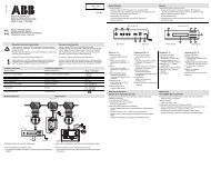
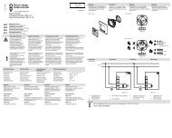
Circuit diagram<br />
1<br />
4<br />
2<br />
3<br />
5<br />
1 Touch-sensitive display 320 x 240 3 MMC/SD card reader<br />
pixels, colour<br />
4 230 V power supply<br />
2 Operating pen 5 24 V <strong>EIB</strong> bus voltage (TP only)<br />
Note<br />
Do not lead any live cables behind the<br />
device through the flush-mounted box.<br />
Separation of the TP bus and mains<br />
cable!<br />
8 January 2005
<strong>ABB</strong> i-bus ® <strong>EIB</strong><br />
<strong>ABB</strong> <strong>Powernet</strong> <strong>EIB</strong><br />
LEANtouch (monochrome),<br />
SMARTtouch (monochrome, colour)<br />
Type: 6x36/30M(-500), 6x36/100x(-500), 6x36/100CB<br />
Installation of the supplementary<br />
software (RCP tool)<br />
To be able to parameterise the LEANtouch<br />
or SMARTtouch panel in ETS 2,<br />
in ETS 3 or in Power-Project (from version<br />
4.0 onwards), the supplementary<br />
software RCP-Tool must be installed.<br />
You can find this software on the <strong>EIB</strong><br />
product database CD-ROM (art. no.<br />
0405) or on the Internet at www.Busch-<br />
Jaeger.de.<br />
The software can be plugged into<br />
ETS 2, ETS 3 and/or Power-Project.<br />
That means that as soon as you<br />
retrieve the parameters of a panel in<br />
ETS or Power-Project, the panel<br />
software is opened automatically in<br />
which you carry out all further settings.<br />
Before you start the installation of<br />
the panel software, please ensure<br />
that ETS or Power-Project has<br />
already been installed on your<br />
computer.<br />
The following section describes the<br />
individual installation steps.<br />
An installation wizard helps you to install<br />
the panel software. This is started<br />
by double clicking on the file<br />
“Setup.exe” and can run in either<br />
“German” or “English”.<br />
Once you have confirmed the welcome<br />
screen with “Next”, you can enter your<br />
name and the name of your company in<br />
the “User info” dialog. If several users<br />
work on the computer on which you<br />
wish to install the software, you can limit<br />
access to the software. This means<br />
that either all the users can start the<br />
software or only you.<br />
The installation path for the panel software<br />
is defined in the next dialog. By<br />
default, this is “C:\Program Files\<strong>EIB</strong>-<br />
Programs\”. It is advisable to keep this<br />
path as e.g. Power-Project has the<br />
same default installation path. All <strong>EIB</strong><br />
programs and additional <strong>EIB</strong> software<br />
can thus be easily located on the hard<br />
disk.<br />
The panel sofware requires at least<br />
Windows 98. You require full administrator<br />
rights of the operating system in order<br />
to install the panel software.<br />
January 2005 9
<strong>ABB</strong> i-bus ® <strong>EIB</strong><br />
<strong>ABB</strong> <strong>Powernet</strong> <strong>EIB</strong><br />
LEANtouch (monochrome),<br />
SMARTtouch (monochrome, colour)<br />
Type: 6x36/30M(-500), 6x36/100x(-500), 6x36/100CB<br />
In the “Select functions” dialog, you define<br />
whether the VD2 or VD3 files should<br />
be copied locally onto the hard disk. You<br />
require these to be able to use the<br />
LEANtouch/SMARTtouch panel in connection<br />
with an ETS version. (Also observe<br />
the note at the end of this chapter).<br />
By default, the files are copied into the<br />
following directory:<br />
C:\Program Files\<strong>EIB</strong>-Programs\RCP-Tool\VDX<br />
To do so, please retrieve the ETS import<br />
tool (ETS 2 or ETS 3) and import<br />
the VD2 (ETS 2) or VD3 files (ETS 3)<br />
from the default directory<br />
C:\Program Files\<strong>EIB</strong>-Programs\RCP-<br />
Tool\VDX.<br />
You must import the VD2 or VD3 files<br />
in full.<br />
Caution:<br />
The import of individual files is not<br />
possible.<br />
Commissioning a panel<br />
The commissioning of a panel is<br />
possible either via a multimedia/SD<br />
card (not included) or with “standard”<br />
bus programming.<br />
Once you have confirmed the “Select<br />
functions” dialog with “Next”, the<br />
installation wizard carries out an<br />
initialisation. This means that all the<br />
required files are compiled together<br />
and stored temporarily. The dialog<br />
“Updating the system” is shown for<br />
visual monitoring purposes.<br />
All the required files are then copied into<br />
the appropriate directories. The installation<br />
is concluded with an automatic<br />
amendment of the Windows registration<br />
entries.<br />
Due to the high level of functionality,<br />
full programming via the bus takes a<br />
long time depending on the<br />
configuration and medium (Twisted<br />
Pair or <strong>Powernet</strong>). The use of the<br />
multimedia/SD card is therefore<br />
recommended for quick and simple<br />
commissioning. It is not advisable to<br />
carry out full bus programming via<br />
<strong>Powernet</strong>.<br />
The menu item “Download” of the commissioning<br />
tool therefore has two further<br />
submenus via which the user can<br />
select the required commissioning method.<br />
If he selects programming via multimedia<br />
card, the configuration is stored<br />
on a card which is connected to the PC.<br />
With a project that is saved in this<br />
way, the panel itself can be<br />
commissioned by inserting the card.<br />
The slot for the multimedia/SD card is<br />
located behind the chrome flap of the<br />
panel.<br />
Several projects can be stored on one<br />
multimedia card. After inserting the<br />
card in the panel, the user can select<br />
the required project which should be<br />
loaded into the panel.<br />
The computer must be restarted depending<br />
on the operating system used.<br />
Note<br />
Once you have installed the panel<br />
software, you must import the product<br />
data (VD2 or VD3 files) in the ETS<br />
database if you wish to parameterise a<br />
panel with ETS.<br />
10 January 2005
<strong>ABB</strong> i-bus ® <strong>EIB</strong><br />
<strong>ABB</strong> <strong>Powernet</strong> <strong>EIB</strong><br />
LEANtouch (monochrome),<br />
SMARTtouch (monochrome, colour)<br />
Type: 6x36/30M(-500), 6x36/100x(-500), 6x36/100CB<br />
Functions of the panel software<br />
If you have inserted a LEANtouch or<br />
SMARTtouch panel in Power-Project<br />
or in ETS, open the panel software by<br />
retrieving the “Edit device” dialog<br />
(Power-Project) or the parameters<br />
(ETS) of the panel. The panel<br />
software starts automatically with the<br />
following interface.<br />
The method of operation of the panel<br />
software is identical to that of Power-<br />
Project or ETS. The “standard” group<br />
addresses and the internal group<br />
addresses are arranged on the lefthand<br />
side. Internal group addresses<br />
are not sent on the bus and are<br />
therefore used to relieve the load on<br />
the bus. A touch surface can for<br />
example be linked with a lightscene<br />
via an internal group address. The<br />
group addresses and the internal<br />
group addresses are linked with the<br />
communication objects in the centre<br />
using drag & drop.<br />
The functions and applications are arranged<br />
with all the communication objects<br />
in the centre. If necessary, the individual<br />
functions/applications must first<br />
be activated so that the communication<br />
objects become visible. The functions<br />
are defined via a pull-down menu.<br />
To obtain a better overview, individual<br />
functions can be temporarily hidden via<br />
the function view.<br />
The buttons at the bottom always jump<br />
directly to the selected function. This is<br />
particularly advisable if the function tree<br />
in the centre has been fully extended.<br />
The parameters of the individual functions<br />
are displayed on the right-hand<br />
side. The parameters of the function that<br />
is marked in the centre are always displayed.<br />
January 2005 11
<strong>ABB</strong> i-bus ® <strong>EIB</strong><br />
<strong>ABB</strong> <strong>Powernet</strong> <strong>EIB</strong><br />
LEANtouch (monochrome),<br />
SMARTtouch (monochrome, colour)<br />
Type: 6x36/30M(-500), 6x36/100x(-500), 6x36/100CB<br />
Functions of the panel software<br />
Copying a panel<br />
Only one panel can be parameterised<br />
at one time. To provide several panels<br />
with the same functionality<br />
(generation of a duplicate of a<br />
previously configured panel), please<br />
proceed as follows:<br />
Retrieve the function “Save as...” from<br />
the File menu. The project is stored<br />
with the file ending *.rcp. Now close<br />
the panel software. Please insert a<br />
new panel in ETS or Power-Project.<br />
This can be in the same or another<br />
project. Then open the panel software<br />
for the inserted panel. Select the<br />
function “Open” in the File menu and<br />
select the previously saved file.<br />
Please note that you can load the<br />
data of a LEANtouch panel into a<br />
SMARTtouch panel but not vice versa.<br />
During the import, the following window<br />
is displayed in which you can select<br />
whether the import should be carried<br />
out with or without group addresses.<br />
Auto backup file<br />
When you retrieve the menu item<br />
“Settings” under the File menu, you<br />
can set the period, after which the<br />
panel software will carry out an<br />
automatic backup. This is a temporary<br />
file which is stored on your hard disk.<br />
If e.g. your computer crashes, you can<br />
retrieve the last automatic backup<br />
with the menu item “Reset” under the<br />
File menu.<br />
Copying functions<br />
To shorten the configuration time, it is<br />
possible to copy the settings of a<br />
function (touch surface, time function,<br />
lightscene). To do so, click on the<br />
function with the right mouse button<br />
which should be copied.<br />
Note:<br />
Only touch surfaces with identical applications<br />
or functions can be duplicated.<br />
During an import with group addresses,<br />
you must ensure that all the group<br />
addresses or actions are already located<br />
in the project with identical EIS types<br />
to the template. Otherwise, you can<br />
only import the data without group<br />
addresses. You must then however link<br />
them again.<br />
12 January 2005
<strong>ABB</strong> i-bus ® <strong>EIB</strong><br />
<strong>ABB</strong> <strong>Powernet</strong> <strong>EIB</strong><br />
LEANtouch (monochrome),<br />
SMARTtouch (monochrome, colour)<br />
Type: 6x36/30M(-500), 6x36/100x(-500), 6x36/100CB<br />
Functions of the panel software<br />
Important note<br />
If you have inserted a LEANtouch/<br />
SMARTtouch panel in ETS 2, you may<br />
no longer retrieve the following<br />
function:<br />
– Shrink database<br />
The reason for this lies in the<br />
database structure of ETS 2. It is not<br />
large enough to take all the panel<br />
information. The panel information is<br />
stored temporarily in several files on<br />
the hard disk. If you carry out the<br />
function mentioned above, the files<br />
are no longer taken into account and<br />
the result is data loss or damage to<br />
the database.<br />
For ETS 2 users:<br />
After importing an ETS 2 project with a<br />
LEANtouch/SMARTtouch panel, a<br />
database consistency check must be<br />
carried out in any case. Otherwise,<br />
the panel is not displayed correctly/<br />
fully within the framework of the<br />
commissioning process.<br />
January 2005 13
<strong>ABB</strong> i-bus ® <strong>EIB</strong><br />
<strong>ABB</strong> <strong>Powernet</strong> <strong>EIB</strong><br />
LEANtouch (monochrome),<br />
SMARTtouch (monochrome, colour)<br />
Type: 6x36/30M(-500), 6x36/100x(-500), 6x36/100CB<br />
Functional description: Basic<br />
settings<br />
Background illumination<br />
The backlighting of the panel is<br />
switched on automatically as soon as<br />
the display is operated. After the<br />
adjustable period “Background<br />
illumination on for”, the lighting is<br />
switched off again provided that the<br />
panel has not been pressed again.<br />
The panel has three communication<br />
objects in the basic settings. All three<br />
objects are used to control the<br />
backlighting and are 1 bit in size.<br />
The backlighting can be switched via<br />
the object “Background illumination”.<br />
A ON telegram received via the <strong>EIB</strong><br />
switches the backlighting on while an<br />
OFF telegram switches it off again.<br />
The object can however also be<br />
linked with an internal address.<br />
Example:<br />
The panel backlighting should always<br />
switch on at 18:00 in the evening and<br />
switch off again at 10:00 in the<br />
morning. To do so, a channel of the<br />
time program function is<br />
parameterised with switching and the<br />
switch object of the channel is linked<br />
with the same internal address as the<br />
background illumination object. The<br />
bus load is reduced on the <strong>EIB</strong> side<br />
due to the internal link and group<br />
addresses or actions are saved.<br />
The object “Status background<br />
illumination” sends an ON telegram<br />
as soon as the backlighting has been<br />
switched on. If the backlighting<br />
switches off again after the set reset<br />
period, the object sends an OFF<br />
telegram.<br />
The backlighting can be disabled via<br />
the object “Enable status”. If an ON<br />
telegram is received, the backlighting<br />
can be switched. If an OFF telegram<br />
is received, the backlighting remains<br />
disabled.<br />
General<br />
By default, the panel has the<br />
languages German and English. The<br />
display language can be set to a third<br />
language via the setting “Countryspecific”.<br />
This third language must be<br />
transferred to the panel via a firmware<br />
update. The additional languages<br />
available can be downloaded from the<br />
Busch-Jaeger homepage<br />
(www.Busch-Jaeger.de).<br />
The panel distinguishes between a<br />
short and long push button action e.g.<br />
when dimming or moving shutters. It<br />
is possible to set the period which the<br />
panel detects as a long push button<br />
action. By default, the period is set at<br />
500 ms.<br />
The panel has an internal<br />
temperature sensor. The measured<br />
value is displayed on the homepage.<br />
The display can also be deactivated<br />
via the setting “Display temperature<br />
indoors”.<br />
The outside temperature is not<br />
displayed by default. The display can<br />
be activated via the display “Display<br />
temperature outdoors”. The outside<br />
temperature is the temperature value<br />
which the panel receives via the<br />
2-byte communication object<br />
“Temperature outside”. It can be<br />
recorded e.g. by a “standard” <strong>EIB</strong><br />
temperature sensor and sent via its<br />
2-byte communication object “Actual<br />
value”.<br />
14 January 2005
<strong>ABB</strong> i-bus ® <strong>EIB</strong><br />
<strong>ABB</strong> <strong>Powernet</strong> <strong>EIB</strong><br />
LEANtouch (monochrome),<br />
SMARTtouch (monochrome, colour)<br />
Type: 6x36/30M(-500), 6x36/100x(-500), 6x36/100CB<br />
If the indoor and outdoor temperature<br />
should be displayed simultaneously,<br />
the corresponding point on the<br />
display changes every 5 s.<br />
The panel can display the date and<br />
time. The display can be carried out in<br />
the German format (TT.MM.JJJJ; 24h)<br />
or in the English format (MM.TT.JJJJ;<br />
12h).<br />
The panel can send and receive the<br />
date and time on the <strong>EIB</strong> via the two<br />
3-byte communication objects “Date”<br />
and “Time”. The panel can thus act as<br />
a master clock for other <strong>EIB</strong> devices<br />
or as an extension unit. In its function<br />
as an extension unit, the date and<br />
time can e.g. be sent by an <strong>EIB</strong> DCF-<br />
77 receiver on the bus. By default, the<br />
date and time are neither sent nor<br />
received.<br />
If the date and the time should be<br />
displayed on the panel, the<br />
corresponding display switches<br />
between date and time every 5 s.<br />
The panel has an info page, an alarm<br />
clock and a timer. All three functions<br />
can be activated in the basic settings.<br />
Address page<br />
The contact person, company,<br />
telephone, fax and email of the<br />
electrical company which carried out<br />
the installation can be stored on the<br />
address page. In the event of<br />
changes, the customer (end user)<br />
does not need to search in his<br />
documentation to find the right contact<br />
person. He will find all the relevant<br />
data directly in the panel.<br />
System settings<br />
The system settings are not enabled<br />
as standard. This means that a four<br />
digit code (by default 0000) must be<br />
entered on the display so that<br />
changes can be carried out. Only<br />
authorised personnel may therefore<br />
view and modify the system settings.<br />
It is possible however to enable the<br />
system settings in principle e.g. in<br />
enclosed rooms with users who are<br />
permitted to carry out settings. The<br />
system settings can also be fully<br />
disabled.<br />
Caution:<br />
If you disable the system settings<br />
completely, the menu item<br />
“Commissioning” on the panel can no<br />
longer be selected. In this case, you<br />
must carry out a long operation at the<br />
bottom left of the display and thereby<br />
switch on the mains voltage. The<br />
menu item “System” becomes visible<br />
and the panel can e.g. be<br />
commissioned with the multimedia/<br />
SD card.<br />
If the system settings are saved with<br />
the help of a code, the code is defined<br />
via the parameter “Code for system<br />
settings”.<br />
The following settings can be carried<br />
out in the system settings on the<br />
display:<br />
– Change date<br />
– Change time<br />
– Display lighting<br />
– Volume<br />
– Contrast / brightness<br />
– Signal tones<br />
– Alarm messages<br />
– Timer / alarm clock<br />
– Incorrect input<br />
– Push button click<br />
– Touchscreen adjustment<br />
– Commissioning<br />
– <strong>EIB</strong> programming<br />
– Reading multimedia/SD card<br />
(see also diagram for modifying<br />
system settings)<br />
January 2005 15
<strong>ABB</strong> i-bus ® <strong>EIB</strong><br />
<strong>ABB</strong> <strong>Powernet</strong> <strong>EIB</strong><br />
LEANtouch (monochrome),<br />
SMARTtouch (monochrome, colour)<br />
Type: 6x36/30M(-500), 6x36/100x(-500), 6x36/100CB<br />
Changing system settings directly on<br />
the LEANtouch/SMARTtouch panel<br />
display<br />
The time which has been stored in<br />
the parameter “Background<br />
illumination on for” is modified via<br />
“Background illumination”.<br />
The volume and the contrast or<br />
brightness must be adapted to the<br />
environment and requirements of the<br />
end user.<br />
The complete touch surface is<br />
synchronised again with the<br />
touchscreen adjustment. To do so,<br />
the operating pen must be clicked<br />
precisely on specific points which are<br />
indicated on the display.<br />
The commissioning can be carried<br />
out both via the <strong>EIB</strong> and via the<br />
multimedia/SD card module slot. For<br />
<strong>Powernet</strong> variants, it is not<br />
advisable to carry out the<br />
programming via the bus as this is<br />
very time-consuming and faults<br />
caused by cyclical transmitters (e.g.<br />
room thermostats or movement<br />
detectors) can lead to the<br />
programming being interrupted.<br />
16 January 2005
<strong>ABB</strong> i-bus ® <strong>EIB</strong><br />
<strong>ABB</strong> <strong>Powernet</strong> <strong>EIB</strong><br />
LEANtouch (monochrome),<br />
SMARTtouch (monochrome, colour)<br />
Type: 6x36/30M(-500), 6x36/100x(-500), 6x36/100CB<br />
Communication objects<br />
General (Outside temperature, date<br />
and time)<br />
No. Type Object name Function<br />
0 2 byte Temperature outside Receive<br />
1 3 byte Date Send/Receive<br />
2 3 byte Time Send/Receive<br />
Communication objects<br />
for display illumination<br />
No. Type Object name Function<br />
0 1 bit Background illumination Receive<br />
1 1 bit Status background illumination Send<br />
2 1 bit Enable status Receive<br />
General parameters<br />
The default setting for the values<br />
is printed in bold type.<br />
General:<br />
– System language German<br />
English<br />
Country-specific<br />
– Long push 300 ms / 500 ms / 750 ms / 1 s<br />
– Display temperature indoors No / Yes<br />
– Display temperature outdoors No / Yes<br />
– Show Date<br />
Time<br />
Date & Time<br />
– Date format TT.MM.JJJJ<br />
MM.TT.JJJJ<br />
– Time format show 24 h<br />
show 12 h<br />
– Time and Date receive from the bus<br />
send to the bus<br />
do not send/receive<br />
– Info page No / Yes<br />
– Alarm clock No / Yes<br />
– Timer No / Yes<br />
Address field:<br />
– Headline of the address field “Address Installer”<br />
– Company “Mustermann”<br />
– Contact person “Mr. Muster”<br />
– Telephone “+44 ...”<br />
– Fax “+44 ...”<br />
– E-mail “mustermann@…co.uk”<br />
System settings:<br />
– Enable system settings for end Yes<br />
customers<br />
With code<br />
No *1<br />
– Code for system settings 0000<br />
(0000…9999)<br />
Display parameters<br />
The default setting for the values<br />
is printed in bold type.<br />
Display parameters:<br />
– Background illumination on for always on<br />
2 min<br />
5 min<br />
10 min<br />
30 min<br />
1 h<br />
*1<br />
Caution: Observe the note on page 15<br />
January 2005 17
<strong>ABB</strong> i-bus ® <strong>EIB</strong><br />
<strong>ABB</strong> <strong>Powernet</strong> <strong>EIB</strong><br />
LEANtouch (monochrome),<br />
SMARTtouch (monochrome, colour)<br />
Type: 6x36/30M(-500), 6x36/100x(-500), 6x36/100CB<br />
Functional description: Touch<br />
surfaces (Homepage)<br />
Homepage<br />
The homepage of the panel is the first<br />
page which is shown by default. If a<br />
submenu (control function) has been<br />
retrieved via the touch surfaces, the<br />
panel automatically reverts to the last<br />
control page after a long period of<br />
inactivity.<br />
The homepage can be provided with<br />
a heading which is defined via the<br />
setting “Headline Homepage”.<br />
No direct functions can be executed<br />
on the homepage itself. It is used as<br />
a navigation page in which you can<br />
change e.g. to the required rooms in<br />
order to carry out switching functions.<br />
Touch surfaces<br />
Up to 10 (6 for LEANtouch) touch<br />
surfaces can be displayed on the<br />
homepage. Each touch surface can at<br />
least adopt the function “Control<br />
function”. The setting “Inactive” should<br />
only be selected if the touch surface<br />
is not used and should not display or<br />
monitor anything.<br />
Touch surfaces (Control function)<br />
If a touch surface on the homepage is<br />
assigned the application “Control<br />
function”, a submenu can be retrieved<br />
in which up to 10 (6 for LEANtouch)<br />
further functions can be stored.<br />
The text which appears on the touch<br />
surface is defined via the parameter<br />
“Name of touch surface (Homepage)”.<br />
Touch surfaces (Monitoring function)<br />
The first touch surface of the SMARTtouch<br />
panel can be assigned with a monitoring<br />
function instead of a control<br />
function. In the dialog field “Monitoring<br />
function” which is retrieved via the first<br />
touch surface, the panel can be armed<br />
or deactivated and an overview of all<br />
the alarm and fault messages can be<br />
retrieved.<br />
Note:<br />
The monitoring function is not used to<br />
set up a VDS-certified alarm system<br />
but merely offers the opportunity of<br />
monitoring e.g. windows, doors or<br />
interior rooms via <strong>EIB</strong>-type movement<br />
detectors. It is not a replacement for<br />
an alarm system.<br />
Inputs (Entry 1 up to 16,<br />
Monitoring function)<br />
The monitoring function can monitor<br />
up to 16 inputs. Each input has its<br />
own 1-bit communication object<br />
available “Input ...”. The parameter<br />
“Number of inputs” determines how<br />
many inputs are actually visible.<br />
It can be set for each input via the<br />
parameter “Type of input” whether it is<br />
a window, a movement detector which<br />
may or may not be in the entrance<br />
area, a “standard” door or one of<br />
three doors in the entrance area. The<br />
setting should however only be seen<br />
as a configuration tool. All the inputs<br />
are treated the same internally in the<br />
panel, regardless of the “Type of<br />
input” assigned.<br />
Text can be freely assigned to each<br />
individual input via the parameter<br />
“Description of the input”. If an input is<br />
now triggered on the panel, not only<br />
the input number is shown but also a<br />
clear text description such as<br />
“Bathroom window open”.<br />
The input objects are linked via group<br />
addresses with the sensor objects<br />
(binary inputs, magnetic contacts,<br />
switch/key bolt contact, …) of the<br />
window, movement detector or doors<br />
that are to be monitored. The linked<br />
sensors must send their input<br />
signals, both “0” and “1”, cyclically on<br />
the bus so that the panel knows the status<br />
of the installation at any time.<br />
18 January 2005
<strong>ABB</strong> i-bus ® <strong>EIB</strong><br />
<strong>ABB</strong> <strong>Powernet</strong> <strong>EIB</strong><br />
LEANtouch (monochrome),<br />
SMARTtouch (monochrome, colour)<br />
Type: 6x36/30M(-500), 6x36/100x(-500), 6x36/100CB<br />
If e.g. a movement detector is prevented<br />
from detecting movements through<br />
sabotage, the panel notes the sabotaged<br />
movement detector as it has not<br />
sent out any telegrams within the “Monitoring<br />
time of inputs”. The panel thus<br />
automatically sets the linked input to<br />
fault mode.<br />
The “Monitoring time of inputs” can be<br />
adjusted and represents a<br />
compromise between a high bus load<br />
and system reliability. The monitoring<br />
time should be set too short,<br />
particularly in Powerline installations.<br />
Note:<br />
Set the cyclic period of the sensors<br />
(binary inputs or movement detectors)<br />
to sensible values.<br />
Example:<br />
– Monitoring time of the inputs:<br />
10 min<br />
– Cyclic period of the sensors:<br />
4.5 min<br />
It is therefore guaranteed that a<br />
telegram is received at least twice<br />
within the monitoring time.<br />
If the mains voltage fails, the inputs<br />
initially remain inactive on mains<br />
voltage recovery. The time until the<br />
inputs become active is set via the<br />
parameter “Monitoring of inputs after<br />
mains voltage recovery”.<br />
If an ON telegram is set while the<br />
system is “armed”, the input is<br />
triggered. That means that the “Text<br />
for on” is entered in the panel in the<br />
list of monitoring functions. If an input<br />
fails, the “Text for failure” is entered in<br />
the list of faults. Both the “Text for on”<br />
and the “Text for off” can be freely set<br />
for each input.<br />
If the “Type of output” is set to 14 bytes,<br />
the “Message text at releasing” of the<br />
respective input is sent to the 14-byte<br />
object “Releasing inputs” when an input<br />
is triggered. In the event of a fault, the<br />
14-byte object “Failure inputs” sends the<br />
“Message text at failure” of the input.<br />
Both text elements can be freely assigned<br />
to each input and contain up to 13<br />
characters.<br />
The transmitted 14-byte text can open<br />
a pop-up window on the display with<br />
the help of the alarm functionality,<br />
which immediately displays a visual<br />
and/or acoustic fault or a trigger. The<br />
user does not therefore need to first<br />
change to the list of alarm and fault<br />
messages but sees directly that there<br />
is a problem with the installation.<br />
If at least one input has a fault, the<br />
installation can be armed directly. The<br />
input or inputs must first be<br />
acknowledged in order to arm the<br />
system. The faulty inputs are removed<br />
from the monitoring as a result. The<br />
acknowledgement can either be<br />
carried out directly on the panel or via<br />
the 1-bit communication object<br />
“Failure reset inputs”.<br />
Example:<br />
The installation should be armed<br />
externally at an entrance door with the<br />
help of a key-operated switch. The<br />
movement detector in the cellar is<br />
however currently faulty i.e. it no<br />
longer sends a cyclical telegram and<br />
is thus faulty. So that the user can still<br />
arm his system, he must first<br />
acknowledge the faulty input. This can<br />
e.g. be carried out via a 1-fold switch<br />
sensor.<br />
The monitoring function has two<br />
communication objects “Releasing<br />
inputs” and “Failure inputs” which can<br />
send out the input states. The two<br />
objects can adopt 1-byte or 14-byte<br />
values. This is dependent on the<br />
setting “Type of output”.<br />
In the case of a 1-byte output variable,<br />
when an input is triggered in the<br />
armed state, the number of the input<br />
which has been triggered is sent to<br />
the 1-byte object “Releasing inputs”. If<br />
an input fails, the number of the input<br />
which has failed is sent to the 1-byte<br />
object “Failure inputs”.<br />
January 2005 19
<strong>ABB</strong> i-bus ® <strong>EIB</strong><br />
<strong>ABB</strong> <strong>Powernet</strong> <strong>EIB</strong><br />
LEANtouch (monochrome),<br />
SMARTtouch (monochrome, colour)<br />
Type: 6x36/30M(-500), 6x36/100x(-500), 6x36/100CB<br />
Note:<br />
Using this function, it is possible to<br />
arm the installation even if an input is<br />
faulty. The input is temporarily<br />
removed from the monitored<br />
installation through the<br />
acknowledgement.<br />
If the parameter “Delete failure<br />
message at external display” is set to<br />
“yes”, a so-called zero string is sent to<br />
the object “Failure inputs” in the event<br />
of a fault acknowledgement. This<br />
means that a telegram is sent whose<br />
useful information consists of bits<br />
with the value “0”. Display text on an<br />
external display is thus reset.<br />
Arming (Monitoring function)<br />
The installation can be armed<br />
internally or externally. Internally<br />
means entering a four-digit PIN code<br />
directly on the panel. This is defined<br />
via the setting “Code for arming/<br />
disarming”. The code can however<br />
also be modified by the user. To do<br />
so, the old code must be entered<br />
once and the new code must be<br />
entered twice.<br />
Note:<br />
Please note the setting “Overwrite<br />
code at download”. If “yes” is<br />
selected, the code which has been<br />
modified by the user is overwritten<br />
with the original code after each<br />
reconfiguration of the panel.<br />
The system can be armed externally<br />
via a maximum of three 1-bit<br />
communication objects “Arming ...”.<br />
Each object can be controlled via a<br />
separate group address. This is<br />
necessary if the system should be<br />
armed from several entry doors. It is<br />
defined via “Number of entry doors”<br />
whether one, two or three arming<br />
objects are displayed.<br />
The “Type of arming/disarming” is<br />
only for information, in a similar way<br />
to the inputs. The setting has no<br />
influence on the behaviour of the<br />
panel.<br />
When the system is armed, all the input<br />
objects must send the value “0” cyclically<br />
i.e. all the windows must be closed<br />
and the movement detectors cannot<br />
report any movement. If the input<br />
should not send any “0” values cyclically<br />
due to a fault, the panel can be acknowledged<br />
directly via the panel or via<br />
the object “Failure reset inputs” of the<br />
input i.e. removed from the monitoring. It<br />
is then possible to arm the system.<br />
Arming internal<br />
Arming external 1<br />
Arming external 2<br />
Arming external 3<br />
Lock Arming<br />
>1<br />
&<br />
Armed<br />
The system can be armed via the first<br />
“Arming” object, the second object or<br />
the third. The inputs are linked with an<br />
OR function. In addition, an “Activate<br />
arming” object is enabled via a<br />
corresponding parameter. If the object<br />
is visible, arming is enabled with an<br />
ON telegram. An OFF telegram<br />
disables the possibility of arming the<br />
system.<br />
Once the panel has been armed, a<br />
delay period elapses until the panel<br />
is actually triggered by an input<br />
signal. The period is set via “Time<br />
delay at arming”. If e.g. the panel is<br />
located in the entrance area of a<br />
house, the user must still be given<br />
the opportunity to leave the house<br />
before the system is armed. If this<br />
delay did not exist, in many cases an<br />
alarm would always be triggered<br />
immediately after arming the system.<br />
Armed status (Monitoring function)<br />
It is indicated via two 1-bit<br />
communication objects that the<br />
system is in the armed state. The<br />
object “Armed status” sends an ON<br />
telegram as soon as the system is<br />
armed (once the “Time delay at<br />
arming” has elapsed). If the system is<br />
disarmed, the object sends an OFF<br />
telegram. It would therefore be<br />
possible e.g. for an LED of a switch<br />
sensor which is mounted at an<br />
entrance door to be switched.<br />
The second object “Armed status<br />
flashing” must first be enabled via the<br />
corresponding parameter. A telegram<br />
sequence is then sent via this object<br />
once the system is armed so that e.g.<br />
an external lamp flashes three times.<br />
The user who has armed his house<br />
via a key bolt contact is therefore<br />
informed before he reaches his<br />
house that the system is now set.<br />
Depending on the status of the<br />
actuator, six telegrams are sent with<br />
the following useful information:<br />
1 - 0 - 1 - 0 - 1 - 0 or<br />
0 - 1 - 0 - 1 - 0 - 1<br />
20 January 2005
<strong>ABB</strong> i-bus ® <strong>EIB</strong><br />
<strong>ABB</strong> <strong>Powernet</strong> <strong>EIB</strong><br />
LEANtouch (monochrome),<br />
SMARTtouch (monochrome, colour)<br />
Type: 6x36/30M(-500), 6x36/100x(-500), 6x36/100CB<br />
Alarm (Monitoring function)<br />
If an ON telegram is received at an<br />
input in the armed state, the panel<br />
triggers an alarm. There are four<br />
different alarm messages (objects).<br />
Internal alarm:<br />
The internal alarm is triggered<br />
immediately and without a delay. An<br />
ON telegram is sent to the 1-bit<br />
communication object “Internal<br />
alarm”. This could trigger an<br />
additional horn in the house or be<br />
linked with the alarm function of the<br />
panel itself. In the latter case, a<br />
message and if necessary a signal<br />
tone is displayed/triggered at the<br />
panel itself.<br />
Alarm<br />
The alarm is a continuous alarm and<br />
is sent via the 1-bit communication<br />
object “Alarm” with a time delay. The<br />
“Time delay as long as alarm<br />
release” can be set. A warning lamp<br />
for example could be addressed via<br />
this object.<br />
Example:<br />
A system has been armed directly on<br />
the panel in the hallway. The user<br />
comes home and automatically<br />
triggers an internal alarm. He now<br />
has the “Time delay as long as alarm<br />
release” to prevent an acoustic signal<br />
e.g. an outdoor siren.<br />
Alarm impulse<br />
The 1-bit object “Alarm impulse” is<br />
used to address a horn in front of the<br />
house. In the event of an alarm, this<br />
may only be triggered for maximum 3<br />
min (legal regulation). This means<br />
that an ON telegram is sent to the<br />
object once the “Time delay as long<br />
as alarm release” has elapsed. The<br />
period “Time of the external audio<br />
signal” now starts. If this has<br />
elapsed, an OFF telegram is sent.<br />
The “Time of the external audio<br />
signal” can be set to 1 min, 2 min or<br />
3 min.<br />
Silent alarm<br />
The silent alarm is retrieved by<br />
entering the PIN code for the silent<br />
alarm.<br />
Example:<br />
An intruder has entered the house in<br />
the night and forces the owner to<br />
cancel the alarm. Normally, the owner<br />
would enter the PIN code to<br />
deactivate the system and the system<br />
would be disarmed. If he however enters<br />
the PIN code for the silent alarm,<br />
the objects “Alarm”, “Internal alarm” and<br />
“Alarm impulse” are reset but the 1-bit<br />
communication object “Silent alarm”<br />
sends an ON telegram. A telephone dialling<br />
device or similar could be<br />
addressed via this object.<br />
The PIN code for the silent alarm is<br />
defined in the panel software in a<br />
similar way to the PIN code for<br />
arming/disarming the system. The<br />
user can modify the PIN code,<br />
whereby he presses the touch<br />
surface that is assigned the<br />
monitoring function and retrieves the<br />
function “Code for silent alarm” in the<br />
subsequent window (only visible in<br />
the disarmed state).<br />
Input failure if armed<br />
(Monitoring function)<br />
If an input failure occurs while the<br />
system is armed, this does not trigger<br />
an alarm. To inform the user about<br />
this input failure, there is the 1-bit<br />
communication object “Inputs failure<br />
if armed”. In the event of faults, an ON<br />
telegram is sent via this object.<br />
Installation status (Monitoring<br />
function)<br />
The new status is sent via the object<br />
“Installation status” as soon as the<br />
status of the panel changes. The<br />
object is 1 byte or 14 bytes depending<br />
on the setting “Type of output”. The<br />
system knows three different states:<br />
– Unset<br />
– Ready to set<br />
– Set<br />
January 2005 21
<strong>ABB</strong> i-bus ® <strong>EIB</strong><br />
<strong>ABB</strong> <strong>Powernet</strong> <strong>EIB</strong><br />
LEANtouch (monochrome),<br />
SMARTtouch (monochrome, colour)<br />
Type: 6x36/30M(-500), 6x36/100x(-500), 6x36/100CB<br />
The following table indicates which values<br />
are sent for the different bit sizes:<br />
State 1 byte 14 byte<br />
Set 0 Unset<br />
Ready to set 1<br />
Ready to<br />
set<br />
Set 2 Set<br />
Example: Detached house<br />
BM1 and BM2:<br />
Movement detectors<br />
MK1 to MK6:<br />
Magnetic contacts<br />
MC5<br />
Living room<br />
MC6<br />
MC4<br />
MD2<br />
Floor<br />
Kitchen<br />
MC3<br />
Bathroom<br />
MC2<br />
Outdoor light<br />
MD1<br />
Entrance door 1<br />
with switch/key bolt contact<br />
MC1<br />
The diagram above shows an<br />
application example for the<br />
monitoring function of the<br />
SMARTtouch panel.<br />
The states of the magnetic contacts<br />
MC1 to MC6 and the switch/key bolt<br />
contact of the entrance door are recorded<br />
with binary inputs or universal interfaces<br />
and sent on the <strong>EIB</strong>. The detectors<br />
MD1 and MD2 are <strong>EIB</strong> movement<br />
detectors and send their signals immediately<br />
on the bus.<br />
When the user leaves the house, he<br />
arms the system by locking up. If the<br />
external light is also controlled via<br />
<strong>EIB</strong>, it can signal via the object<br />
“Armed status flashing” that the<br />
system is now armed. If the user<br />
does not receive a flashing status, he<br />
knows that there is a problem with the<br />
installation. A window is still open<br />
perhaps.<br />
The magnetic contacts and the<br />
movement detectors are linked via<br />
group addresses/actions with the<br />
inputs of the panel. The switch/key<br />
bolt contact with a group address is<br />
assigned to an arming object.<br />
22 January 2005
<strong>ABB</strong> i-bus ® <strong>EIB</strong><br />
<strong>ABB</strong> <strong>Powernet</strong> <strong>EIB</strong><br />
LEANtouch (monochrome),<br />
SMARTtouch (monochrome, colour)<br />
Type: 6x36/30M(-500), 6x36/100x(-500), 6x36/100CB<br />
Functional description: Touch<br />
surfaces (Homepage)<br />
Function<br />
Headline Homepage<br />
Button 1<br />
(Homepage)<br />
Button 2<br />
(Homepage)<br />
Button 3<br />
(Homepage)<br />
Button 4<br />
(Homepage)<br />
Button 5<br />
(Homepage)<br />
Button 6<br />
(Homepage)<br />
Button 7<br />
(Homepage)<br />
Button 8<br />
(Homepage)<br />
Button 9<br />
(Homepage)<br />
Button 10<br />
(Homepage)<br />
Application<br />
Settings<br />
Control function<br />
Monitoring function<br />
Inactive<br />
Control function<br />
Inactive<br />
Control function<br />
Inactive<br />
Control function<br />
Inactive<br />
Control function<br />
Inactive<br />
Control function<br />
Inactive<br />
Control function<br />
Inactive<br />
Control function<br />
Inactive<br />
Control function<br />
Inactive<br />
Control function<br />
Inactive<br />
January 2005 23
<strong>ABB</strong> i-bus ® <strong>EIB</strong><br />
<strong>ABB</strong> <strong>Powernet</strong> <strong>EIB</strong><br />
LEANtouch (monochrome),<br />
SMARTtouch (monochrome, colour)<br />
Type: 6x36/30M(-500), 6x36/100x(-500), 6x36/100CB<br />
Communication objects<br />
for monitoring function<br />
No. Type Object name Function<br />
0 1 bit Arming 1 Receive<br />
1 1 bit Arming 2 Receive<br />
2 1 bit Arming 3 Receive<br />
3 1 bit Activate arming Receive<br />
4 1 bit Alarm Send<br />
5 1 bit Internal alarm Send<br />
6 1 bit Silent alarm Send<br />
7 1 bit Alarm impulse Send<br />
8 1 bit Armed status Send<br />
9 1 bit Armed status flashing Send<br />
10 1 byte Releasing inputs Send<br />
11 1 byte Failure inputs Send<br />
12 1 bit Failure reset inputs Receive<br />
13 1 bit Inputs failure if armed Send<br />
14 1 byte Installation status Send<br />
15 1 bit Entry 1 (Input 1) Receive<br />
16 1 bit Entry 2 (Input 2) Receive<br />
17 1 bit Entry 3 (Input 3) Receive<br />
18 1 bit Entry 4 (Input 4) Receive<br />
19 1 bit Entry 5 (Input 5) Receive<br />
20 1 bit Entry 6 (Input 6) Receive<br />
21 1 bit Entry 7 (Input 7) Receive<br />
22 1 bit Entry 8 (Input 8) Receive<br />
23 1 bit Entry 9 (Input 9) Receive<br />
24 1 bit Entry 10 (Input 10) Receive<br />
25 1 bit Entry 11 (Input 11) Receive<br />
26 1 bit Entry 12 (Input 12) Receive<br />
27 1 bit Entry 13 (Input 13) Receive<br />
28 1 bit Entry 14 (Input 14) Receive<br />
29 1 bit Entry 15 (Input 15) Receive<br />
30 1 bit Entry 16 (Input 16) Receive<br />
No. Type Object name Function<br />
…<br />
10 14 byte Releasing inputs Send<br />
11 14 byte Failure inputs Send<br />
…<br />
14 14 byte Installation status Send<br />
…<br />
24 January 2005
<strong>ABB</strong> i-bus ® <strong>EIB</strong><br />
<strong>ABB</strong> <strong>Powernet</strong> <strong>EIB</strong><br />
LEANtouch (monochrome),<br />
SMARTtouch (monochrome, colour)<br />
Type: 6x36/30M(-500), 6x36/100x(-500), 6x36/100CB<br />
Parameters: Headline Homepage<br />
The default setting for the values<br />
is printed in bold type.<br />
– Headline Homepage <br />
Control function parameter<br />
The default setting for the values<br />
is printed in bold type.<br />
– Name of touch surface <br />
(Homepage)<br />
Monitoring function parameters<br />
The default setting for the values<br />
is printed in bold type.<br />
– Name of touch surface <br />
General:<br />
– Code for arming/disarming 0000<br />
(0000…9999)<br />
– Code for silent alarm 0000<br />
(0000…9999)<br />
– Overwrite code at download No / Yes<br />
– Number of entry doors None (internal monitoring)<br />
1<br />
2<br />
3<br />
– Type of arming/disarming Internal lock/PIN code/<br />
push button<br />
Block lock<br />
External lock/PIN code/<br />
transponder<br />
Bolt switch contact<br />
– Monitoring time of inputs 1 min / 3 min / 5 min / 10 min / 20 min /<br />
30 min<br />
– Number of inputs 8<br />
(1…16)<br />
– Monitoring of inputs after 20 s / 30 s / 1 min / 5 min / 10 min<br />
mains voltage recovery<br />
– Time delay at arming None / 10 s / 15 s / 20 s / 25 s / 30 s /<br />
35 s / 40 s / 1 min<br />
– Time delay as long as None / 10 s / 15 s / 20 s / 25 s / 30 s /<br />
alarm release<br />
35 s / 40 s / 1 min<br />
– Time of the external audio signal 1 min / 2 min / 3 min<br />
– Activate arming via object No / Yes<br />
– Armed status flashing No / Yes<br />
– Delete failure message at No / Yes<br />
external display<br />
– Type of output 1 Byte / 14 Byte<br />
Input parameters<br />
The default setting for the values<br />
is printed in bold type.<br />
Separate for each input:<br />
– Type of input … Window<br />
Watch dog sensor<br />
Watch dog sensor in the entry area<br />
Door (not in the entry area)<br />
Entry door 1<br />
Entry door 2<br />
Entry door 3<br />
– Description of the input <br />
– Text for on <br />
– Text for failure <br />
– Message text at releasing <br />
(max. 13 characters)<br />
– Message text at failure <br />
(max. 13 characters)<br />
January 2005 25
<strong>ABB</strong> i-bus ® <strong>EIB</strong><br />
<strong>ABB</strong> <strong>Powernet</strong> <strong>EIB</strong><br />
LEANtouch (monochrome),<br />
SMARTtouch (monochrome, colour)<br />
Type: 6x36/30M(-500), 6x36/100x(-500), 6x36/100CB<br />
Functional description: Touch<br />
surfaces (Control page)<br />
Each touch surface can adopt various<br />
functions. Depending on the set<br />
function, the panel software displays<br />
different communication objects and<br />
parameters.<br />
The “Name of touch surface” is<br />
always on the left-hand side of the<br />
touch surface. This can be freely<br />
assigned to each touch surface with<br />
the corresponding parameter.<br />
The status display is on the right-hand<br />
side of the touch surface. This can<br />
either be a symbol or text.<br />
If this button is “Active”, a window<br />
opens when the touch surface is<br />
operated. The “Name of touch<br />
surface” appears in the window as a<br />
heading. The buttons (designated<br />
here with “ON” and “OFF”) can be<br />
described with text or adopt symbols.<br />
As soon as a touch surface is<br />
operated, the panel sends a<br />
corresponding telegram to the linked<br />
communication object. In some<br />
windows, a slide rule appears in<br />
addition to the buttons. If the button on<br />
the slide rule is set to a new position,<br />
the linked object also sends the new<br />
value automatically.<br />
If the status display or the button<br />
description should adopt a symbol, it<br />
can be selected from a pull-down<br />
menu. The panel software always<br />
indicates all the context-related symbols.<br />
(See also the parameter listings of<br />
the individual functions)<br />
Switch<br />
If the function of the touch surface is<br />
defined as “Switch”, the panel sends<br />
ON or OFF telegrams via the<br />
associated 1-bit object “Switch”.<br />
In the default setting, the touch<br />
surface sends OFF telegrams when<br />
the right-hand side is pressed and<br />
sends ON telegrams when the lefthand<br />
side is pressed. The method of<br />
operation of the touch surface can be<br />
inverted via the parameter<br />
“Behaviour”.<br />
Push button<br />
In the “Push button” function, there is<br />
a 1-bit communication object “Switch”<br />
available for defined switching. ON,<br />
OFF or TOGGLE telegrams can be<br />
sent on the <strong>EIB</strong> via this object.<br />
Each pulse edge can therefore be set<br />
individually. This means: if the touch<br />
surface is pressed, this is evaluated<br />
by the panel as a rising pulse edge<br />
while the release of the touch surface<br />
is evaluated as a falling pulse edge.<br />
The touch surface can thus be<br />
adapted to a wide variety of<br />
applications. If e.g. inching mode<br />
should be implemented, the setting<br />
“Send on at rising edge, off at falling<br />
edge” should be selected.<br />
Dimmer<br />
With the “Dimmer” function, an ON or<br />
OFF command is sent to the 1-bit<br />
communication object “Switch” after a<br />
short operation of the corresponding<br />
touch surface. If the surface is<br />
operated for a longer period, the<br />
panel sends commands for dimming<br />
brighter or darker to the 4-bit object<br />
“Dim”. If the touch surface is released<br />
after a long operation, the panel<br />
immediately sends the command<br />
“Stop dimming”.<br />
The behaviour of the buttons can be<br />
set. This means it is possible to dim<br />
brighter or darker via the left or right<br />
button (switch on, off or toggle).<br />
26 January 2005
<strong>ABB</strong> i-bus ® <strong>EIB</strong><br />
<strong>ABB</strong> <strong>Powernet</strong> <strong>EIB</strong><br />
LEANtouch (monochrome),<br />
SMARTtouch (monochrome, colour)<br />
Type: 6x36/30M(-500), 6x36/100x(-500), 6x36/100CB<br />
The status display of the button can<br />
also display the direct value<br />
(0%…100% or 0…255) as an<br />
alternative to the text or symbol<br />
display. To do so, the 1-byte object of<br />
the touch surface must first be linked<br />
with that of the dimming actuator.<br />
or “Value (2 byte)” has been selected,<br />
the communication object is 1 byte or 2<br />
bytes in size.<br />
Shutter<br />
In the “Shutter” function, the touch<br />
surface has two 1-bit communication<br />
objects “Move” and “Step”. After a long<br />
operation, the panel sends telegrams<br />
to the linked shutter actuators to raise<br />
or lower the shutters. After a short<br />
operation, it sends telegrams to stop<br />
shutter movement or for louvre<br />
adjustment.<br />
With the setting “Behaviour”, it is<br />
defined whether the shutter moves<br />
upwards or downwards when the<br />
right or the left touch surface is<br />
pressed.<br />
The 1-byte value function can display<br />
or send the following physical<br />
variables:<br />
– Brightness<br />
– Wetness (show only)<br />
– Volume<br />
– Value<br />
– Temperature offset<br />
– Current (show only)<br />
Lightscenes external input (1 bit)<br />
In the function “Lightscenes external<br />
input (1 bit)”, the touch surface has a<br />
1-bit communication object. Two<br />
lightscenes can be sent via this<br />
object. On each operation of the pulse<br />
edge, the active lightscene changes<br />
(from 0 to 1, from 1 to 0).<br />
Lightscenes external input (1 byte)<br />
With the function “Lightscenes<br />
external input (1 byte)”, one of 32<br />
lightscenes can be sent via a 1-byte<br />
communication object. The setting<br />
“Lightscene number” defines which<br />
lightscene is sent.<br />
The user has the option of storing<br />
lightscenes himself. To do so, the<br />
parameter “Store scene by long push”<br />
must be set to “possible”. After a long<br />
operation of the touch surface (> 3 s),<br />
a bit is additionally set to “1” in the 1-<br />
byte lightscene telegram. A lightscene<br />
module (generally the LEANtouch/<br />
SMARTtouch panel) therefore knows<br />
that the requested lightscene should<br />
be stored and not retrieved. (See also<br />
“Functional description: Lightscenes”)<br />
Value (1 byte, 2 byte)<br />
The “Value” function causes the touch<br />
surface to send value telegrams via the<br />
associated “Value” object. Depending<br />
on whether the function “Value (1 byte)”<br />
The 2-byte value function has the<br />
following variables by default:<br />
– Temperature<br />
– Illumination<br />
– Wind force<br />
The respective physical variables are<br />
defined via the parameter “Display<br />
type”. There is also the possibility of<br />
setting the “Display type” to “free<br />
scalable” for both values (1 byte and 2<br />
byte). Other values than the preset<br />
values can thus also be displayed.<br />
With the freely scalable setting, it is<br />
possible to parameterise the number<br />
of decimal places, the minimum and<br />
maximum object value and the<br />
minimum and maximum display<br />
value.<br />
If the touch surface is pressed (“show<br />
and send”), the panel indicates a<br />
slide rule in the open window. The<br />
individual values can be set via this<br />
slide. A display in the upper section of<br />
the window indicates the exact value.<br />
The value is adjusted upwards or<br />
downwards by the smallest possible<br />
unit via the fields “On” or “Off”.<br />
January 2005 27
<strong>ABB</strong> i-bus ® <strong>EIB</strong><br />
<strong>ABB</strong> <strong>Powernet</strong> <strong>EIB</strong><br />
LEANtouch (monochrome),<br />
SMARTtouch (monochrome, colour)<br />
Type: 6x36/30M(-500), 6x36/100x(-500), 6x36/100CB<br />
Room thermostat<br />
If the function of the touch surface is<br />
defined as “Room thermostat”, the<br />
touch surface is used to control a room<br />
thermostat in order to change operating<br />
mode in the thermostat.<br />
As the room thermostat touch surface<br />
is an active button, a window with<br />
three further buttons “Comfort”,<br />
“Night” and “Frost” opens when it is<br />
operated. Each of these three buttons<br />
has a 1-bit communication object.<br />
The objects “Comfort/Standby”,<br />
“Night” and “Frost/heat protection” are<br />
each linked via a group address with<br />
the similarly named objects of a room<br />
thermostat.<br />
The linked room thermostat can be<br />
the internal thermostat of the panel or<br />
an external device (e.g. Busch-triton ®<br />
RT).<br />
Floating point value<br />
With the “Floating value” function, a<br />
touch surface can display and/or send<br />
a value of -99,999 to +99,999. There<br />
is a 4-byte communication object<br />
“Floating point value” available for this<br />
function.<br />
If the “Floating value” touch surface is<br />
pressed, the panel displays a slide<br />
rule and three buttons in the open<br />
window. Values can be set intuitively<br />
via the slide rule by adjusting the<br />
control button. Depending on the<br />
setting, the value can be increased or<br />
decreased via the buttons. As soon as<br />
the slide rule is released or a button<br />
has been pressed, a new telegram<br />
with the new floating point value is triggered.<br />
The displayed or transmitted values can<br />
adopt up to three decimal places, depending<br />
on the setting. The default setting<br />
is a percentage value (0…100%).<br />
The object value and the display value<br />
can be set separately in the<br />
parameters. The object value is the<br />
value which is sent via the 4-byte object<br />
“Floating point value”. The maximum or<br />
minimum object as well as the smallest<br />
or largest display value can be set individually<br />
(from<br />
-99,999 to +99,999). It is therefore<br />
possible to display a larger value and<br />
to simultaneously limit the<br />
transmitted value to a smaller range.<br />
Counter<br />
If a touch surface is assigned the<br />
function “Counter”, it is used to<br />
indicate counter contents. These can<br />
be counts with and without leading<br />
signs. It depends on the setting<br />
“Display type” as to whether the<br />
display has a leading sign.<br />
Three different bit sizes can be<br />
displayed. It is defined directly via the<br />
functional selection whether a 1-byte,<br />
2-byte or a 4-byte count should be<br />
displayed. Depending on the<br />
selection, a 1-byte, 2-byte or a 4-byte<br />
communication object “Counter value”<br />
is available for receiving new count<br />
values.<br />
Text<br />
The “Text” function enables a 14-byte<br />
long text element to be displayed on<br />
the touch surface or sent. The<br />
function has a 14-byte communication<br />
object “Text” for receiving and sending<br />
text.<br />
It is defined via the “Text” setting in the<br />
parameters whether the text should<br />
only be displayed or displayed and<br />
sent. If text should also be sent, the<br />
text is defined in the field “Message<br />
text”. The text may be 13 characters<br />
long.<br />
28 January 2005
<strong>ABB</strong> i-bus ® <strong>EIB</strong><br />
<strong>ABB</strong> <strong>Powernet</strong> <strong>EIB</strong><br />
LEANtouch (monochrome),<br />
SMARTtouch (monochrome, colour)<br />
Type: 6x36/30M(-500), 6x36/100x(-500), 6x36/100CB<br />
Functional description: Touch<br />
surfaces (Control page)<br />
Function<br />
Button 1<br />
(Control page)<br />
Button 2<br />
(Control page)<br />
…<br />
Button 10<br />
(Control page)<br />
Application<br />
Inactive<br />
Switch<br />
Push button<br />
Dimmer<br />
Shutter<br />
Lightscenes external input (1 Bit)<br />
Lightscenes external input (1 Byte)<br />
Value (1 Byte)<br />
Value (2 Byte)<br />
Room thermostat<br />
Floating value (4 Byte)<br />
Counter (2 Byte)<br />
Counter (4 Byte)<br />
Counter (1 Byte)<br />
Text<br />
January 2005 29
<strong>ABB</strong> i-bus ® <strong>EIB</strong><br />
<strong>ABB</strong> <strong>Powernet</strong> <strong>EIB</strong><br />
LEANtouch (monochrome),<br />
SMARTtouch (monochrome, colour)<br />
Type: 6x36/30M(-500), 6x36/100x(-500), 6x36/100CB<br />
Communication objects<br />
for “Switch” touch surfaces (Control<br />
page)<br />
Communication objects<br />
for “Push button” touch surfaces<br />
(Control page)<br />
Communication objects<br />
for “Dimmer” touch surfaces (Control<br />
page)<br />
No. Type Object name Function<br />
0 1 bit Switch Send/Receive<br />
No. Type Object name Function<br />
0 1 bit Switch Send/Receive<br />
No. Type Object name Function<br />
0 1 bit Switch Send/Receive<br />
1 4 bit Dim Send<br />
2 1 byte Value Receive<br />
Communication objects<br />
for “Shutter” touch surfaces (Control<br />
page)<br />
No. Type Object name Function<br />
0 1 bit Move Send/Receive<br />
1 1 bit Step Send<br />
Communication objects<br />
for “1-bit lightscenes” touch surfaces<br />
(Control page)<br />
Communication objects<br />
for “1-byte lightscenes” touch surfaces<br />
(Control page)<br />
Communication objects<br />
for “1-byte value” touch surfaces<br />
(Control page)<br />
Communication objects<br />
for “2 byte value” touch surfaces<br />
(Control page)<br />
Communication objects<br />
for “Room thermostat” touch surfaces<br />
(Control page)<br />
No. Type Object name Function<br />
0 1 bit Lightscene number Send/Receive<br />
No. Type Object name Function<br />
0 1 byte Lightscene number Send/Receive<br />
No. Type Object name Function<br />
0 1 byte Value Send/Receive<br />
No. Type Object name Function<br />
0 2 byte Value Send/Receive<br />
No. Type Object name Function<br />
0 1 bit Standby/Comfort Send/Receive<br />
1 1 bit Night Send/Receive<br />
2 1 bit Frost/heat protection Send/Receive<br />
Communication objects<br />
for “Floating value” touch surfaces<br />
(Control page)<br />
Communication objects<br />
for “2-byte counter” touch surfaces<br />
(Control page)<br />
Communication objects<br />
for “4-byte counter” touch surfaces<br />
(Control page)<br />
Communication objects<br />
for “1-byte counter” touch surfaces<br />
(Control page)<br />
Communication objects<br />
for “Text” touch surfaces (Control<br />
page)<br />
No. Type Object name Function<br />
0 4 byte Floating point value Send/Receive<br />
No. Type Object name Function<br />
0 2 byte Counter value Receive<br />
No. Type Object name Function<br />
0 4 byte Counter value Receive<br />
No. Type Object name Function<br />
0 1 byte Counter value Receive<br />
No. Type Object name Function<br />
0 14 byte Text Send/Receive<br />
30 January 2005
<strong>ABB</strong> i-bus ® <strong>EIB</strong><br />
<strong>ABB</strong> <strong>Powernet</strong> <strong>EIB</strong><br />
LEANtouch (monochrome),<br />
SMARTtouch (monochrome, colour)<br />
Type: 6x36/30M(-500), 6x36/100x(-500), 6x36/100CB<br />
Parameters: “Switch” touch surface<br />
The default setting for the values<br />
is printed in bold type.<br />
– Name of the button <br />
– Button Inactive<br />
Active<br />
Only if “Active” is selected:<br />
– Behaviour Left=Off, Right=On<br />
Left=On, Right=Off<br />
– Status display Text<br />
Symbol<br />
Only if “Text” is selected:<br />
– Text for on On<br />
– Text for off Off<br />
Only if “Symbol” is selected:<br />
– Button description Text<br />
Symbol<br />
Only if “Text” is selected:<br />
– Text for on On<br />
(see below)<br />
– Text for off Off<br />
Only if “Symbol” is selected:<br />
(see below)<br />
Parameters: “Push button” touch<br />
surface<br />
The default setting for the values<br />
is printed in bold type.<br />
– Name of touch surface <br />
(Control page)<br />
– Button Inactive<br />
Active<br />
Only if “Active” is selected:<br />
– Behaviour Send off at rising flank<br />
Send off at falling flank<br />
Send off at both flanks<br />
Send on at falling flank<br />
Send off at rising flank,<br />
on at falling flank<br />
Send on at rising flank<br />
Send on at rising flank,<br />
off at falling flank<br />
Send on at both flanks<br />
Toggle at rising flank<br />
– Display switching status Text<br />
Symbol<br />
Only if “Text” is selected:<br />
– Text for 1 On<br />
– Text for 0 Off<br />
Only if “Symbol” is selected:<br />
(see below)<br />
– Button description Text<br />
Only if “Text” is selected:<br />
– Button text Push button<br />
Symbols for “Switch” or “Push<br />
button” touch surface<br />
Symbols for status display ON/OFF:<br />
Symbols for button description ON/OFF:<br />
January 2005 31
<strong>ABB</strong> i-bus ® <strong>EIB</strong><br />
<strong>ABB</strong> <strong>Powernet</strong> <strong>EIB</strong><br />
LEANtouch (monochrome),<br />
SMARTtouch (monochrome, colour)<br />
Type: 6x36/30M(-500), 6x36/100x(-500), 6x36/100CB<br />
Parameters: “Dimmer” touch<br />
surface<br />
The default setting for the values<br />
is printed in bold type.<br />
– Name of touch surface <br />
– Button Inactive<br />
Active<br />
Only if “Active” is selected:<br />
– Behaviour Left brighter on, right darker off<br />
Left darker off, right brighter on<br />
Left brighter toggle, right darker toggle<br />
Left darker toggle, right brighter toggle<br />
– Button description Text<br />
Symbol<br />
Only if “Text” is selected:<br />
– Text for ON resp. brighter On<br />
– Text for OFF resp. darker Off<br />
Only if “Symbol” is selected:<br />
(see below)<br />
– Display switching status Text<br />
Symbol<br />
Direct value display (0%…100%)<br />
Direct value display (0…255)<br />
Only if “Text” is selected:<br />
– Text for ON resp. brighter On<br />
– Text for OFF resp. darker Off<br />
Only if “Symbol” is selected:<br />
(see below)<br />
Symbols for button description ON/OFF or brighter/darker:<br />
Symbols for status display ON/OFF or brighter/darker:<br />
32 January 2005
<strong>ABB</strong> i-bus ® <strong>EIB</strong><br />
<strong>ABB</strong> <strong>Powernet</strong> <strong>EIB</strong><br />
LEANtouch (monochrome),<br />
SMARTtouch (monochrome, colour)<br />
Type: 6x36/30M(-500), 6x36/100x(-500), 6x36/100CB<br />
Parameters: “Shutter” touch surface<br />
The default setting for the values<br />
is printed in bold type.<br />
– Name of touch surface <br />
(Control page)<br />
– Behaviour Left=up/right=down<br />
Left=down/right=up<br />
– Button description Text<br />
Symbol<br />
Only if “Text” is selected:<br />
– Text for 1 resp. down Down<br />
– Text for 0 resp. up Up<br />
Only if “Symbol” is selected:<br />
– Display switching status Text<br />
Symbol<br />
Only if “Text” is selected:<br />
– Text for 1 resp. down Down<br />
(see below)<br />
– Text for 0 resp. up Up<br />
Only if “Symbol” is selected:<br />
(see below)<br />
Symbols for button description 1-0 or UP/DOWN:<br />
Symbols for status display 1-0 or UP/DOWN:<br />
January 2005 33
<strong>ABB</strong> i-bus ® <strong>EIB</strong><br />
<strong>ABB</strong> <strong>Powernet</strong> <strong>EIB</strong><br />
LEANtouch (monochrome),<br />
SMARTtouch (monochrome, colour)<br />
Type: 6x36/30M(-500), 6x36/100x(-500), 6x36/100CB<br />
Parameters: “1-bit lightscenes”<br />
touch surface<br />
The default setting for the values<br />
is printed in bold type.<br />
– Name of touch surface <br />
(Control page)<br />
– Lightscene number 0 / 1<br />
– Store scene by long not possible<br />
push<br />
– Button description Text<br />
Symbol<br />
Only if “Text” is selected:<br />
– Text for lightscene call Start<br />
Only if “Symbol” is selected:<br />
– Display switching status Text<br />
Symbol<br />
Only if “Text” is selected:<br />
(see below)<br />
– Text if scene is active Active<br />
Only if “Symbol” is selected:<br />
(see below)<br />
Symbols for button description “Lightscene retrieval”:<br />
Symbols for status display if scene is active:<br />
34 January 2005
<strong>ABB</strong> i-bus ® <strong>EIB</strong><br />
<strong>ABB</strong> <strong>Powernet</strong> <strong>EIB</strong><br />
LEANtouch (monochrome),<br />
SMARTtouch (monochrome, colour)<br />
Type: 6x36/30M(-500), 6x36/100x(-500), 6x36/100CB<br />
Parameters: “1-byte lightscenes”<br />
touch surface<br />
The default setting for the values<br />
is printed in bold type.<br />
– Name of touch surface <br />
(Control page)<br />
– Lightscene number 1 / 2 / 3 / … / 31 / 32<br />
– Store scene by long not possible<br />
push<br />
possible<br />
– Button description Text<br />
Symbol<br />
Only if “Text” is selected:<br />
– Text for lightscene call Start<br />
Only if “Symbol” is selected:<br />
– Display switching status Text<br />
Symbol<br />
Only if “Text” is selected:<br />
(see below)<br />
– Text if scene is active Active<br />
Only if “Symbol” is selected:<br />
(see below)<br />
Symbols for button description “Lightscene retrieval”:<br />
Symbols for status display if scene is active:<br />
January 2005 35
<strong>ABB</strong> i-bus ® <strong>EIB</strong><br />
<strong>ABB</strong> <strong>Powernet</strong> <strong>EIB</strong><br />
LEANtouch (monochrome),<br />
SMARTtouch (monochrome, colour)<br />
Type: 6x36/30M(-500), 6x36/100x(-500), 6x36/100CB<br />
Parameters: “1-byte value” touch<br />
surface<br />
The default setting for the values<br />
is printed in bold type.<br />
– Name of touch surface <br />
(Control page)<br />
– Display type Brightness<br />
Wetness<br />
Volume<br />
Value<br />
Temperature offset (-5K…+5K)<br />
Current<br />
free scalable<br />
Only for brightness, volume and value:<br />
– Value show only<br />
show and send<br />
– Range of values 0% to 100%<br />
0 to 255<br />
Only for “show and send”:<br />
– Button description Text<br />
Symbol<br />
Only if “Text” is selected:<br />
– Text for value increasing On<br />
– Text for value lowering Off<br />
Only if “Symbol” is selected:<br />
(see below)<br />
Only for wetness:<br />
– Value show only<br />
– Range of values 0% to 100%<br />
0 to 255<br />
Only for temperature offset:<br />
– Value show and send<br />
– Range of values -5K to +5K<br />
– Button description Text<br />
Symbol<br />
Only if “Text” is selected:<br />
– Text for value increasing On<br />
– Text for value lowering Off<br />
Only if “Symbol” is selected:<br />
(see below)<br />
Only for current:<br />
– Value show only<br />
– Range of values 0 to 51.5 mA<br />
0 to 25.5 A<br />
Only for “free scalable”:<br />
– Unit %<br />
– Decimal places 0 / 1 / 2<br />
– Minimum object value 0<br />
– Maximum object value 255<br />
– Lowest display value 0<br />
– Highest display value 255<br />
– Value show only<br />
show and send<br />
Only for “show and send”:<br />
– Button description Text<br />
Symbol<br />
Only if “Text” is selected:<br />
– Text for value increasing On<br />
– Text for value lowering Off<br />
Only if “Symbol” is selected:<br />
(see below)<br />
Symbols for button description:<br />
36 January 2005
<strong>ABB</strong> i-bus ® <strong>EIB</strong><br />
<strong>ABB</strong> <strong>Powernet</strong> <strong>EIB</strong><br />
LEANtouch (monochrome),<br />
SMARTtouch (monochrome, colour)<br />
Type: 6x36/30M(-500), 6x36/100x(-500), 6x36/100CB<br />
Parameters: “2-byte value” touch<br />
surface<br />
The default setting for the values<br />
is printed in bold type.<br />
– Name of touch surface <br />
(Control page)<br />
– Display type Temperature<br />
Illumination<br />
Wind force<br />
free scalable<br />
Only for temperature:<br />
– Range of values -0.0°C … 40.0°C<br />
-99.9°C … 600.0°C<br />
-5K … +5K<br />
Only for -0.0°C…40.0°C:<br />
– Increment 0.25°C / 0.5°C / 1°C / 2°C<br />
Only for -99.9°C…600.0°C:<br />
– Increment 3°C / 5°C / 10°C / 20°C<br />
Only for -5K…+5K:<br />
– Increment 0.1K / 0.2K / 0.5K / 1K<br />
– Value show only<br />
show and send<br />
– Button description Text<br />
Symbol<br />
Only if “Text” is selected:<br />
– Text for value increasing On<br />
– Text for value lowering Off<br />
Only if “Symbol” is selected:<br />
(see below)<br />
Only for illumination:<br />
– Range of values 0…100,000 lux<br />
Only for wind force:<br />
– Range of values 0…200 m/s<br />
Only for “free scalable”:<br />
– Unit %<br />
– Decimal places 0 / 1 / 2 / 3<br />
– Minimum object value 0<br />
– Maximum object value 100<br />
– Lowest display value 0<br />
– Highest display value 100<br />
– Button description Text<br />
Symbol<br />
Only if “Text” is selected:<br />
– Text for value increasing On<br />
– Text for value lowering Off<br />
Only if “Symbol” is selected:<br />
(see below)<br />
Symbols for button description:<br />
January 2005 37
<strong>ABB</strong> i-bus ® <strong>EIB</strong><br />
<strong>ABB</strong> <strong>Powernet</strong> <strong>EIB</strong><br />
LEANtouch (monochrome),<br />
SMARTtouch (monochrome, colour)<br />
Type: 6x36/30M(-500), 6x36/100x(-500), 6x36/100CB<br />
Parameters: “Room thermostat”<br />
touch surface<br />
The default setting for the values<br />
is printed in bold type.<br />
– Name of touch surface <br />
(Control page)<br />
– Button Inactive<br />
Active<br />
– Button description Text<br />
Symbol<br />
Only if “Text” is selected:<br />
– Text for comfort Comfort<br />
– Text for standby Standby<br />
– Text for night reduction Night<br />
Only if “Symbol” is selected:<br />
(see below)<br />
Symbols for button description:<br />
38 January 2005
<strong>ABB</strong> i-bus ® <strong>EIB</strong><br />
<strong>ABB</strong> <strong>Powernet</strong> <strong>EIB</strong><br />
LEANtouch (monochrome),<br />
SMARTtouch (monochrome, colour)<br />
Type: 6x36/30M(-500), 6x36/100x(-500), 6x36/100CB<br />
Parameters: “Floating value” touch<br />
surface<br />
The default setting for the values<br />
is printed in bold type.<br />
– Name of touch surface <br />
(Control page)<br />
– Unit %<br />
– Decimal places 0 / 1 / 2 / 3<br />
– Minimum object value 0<br />
– Maximum object value 100<br />
– Lowest display value 0<br />
– Highest display value 100<br />
– Value show only<br />
show a<br />
Only for “show and send”:<br />
– Button description Text<br />
Symbol<br />
Only if “Text” is selected:<br />
– Text for value increasing On<br />
– Text for value lowering Off<br />
Only if “Symbol” is selected:<br />
(see below)<br />
Symbols for button description:<br />
January 2005 39
<strong>ABB</strong> i-bus ® <strong>EIB</strong><br />
<strong>ABB</strong> <strong>Powernet</strong> <strong>EIB</strong><br />
LEANtouch (monochrome),<br />
SMARTtouch (monochrome, colour)<br />
Type: 6x36/30M(-500), 6x36/100x(-500), 6x36/100CB<br />
Parameters: “2-byte counter” touch<br />
surface<br />
The default setting for the values<br />
is printed in bold type.<br />
– Name of touch surface <br />
(Control page)<br />
– Display type without leading sign<br />
with leading sign<br />
Parameters: “4-byte counter” touch<br />
surface<br />
The default setting for the values<br />
is printed in bold type.<br />
– Name of touch surface <br />
(Control page)<br />
– Display type without leading sign<br />
with leading sign<br />
Parameters: “1-byte counter” touch<br />
surface<br />
The default setting for the values<br />
is printed in bold type.<br />
– Name of touch surface <br />
(Control page)<br />
– Display type without leading sign<br />
with leading sign<br />
Parameters: “Text” touch surface<br />
The default setting for the values<br />
is printed in bold type.<br />
– Name of touch surface <br />
(Control page)<br />
– Text show only<br />
show and send<br />
Only for “show and send”:<br />
– Message text Text<br />
(max. 13 characters)<br />
40 January 2005
<strong>ABB</strong> i-bus ® <strong>EIB</strong><br />
<strong>ABB</strong> <strong>Powernet</strong> <strong>EIB</strong><br />
LEANtouch (monochrome),<br />
SMARTtouch (monochrome, colour)<br />
Type: 6x36/30M(-500), 6x36/100x(-500), 6x36/100CB<br />
Functional description: Time<br />
programs<br />
Settings<br />
Depending on the parameterisation,<br />
the SMARTtouch panel offers up to 20<br />
(5 for LEANtouch) switch channels.<br />
The number of channels that should<br />
be enabled is defined in the general<br />
settings.<br />
In addition, there is the possibility of<br />
“Enable time programs for end<br />
customers” via the corresponding<br />
parameter. The modification option<br />
can be given a code or fully disabled.<br />
Changes made by the end customer<br />
are stored in the memory of the panel<br />
and are not lost on mains voltage<br />
failure. If however changes are made<br />
to the rest of the panel configuration<br />
and then programmed into the panel,<br />
the panel software overwrites by<br />
default the time settings of the end<br />
customer. This behaviour can be<br />
modified via the setting “Overwrite<br />
time switch settings at download”.<br />
A so-called astro function can also be<br />
activated for the individual switching<br />
times. This means that a set<br />
switching time adapts itself to<br />
sunrises and sunsets. With the option<br />
“Town selection”, it is possible to<br />
select a town in Germany which is<br />
closest to the installation site of the<br />
panel. If the exact coordinates are<br />
known, the longitude and latitude can<br />
also be entered.<br />
Holiday<br />
The LEANtouch/SMARTtouch panel<br />
has the option of setting each<br />
individual channel to a so-called<br />
holiday function. The setting “active on<br />
holidays” can be selected for each<br />
switching time on the switch channel.<br />
Under the menu item “Extra” on the<br />
panel, you can find the “Holiday” touch<br />
surface which you use to activate the<br />
holiday function. Two further buttons<br />
“Start of holiday” and “End of holiday”<br />
are activated which you can use to<br />
enter the required date. If the date for<br />
the “Start of holiday” is reached, all the<br />
corresponding holiday time programs<br />
are activated automatically.<br />
Individual time programs can thus be<br />
retrieved in the holiday period (holiday<br />
profile). When the date for the “End of<br />
holiday” is reached, the holiday time<br />
programs are automatically<br />
deactivated.<br />
The holiday function is activated via<br />
the 1-bit communication object<br />
“Holiday”. An ON telegram switches<br />
the function on while an OFF telegram<br />
switches it off again. The linking of the<br />
object “Holiday” with an internal<br />
address of the panel can of course<br />
also be carried out.<br />
Note:<br />
Please note that only those switch<br />
channels which you have explicitly<br />
selected via the parameter “Switching<br />
function” switch on and off in the<br />
holiday function. This is carried out<br />
separately for each switching time on<br />
the channel.<br />
Switch channels<br />
Each switch channel has at least one<br />
1-bit or 1-byte communication object.<br />
It is therefore possible for switch,<br />
shutter and/or dimming actuators to<br />
be addressed. The bit size is<br />
determined via the setting “Function”.<br />
Alternatively, it can also be<br />
determined via the “Function”<br />
parameter whether a room thermostat<br />
should be addressed via a switch<br />
channel. In this case, the switch<br />
channel has two 1-bit objects<br />
“Standby/Comfort” and “Night”. It is<br />
thereby possible to directly toggle the<br />
“Comfort” and “Night” communication<br />
objects of the room thermostat. These<br />
can either be internal objects of the<br />
panel which are linked via an internal<br />
group address or an external room<br />
thermostat. In the latter case, the<br />
objects must be linked with a<br />
corresponding group address.<br />
An additional 1-bit enable object can<br />
be activated on each switch channel.<br />
This is carried out via the parameter<br />
“Activation object”. If an enable object<br />
is activated, this must receive an ON<br />
telegram so that the time switch<br />
channel is able to switch.<br />
The switch channels of the<br />
SMARTtouch panel have 10 (5 for<br />
LEANtouch) switching times each.<br />
The switching times can either be set<br />
on the panel (see diagram) or in the<br />
parameters of the panel software.<br />
It can be defined on which day of the<br />
week and at which switching time the<br />
channel should be switched.<br />
January 2005 41
<strong>ABB</strong> i-bus ® <strong>EIB</strong><br />
<strong>ABB</strong> <strong>Powernet</strong> <strong>EIB</strong><br />
LEANtouch (monochrome),<br />
SMARTtouch (monochrome, colour)<br />
Type: 6x36/30M(-500), 6x36/100x(-500), 6x36/100CB<br />
Diagram for setting the switching<br />
times directly on the panel, if this<br />
option is enabled<br />
If a 1-bit function is set, it is possible<br />
to switch either OFF/UP or ON/DOWN.<br />
If a 1-byte function is set, a value<br />
between 0 and 255 or a percentage<br />
value of 0% to 100% can be sent. The<br />
room thermostat function makes it<br />
possible to change to the comfort,<br />
standby or night operating mode of<br />
the room thermostat.<br />
In addition, there is the possibility of<br />
integrating each channel in the<br />
holiday functionality (see also<br />
“Holiday”)<br />
In addition, the astro functionality can<br />
be activated for each channel.<br />
Blocking times can also be set such<br />
as “not before 05:00” or “not after<br />
22:00”. The automatic adjustment of<br />
the astro programs are restricted due<br />
to the position of the sun which<br />
changes daily. For example, a shutter<br />
would never be lowered later than<br />
22:00, even if a further connection<br />
would be necessary according to the<br />
ASTRO calender.<br />
42 January 2005
<strong>ABB</strong> i-bus ® <strong>EIB</strong><br />
<strong>ABB</strong> <strong>Powernet</strong> <strong>EIB</strong><br />
LEANtouch (monochrome),<br />
SMARTtouch (monochrome, colour)<br />
Type: 6x36/30M(-500), 6x36/100x(-500), 6x36/100CB<br />
Functional description: Time<br />
programs<br />
Function<br />
General<br />
Switch channel 1<br />
Switch channel 2<br />
Switch channel 3<br />
Switch channel 4<br />
Switch channel 5<br />
Switch channel 6<br />
Switch channel 7<br />
Switch channel 8<br />
Switch channel 9<br />
Switch channel 10<br />
Switch channel 11<br />
Switch channel 12<br />
Switch channel 13<br />
Switch channel 14<br />
Switch channel 15<br />
Switch channel 16<br />
Switch channel 17<br />
Switch channel 18<br />
Switch channel 19<br />
Switch channel 20<br />
Application<br />
Settings<br />
Switch<br />
Switch<br />
Switch<br />
Switch<br />
Switch<br />
Switch<br />
Switch<br />
Switch<br />
Switch<br />
Switch<br />
Switch<br />
Switch<br />
Switch<br />
Switch<br />
Switch<br />
Switch<br />
Switch<br />
Switch<br />
Switch<br />
Switch<br />
Communication objects<br />
for time programs (General)<br />
No. Type Object name Function<br />
0 1 bit Holiday Receive<br />
Communication objects<br />
for “Switch” switch channel<br />
No. Type Object name Function<br />
0 1 bit Switch Send<br />
2 1 bit Enable Send/Receive<br />
Communication objects<br />
for “Value” switch channel<br />
No. Type Object name Function<br />
0 1 byte Value Send<br />
2 1 bit Enable Send/Receive<br />
Communication objects<br />
for RT switch channel<br />
No. Type Object name Function<br />
0 1 bit Standby/Comfort Send<br />
1 1 bit Night Send<br />
2 1 bit Enable Send/Receive<br />
January 2005 43
<strong>ABB</strong> i-bus ® <strong>EIB</strong><br />
<strong>ABB</strong> <strong>Powernet</strong> <strong>EIB</strong><br />
LEANtouch (monochrome),<br />
SMARTtouch (monochrome, colour)<br />
Type: 6x36/30M(-500), 6x36/100x(-500), 6x36/100CB<br />
Parameters: General settings<br />
The default setting for the values<br />
is printed in bold type.<br />
General<br />
– Number of switch channels 1 / 2 / 3 / 4 / … / 19 / 20<br />
1…20 (LEANtouch (1…5))<br />
– Overwrite time switch settings No / Yes<br />
at download<br />
– Enable time programs for end Yes<br />
customers<br />
With code<br />
No<br />
– Coordinates for astro displacement via town selection<br />
via input of coordinates<br />
Only for town selection:<br />
– Town Berlin<br />
Bielefeld<br />
Bremen<br />
Essen<br />
Flensburg<br />
Frankfurt<br />
Hamburg<br />
Hannover<br />
Kassel<br />
Köln<br />
Mönchengladbach<br />
München<br />
Nürnberg<br />
Saarbrücken<br />
Stuttgart<br />
Dresden<br />
Only for coordinates:<br />
– Latitude 51.216<br />
– Longitude 7.633<br />
General parameters for switch<br />
channels (separate for each switch<br />
channel)<br />
The default setting for the values<br />
is printed in bold type.<br />
General<br />
– Name of time channel <br />
– Function 1 Bit<br />
1 Byte (0…255)<br />
1 Byte (0…100%)<br />
RT (Standby/Comfort Night)<br />
– Activation object No / Yes<br />
Only for “Yes”:<br />
– Activation object after mains Disabled<br />
voltage recovery<br />
Enabled<br />
44 January 2005
<strong>ABB</strong> i-bus ® <strong>EIB</strong><br />
<strong>ABB</strong> <strong>Powernet</strong> <strong>EIB</strong><br />
LEANtouch (monochrome),<br />
SMARTtouch (monochrome, colour)<br />
Type: 6x36/30M(-500), 6x36/100x(-500), 6x36/100CB<br />
Parameters for switching times<br />
(separate for each switching time)<br />
The default setting for the values<br />
is printed in bold type.<br />
– Time 00:00<br />
– Weekday Monday<br />
Tuesday<br />
Wednesday<br />
Thursday<br />
Friday<br />
Saturday<br />
Sunday<br />
Monday to Friday<br />
Monday to Saturday<br />
Monday to Sunday<br />
Saturday and Sunday<br />
Only for 1-bit function:<br />
– Status Off/Up<br />
On/Down<br />
Only for 1-byte function (0…255)<br />
– Status 0<br />
Only for 1-byte function (0…100%):<br />
– Status 0% / 10% / 20% / … / 90% / 100%<br />
Only for RT function:<br />
– Status Standby<br />
Comfort<br />
Night<br />
– Astro Inactive<br />
Active<br />
– Locking Inactive<br />
not before … o‘clock<br />
not after … o‘clock<br />
– Blocking time 00:00<br />
– Switching function always inactive<br />
always active<br />
active on holidays<br />
inactive on holidays<br />
January 2005 45
<strong>ABB</strong> i-bus ® <strong>EIB</strong><br />
<strong>ABB</strong> <strong>Powernet</strong> <strong>EIB</strong><br />
LEANtouch (monochrome),<br />
SMARTtouch (monochrome, colour)<br />
Type: 6x36/30M(-500), 6x36/100x(-500), 6x36/100CB<br />
Functional description: IR control<br />
General<br />
The LEANtouch/SMARTtouch panel<br />
can be addressed via IR remote<br />
control. All the panel types operate<br />
together with the Busch-Ferncontrol ®<br />
IR hand-held transmitter. The<br />
SMARTtouch B&O panel can<br />
alternatively also be controlled by the<br />
Bang&Olufson remote control Beo4.<br />
The receiving range of a panel can be<br />
set. The IR colours “white”, “blue” or<br />
“white & blue”. It is possible to switch<br />
between colours with the help of a<br />
slide switch directly on the Busch-<br />
Ferncontrol ® hand-held transmitter. If<br />
the IR range is set to “white & blue”,<br />
the panel software indicates the<br />
individual push button pairs twice -<br />
once for the “white” IR range and a<br />
further time for the “blue” IR range.<br />
The parameter “Bang&Olufson” only<br />
operates together with the<br />
SMARTtouch panel 6x36/100CB. If the<br />
IR range is set to “Bang&Olufson”, the<br />
panel can either be operated via the<br />
Busch-Ferncontrol ® IR hand-held<br />
transmitter or the Bang&Olufson Beo4<br />
IR remote control.<br />
Push button assignment<br />
The individual push button pairs of<br />
the Busch-Ferncontrol ® IR hand-held<br />
transmitter or the Bang & Olufson<br />
remote control Beo4 can be assigned<br />
the following functions:<br />
– Switch,<br />
– Dimmer,<br />
– Shutter,<br />
– Push button,<br />
– Value<br />
– and Lightscene external input.<br />
The memo buttons of the IR handheld<br />
transmitter or the push buttons<br />
green, orange, red, blue and stop of<br />
the Bang & Olufson remote control<br />
Beo4 can be used for sending<br />
lightscene numbers.<br />
Switch<br />
With the “Switch” function, a 1-bit<br />
communication object “Switch” is<br />
enabled for the push button pair.<br />
Switching telegrams are sent via this<br />
object to the linked actuators. The<br />
parameter “Behaviour” defines<br />
whether the right or the left push<br />
button switches “ON”. The setting<br />
“TOGGLE” means that toggling is<br />
always carried out when the right or<br />
left push button is pressed i.e. the<br />
communication object adopts a new<br />
value after each operation.<br />
Example:<br />
If the object currently has the value<br />
“1”, the object adopts the value “0”<br />
after an operation and sends it. If the<br />
object has the value “0”, the object<br />
value changes to “1” after an<br />
operation. The value “1” is of course<br />
also sent out after a change.<br />
Dimmer<br />
If the function of a push button pair is<br />
defined as a dimmer, the push button<br />
pair has two communication objects -<br />
a 1-bit object “Switch” for sending<br />
switching telegrams and a 4-bit<br />
object “Dim” for sending dimming<br />
telegrams.<br />
A switching telegram (ON or OFF<br />
telegram) is always sent after a short<br />
operation. If a push button is operated<br />
for a long period (>0.5 s), a dimming<br />
telegram is triggered.<br />
The parameter “Behaviour” defines<br />
whether dimming brighter or darker is<br />
carried out when the right or left push<br />
button is pressed.<br />
Shutter<br />
The shutter functionality of a push<br />
button pair causes a push button pair<br />
to send stop/step telegrams after a<br />
short operation and up/down<br />
telegrams after a long operation<br />
(>0.5 s) to linked shutter actuators.<br />
The shutter function has two 1-bit<br />
communication objects - “Step” (stop/<br />
step) and “Move” (up/down).<br />
The “Behaviour” parameter defines<br />
whether the shutter is raised or<br />
lowered when the right or left push<br />
button is pressed.<br />
Push button<br />
Via the “Push button” function, it is<br />
possible to send telegrams when a<br />
push button of the pair is pressed,<br />
released or pressed and released. A<br />
1-bit communication object “Switch<br />
left” or “Switch right” is available for<br />
each push button of the pair.<br />
46 January 2005
<strong>ABB</strong> i-bus ® <strong>EIB</strong><br />
<strong>ABB</strong> <strong>Powernet</strong> <strong>EIB</strong><br />
LEANtouch (monochrome),<br />
SMARTtouch (monochrome, colour)<br />
Type: 6x36/30M(-500), 6x36/100x(-500), 6x36/100CB<br />
The behaviour is defined via the<br />
corresponding parameter. When the<br />
push button is operated (on release),<br />
an ON, OFF or TOGGLE telegram can<br />
be sent. “TOGGLE” means that<br />
toggling is always carried out when<br />
the right or left push button is<br />
switched i.e. the communication<br />
object adopts a new value after each<br />
operation.<br />
Example:<br />
If the object currently has the value<br />
“1”, the object adopts the value “0”<br />
after an operation and sends it. If the<br />
object has the value “0”, the object<br />
value changes to “1” after an<br />
operation. The value “1” is of course<br />
also sent out after a change.<br />
Value<br />
A value telegram can also be<br />
triggered with a push button<br />
operation. To do so, the function must<br />
be set to “Value”. In this case, the<br />
push button pair indicates a 1-byte<br />
communication object “Value” via<br />
which the value can be sent.<br />
The parameters “Value push button<br />
left” and “Value push button right”<br />
define which values should be sent<br />
when the right or left push button is<br />
pressed. Various values between “0”<br />
and “255” can be set for the right and<br />
left push button.<br />
the lightscene telegram so that the<br />
linked lightscene modules know that<br />
they must now query the current<br />
status values of the actuators.<br />
Lightscene number<br />
If the “Lightscene number” function is<br />
used, only one push button e.g. M1 or<br />
M2 (no push button pair) is available<br />
for sending a lightscene. The function<br />
enables the retrieval of one of 32<br />
lightscenes. The lightscenes are sent<br />
to linked lightscene modules via a<br />
1-byte communication object<br />
“Lightscene number”. These can<br />
either be the internal lightscenes<br />
which are stored in the panel or an<br />
external lightscene module.<br />
The setting “Lightscene number”<br />
defines which lightscene number is<br />
sent.<br />
By default, it is not possible to store<br />
lightscenes via the IR hand-held<br />
transmitter. This can be enabled via<br />
the parameter “Save lightscenes”. In<br />
this case, the panel sends the<br />
lightscene number plus the save<br />
information if a push button is<br />
pressed for longer than 3 s. This<br />
means that an additional bit is set in<br />
the lightscene telegram so that the<br />
linked lightscene modules know that<br />
they must now query the current<br />
status values of the actuators.<br />
Lightscene external input<br />
The function “Lightscene external<br />
input” enables one of 32 lightscenes<br />
to be sent on each push button of the<br />
pair. The lightscenes are sent to<br />
linked lightscene modules via a<br />
1-byte communication object<br />
“Lightscene number”. This can either<br />
be the internal lightscenes which are<br />
stored in the panel or an external<br />
lightscene module.<br />
The settings “Lightscene number left”<br />
and “Lightscene number right” define<br />
which lightscene number is sent.<br />
By default, it is not possible to store<br />
lightscenes via the IR hand-held<br />
transmitter. This can be enabled via<br />
the parameter “Save lightscenes”. In<br />
this case, the panel sends the<br />
lightscene number plus the save<br />
information if a push button is<br />
pressed for longer than 3 s. This<br />
means that an additional bit is set in<br />
January 2005 47
<strong>ABB</strong> i-bus ® <strong>EIB</strong><br />
<strong>ABB</strong> <strong>Powernet</strong> <strong>EIB</strong><br />
LEANtouch (monochrome),<br />
SMARTtouch (monochrome, colour)<br />
Type: 6x36/30M(-500), 6x36/100x(-500), 6x36/100CB<br />
Remote control via Bang & Olufsen<br />
hand-held transmitter Beo4<br />
The IR hand-held transmitter offers<br />
the following options for controlling<br />
the panel.<br />
Button description Beo4:<br />
Light: Changing of illumination<br />
Record: Saving of lightscene<br />
0 – 9: Light 1 up to 10<br />
A: Lightscene 1<br />
C: Lightscene 2<br />
D: Lightscene 3<br />
F: Lightscene 4<br />
B: On or dimming brighter<br />
E: Off or dimming darker<br />
Stop:<br />
All Off<br />
Switching and dimming:<br />
Press the “LIGHT” button on the<br />
remote control. The text “LIGHT”<br />
appears in the display of the remote<br />
control. This mode is active for 25<br />
seconds. If the display switches to<br />
audio/video playback again, the<br />
“LIGHT” button must be pressed<br />
again.<br />
Retrieving and saving lightscenes<br />
Press the “LIGHT” button on the<br />
remote control. The text “LIGHT”<br />
appears in the display of the remote<br />
control. This mode is active for 25<br />
seconds. If the display switches to<br />
audio/video playback again, the<br />
“LIGHT” button must be pressed<br />
again.<br />
Once the LIGHT mode is active, the<br />
push buttons for triggering the<br />
required function follow. See the table.<br />
The format LIGHT + A means that the<br />
two push buttons must be pressed in<br />
sequence (not simultaneously).<br />
Function Push buttons<br />
Call Lightscene 1<br />
LIGHT + A<br />
Call Lightscene 2<br />
LIGHT + C<br />
Call Lightscene 3<br />
LIGHT + D<br />
Call Lightscene 4<br />
LIGHT + F<br />
Save Lightscene 1<br />
LIGHT + RECORD + A<br />
Save Lightscene 2<br />
LIGHT + RECORD + C<br />
Save Lightscene 3<br />
LIGHT + RECORD + D<br />
Save Lightscene 4<br />
LIGHT + RECORD + F<br />
ALL OFF<br />
All the loads are switched off with one<br />
push button action when the “STOP”<br />
button is pressed.<br />
Once the LIGHT mode is active, the<br />
push buttons for triggering the<br />
required function follow. See the table.<br />
The format LIGHT + 1 + B means that<br />
the three push buttons must be<br />
pressed in sequence (not<br />
simultaneously).<br />
Function Push buttons<br />
Light 1 on<br />
LIGHT + 1 + B<br />
Light 1 dimming brighter LIGHT + 1 + B, B long push<br />
Light 1 off<br />
LIGHT + 1 + E<br />
Light 1 dimming darker LIGHT + 1 + E, E long push<br />
Light 2 up to 9 analogue to –<br />
Light 1<br />
Light 10 on<br />
LIGHT + 0 + B<br />
Light 10 dimming brighter LIGHT + 0 + B, B long push<br />
Light 10 off<br />
LIGHT + 0 + E<br />
Light 10 dimming darker LIGHT + 0 + E, E long push<br />
48 January 2005
<strong>ABB</strong> i-bus ® <strong>EIB</strong><br />
<strong>ABB</strong> <strong>Powernet</strong> <strong>EIB</strong><br />
LEANtouch (monochrome),<br />
SMARTtouch (monochrome, colour)<br />
Type: 6x36/30M(-500), 6x36/100x(-500), 6x36/100CB<br />
Functional description: IR control<br />
General settings.<br />
– IR range white<br />
blue<br />
white & blue<br />
Bang & Olufson (only 6x36/100CB)<br />
Functional description: IR control for<br />
Busch-Ferncontrol ® IR hand-held<br />
transmiter<br />
blue=blue infrared range<br />
white=white infrared range<br />
Function<br />
Push button pair 1 (blue/white)<br />
Push button pair 2 (blue/white)<br />
…<br />
Push button pair 5 (blue/white)<br />
Memo push button M1 (blue/white)<br />
Memo push button M2 (blue/white)<br />
Application<br />
Inactive<br />
Switch<br />
Dimmer<br />
Shutter<br />
Push button<br />
Value<br />
Lightscene external input<br />
Inactive<br />
Switch<br />
Dimmer<br />
Shutter<br />
Push button<br />
Value<br />
Lightscene external input<br />
Inactive<br />
Switch<br />
Dimmer<br />
Shutter<br />
Push button<br />
Value<br />
Lightscene external input<br />
Inactive<br />
Lightscene number<br />
Inactive<br />
Lightscene number<br />
Memo push button Rot (blue/white) Inactive<br />
Lightscene number<br />
Functional description: IR remote<br />
control for Bang&Olufson remote<br />
control Beo4<br />
Function<br />
Push button 1 up/down<br />
Push button 2 up/down<br />
…<br />
Push button 9 up/down<br />
Application<br />
Inactive<br />
Switch<br />
Dimmer<br />
Shutter<br />
Push button<br />
Value<br />
Lightscene external input<br />
Inactive<br />
Switch<br />
Dimmer<br />
Shutter<br />
Push button<br />
Value<br />
Lightscene external input<br />
Inactive<br />
Switch<br />
Dimmer<br />
Shutter<br />
Push button<br />
Value<br />
Lightscene external input<br />
January 2005 49
<strong>ABB</strong> i-bus ® <strong>EIB</strong><br />
<strong>ABB</strong> <strong>Powernet</strong> <strong>EIB</strong><br />
LEANtouch (monochrome),<br />
SMARTtouch (monochrome, colour)<br />
Type: 6x36/30M(-500), 6x36/100x(-500), 6x36/100CB<br />
Functional description: IR control for<br />
Bang&Olufson remote control<br />
Push button 0 up/down<br />
Push button A green<br />
Push button B orange<br />
Push button C red<br />
Push button D blue<br />
Push button stop<br />
Inactive<br />
Switch<br />
Dimmer<br />
Shutter<br />
Push button<br />
Value<br />
Lightscene external input<br />
Inactive<br />
Lightscene number<br />
Inactive<br />
Lightscene number<br />
Inactive<br />
Lightscene number<br />
Inactive<br />
Lightscene number<br />
Inactive<br />
Lightscene number<br />
Communication objects<br />
for “Switch”<br />
No. Type Object name Function<br />
0 1 bit Switch Send/Receive<br />
Communication objects<br />
for “Dimmer”<br />
No. Type Object name Function<br />
0 1 bit Switch Send/Receive<br />
1 1 bit Dim Send<br />
Communication objects<br />
for “Shutter”<br />
No. Type Object name Function<br />
0 1 bit Move Send<br />
1 1 bit Step Send<br />
Communication objects<br />
for “Push button”<br />
No. Type Object name Function<br />
0 1 bit Switch left Send<br />
1 1 bit Switch right Send<br />
Communication objects<br />
for “Value”<br />
No. Type Object name Function<br />
0 1 byte Value Send<br />
Communication objects<br />
for “Lightscene external input” and<br />
“Lightscene number”<br />
No. Type Object name Function<br />
0 1 byte Lightscene number Send<br />
50 January 2005
<strong>ABB</strong> i-bus ® <strong>EIB</strong><br />
<strong>ABB</strong> <strong>Powernet</strong> <strong>EIB</strong><br />
LEANtouch (monochrome),<br />
SMARTtouch (monochrome, colour)<br />
Type: 6x36/30M(-500), 6x36/100x(-500), 6x36/100CB<br />
Parameters: IR control “Switch”<br />
The default setting for the values<br />
is printed in bold type.<br />
– Behaviour Left=on, right=off<br />
Left=off, right=on<br />
Left=toggle, right=toggle<br />
Parameters: IR control “Dimmer”<br />
The default setting for the values<br />
is printed in bold type.<br />
– Behaviour Left brighter on, right darker off<br />
Left darker off, right brighter on<br />
Left brighter toggle, right darker toggle<br />
Left darker toggle, right brighter toggle<br />
Parameters: IR control “Shutter”<br />
The default setting for the values<br />
is printed in bold type.<br />
– Behaviour Left=up/right=down<br />
Left=down/right=up<br />
Parameters: IR control “Push<br />
button”<br />
The default setting for the values<br />
is printed in bold type.<br />
– Push button left Send off at rising flank<br />
Send off at falling flank<br />
Send off at both flanks<br />
Send on at falling flank<br />
Send off at rising flank,<br />
on at falling flank<br />
Send on at rising flank<br />
Send on at rising flank,<br />
off at falling flank<br />
Send on at both flanks<br />
Toggle at rising flank<br />
– Push button right Send off at rising flank<br />
Send off at falling flank<br />
Send off at both flanks<br />
Send on at falling flank<br />
Send off at rising flank,<br />
on at falling flank<br />
Send on at rising flank<br />
Send on at rising flank,<br />
off at falling flank<br />
Send on at both flanks<br />
Toggle at rising flank<br />
Parameters: IR control “Value”<br />
The default setting for the values<br />
is printed in bold type.<br />
Parameters: IR control “Lightscene<br />
external input”<br />
The default setting for the values<br />
is printed in bold type.<br />
– Value push button left 0<br />
– Value push button right 255<br />
– Lightscene number left 1<br />
(1…32)<br />
– Lightscene number right 2<br />
(1…32)<br />
– Save lightscenes not possible<br />
possible<br />
Parameters: IR control “Lightscene<br />
number”<br />
The default setting for the values<br />
is printed in bold type.<br />
– Lightscene number memo 11<br />
push button (1…32)<br />
– Save lightscenes not possible<br />
possible<br />
January 2005 51
<strong>ABB</strong> i-bus ® <strong>EIB</strong><br />
<strong>ABB</strong> <strong>Powernet</strong> <strong>EIB</strong><br />
LEANtouch (monochrome),<br />
SMARTtouch (monochrome, colour)<br />
Type: 6x36/30M(-500), 6x36/100x(-500), 6x36/100CB<br />
Functional description: Room<br />
thermostat<br />
the room temperature is lowered to<br />
a pleasant night temperature and<br />
can be increased again relatively<br />
quickly in the morning.<br />
A push on the<br />
Temperature display<br />
opens the room<br />
thermostat<br />
operation modes .<br />
A push on the party<br />
symbol (4. button),<br />
changes the<br />
operation mode to<br />
comfort for<br />
temporary.<br />
The LEANtouch/SMARTtouch panel<br />
has an integrated room thermostat.<br />
This has a comparable functionality to<br />
the usual <strong>EIB</strong> room thermostats.<br />
Operating modes<br />
The room thermostat function has<br />
four operating modes:<br />
– Frost protection mode:<br />
The room temperature control is out<br />
of service; the room is only heated if<br />
the room temperature has fallen so<br />
low that there is a risk of the heating<br />
installation freezing.<br />
– Comfort mode:<br />
The setpoint for the room<br />
temperature is set to a value which<br />
enables “normal use” of the room at<br />
a pleasant temperature.<br />
– Standby mode:<br />
The room temperature is lowered<br />
(e.g. during temporary absence) so<br />
that heating costs are saved but the<br />
comfort temperature can be<br />
reached again quickly.<br />
– Night mode:<br />
If the room is not used for an<br />
extensive period during the night;<br />
It is possible to toggle betweent these<br />
operating modes through switching<br />
telegrams to the communication<br />
objects “Frost protection”, “Night” and<br />
“Comfort” or via the panel display<br />
(see also the diagram of the<br />
operating modes). The frost/heat<br />
protection has the highest priority i.e.<br />
it is not possible to switch to another<br />
operating mode in this case. To do<br />
so, the frost/heat protection mode<br />
must first be deactivated e.g. by<br />
closing an open window. Comfort<br />
mode has the next highest priority<br />
followed by night mode. If none of the<br />
three operating modes is active, the<br />
room thermostat is in standby mode.<br />
Party time (Comfort extension)<br />
If the panel is switched to night mode<br />
via the bus (or internally), the party<br />
time can be activated via the panel<br />
display (change to comfort mode, see<br />
diagram top left). Once the party time<br />
has elapsed, the thermostat switches<br />
back to night mode.<br />
During the party time, the symbols for<br />
night and party are shown together in<br />
the display. By pressing the party<br />
button again, the party time can be<br />
reset manually to night reduction.<br />
This function can also be used for the<br />
temporary deactivation of the heat and<br />
frost protection. As in night mode, it is<br />
possible to switch to comfort mode<br />
for the parameterised period. The<br />
function is switched on and off in the<br />
same way. The symbols for frost<br />
protection and party are shown<br />
together in the display during this<br />
comfort extension.<br />
Priorities of the operating modes<br />
Night Comfort Frost/heat prot.<br />
object object object<br />
Frost prot. 1<br />
Comfort 1 0<br />
Night 1 0<br />
Standby 0<br />
Operating mode<br />
52 January 2005
<strong>ABB</strong> i-bus ® <strong>EIB</strong><br />
<strong>ABB</strong> <strong>Powernet</strong> <strong>EIB</strong><br />
LEANtouch (monochrome),<br />
SMARTtouch (monochrome, colour)<br />
Type: 6x36/30M(-500), 6x36/100x(-500), 6x36/100CB<br />
If the party time is inactive, the first button<br />
with comfort/standby toggling also<br />
directly operates the comfort object. It is<br />
therefore possible to set the operating<br />
mode directly to comfort mode while in<br />
night mode. When the frost or heat protection<br />
mode is active, toggling via the<br />
first button is stored in the comfort object.<br />
The recording of the actual<br />
temperature is normally carried out by<br />
a built-in temperature sensor. It is<br />
also possible to switch to an external<br />
measurement with the parameter<br />
“Actual value survey”. Temperature<br />
values which are received via the<br />
object “Actual temperature” can thus<br />
be used for control purposes. If no<br />
new values are received for 30 min,<br />
the thermostat suspends its function<br />
and no more control value telegrams<br />
are sent.<br />
Setpoint values<br />
The following setpoint values can be<br />
set for heating mode: “Base setpoint<br />
in °C (16..31) (Comfort temperature<br />
heating)”, “Lowering standby<br />
operation heating ... (1..15)”,<br />
“Lowering night operation heating in<br />
K (1..15)” and “Setpoint frost<br />
protection in °C (4..10)”.<br />
For cooling mode, the comfort<br />
temperature can be set via the “Dead<br />
zone between heating and cooling in<br />
K (1…8)”. The setpoint adjustments<br />
for standby and night mode refer to<br />
this value: “Increasing standby<br />
operation cooling” and “Increasing<br />
night operation cooling”.<br />
If e.g. a room should be cooled at<br />
25°C in comfort mode with a base<br />
setpoint of 22°C, a dead zone of 3°C<br />
must be set. If it should now be<br />
cooled at 27°C in standby mode, the<br />
value must be increased by 2°K.<br />
Cooling in night mode from 29°C<br />
requires an increase in this value of<br />
4°K.<br />
To protect against uncontrolled<br />
overheating of rooms, it is possible to<br />
assign a setpoint for heat protection<br />
after which cooling takes place. If heat<br />
protection is not required, cooling can<br />
be switched off.<br />
Setpoints in the different operating<br />
modes<br />
Temp.<br />
Comfort<br />
mode<br />
Standby<br />
mode<br />
Night Frost/Heat<br />
mode protection<br />
Setpoint heat protection<br />
Setpoint<br />
Cooling<br />
Setpoint<br />
Heating<br />
Controller cools<br />
is act. value > setpoint cooling<br />
Increasing<br />
standby<br />
Increasing<br />
night<br />
cooling<br />
Dead zone between Controller calls no power<br />
heating and cooling ( Control value = 0 )<br />
Lowering<br />
standby<br />
Basis-Sollwert<br />
heating<br />
Lowering<br />
night<br />
heating<br />
Controller heats<br />
if act. value < setpoint heating<br />
Setpoint frost protection<br />
Setpoints in the different operation modes, if heating and cooling is active<br />
January 2005 53
<strong>ABB</strong> i-bus ® <strong>EIB</strong><br />
<strong>ABB</strong> <strong>Powernet</strong> <strong>EIB</strong><br />
LEANtouch (monochrome),<br />
SMARTtouch (monochrome, colour)<br />
Type: 6x36/30M(-500), 6x36/100x(-500), 6x36/100CB<br />
The base setpoint can be modified as<br />
often as necessary via the bus. To do<br />
so, a 2-byte temperature value must<br />
be sent to the object “Base setpoint”.<br />
The setpoint temperature can be<br />
changed manually via the rocker<br />
buttons on the panel display. The<br />
parameters “Area for manual setpoint<br />
setting”, “Maximum increasing of<br />
setpoint at heating” and “Maximum<br />
lowering of control value at cooling”<br />
determine the scope for modifying the<br />
setpoint. If a new telegram is sent to<br />
the communication object “Base<br />
setpoint” after a manual setpoint<br />
adjustment, the manual setpoint<br />
adjustment can also be reversed.<br />
Heating/cooling<br />
To be able to address the various<br />
controller types for heating or cooling<br />
mode, the room thermostat can be<br />
parameterised as a continuous or<br />
switching controller. In the case of a<br />
switching controller, it is possible to<br />
choose between a PWM controller (“PI<br />
controller”) and a “Two-position<br />
controller”.<br />
In the case of a continuous control<br />
response and a switching PWM<br />
controller, the preset control<br />
parameters regarding the installation<br />
type of the heating or air conditioning<br />
system can be used. If other control<br />
parameters are needed, they can be<br />
set individually via the free<br />
parameterisation option. This option<br />
should only be used if the user has<br />
sufficient experience in control<br />
technology.<br />
The continuous controller sends its control<br />
value to a 1-byte object. Electromotive<br />
or electrothermal drives which are<br />
connected to heating actuators with<br />
PWM control can thus be controlled.<br />
To prevent unnecessary bus loads, it<br />
is possible to set by how much the<br />
control value must change in order to<br />
be sent on the bus. The setting is<br />
carried out as a percentage. The<br />
sending of the control value is preset<br />
by a cyclic period, provided it has not<br />
been modified. This cycle time should<br />
not be set too low (e.g. every 10 min).<br />
In the case of a switching PWM<br />
controller, the output value of the<br />
controller (0...255) is converted into<br />
an ON/OFF ratio. If e.g. a control value<br />
of 70% should be issued, the ON time<br />
is 7 min and the OFF time is 3 min at<br />
a preset cycle time of 10 min. The<br />
dynamic range can also be limited in<br />
the same way as a continuous<br />
controller. The parameters “PWM<br />
cycle is 0% up to control value” and<br />
“PWM cycle is 100% up to control<br />
value” are used for this purpose. If<br />
e.g. a maximum control value of 80%<br />
is set, the controller automatically<br />
sends the value 255 when a control<br />
value of 204 is exceeded. (See also<br />
the diagram below)<br />
To optimise the control characteristics<br />
of the heating or cooling system, the<br />
“Cycle time of the control value” can<br />
be set. To set the correct cycle time,<br />
the type of heating or cooling as well<br />
as the valve drive used should be<br />
taken into account. The following recommendations<br />
can be used:<br />
Control value<br />
Output<br />
100%<br />
80%<br />
20%<br />
0<br />
0<br />
20% 80% 100%<br />
Control value<br />
Regulator<br />
internal<br />
54 January 2005
<strong>ABB</strong> i-bus ® <strong>EIB</strong><br />
<strong>ABB</strong> <strong>Powernet</strong> <strong>EIB</strong><br />
LEANtouch (monochrome),<br />
SMARTtouch (monochrome, colour)<br />
Type: 6x36/30M(-500), 6x36/100x(-500), 6x36/100CB<br />
a)Electrothermal valve drive:<br />
To fully open an electrothermal valve<br />
drive takes approx. 2-3 minutes. A<br />
shorter cycle time than 15 minutes<br />
is therefore not advisable.<br />
b)Floor heating:<br />
The time constant of a floor heating<br />
system is very high. A cycle time of<br />
20 minutes is therefore sufficient.<br />
c)Warm water heating:<br />
Electrothermal drives are frequently<br />
used here. A cycle time of 15<br />
minutes produces very good<br />
results.<br />
d)Electric fan heating:<br />
Cycle times between 10 and 15<br />
minutes are recommended,<br />
depending on the electric heating<br />
and spatial conditions.<br />
If a two-position controller is used for<br />
heating or cooling control, it is<br />
possible to select the hysteresis by<br />
which the setpoint fluctuates. If e.g.<br />
the setpoint in heating mode is 20°C<br />
and the hysteresis is 0.5 K, the<br />
controller switches on at 19.75°C and<br />
switches off again at 20.25°C. The<br />
hysteresis that is set then depends<br />
on how quickly the heating can heat<br />
up the room or how quickly the<br />
cooling cools down the room as well<br />
as how sensitive the customer is to<br />
temperatures. The hysteresis should<br />
not be set too low as otherwise the<br />
valve drive continually opens and<br />
closes. The hysteresis should<br />
however not be set too high as the<br />
temperature fluctuations in the room<br />
are then relatively high.<br />
To increase the accuracy of the<br />
control, the parameter “Lowering of<br />
hysteresis” is used. If this parameter<br />
is active the hysteresis is reduced<br />
e.g. every minute by 0.1 K, if required<br />
until 0 K. The temperature fluctuations<br />
are effectively reduced during the<br />
control by the lowered hysteresis. If a<br />
reduction should be used, it is<br />
advisable to select a reduction that is<br />
less than one fifth of the hysteresis.<br />
e.g. Hysteresis 0.5 K =><br />
Reduction < 0.1 K/min<br />
In certain cases (floor heating), it may<br />
be necessary to install a fast-acting<br />
additional system to enable you to<br />
heat the room up quickly. If the<br />
“Additional heating” is active, the<br />
panel has a second heating system<br />
available with a switching control<br />
(1 bit) or a quasi continuous control<br />
which regulates the heating with the 1-<br />
byte values 0% and 100%.<br />
With the parameters “Level distance<br />
from the base level to the additional<br />
level in K” and “Hysteresis (onesided)”,<br />
it is determined when the<br />
additional level is switched on and<br />
when it is switched off. If e.g. the<br />
setpoint for the second heating level<br />
is set at 18°C with a hysteresis at<br />
0.5 K (one-sided), the thermostat<br />
switches on at 18°C and switches off<br />
at 18.5°C.<br />
As some valve drives close at a 1-byte<br />
value of 255 or a 1-bit value of 1 and<br />
open at the corresponding inverted<br />
values, the “Effective mode” can be<br />
inverted.<br />
The toggling between heating and<br />
cooling is carried out automatically by<br />
the room thermostat. If this is not<br />
required, the “Toggle between heating<br />
and cooling” can be carried out by an<br />
external, central control via the 1-bit<br />
object “Toggle heating cooling”. In this<br />
setting, the heating or cooling<br />
symbols are permanently visible<br />
during the corresponding operating<br />
mode. If an ON telegram is received<br />
at the operating mode object, the<br />
heating mode is switched on. If an<br />
OFF telegram is received, the cooling<br />
mode is switched on.<br />
Automatic shading<br />
To prevent the room warming up due<br />
to sunlight, automatic shading can be<br />
carried out by lowering one or several<br />
blinds. The object “Shading” is used<br />
for this purpose.<br />
The parameter “Shading setpoint”<br />
determines at which temperature the<br />
blinds should be lowered.<br />
If the temperature falls below the set<br />
shading temperature, no commands<br />
for lowering the blinds are sent. The<br />
blinds could be raised at a specific<br />
time e.g. with a central command.<br />
Group master mode<br />
In rooms such as large open-plan offices,<br />
it can be difficult to achieve effective<br />
control throughout the room with<br />
only one panel operating as a room<br />
thermostat. In such cases, it is advisable<br />
to divide the room into several zones<br />
in which one room thermostat is used<br />
per zone. So that these room thermostats<br />
always use the same setpoint, the-<br />
January 2005 55
<strong>ABB</strong> i-bus ® <strong>EIB</strong><br />
<strong>ABB</strong> <strong>Powernet</strong> <strong>EIB</strong><br />
LEANtouch (monochrome),<br />
SMARTtouch (monochrome, colour)<br />
Type: 6x36/30M(-500), 6x36/100x(-500), 6x36/100CB<br />
re is the possibility of activating the parameter<br />
“Group master operation mode”<br />
for one device. In this case, this device<br />
has the 2-byte communication object<br />
“Base setpoint for slaves” which is<br />
linked with the 2-byte communication<br />
objects “Base setpoint - Telegr. temperature”<br />
of the other devices. The manual<br />
setpoint adjustment should then be<br />
disabled for these objects. The operating<br />
modes heating/cooling or frost/<br />
night/comfort must be set exactly the<br />
same on the master and slave devices<br />
by configuring or assigning the same<br />
group addresses to the operating mode<br />
objects.<br />
Offset<br />
If the measured temperature is<br />
corrupted by the self-heating of the<br />
panel, an offset value can be set for<br />
the room temperature measurement<br />
(setting “Offset value in K x 0.1 K”).<br />
The installation site of the panel and<br />
the appropriate selection of<br />
parameter settings is decisive in the<br />
accurate recording of temperatures.<br />
56 January 2005
<strong>ABB</strong> i-bus ® <strong>EIB</strong><br />
<strong>ABB</strong> <strong>Powernet</strong> <strong>EIB</strong><br />
LEANtouch (monochrome),<br />
SMARTtouch (monochrome, colour)<br />
Type: 6x36/30M(-500), 6x36/100x(-500), 6x36/100CB<br />
Functional description: Room<br />
thermostat<br />
Function<br />
RT<br />
Application<br />
Inactive<br />
Heating/Heating and cooling<br />
Communication objects No. Type Object name Function<br />
0 1 bit Frost protection Receive<br />
1 1 bit Night Send/Receive<br />
2 1 bit Comfort Send/Receive<br />
3 2 byte Base setpoint Receive<br />
4 2 byte Actual temperature Send<br />
5 2 byte Act. setpoint Send<br />
6 1 bit Shading Send<br />
7 1 bit Heating switched Send<br />
8 1 bit Additional heating switched Send<br />
9 1 bit Cooling switched Send<br />
10 1 bit Toggle heating cooling Send/Receive<br />
No. Type Object name Function<br />
…<br />
5 2 byte Base setpoint for slaves Send<br />
…<br />
7 1 byte Heating continuously Send<br />
8 1 byte Additional heating continuously Send<br />
9 1 byte Cooling continuously Send<br />
…<br />
January 2005 57
<strong>ABB</strong> i-bus ® <strong>EIB</strong><br />
<strong>ABB</strong> <strong>Powernet</strong> <strong>EIB</strong><br />
LEANtouch (monochrome),<br />
SMARTtouch (monochrome, colour)<br />
Type: 6x36/30M(-500), 6x36/100x(-500), 6x36/100CB<br />
Parameters: Room thermostat<br />
The default setting for the values<br />
is printed in bold type.<br />
General:<br />
– Control heating Active<br />
– Control additional heating Inactive<br />
Active<br />
– Control cooling Inactive<br />
Active<br />
– Operation mode after reset Comfort<br />
Standby<br />
Night<br />
Frost protection<br />
– Cyclic sending of actual value and 14:50<br />
setpoint in mm.ss (03:00…60:00)<br />
– Change of actual temp. for Inactive / 0.2 K / 0.4 K / 0.6 K / 0.8 K /<br />
automatic sending<br />
1.0 K / 1.5 K / 2.0 K<br />
– Automatic shading (see also Inactive<br />
setpoints)<br />
Active<br />
– Party time (extension of comfort Inactive / 30 min / 1 h / 1.5 h / 2 h /<br />
mode)<br />
2.5 h / 3 h / 4 h<br />
– Display heating/cooling is active If operation mode is active<br />
At heating resp. cooling<br />
– Group master operation mode Inactive<br />
Active<br />
– Disable frost/heat protection manually Locked<br />
(extension of comfort mode)<br />
Free<br />
– Actual value survey Internal<br />
External<br />
– Toggle between heating and automatic<br />
cooling<br />
via object<br />
– Offset value in K x 0.1 K 0<br />
Setpoints general:<br />
– Area for manual setpoint setting Disabled / +- 1K / +- 3K / +- 5K<br />
– Maximum increasing of setpoint 3<br />
at heating in K (0…5)<br />
Only for cooling:<br />
– Maximum lowering of setpoint 3<br />
at cooling in K (0…5)<br />
– Send actual setpoint at change Inactive<br />
Active<br />
– Manual setpoint setting Reset at receiving of base<br />
setpoint<br />
Hold at receiving of base<br />
setpoint<br />
Only for shading:<br />
– Shading setpoint Comfort temperature + 2K<br />
Comfort temperature + 4K<br />
Comfort temperature + 6K<br />
Comfort temperature + 8K<br />
– Temperature display at Act. setpoint<br />
setpoint adjustment<br />
Base setpoint<br />
58 January 2005
<strong>ABB</strong> i-bus ® <strong>EIB</strong><br />
<strong>ABB</strong> <strong>Powernet</strong> <strong>EIB</strong><br />
LEANtouch (monochrome),<br />
SMARTtouch (monochrome, colour)<br />
Type: 6x36/30M(-500), 6x36/100x(-500), 6x36/100CB<br />
Parameters: Room thermostat<br />
The default setting for the values<br />
is printed in bold type.<br />
Setpoints heating:<br />
– Base setpoint in °C (16…31) 21<br />
Comfort temperature heating<br />
– Lowering standby operation heating 2<br />
in K (1…15)<br />
– Lowering night operation heating 4<br />
in K (1…15)<br />
– Setpoint frost protection 7<br />
in °C (4…10)<br />
– Level distance from the base level 3<br />
to the additional level in K<br />
Controlling/Control value heating:<br />
– Output of control value continuously<br />
switched<br />
– Control type Two-position controller<br />
PI controller<br />
Only for two-position controller:<br />
– Hysteresis 0.3K / 0.5K / 0.7K / 1K / 1.5K / 2K<br />
– Lowering of hysteresis Inactive<br />
0.2 K/min<br />
0.1 K/min<br />
0.06 K/min<br />
0.04 K/min<br />
0.03 K/min<br />
0.02 K/min<br />
– Cycle time of the control value in mm:ss 14:50<br />
(03:00…60:00)<br />
Only for continuous controller:<br />
– Change for automatic sending of Inactive / 2% / 5% / 10%<br />
control value<br />
Only for PI controller:<br />
– Control parameters via installation type<br />
free setting of parameters<br />
Only for installation type:<br />
– Type of heating system Warm water heating (1.5K/100min)<br />
Electric heating (1.5K/50min)<br />
Floor heating (4K/200min)<br />
Only for free parameterisation:<br />
– Proportional area 1.0K / 1.5K / 2.0K / 2.5K / 3K / 4K /<br />
6K / 8K / 10K<br />
– Reset time in min. I part inactive / 10 min / 20 min /<br />
30 min / … / 100 min / … / 240 min<br />
Only for switched controller:<br />
– PWM cycle 3min / 5min / 10min / 15min / 20min /<br />
30min / 40min / 50min / 60min<br />
– PWM cycle is 0% up to control value 0% / 10% / 20% / 30%<br />
– PWM cycle is 100% up to control value 70% / 80% / 90% / 100%<br />
– Effective mode Normal<br />
Inverted<br />
Only for additional heating:<br />
– Hysteresis (one-sided) 0.3K / 0.5K / 0.7K / 1.0K / 1.5K / 2.0K<br />
– Cycle time for automatic sending of the 14:50<br />
control value e in mm:ss (03:00…60:00)<br />
– Control value type switched<br />
quasi contin. (1 Byte: 0% or 100%)<br />
– Effective mode Normal<br />
Inverted<br />
January 2005 59
<strong>ABB</strong> i-bus ® <strong>EIB</strong><br />
<strong>ABB</strong> <strong>Powernet</strong> <strong>EIB</strong><br />
LEANtouch (monochrome),<br />
SMARTtouch (monochrome, colour)<br />
Type: 6x36/30M(-500), 6x36/100x(-500), 6x36/100CB<br />
Parameters: Room thermostat<br />
The default setting for the values<br />
is printed in bold type.<br />
Only for cooling:<br />
Setpoints cooling:<br />
– Dead zone between heating and 4<br />
cooling in K (1…8)<br />
– Increasing standby operation cooling 2<br />
– Increasing night operation cooling 4<br />
– Setpoint heat protection Cooling switched off<br />
30°C<br />
35°C<br />
40°C<br />
44°C<br />
Controlling/Control value cooling:<br />
– Output of control value continuously<br />
switched<br />
– Control type Two-position controller<br />
PI controller<br />
Only for two-position controller:<br />
– Hysteresis 0.3K / 0.5K / 0.7K / 1.0K / 1.5K / 2.0K<br />
– Lowering of hysteresis Inactive<br />
0.2 K/min<br />
0.1 K/min<br />
0.06 K/min<br />
0.04 K/min<br />
0.03 K/min<br />
0.02 K/min<br />
– Cycle time of the control value in 04:46<br />
mm:ss (03:00…60:00)<br />
– Effective mode Normal<br />
Inverted<br />
Only for PI controller:<br />
– Control parameters via installation type<br />
free setting of parameters<br />
– Type of cooling system Cooling ceiling (5K/240min)<br />
SplitUnit/Fan cooling (4K/90min)<br />
– PWM cycle 3min / 5min / 10min / 15min / 20min /<br />
30min / 40min / 50min / 60min<br />
– PWM cycle is 0% up to control value 0% / 10% / 20% / 30%<br />
– PWM cycle is 100% up to control value 70% / 80% / 90% / 100%<br />
– Effective mode Normal<br />
Inverted<br />
Only for free parameterisation:<br />
– Proportional area 1.0K / 1.5K / 2.0K / 2.5K / 3K / 4K /<br />
6K / 8K / 10K<br />
– Restet time in min. I part inactive / 10 min / 20 min / …<br />
100 min / … / 200 min / 240 min<br />
Only for continuous controller:<br />
– Cycle time of the control value in mm:ss 04:46<br />
(03:00…60:00)<br />
– Effective mode Normal<br />
Inverted<br />
– Change for automatic sending of Inactive / 2% / 5% / 10%<br />
control value<br />
60 January 2005
<strong>ABB</strong> i-bus ® <strong>EIB</strong><br />
<strong>ABB</strong> <strong>Powernet</strong> <strong>EIB</strong><br />
LEANtouch (monochrome),<br />
SMARTtouch (monochrome, colour)<br />
Type: 6x36/30M(-500), 6x36/100x(-500), 6x36/100CB<br />
Functional description: Lightscenes<br />
General settings<br />
General<br />
The LEANtouch/SMARTtouch panel<br />
can be used to send and save<br />
lightscenes. Up to 20 <strong>EIB</strong> actuators<br />
can be addressed via the memo<br />
communication objects. The number<br />
of memo objects available to the<br />
panel is dependent on the type used<br />
and on the setting “Number of objects<br />
per lightscene”. This can be a<br />
maximum of 20 (6 for LEANtouch)<br />
objects.<br />
The 1-byte communication object<br />
“Lightscene number” is used for<br />
retrieving lightscenes. The panel<br />
receives one of 32 lightscene numbers<br />
at this object. These lightscene<br />
numbers can be retrieved internally in<br />
the panel e.g. via a touch surface with<br />
the appropriate settings or externally via<br />
an <strong>EIB</strong> switch sensor.<br />
If the panel receives a lightscene<br />
telegram at its memo objects, it will<br />
send switching or value telegrams in<br />
sequence to linked actuators. The<br />
“Telegram rate between two lightscene<br />
telegrams” can be set. In the <strong>Powernet</strong><br />
version, this should not be set too low<br />
as otherwise the bus load is<br />
excessively increased. The preset value<br />
of “1 s” should be sufficient and should<br />
be changed if necessary. In the<br />
Twisted Pair variant, the telegram rate<br />
is not critical and can be lowered if<br />
necessary.<br />
Lightscene<br />
The size of the memo communication<br />
objects can be adapted to switch,<br />
dimming or shutter actuators. This<br />
means that if a switch or shutter<br />
actuator should be addressed via a<br />
memo object, the object is 1 bit. If a<br />
dimming actuator should be<br />
addressed, the object is 1 byte. The<br />
bit size is defined individually for each<br />
memo object via the parameter<br />
“Actuator type”.<br />
The LEANtouch/SMARTtouch panel<br />
software displays various options<br />
depending on the selection.<br />
With the selection “Switch or shutter<br />
actuator”, it is possible to set “Off/Up”<br />
or “On/Down”. Alternatively, an<br />
actuator can also be “Inactive” within<br />
a scene.<br />
If “Dim actuator” is set as the actuator<br />
type, percentage values of 0% to<br />
100% can be set in increments of<br />
10%.<br />
Saving lightscenes<br />
If the end customer would like to carry<br />
out changes to the predefined<br />
lightscenes, he can do this without any<br />
great effort. He must first set all the<br />
lamps and/or shutters to the required<br />
position i.e. he dims or moves the<br />
individual components via separate <strong>EIB</strong><br />
switch sensors or via the touch surfaces<br />
of the panel. He then triggers a<br />
lightscene storage telegram with a long<br />
operation (> 3 s) of a lightscene touch<br />
surface or an additional lightscene<br />
switch sensor. This telegram is<br />
received at the object “Lightscene<br />
number”. The individual memo objects<br />
now send read requests to the linked<br />
<strong>EIB</strong> actuators. If the read flag is set for<br />
these objects, the actuators send back<br />
their current values in response<br />
telegrams. These values are stored in<br />
the panel and are not lost in the event<br />
of a bus voltage failure.<br />
If changes are carried out on the<br />
LEANtouch/SMARTtouch panel and<br />
then programmed in the panel,<br />
lightscenes that have been stored by<br />
end customers are likewise not lost by<br />
default. This behaviour can also be<br />
modified via the parameter “Overwrite<br />
lightscene settings at download”. All the<br />
lightscenes can thus be reset to the<br />
preset options which were carried out<br />
with the panel software.<br />
January 2005 61
<strong>ABB</strong> i-bus ® <strong>EIB</strong><br />
<strong>ABB</strong> <strong>Powernet</strong> <strong>EIB</strong><br />
LEANtouch (monochrome),<br />
SMARTtouch (monochrome, colour)<br />
Type: 6x36/30M(-500), 6x36/100x(-500), 6x36/100CB<br />
Functional description: Lightscenes<br />
General settings<br />
General:<br />
– Number of objects per lightscene 8<br />
(1…20)<br />
– Telegram rate between two 130ms / 260ms / 520ms / 1s / 2s /<br />
lightscene telegrams<br />
4s / 10s / 35s<br />
– Overwrite lightscene settings No / Yes<br />
at download<br />
Functional description: Lightscenes<br />
Application<br />
Function<br />
Lightscene actuator<br />
Application<br />
Lightscene<br />
Communication objects for 1-bit<br />
actuator types<br />
No. Type Object name Function<br />
0 1 byte Lightscene number Receive<br />
1 1 bit Memo object 1 Send/Receive<br />
2 1 bit Memo object 2 Send/Receive<br />
3 1 bit Memo object 3 Send/Receive<br />
4 1 bit Memo object 4 Send/Receive<br />
5 1 bit Memo object 5 Send/Receive<br />
6 1 bit Memo object 6 Send/Receive<br />
7 1 bit Memo object 7 Send/Receive<br />
8 1 bit Memo object 8 Send/Receive<br />
9 1 bit Memo object 9 Send/Receive<br />
10 1 bit Memo object 10 Send/Receive<br />
11 1 bit Memo object 11 Send/Receive<br />
12 1 bit Memo object 12 Send/Receive<br />
13 1 bit Memo object 13 Send/Receive<br />
14 1 bit Memo object 14 Send/Receive<br />
15 1 bit Memo object 15 Send/Receive<br />
16 1 bit Memo object 16 Send/Receive<br />
17 1 bit Memo object 17 Send/Receive<br />
18 1 bit Memo object 18 Send/Receive<br />
19 1 bit Memo object 19 Send/Receive<br />
20 1 bit Memo object 20 Send/Receive<br />
Communication objects for 1-byte<br />
actuator types<br />
No. Type Object name Function<br />
0 1 byte Lightscene number Receive<br />
1 1 byte Memo object 1 Send/Receive<br />
2 1 byte Memo object 2 Send/Receive<br />
3 1 byte Memo object 3 Send/Receive<br />
4 1 byte Memo object 4 Send/Receive<br />
5 1 byte Memo object 5 Send/Receive<br />
6 1 byte Memo object 6 Send/Receive<br />
7 1 byte Memo object 7 Send/Receive<br />
8 1 byte Memo object 8 Send/Receive<br />
9 1 byte Memo object 9 Send/Receive<br />
10 1 byte Memo object 10 Send/Receive<br />
11 1 byte Memo object 11 Send/Receive<br />
12 1 byte Memo object 12 Send/Receive<br />
13 1 byte Memo object 13 Send/Receive<br />
14 1 byte Memo object 14 Send/Receive<br />
15 1 byte Memo object 15 Send/Receive<br />
16 1 byte Memo object 16 Send/Receive<br />
17 1 byte Memo object 17 Send/Receive<br />
18 1 byte Memo object 18 Send/Receive<br />
19 1 byte Memo object 19 Send/Receive<br />
20 1 byte Memo object 20 Send/Receive<br />
62 January 2005
<strong>ABB</strong> i-bus ® <strong>EIB</strong><br />
<strong>ABB</strong> <strong>Powernet</strong> <strong>EIB</strong><br />
LEANtouch (monochrome),<br />
SMARTtouch (monochrome, colour)<br />
Type: 6x36/30M(-500), 6x36/100x(-500), 6x36/100CB<br />
Parameters: Lightscenes<br />
The default setting for the values<br />
is printed in bold type.<br />
Separate for each actuator type (1…20):<br />
– Actuator type Switch or shutter actuator<br />
Dim actuator<br />
Only for switch or shutter actuator:<br />
Separate for each scene (1…32):<br />
– Scene … Off / Up<br />
On / Down<br />
Inactive<br />
Only for dim actuator:<br />
Separate for each scene (1…32):<br />
– Scene 0% / 10% / 20% / 30% / 40% / 50% /<br />
60% / 70% / 80% / 90% / 100%<br />
January 2005 63
<strong>ABB</strong> i-bus ® <strong>EIB</strong><br />
<strong>ABB</strong> <strong>Powernet</strong> <strong>EIB</strong><br />
LEANtouch (monochrome),<br />
SMARTtouch (monochrome, colour)<br />
Type: 6x36/30M(-500), 6x36/100x(-500), 6x36/100CB<br />
Functional description: Alarm<br />
function<br />
The panel offers the possibility of<br />
displaying up to 10 different alarm<br />
messages. The parameter “Number<br />
of alarm messages” defines the<br />
required number.<br />
Each alarm message has its own<br />
communication object “Alarm 1” to<br />
“Alarm 10”. The communication<br />
objects can either be 1 bit or 14 byte.<br />
The setting “Type of the alarm object”<br />
sets the size of the object. Each alarm<br />
object can thus be set individually.<br />
The alarm function can be used in<br />
combination with the inputs of the<br />
monitoring function (see page 18) or<br />
on its own. In combination with the<br />
monitoring function, the inputs and<br />
the alarm objects must be linked via<br />
internal group addresses.<br />
If a telegram e.g. an ON telegram is<br />
received at an alarm object, a window<br />
is opened in the screen of the panel,<br />
in which the alarm text is displayed.<br />
The alarm text can be freely entered in<br />
the panel software. The panel<br />
simultaneously triggers a signal tone.<br />
The duration of the signal tone can be<br />
set and it can also be deactivated.<br />
All alarm messages which occur or<br />
have occurred can be displayed via a<br />
further window in the panel. The<br />
window is opened by pressing the<br />
“Extras” button followed by “Alarm<br />
messages/Fault messages”. All<br />
alarm and fault messages are<br />
displayed with the date, time and<br />
acknowledgement.<br />
The acknowledgement of an alarm<br />
message is carried out via the “OK”<br />
button in the alarm text window. If the<br />
setting “Send zero at acknowledge”<br />
has been activated with “yes” for a<br />
1-bit alarm object, the group address<br />
that is linked with the alarm object is<br />
sent on the bus with the value “0”.<br />
In the case of a 14-byte alarm object,<br />
an individual acknowledgement text<br />
(max. 13 characters) can be sent with<br />
the acknowledgement.<br />
Via the acknowledgement object<br />
“Acknowledge global”, a group<br />
address is sent as soon as an<br />
acknowledgement has been carried<br />
out at one of the alarm objects.<br />
64 January 2005
<strong>ABB</strong> i-bus ® <strong>EIB</strong><br />
<strong>ABB</strong> <strong>Powernet</strong> <strong>EIB</strong><br />
LEANtouch (monochrome),<br />
SMARTtouch (monochrome, colour)<br />
Type: 6x36/30M(-500), 6x36/100x(-500), 6x36/100CB<br />
Functional description: Alarm<br />
function<br />
Function<br />
Alarm messages<br />
Application<br />
Inactive<br />
Settings<br />
Communication objects for 1-bit<br />
alarm messages<br />
Communication objects for 14-byte<br />
alarm messages<br />
No. Type Object name Function<br />
0 1 bit Acknowledge global Send<br />
1 1 bit Alarm 1 Send/Receive<br />
2 1 bit Alarm 2 Send/Receive<br />
3 1 bit Alarm 3 Send/Receive<br />
4 1 bit Alarm 4 Send/Receive<br />
5 1 bit Alarm 5 Send/Receive<br />
6 1 bit Alarm 6 Send/Receive<br />
7 1 bit Alarm 7 Send/Receive<br />
8 1 bit Alarm 8 Send/Receive<br />
9 1 bit Alarm 9 Send/Receive<br />
10 1 bit Alarm 10 Send/Receive<br />
No. Type Object name Function<br />
…<br />
1 14 byte Alarm 1 Send/Receive<br />
2 14 byte Alarm 2 Send/Receive<br />
3 14 byte Alarm 3 Send/Receive<br />
4 14 byte Alarm 4 Send/Receive<br />
5 14 byte Alarm 5 Send/Receive<br />
6 14 byte Alarm 6 Send/Receive<br />
7 14 byte Alarm 7 Send/Receive<br />
8 14 byte Alarm 8 Send/Receive<br />
9 14 byte Alarm 9 Send/Receive<br />
10 14 byte Alarm 10 Send/Receive<br />
Parameters: Alarm function<br />
The default setting for the values<br />
is printed in bold type.<br />
General:<br />
– Number of alarm messages 5<br />
(1…10)<br />
Separate for each alarm message:<br />
Alarm message…:<br />
– Type of the alarm object …: 1 Bit / 14 Byte<br />
Only for 1 bit:<br />
– Text for alarm message <br />
– Text at acknowledge <br />
– Send zero at acknowledge No / Yes<br />
Only for 14 byte:<br />
– Send text at acknowledge No / Yes<br />
Only if “Yes” is selected:<br />
– Text at acknowledge <br />
– Time of the audio signal No signal<br />
30 s<br />
1 min<br />
2 in<br />
5 min<br />
10 min<br />
30 min<br />
1 h<br />
January 2005 65
<strong>ABB</strong> i-bus ® <strong>EIB</strong><br />
<strong>ABB</strong> <strong>Powernet</strong> <strong>EIB</strong><br />
LEANtouch (monochrome),<br />
SMARTtouch (monochrome, colour)<br />
Type: 6x36/30M(-500), 6x36/100x(-500), 6x36/100CB<br />
Functional description: Presence<br />
simulation<br />
The panel has an integrated<br />
presence simulation function. This<br />
means that the panel can send out<br />
telegrams fully independently and<br />
conveys the impression that the<br />
house is occupied.<br />
If the presence simulation function is<br />
activated, the panel software displays<br />
10 x 1-bit communication objects<br />
“Simulation 1” to “Simulation 10” for<br />
controlling switch and/or shutter<br />
actuators and a 1-bit communication<br />
object “Activation” for the activation or<br />
deactivation of the presence<br />
simulation.<br />
The presence simulation is activated<br />
with an ON telegram at the “Activation”<br />
object. An OFF telegram deactivates it<br />
again.<br />
If the presence simulation is not<br />
active (OFF telegram has been<br />
received at the activation object), it<br />
portrays “normal” telegram traffic. The<br />
panel learns the habits of the<br />
occupants of the house. The panel<br />
has a memory which records<br />
telegrams for seven days. On the<br />
eighth day, the memory location of the<br />
first of the seven days is overwritten.<br />
If the panel only had three days to<br />
carry out a recording, only these three<br />
days are repeated when the function<br />
is activated.<br />
The panel ignores cyclical<br />
transmitters during the recording.<br />
This means it only records an actual<br />
change.<br />
Once an ON telegram has been<br />
received at the “Activation” object, the<br />
panel first waits until the “Waiting time<br />
up to the activation” has elapsed. Only<br />
then does the simulation start. The<br />
delay can be set between 30 s and<br />
2 min.<br />
The activated presence simulation<br />
sends the information that has been<br />
recorded over several days on a 1:1<br />
basis.<br />
It is a good idea to integrate functions<br />
in the presence simulation which are<br />
not linked with a holiday function of a<br />
time channel. This could be e.g. the<br />
lounge light, the kitchen light and<br />
above all the hallway light.<br />
Functional description: Presence<br />
simulation<br />
Function<br />
Simulation<br />
Application<br />
Inactive<br />
Active<br />
Communication objects No. Type Object name Function<br />
0 1 bit Activation Receive<br />
1 1 bit Simulation 1 Send/Receive<br />
2 1 bit Simulation 2 Send/Receive<br />
3 1 bit Simulation 3 Send/Receive<br />
4 1 bit Simulation 4 Send/Receive<br />
5 1 bit Simulation 5 Send/Receive<br />
6 1 bit Simulation 6 Send/Receive<br />
7 1 bit Simulation 7 Send/Receive<br />
8 1 bit Simulation 8 Send/Receive<br />
9 1 bit Simulation 9 Send/Receive<br />
10 1 bit Simulation 10 Send/Receive<br />
Parameters: Presence simulation<br />
The default setting of the values<br />
is printed in bold type.<br />
– Waiting time up to the activation 30s / 40s / 50s / 1min / 1.1min /<br />
1.2min / 1.5 min / 2 min<br />
66 January 2005
<strong>ABB</strong> i-bus ® <strong>EIB</strong><br />
<strong>ABB</strong> <strong>Powernet</strong> <strong>EIB</strong><br />
LEANtouch (monochrome),<br />
SMARTtouch (monochrome, colour)<br />
Type: 6x36/30M(-500), 6x36/100x(-500), 6x36/100CB<br />
Functional description: Logical<br />
functions (1…8)<br />
E1: Input 1<br />
E2: Input 2<br />
A: Output<br />
E1<br />
E2<br />
And<br />
&<br />
A<br />
E1<br />
E2<br />
Or<br />
>1<br />
A<br />
E1 E2 A<br />
0 0 0<br />
0 1 0<br />
1 0 0<br />
1 1 1<br />
E1 E2 A<br />
0 0 0<br />
0 1 1<br />
1 0 1<br />
1 1 1<br />
E1<br />
E2<br />
NAND<br />
&<br />
A<br />
E1<br />
E2<br />
NOR<br />
>1<br />
A<br />
E1 E2 A<br />
0 0 1<br />
0 1 1<br />
1 0 1<br />
1 1 0<br />
E1 E2 A<br />
0 0 1<br />
0 1 0<br />
1 0 0<br />
1 1 0<br />
Up to 8 different logic functions can<br />
be integrated in the panel. Each logic<br />
function can adopt one of the<br />
following functions:<br />
– AND<br />
–OR<br />
– NAND<br />
– NOR<br />
– Multiplexer<br />
– Multiplier<br />
– Gate<br />
– Temperature comparator 1I1O<br />
– Temperature comparator 2I1O<br />
AND, OR, NAND and NOR<br />
If the function is defined with AND,<br />
OR, NAND or NOR, up to four input<br />
communication objects can be<br />
enabled per logic function. The size of<br />
the inputs can either be 1 bit or 1 byte.<br />
When a new telegram is received at<br />
the input, it is switched according to<br />
the selected function. In addition, the<br />
inputs can be inverted together.<br />
Example of “AND” 1-byte inputs:<br />
If the inputs are 1 byte, all the input<br />
values must be greater than “0” in<br />
order to achieve a positive result.<br />
Example of inverted “AND” 1-byte<br />
inputs:<br />
If the inputs are 1 byte and inverted,<br />
all the input values must be equal to<br />
“0” in order to achieve a positive<br />
result.<br />
Each function has an output object to<br />
which the result determined from the<br />
inputs is sent. The output object can<br />
be 1 bit or 1 byte, depending on the<br />
parameterisation. The default value<br />
which should be sent in the event of a<br />
positive result can be set. In addition,<br />
a delay for sending the output signal<br />
can also be selected.<br />
It is also possible to set an output filter.<br />
This means that either only “On”, only<br />
“Off” or “On and Off” can be sent for a<br />
1-bit output object. With a 1-byte output<br />
object, it can be set whether “only the<br />
given value”, “only Off” or “only the given<br />
value and Off” should be sent.<br />
January 2005 67
<strong>ABB</strong> i-bus ® <strong>EIB</strong><br />
<strong>ABB</strong> <strong>Powernet</strong> <strong>EIB</strong><br />
LEANtouch (monochrome),<br />
SMARTtouch (monochrome, colour)<br />
Type: 6x36/30M(-500), 6x36/100x(-500), 6x36/100CB<br />
So that the inputs are not undefined<br />
after a voltage failure and subsequent<br />
voltage recovery, there is the<br />
parameter “Behaviour of inputs after<br />
reset”. The inputs can either be read<br />
i.e. send read requests to the linked<br />
objects which leads to an increased<br />
bus load or the inputs can adopt<br />
default values which can be defined<br />
in the parameters.<br />
Multiplexer<br />
S<br />
E1<br />
S<br />
E2<br />
&<br />
&<br />
>1<br />
A<br />
Via the “Multiplexer” logic function, the<br />
input data to the output can be<br />
controlled directly. The function has<br />
four communication objects<br />
“Controller”, “Input 1”, “Input 2” and<br />
“Output”. The diagram above<br />
indicates the function of a 1-bit<br />
multiplexer (S=Controller, E1=Input 1,<br />
E2=Input 2, A= Output).<br />
The bit size of the inputs and outputs<br />
can be set to 1 byte or 2 byte via the<br />
parameter “Object type input/output”.<br />
The above functionality is thereby<br />
retained. That means that only input 1<br />
is visible at the output if the control<br />
input has the value “1”. Input 2 is<br />
switched to the output as soon as the<br />
control input has the value “0”.<br />
Note:<br />
The output is only sent when there is<br />
an actual change of the inputs. If e.g.<br />
the control input changes without the<br />
input value changing, the output<br />
signal remains as it is. A new output<br />
value is sent only if an input signal<br />
changes.<br />
Multiplier<br />
The “Multiplier” function enables up to<br />
four output telegrams to be sent with an<br />
input telegram. The input communication<br />
object is 1 bit. The output communication<br />
objects can either be 1 bit or 1 byte.<br />
The size is set via a corresponding parameter.<br />
It can be defined via the setting<br />
“Starting conditions” whether a<br />
duplication of an input telegram<br />
should be triggered after an ON or<br />
OFF telegram. Moreover, there is the<br />
possibility of sending output<br />
telegrams with a time delay. By<br />
default, a delay of 1 s is defined.<br />
The useful information (values) which<br />
should be sent with the output<br />
telegrams can be set individually for<br />
each output via a corresponding<br />
parameter. For 1-bit outputs, this is<br />
“On” or “Off” while for 1-byte outputs,<br />
values between “0” and “255” can be<br />
assigned.<br />
Gate<br />
With the “Gate” logic function, it is<br />
possible to filter specific signals and<br />
to disable the signal flow temporarily.<br />
The function has three<br />
communication objects “Control<br />
input”, “Input” and “Output”.<br />
The control input is 1 bit and the input<br />
and output objects are likewise 1 bit<br />
by default. The object types at the<br />
input and output can also be set to<br />
“not assigned”. That means that the<br />
bit size can be freely assigned. The<br />
first internal or external group<br />
address which is assigned and is<br />
already linked with another<br />
communication object defines the<br />
size.<br />
The control is always carried out from<br />
input to output provided that this is<br />
permitted by the control input. The<br />
activation via the control input can be<br />
carried out via an ON or an OFF<br />
telegram. If the setting “Control input”<br />
is set to “ON telegram” for example,<br />
only telegrams from the input to the<br />
output are routed if a “1” has<br />
previously been received at the<br />
control input.<br />
For 1-bit input and output objects, it can<br />
be set whether the input signals should<br />
be saved or not “During the blocking”. If<br />
the setting “Store input signal” is selected,<br />
the output sends its value if a<br />
telegram has been received at the input<br />
during the blocking.<br />
68 January 2005
<strong>ABB</strong> i-bus ® <strong>EIB</strong><br />
<strong>ABB</strong> <strong>Powernet</strong> <strong>EIB</strong><br />
LEANtouch (monochrome),<br />
SMARTtouch (monochrome, colour)<br />
Type: 6x36/30M(-500), 6x36/100x(-500), 6x36/100CB<br />
If the input and output objects are<br />
1 bit, it is possible to invert the output.<br />
An inversion element can therefore be<br />
implemented by a gate.<br />
It is also possible to block signals via<br />
the “Filter function” setting. The<br />
following settings are possible: “Filter<br />
nothing”, “Filter ON” or “Filter OFF”.<br />
This function is e.g. only necessary if<br />
the ON telegram from a sensor is of<br />
interest and this sensor does not<br />
have a filter function in its application<br />
program.<br />
Temperature comparator<br />
The two temperature comparator<br />
functions correspond to the functions<br />
of the DIN rail mounted logic module.<br />
Temperature comparator 1I1O<br />
With the function “Temperature<br />
comparator 1I1O”, a temperature is<br />
compared with an internally defined<br />
temperature value. The function<br />
makes an input available with a<br />
2-byte communication object.<br />
Temperature telegrams which are<br />
triggered by an <strong>EIB</strong> temperature<br />
sensor are received at this object and<br />
compared.<br />
The value which the temperature at<br />
input 1 should be compared with, is<br />
defined in the parameter<br />
“Comparative value in °C”. This<br />
comparative value (input 2) can adopt<br />
values between –30 °C and +70 °C.<br />
Application example:<br />
Monitoring of a warehouse. Food<br />
should be stored in the warehouse at<br />
a temperature below 12 °C. An <strong>EIB</strong><br />
temperature sensor is installed for<br />
this purpose. If the storage<br />
temperature exceeds 12 °C, a cooling<br />
unit is switched on in order to keep<br />
the food fresh.<br />
So that telegrams are not triggered<br />
continually, if the temperature values for<br />
comparison are almost identical, it is<br />
advisable to set a hysteresis. By default,<br />
this is set at 1.5 K. This means that if the<br />
temperature of the comparative value has<br />
a value of 12 °C and the temperature at<br />
the input exceeds a value of 12 °C, a telegram<br />
is not immediately triggered at the<br />
output. It is only triggered when it exceeds<br />
12.75 °C. The output is reset when a temperature<br />
falls below 11.25 °C.<br />
The output communication object is<br />
1 bit by default. ON or OFF telegrams<br />
are sent to this object. It is defined in<br />
the parameters when a telegram is<br />
sent. Depending on the setting<br />
“Telegram will be sent at”, telegrams<br />
are triggered if an input is greater<br />
than another input or if the result<br />
changes. A change in the result<br />
means that the value of the input has<br />
exceeded or fallen below the<br />
comparative value.<br />
In addition, it can be set whether an<br />
ON telegram or an OFF telegram is<br />
sent when the value exceeds or falls<br />
below the comparative value.<br />
1-byte values can also be sent to the<br />
output object. To do so, the parameter<br />
“Object type of the output” must be set<br />
to “1 byte”. In a similar way to the<br />
switch output, different conditions can<br />
also be set to determine when a<br />
telegram should be sent. The value<br />
which is sent is defined with the<br />
settings “It will be sent if input ><br />
comparative value” or “…if input <<br />
comparative value”. Values between 0<br />
and 255 can be sent.<br />
The output value is sent cyclically if<br />
the setting “Send output cycle” is<br />
activated. The cycle time is set by<br />
default at 9:59 but can be adapted to<br />
a required cycle time.<br />
Temperature comparator 2I1O<br />
Two temperatures can be compared<br />
with this function. There are two<br />
separate inputs available with 2-byte<br />
communication objects. Temperature<br />
telegrams which are triggered by <strong>EIB</strong><br />
temperature sensors are received at<br />
these objects and compared with<br />
each other.<br />
Application example:<br />
Summer/wintertime conversion in a<br />
ventilation control system. An <strong>EIB</strong><br />
temperature sensor is installed in the<br />
supply air and discharge air ducts. If<br />
the incoming temperature is identical<br />
to or warmer than the outgoing temperature,<br />
it is possible to switch to summer<br />
mode.<br />
The output communication object is<br />
1 bit by default. ON or OFF telegrams<br />
are sent to this object. It is defined in the<br />
parameters when a telegram is sent.<br />
Depending on the setting “Telegram will<br />
January 2005 69
<strong>ABB</strong> i-bus ® <strong>EIB</strong><br />
<strong>ABB</strong> <strong>Powernet</strong> <strong>EIB</strong><br />
LEANtouch (monochrome),<br />
SMARTtouch (monochrome, colour)<br />
Type: 6x36/30M(-500), 6x36/100x(-500), 6x36/100CB<br />
be sent at”, telegrams are triggered if an<br />
input is greater than another input or if<br />
the result changes. A change in the result<br />
means that the value of input 1 has<br />
exceeded or fallen below the value of<br />
input 2.<br />
In addition, it can be set whether an<br />
ON telegram or an OFF telegram is<br />
sent when the value of one input<br />
exceeds or falls below the value of the<br />
other input.<br />
1-byte values can also be sent to the<br />
output object. To do so, the parameter<br />
“Object type of the output” must be set<br />
to “1 byte”. In a similar way to the<br />
switch output, different conditions can<br />
also be set to determine when a<br />
telegram should be sent. The value<br />
which is sent is defined with the<br />
settings “It will be sent if input 1 ><br />
input 2” or “…if input 1 < input 2”.<br />
Values between 0 and 255 can be<br />
sent.<br />
The output value is sent cyclically if the<br />
setting “Send output cycle” is activated.<br />
The cycle time is set by default at 9:59<br />
but can be adapted to a required cycle<br />
time.<br />
70 January 2005
<strong>ABB</strong> i-bus ® <strong>EIB</strong><br />
<strong>ABB</strong> <strong>Powernet</strong> <strong>EIB</strong><br />
LEANtouch (monochrome),<br />
SMARTtouch (monochrome, colour)<br />
Type: 6x36/30M(-500), 6x36/100x(-500), 6x36/100CB<br />
Functional description: Logical<br />
functions (1…8)<br />
Function<br />
Logical function 1<br />
Logical function 2<br />
…<br />
Logical function 7<br />
Logical function 8<br />
Application<br />
Inactive<br />
AND<br />
OR<br />
NAND<br />
NOR<br />
Multiplexer<br />
Multiplier<br />
Gate<br />
Temperature comparator 1I1O<br />
Temperature comparator 2I1O<br />
Inactive<br />
AND<br />
OR<br />
NAND<br />
NOR<br />
Multiplexer<br />
Multiplier<br />
Gate<br />
Temperature comparator 1I1O<br />
Temperature comparator 2I1O<br />
Inactive<br />
AND<br />
OR<br />
NAND<br />
NOR<br />
Multiplexer<br />
Multiplier<br />
Gate<br />
Temperature comparator 1I1O<br />
Temperature comparator 2I1O<br />
Inactive<br />
AND<br />
OR<br />
NAND<br />
NOR<br />
Multiplexer<br />
Multiplier<br />
Gate<br />
Temperature comparator 1I1O<br />
Temperature comparator 2I1O<br />
January 2005 71
<strong>ABB</strong> i-bus ® <strong>EIB</strong><br />
<strong>ABB</strong> <strong>Powernet</strong> <strong>EIB</strong><br />
LEANtouch (monochrome),<br />
SMARTtouch (monochrome, colour)<br />
Type: 6x36/30M(-500), 6x36/100x(-500), 6x36/100CB<br />
Communication objects for 1-bit<br />
inputs (AND, OR, NAND and NOR)<br />
No. Type Object name Function<br />
0 1 bit Output Send/Receive<br />
1 1 bit Input 1 Receive<br />
2 1 bit Input 2 Receive<br />
3 1 bit Input 3 Receive<br />
4 1 bit Input 4 Receive<br />
Communication objects for 1-byte<br />
inputs (AND, OR, NAND and NOR)<br />
No. Type Object name Function<br />
0 1 bit Output Send/Receive<br />
1 1 byte Input 1 Receive<br />
2 1 byte Input 2 Receive<br />
3 1 byte Input 3 Receive<br />
4 1 byte Input 4 Receive<br />
Communication objects for 1-bit<br />
multiplexer<br />
No. Type Object name Function<br />
0 1 bit Controller Receive<br />
1 1 bit Input 1 Receive<br />
2 1 bit Input 2 Receive<br />
3 1 bit Output Send<br />
Communication objects for 1-byte<br />
multiplexer<br />
No. Type Object name Function<br />
0 1 bit Controller Receive<br />
1 1 byte Input 1 Receive<br />
2 1 byte Input 2 Receive<br />
3 1 byte Output Send<br />
Communication objects for 2-byte<br />
multiplexer<br />
No. Type Object name Function<br />
0 1 bit Controller Receive<br />
1 2 byte Input 1 Receive<br />
2 2 byte Input 2 Receive<br />
3 2 byte Output Send<br />
Communication objects for 1-bit<br />
multiplier<br />
No. Type Object name Function<br />
0 1 bit Input Receive<br />
1 1 bit Output 1 Send<br />
2 1 bit Output 2 Send<br />
3 1 bit Output 3 Send<br />
4 1 bit Output 4 Send<br />
Communication objects for 1-byte<br />
multiplier<br />
No. Type Object name Function<br />
0 1 bit Input Receive<br />
1 1 byte Output 1 Send<br />
2 1 byte Output 2 Send<br />
3 1 byte Output 3 Send<br />
4 1 byte Output 4 Send<br />
Communication objects for gate<br />
function<br />
No. Type Object name Function<br />
0 1 bit Control input Receive<br />
1 1 bit Input Send/Receive<br />
2 1 bit Output Send/Receive<br />
Communication objects for<br />
temperature comparator 1I1O with<br />
1-bit output<br />
No. Type Object name Function<br />
0 2 byte Input Receive<br />
1 1 bit Output Send<br />
72 January 2005
<strong>ABB</strong> i-bus ® <strong>EIB</strong><br />
<strong>ABB</strong> <strong>Powernet</strong> <strong>EIB</strong><br />
LEANtouch (monochrome),<br />
SMARTtouch (monochrome, colour)<br />
Type: 6x36/30M(-500), 6x36/100x(-500), 6x36/100CB<br />
Communication objects for<br />
temperature comparator 1I1O with<br />
1-byte output<br />
No. Type Object name Function<br />
0 2 byte Input Receive<br />
1 1 byte Output Send<br />
Communication objects for<br />
temperature comparator 2I1O with<br />
1-bit output<br />
No. Type Object name Function<br />
0 2 byte Input 1 Receive<br />
1 2 byte Input 2 Receive<br />
2 1 bit Output Send<br />
Communication objects for<br />
temperature comparator 2I1O with<br />
1-byte output<br />
No. Type Object name Function<br />
0 2 byte Input 1 Receive<br />
1 2 byte Input 2 Receive<br />
2 1 byte Output Send<br />
January 2005 73
<strong>ABB</strong> i-bus ® <strong>EIB</strong><br />
<strong>ABB</strong> <strong>Powernet</strong> <strong>EIB</strong><br />
LEANtouch (monochrome),<br />
SMARTtouch (monochrome, colour)<br />
Type: 6x36/30M(-500), 6x36/100x(-500), 6x36/100CB<br />
Parameters: AND, OR, NAND and<br />
NOR logic functions<br />
The default setting for the values<br />
is printed in bold type.<br />
– Used inputs 1 / 2 / 3 / 4<br />
– Type of input 1 Bit / 1 Byte<br />
– Invert inputs No / Yes<br />
– Behaviour of inputs after reset Reading<br />
Given value<br />
Only for 1 bit:<br />
– Given value Off / On<br />
Only for 1 byte:<br />
– Given value 0<br />
– Type of output 1 Bit / 1 Byte<br />
– Behaviour of the output Send always<br />
At change<br />
– After overwriting of output Take value<br />
Do not take value<br />
– Delay of the output No / Yes<br />
telegram<br />
Only if “Yes” is selected:<br />
– Time delay 04:59<br />
Only for 1 bit:<br />
– Output filter Send only on<br />
Send only off<br />
Send on and off<br />
Only for 1 byte:<br />
– Output filter Send only given value<br />
Send only off<br />
Send given value and off<br />
– Given value 1<br />
(1…255)<br />
Parameters: Multiplexer<br />
The default setting for the values<br />
is printed in bold type.<br />
– Object type input/output 1 Bit<br />
1 Byte<br />
2 Byte<br />
Parameters: Multiplier<br />
The default setting for the values<br />
is printed in bold type.<br />
General:<br />
– Starting conditions OFF telegram<br />
ON telegram<br />
– Telegram delay (s) 01:00<br />
Separate for each output:<br />
– Object type Output … 1 Bit / 1 Byte<br />
Only for 1 bit:<br />
– Display output … Off / On<br />
Only for 1 byte:<br />
– Display output … 0<br />
Parameters: Gate function<br />
The default setting for the values<br />
is printed in bold type.<br />
– Control input Activate at OFF<br />
Activate at ON<br />
– Object type of input and output 1 Bit<br />
not assigned<br />
Only for 1 bit:<br />
– During the blocking Do not store input signal<br />
Store input signal<br />
– Filter function Filter nothing<br />
Filter ON<br />
Filter OFF<br />
– Invert output No / Yes<br />
74 January 2005
<strong>ABB</strong> i-bus ® <strong>EIB</strong><br />
<strong>ABB</strong> <strong>Powernet</strong> <strong>EIB</strong><br />
LEANtouch (monochrome),<br />
SMARTtouch (monochrome, colour)<br />
Type: 6x36/30M(-500), 6x36/100x(-500), 6x36/100CB<br />
Parameters: Temperature<br />
comparator 1I1O (1 input 1 output)<br />
The default setting for the values<br />
is printed in bold type.<br />
General:<br />
– Comparative value (in °C) 18<br />
– Hysteresis 1.5<br />
– Object type of the output 1 Bit / 1 Byte<br />
– Telegram will be sent at Input is greater than comparative value<br />
Input is less than comparative value<br />
Output changing<br />
Only for 1 bit:<br />
– It will be sent if OFF telegram<br />
Input > Comparative value<br />
ON telegram<br />
– It will be sent if OFF telegram<br />
Input > Comparative value<br />
ON telegram<br />
Only for 1 byte:<br />
– It will be sent if 0<br />
Input > Comparative value<br />
– It will be sent if 255<br />
Input > Comparative value<br />
– Send output cycle No / Yes<br />
Only if “Yes” is selected:<br />
– Cycle time (mm:ss) 09:59<br />
Parameters: Temperature<br />
comparator 2I1O (2 inputs 1 output)<br />
The default setting for the values<br />
is printed in bold type.<br />
General:<br />
– Object type of the output 1 Bit / 1 Byte<br />
– Telegram will be sent at Input 1 is greater than input 2<br />
Input 1 is less than input 2<br />
Output changing<br />
Only for 1 bit:<br />
– It will be sent if OFF telegram<br />
Input 1 > Input 2<br />
ON telegram<br />
– It will be sent if OFF telegram<br />
Input 1 < Input 2<br />
ON telegram<br />
Only for 1 byte:<br />
– It will be sent if 0<br />
Input 1 > Input 2<br />
– It will be sent if 255<br />
Input 1 < Input 2<br />
– Send output cycle No / Yes<br />
Only if “Yes” is selected:<br />
– Cycle time (mm:ss) 09:59<br />
January 2005 75