Feeder - Maguire Products
Feeder - Maguire Products
Feeder - Maguire Products

You also want an ePaper? Increase the reach of your titles
YUMPU automatically turns print PDFs into web optimized ePapers that Google loves.
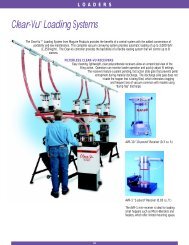
FEEDERS<br />
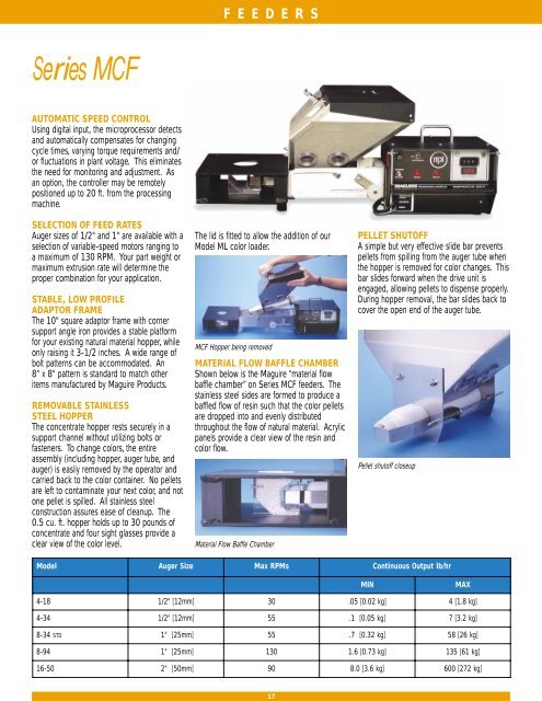
Series MCF<br />
AUTOMATIC SPEED CONTROL<br />
Using digital input, the microprocessor detects<br />
and automatically compensates for changing<br />
cycle times, varying torque requirements and/<br />
or fluctuations in plant voltage. This eliminates<br />
the need for monitoring and adjustment. As<br />
an option, the controller may be remotely<br />
positioned up to 20 ft. from the processing<br />
machine.<br />
SELECTION OF FEED RATES<br />
Auger sizes of 1/2" and 1" are available with a<br />
selection of variable-speed motors ranging to<br />
a maximum of 130 RPM. Your part weight or<br />
maximum extrusion rate will determine the<br />
proper combination for your application.<br />
STABLE, LOW PROFILE<br />
ADAPTOR FRAME<br />
The 10" square adaptor frame with corner<br />
support angle iron provides a stable platform<br />
for your existing natural material hopper, while<br />
only raising it 3-1/2 inches. A wide range of<br />
bolt patterns can be accommodated. An<br />
8" x 8" pattern is standard to match other<br />
items manufactured by <strong>Maguire</strong> <strong>Products</strong>.<br />
REMOVABLE STAINLESS<br />
STEEL HOPPER<br />
The concentrate hopper rests securely in a<br />
support channel without utilizing bolts or<br />
fasteners. To change colors, the entire<br />
assembly (including hopper, auger tube, and<br />
auger) is easily removed by the operator and<br />
carried back to the color container. No pellets<br />
are left to contaminate your next color, and not<br />
one pellet is spilled. All stainless steel<br />
construction assures ease of cleanup. The<br />
0.5 cu. ft. hopper holds up to 30 pounds of<br />
concentrate and four sight glasses provide a<br />
clear view of the color level.<br />
The lid is fitted to allow the addition of our<br />
Model ML color loader.<br />
MCF Hopper being removed<br />
MATERIAL FLOW BAFFLE CHAMBER<br />
Shown below is the <strong>Maguire</strong> “material flow<br />
baffle chamber” on Series MCF feeders. The<br />
stainless steel sides are formed to produce a<br />
baffled flow of resin such that the color pellets<br />
are dropped into and evenly distributed<br />
throughout the flow of natural material. Acrylic<br />
panels provide a clear view of the resin and<br />
color flow.<br />
Material Flow Baffle Chamber<br />
PELLET SHUTOFF<br />
A simple but very effective slide bar prevents<br />
pellets from spilling from the auger tube when<br />
the hopper is removed for color changes. This<br />
bar slides forward when the drive unit is<br />
engaged, allowing pellets to dispense properly.<br />
During hopper removal, the bar slides back to<br />
cover the open end of the auger tube.<br />
Pellet shutoff closeup<br />
Model<br />
Auger<br />
Size<br />
Max<br />
RPMs<br />
Continuous Output lb/hr<br />
MIN<br />
MAX<br />
4 -18<br />
1/2"<br />
[12mm]<br />
30<br />
. 05 [0.02 kg]<br />
4 [1.8 kg]<br />
4 -34<br />
1/2"<br />
[12mm]<br />
55<br />
. 1 [0.05 kg]<br />
7 [3.2 kg]<br />
8-34<br />
TD<br />
S " [25mm]<br />
1 55<br />
. 7 [0.32 kg]<br />
58 [26 kg]<br />
8 -94<br />
1"<br />
[25mm]<br />
130<br />
1 .6 [0.73 kg]<br />
135 [61 kg]<br />
16-50<br />
2"<br />
[50mm]<br />
90<br />
8 .0 [3.6 kg]<br />
600 [272 kg]<br />
17
FEEDERS<br />
How <strong>Maguire</strong> <strong>Feeder</strong>s Work<br />
The controller signal cord is plugged into an<br />
outlet that is energized only when the process<br />
machine screw runs. During each screw return<br />
cycle (or continuous for extrusion), the motor<br />
runs and color is metered into the throat of the<br />
process machine.<br />
The digital counter located on the face of the<br />
controller provides the means for determining<br />
the exact degree of auger rotation and,<br />
therefore, the precise amount of color that will<br />
be added. For injection molders the motor will<br />
shut off when the preset count is reached<br />
during each cycle. For extruders, an optional<br />
digital tachometer feedback is available to<br />
ensure that motor speed is precisely regulated<br />
regardless of changing torque requirements or<br />
variations in plant voltage.<br />
To determine the proper setting for the counter,<br />
a simple formula is used based on percentage<br />
of color required, a predetermined metering<br />
rate, and total shot weight in grams (or pounds<br />
per hour for extrusion applications).<br />
The controller contains a 1/27 HP DC<br />
Permanent Magnet motor with variable speed<br />
control. In the standard configuration, the<br />
motor is close coupled to a heavy duty<br />
gearbox. As the motor turns, a “hall effect”<br />
pickup device on the motor sends 3 pulses<br />
per revolution to the microprocessor controlling<br />
it. The gearbox ratio of 53:1 provides 159<br />
pulses (3 x 53) for each revolution of the<br />
motor output shaft.<br />
The thumbwheel switch on the controller<br />
should be set to the exact number of pulses<br />
that the motor is going to run before stopping.<br />
The microprocessor in the controller automatically<br />
multiplies the setting by a factor of 10.<br />
A setting of 16 on the counter will allow the<br />
controller to receive 160 pulses or run<br />
approximately one revolution before stopping<br />
(regardless of how fast or slow the motor<br />
runs).<br />
Series MLG<br />
‘LITTLE GUY’ CONCENTRATE<br />
FEEDERS<br />
These <strong>Maguire</strong> feeders are designed expressly<br />
for installation on small injection molding<br />
machines. The motor is positioned on one<br />
side and the hopper on the other to evenly<br />
balance the weight of the feeder over the feed<br />
throat of the machine.<br />
REMOTE CONTROLS<br />
A remote control configuration further reduces<br />
the weight of the equipment that is bolted to<br />
the throat.<br />
REMOVABLE HOPPER<br />
Similar to the MCF feeder, the “Little Guy”<br />
hopper, auger, and auger tube make up a<br />
complete assembly, easily removed without<br />
tools for ease of color change. Not a single<br />
pellet is left behind to contaminate your next<br />
color.<br />
SEE-THROUGH BAFFLE CHAMBER<br />
Stainless steel is used for all color contact<br />
surfaces including the hopper and flow<br />
chamber baffles. Removable acrylic windows<br />
on the flow baffle chamber permit a clear view<br />
of the resin and color flow and allow easy<br />
access to the chamber.<br />
Model<br />
Auger<br />
Size<br />
Max<br />
RPMs<br />
Continuous Output lb/hr<br />
MIN<br />
MAX<br />
M LG-4-18<br />
1/2"<br />
[12mm]<br />
30<br />
. 05 [0.02 kg]<br />
4 [1.8 kg]<br />
M LG-4-34<br />
1/2"<br />
[12mm]<br />
55<br />
. 1 [0.05 kg]<br />
7 [3.2 kg]<br />
18
FEEDERS<br />
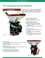
Series MPF Powder <strong>Feeder</strong>s<br />
The MPF powder feeder is designed to handle powders<br />
that do NOT flow well. The hopper features an integral<br />
bridge breaker bar that sweeps the bottom of the<br />
hopper once every 2 turns of the auger. This bridge<br />
breaker serves to keep the flights of the auger full and<br />
assures accurate metering. The hopper capacity is<br />
restricted to about 1/2 cu. ft. (about 10 pounds).<br />
Keeping the capacity low avoids compaction and helps<br />
with metering. The hopper is stainless steel and<br />
removable for easy cleanout. The bridge breaker bar is<br />
belt driven by the auger feeder motor.<br />
Model<br />
Auger<br />
Size<br />
Max<br />
RPMs<br />
Continuous Output lb/hr<br />
MIN<br />
MAX<br />
M PF-4-18<br />
1/2"<br />
[25mm]<br />
30<br />
0 .04 [18 gm]<br />
2.9 [300 gm]<br />
M PF-8-34<br />
1"<br />
[25mm]<br />
55<br />
. 3 [14 kg]<br />
23 [10.4 kg]<br />
Series MRF Regrind <strong>Feeder</strong>s<br />
CONTROL REGRIND USAGE<br />
Installed beneath existing natural material<br />
hoppers, these special feeders provide the<br />
means to easily and accurately use previously<br />
colored regrind while avoiding double-coloring.<br />
Regrind enters the flow of resin at the same<br />
height as the color feed. Baffles ensure even<br />
distribution and mix of materials.<br />
MPF, MPA, MDA) which<br />
automatically compensate<br />
for the percent of regrind<br />
set for the mix. When<br />
regrind runs low, the regrind<br />
feeder will automatically shut<br />
off and full 100% coloring will be<br />
resumed.<br />
SELECT % REGRIND DIRECTLY AND<br />
AVOID “DOUBLE” COLORING<br />
A “% regrind” rotary switch is provided on the<br />
feeder controller for selecting the exact<br />
percentage of regrind to be added. Signal<br />
output from the regrind feeder is accepted by<br />
all <strong>Maguire</strong> standard feeders (Series MCF,<br />
CLEAN OUT CHUTE<br />
Complete emptying of the<br />
hopper is done rapidly and<br />
easily by way of a hinged<br />
cleanout chute located<br />
directly under the feed<br />
screw and hopper.<br />
Model<br />
Auger<br />
Size<br />
Max<br />
RPMs<br />
Continuous<br />
Output lb/hr<br />
Dispense<br />
MIN<br />
M AX<br />
(One Cycle)<br />
M RF-8-34<br />
1"<br />
[25mm]<br />
55<br />
1 .8 [82 gm]<br />
58<br />
[26.4 kg]<br />
.05 cc<br />
M RF-8-50<br />
1"<br />
[25mm]<br />
100<br />
2 .7 [1.2kg]<br />
105<br />
[47.7 kg]<br />
.08 cc<br />
M RF-16-50<br />
2"<br />
[50mm]<br />
100<br />
5 .3 [2.4 kg]<br />
533<br />
[242.3 kg]<br />
.4 cc<br />
M RF-16-94<br />
2"<br />
[50mm]<br />
188<br />
10<br />
[4.5 kg]<br />
1000<br />
[445.5 kg]<br />
.8 cc<br />
M RF-16-160<br />
2"<br />
[50mm]<br />
320<br />
17<br />
[7.7 kg]<br />
1700<br />
[772.7 kg]<br />
1.3 cc<br />
19
FEEDERS<br />
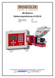
Series MSF Starve <strong>Feeder</strong>s<br />
The Model MSF starve feeder carefully<br />
regulates the volume of natural material<br />
supplied to the feed throat of the process<br />
machine. The Model MSF starve feeder,<br />
weighing less than 50 pounds, is compact<br />
and easy to install. It is mounted between the<br />
existing hopper and the feed throat of the<br />
machine adding only 8 inches to the height<br />
of your hopper. Your hopper remains directly<br />
over the feed throat of your machine and<br />
is not off-set as is the case with some<br />
competitors’ units.<br />
IMPROVES CONTROL OF<br />
VENTED SCREW<br />
When used in conjunction with a vented screw<br />
the MSF starve feeder allows the operator to<br />
regulate the feed to the rear portion of the<br />
screw. If the front portion of the screw is<br />
unable to extrude plastic as rapidly as the rear<br />
portion, then the excess flow from the rear will<br />
be forced out the vent. This condition could<br />
result from:<br />
A. The use of back pressure during screw<br />
return time<br />
B. Worn screw flights in the forward zone<br />
C. Intentionally unbalanced temperatures<br />
over the length of the barrel, etc.<br />
Use of a starve feeder allows careful regulation<br />
of the volume of material that is metered to the<br />
rear feed section of the screw, so an operator<br />
may override the tendency for material to<br />
escape from the vent.<br />
IMPROVES MATERIAL PROCESSING<br />
As plastic pellets are heated and plasticized,<br />
surface moisture and some volatiles will be<br />
driven off as vapor and steam. The vapor and<br />
steam that travel backwards will re-condense<br />
on the colder pellets in the feed zone and<br />
hopper, and then will be carried into the screw<br />
over and over again. “Starve feeding” does<br />
two things to help remedy this problem. First,<br />
a “starved” screw will have a continuous air<br />
passage directly behind the spiraling screw<br />
flight that will allow vapors to easily escape<br />
back through to the feed throat. Second, the<br />
starve feeder itself provides a vent to atmosphere<br />
so that vapors need not travel up<br />
through the cold resin in the hopper.<br />
REDUCE DRIVE MOTOR TORQUE<br />
Some granular forms of resin feed so<br />
efficiently at the feed section of the screw that<br />
the horsepower or torque available to drive the<br />
screw is not sufficient, and the drive motor<br />
becomes overloaded. Starve feeding will<br />
correct this problem by metering resin at a rate<br />
that does not exceed the horsepower or<br />
torque of the drive motor.<br />
CONTROL SLIPPAGE<br />
When the feed zone of a process machine is<br />
NOT cooled, the plastic pellets in the throat<br />
may preheat considerably if throughput rate is<br />
low and residence time in the throat is too<br />
long. This may cause premature melting in the<br />
barrel, resulting in screw slippage that will<br />
produce erratic and extended screw return<br />
times. Starve feeding eliminates residence<br />
time and consequently prevents screw<br />
slippage. In these situations, starve feeding<br />
actually can produce a shorter screw return<br />
time than with “flood” feeding.<br />
NO CALIBRATION REQUIRED<br />
Your operator need only select the “percent”<br />
of full flow desired; such as 70% or 80%.<br />
The microprocessor will self-calibrate by first<br />
matching the extrusion rate and then automatically<br />
cutting back to the selected reduced<br />
“starve” rate of feed. No calibration of the<br />
system is ever necessary.<br />
MANUAL BYPASS<br />
A hinged flow plate allows conventional flood<br />
feed for manually bypassing the “starve”<br />
system.<br />
MSF Assembly<br />
20
VOLUMETRIC<br />
CONTROLS<br />
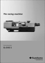
<strong>Maguire</strong> Volumetric Controls<br />
Employees have little time to monitor volumetric feeders<br />
Automatic Speed Control<br />
<strong>Maguire</strong> <strong>Products</strong> offered its first microprocessor-based automatic<br />
speed controller in 1981. More than 15,000 feeders have been<br />
sold and are operating today!<br />
Automatic Speed control eliminates the need to manually adjust<br />
motor speed to properly control the rate of color or additive<br />
delivery. With automatic speed control, the operator sets only a<br />
digital counter for the exact amount of color that is to be added<br />
during each molding cycle.<br />
For Injection Molders the microprocessor inside the controller<br />
measures the screw return time of each cycle. A proper motor<br />
speed is then calculated for the next cycle so that the exact amount<br />
of color requested by the counter setting is dispensed over the full<br />
time available. As screw return times change over hours of<br />
production, motor speed and metering rate adjust automatically.<br />
For Extruders running in “continuous” mode, the counter setting<br />
will directly regulate motor speed. A digital tach feedback from the<br />
motor armature assures that motor speed is precisely held. Uniform dispensing and consistent<br />
coloring are assured: overcoloring is eliminated.<br />
Calibration<br />
It is only necessary to calibrate a given material one time. Once the machine is calibrated for a<br />
particular grade of material and the proper setting is calculated, the metering rate for that<br />
material is determined. For future reference the user should make note of the setting and use it<br />
when that material is run again. It is not necessary to recalibrate.<br />
The actual production environment is not at all like a lab. Your employees<br />
have better things to do than constantly monitor your color feeders.<br />
With many competitors’ units you adjust color by adjusting motor<br />
speed. The only way to set the quantity of color that is going to be<br />
metered is to set the speed of the motor, and know how long it is going<br />
to run (screw return time). The speed of the motor will vary with the<br />
plant voltage, which will change throughout the day, generally increasing<br />
in the evening. The screw return time will change as temperature<br />
changes, with variations in the resin, and with adjustments to back<br />
pressure.<br />
The only way to know how much color is being added per cycle is to<br />
actually take a sample and weigh it. You can be sure that if this were<br />
done every hour, an adjustment would be required every time.<br />
In actual practice, few processors calibrate equipment on a frequent<br />
basis. The workload on individuals in the factory is such that they do<br />
only those things necessary to make quality parts. Conservation of<br />
color is secondary. Putting in too little color will produce a rejected part,<br />
but an error on the plus side will not cause a noticeable problem. This<br />
error does, however, cost a lot of money.<br />
Automatic speed control completely eliminates the need for motor<br />
speed adjustment.<br />
21
VOLUMETRIC<br />
CONTROLS<br />
No “double” coloring of regrind<br />
All automatic speed control units are preprogrammed<br />
to accept signals from our<br />
regrind feeders. Should you purchase our<br />
MRF Regrind <strong>Feeder</strong> to meter regrind at-thethroat,<br />
our Color Controllers will automatically<br />
reduce metering to prevent over-coloring the<br />
regrind. Since color controllers are normally<br />
set to color 100% natural material, the<br />
occasional introduction of regrind is usually<br />
done without thought to the cost of coloring it<br />
twice. Should you wish to address this<br />
problem in the future, our automatic speed<br />
control units are already equipped to interact<br />
with our Regrind <strong>Feeder</strong>s.<br />
Extrusion Following Option<br />
With this option, a controller “follows” the<br />
speed of the extruder automatically. Any<br />
changes in extruder speed are sensed and<br />
followed exactly by the Controller output.<br />
A tachometer that currently exists on your<br />
extruder provides either an AC or DC voltage<br />
output that varies with extruder RPM. This<br />
signal is fed into the <strong>Maguire</strong> extruder-voltage<br />
preprocessor. This signal is passed onto the<br />
main processor through an optical coupler.<br />
A calibration pot allows each preprocessor to<br />
be exactly tuned for your particular extruder.<br />
Calibration is required only once. For correct<br />
operation, you simply need to set the digital<br />
counter for the proper controller metering rate<br />
at full extruder speed. Anything less than full<br />
speed will automatically be reflected in a<br />
corresponding reduced metering rate.<br />
Voltages from 1 to 500 can be tracked.<br />
Accuracy is held over the full range.<br />
Direct-Entry Controller<br />
The Direct-Entry Controller is a contoller upgrade that greatly simplifies the operation<br />
of volumetric feeders for pellet, powder, or liquid additives. The unit, available as an<br />
option, eliminates the need for calculation and monitoring by the operator. Once the<br />
operator has set the desired colorant or additive level by using a simple thumbwheel,<br />
the controller automatically calculates the metering rate, compensates for color<br />
already present in regrind, and adjusts to variations in the molding or extrusion<br />
process.<br />
Expanded electronic recording functions are also provided. Hard-copy output can be<br />
generated directly through a printer port that is standard in the controller. Processors<br />
can document work-orders, operator number, machine numbers, set-up parameters,<br />
and other data. To enhance inventory management the unit has the ability to<br />
document running totals of natural, regrind, color, and additive.<br />
Cycle, continuous, and extrusion following modes are available on all models.<br />
22
FEEDER ACCESSORIES<br />
/ PARTS<br />
SPACER FRAMES<br />
Model 844 3 1/2” high spacer frame<br />
Model 845 8 1/4” high spacer frame<br />
Model 844-6 Transition to 6” x 6” plate<br />
Model 844-7 Transition to 4”x 4” plate<br />
Model 844-12 Transition to 12” x 12” plate<br />
Model 844-14 Transition to 14” x 14” plate<br />
<strong>Maguire</strong> spacer frames allow you to easily raise your <strong>Maguire</strong><br />
feeder above the feed throat of your process machine if<br />
clearance is a problem. The spacer frame mounts directly below<br />
the standard feeder adaptor frame, adding height to your feeder<br />
assembly.<br />
Constructed of 1/4" thick 10"x10" steel plates, and four sturdy<br />
angle steel corner supports, these frames provide a stable<br />
platform for carrying heavy hopper loads.<br />
EXTENDED HOPPER<br />
The addition of this extension to our standard feeder hopper<br />
will increase capacity from about 22 pounds (10 kg) to 62<br />
pounds (28 kg). This extra capacity reduces the frequency of<br />
refills whether hand-filling or loading automatically.<br />
Keep in mind that this extension may interfere with your main<br />
natural material hopper. It will also add some weight to the<br />
hopper when you wish to remove it for color changes.<br />
The side extensions are aluminum and pre-punched for easy<br />
assembly and attachment to any existing hopper. You may add<br />
this option yourself at any time should you decide later that you<br />
need the extra capacity.<br />
AUGERS<br />
ACA4<br />
ACA8<br />
ACA8p<br />
ACA16<br />
1/2” auger with coupling<br />
1” auger with coupling<br />
1” powder (spring type) auger with coupling<br />
2” auger with coupling<br />
AUGER TUBES<br />
1808-4 1/2” auger tube<br />
1808-8 1” auger tube<br />
1808-8P 1” powder auger tube<br />
1808-16 2” auger tube<br />
SPARE CONTROLLER<br />
ACA Spare automatic speed controller<br />
ACA-E Spare automatic speed controller<br />
w/ Extrusion Following<br />
SPARE DIRECT ENTRY CONTROLLER<br />
ACA-D Spare direct entry controller<br />
23
FEEDER ACCESSORIES<br />
/ PARTS<br />
LOW LEVEL ALARM SYSTEM<br />
Reduce monitoring requirements by floor personnel with the<br />
Series LLA alarm systems used to signal HIGH or LOW<br />
material-supply conditions. The easy-to-install solid-state<br />
sensor can detect pelletized, liquid, or powder material. A<br />
bright amber strobe light and an electronic beeper alert the<br />
user to an ALARM condition. A duplex outlet is provided to<br />
control a loading system. Power to this outlet is switched off<br />
when the sensor is covered. Single-station and multi-station<br />
(up to six) models are available.<br />
SWIVEL PLATES<br />
ASW3 Swivel Plate with 3 1/2” high spacer frame<br />
ASW8 Swivel Plate with 8 1/4” high spacer frame<br />
<strong>Maguire</strong> swivel plates allow for easy repositioning of your<br />
<strong>Maguire</strong> auger feeder. The swivel plate mounts directly under<br />
the auger feeder adaptor frame assembly and allows for full<br />
rotation of the feeder to any position you desire. Tightening the<br />
four hold-down clamps will prevent movement if you wish to<br />
maintain one fixed position.<br />
JUG STYLE HOPPER<br />
This optional low hopper allows color to be dispensed directly<br />
from 5-gallon jugs into the color feed auger. With this system,<br />
5-gallon containers are pre-filled with color or additive. This<br />
makes it easy to keep a variety of color pellets or additives<br />
within reach of each press for rapid changes.<br />
MCF HOPPER/AUGER ASSEMBLY MLG HOPPER/AUGER ASSEMBLY MPF HOPPER/AUGER ASSEMBLY<br />
24