C60/C67 HPW - Gemu
C60/C67 HPW - Gemu
C60/C67 HPW - Gemu

You also want an ePaper? Increase the reach of your titles
YUMPU automatically turns print PDFs into web optimized ePapers that Google loves.
CleanStar ® 3/5 Way<br />
PFA Diaphragm Valves<br />
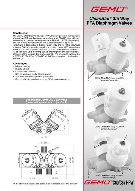
Construction<br />
The GEMÜ CleanStar ® <strong>C60</strong> / <strong>C67</strong> <strong>HPW</strong> ultra pure pneumatically or manually<br />
operated 3/5 way diaphragm valves have a full PFA-HP body with two<br />
valve seats. All medium wetted parts are in PFA-HP or PTFE (diaphragm).<br />
The non-wetted bonnet is PVDF. The standard version of type <strong>C60</strong><br />
(pneumatic) is designed as a diverter valve: 1 x NC and 1 x NO (2 pneumatic<br />
actuators <strong>C60</strong>, one normally closed, one normally open). <strong>C60</strong> has a stroke<br />
limiter and an optical position indicator (1), <strong>C67</strong> (manual) has a travel stop<br />
(6) as standard. Solid mounting lugs (2) are integrated and there is also a<br />
connection for a leakage detection sensor (3). The union nuts can be either<br />
in PVDF-HP, PFA-HP or C-PFA-HP (4). <strong>C67</strong> has a standard optical position<br />
indicator (5).<br />
1<br />
Advantages<br />
• Minimal deadleg<br />
• High K v values<br />
• Optional flow direction<br />
• Can be used as a media blending valve<br />
• Actuators can be independently controlled<br />
• Can be fully integrated with existing GEMÜ process controls<br />
4<br />
3<br />
GEMÜ CleanStar ® 3 way valve <strong>C60</strong><br />
(pneumatic/pneumatic)<br />
2<br />
Dimensions GEMÜ <strong>C60</strong> 3 way valve<br />
(pneumatic/pneumatic) [mm/inch]<br />
6<br />
GEMÜ CleanStar ® 3 way valve <strong>C60</strong><br />
(pneumatic/manual)<br />
1<br />
5<br />
All the above dimensions are identical for connection sizes 1/2” and 3/4”.<br />
4<br />
3<br />
GEMÜ CleanStar ® 3 way valve <strong>C67</strong><br />
(manual/manual)<br />
2<br />
<strong>C60</strong>/<strong>C67</strong> <strong>HPW</strong>
Range Overview CleanStar ® <strong>C60</strong>/<strong>C67</strong> 3 way valves<br />
X<br />
Flare<br />
connection<br />
Y<br />
Z<br />
X<br />
Butt-weld<br />
spigots<br />
Y<br />
Type of connection / Availability<br />
Z<br />
X<br />
Space saver<br />
Pos. X + Z Pos. Y Pos. X + Z + Y<br />
Y<br />
Z<br />
Size<br />
Connection<br />
Code<br />
international<br />
1/2“ - 1/2“ - 1/2“ 8 10<br />
3/4“ - 3/4“ - 3/4“ 12 15<br />
on request<br />
on request<br />
X<br />
Y<br />
on request<br />
Z<br />
X<br />
Y<br />
on request<br />
Z<br />
DN<br />
Actuator size<br />
Code<br />
2<br />
Technical Data<br />
Flow medium<br />
Suitable for any inert or corrosive gases or liquids,-especially<br />
high purity media- which do not corrode the respective<br />
body and diaphragm materials.<br />
Flow direction<br />
Optional<br />
Operating pressure<br />
Max. 6 bar when applied upstream only<br />
Vacuum<br />
400 mbar/abs*<br />
* The life expectancy of the valve may be affected if exposed to a<br />
greater vacuum.<br />
Ambient temperature<br />
Max. 60°C (130°F)<br />
Materials<br />
Medium wetted parts (body)<br />
Diaphragm<br />
Bonnet parts, non-wetted<br />
Control pressure (only <strong>C60</strong>)<br />
“Normally closed” (c.f. 1)<br />
“Normally open” (c.f. 2)<br />
and “double acting” (c.f. 3)<br />
PFA<br />
PTFE<br />
PVDF<br />
4-7 bar<br />
max. 4 bar<br />
Operating temperature<br />
See temperature/pressure diagram on page 4<br />
Control air connection (only <strong>C60</strong>)<br />
Size G 1/8<br />
K V / C V values<br />
Connection Size K v -Wert C v -Wert<br />
Size Connection Code<br />
Code<br />
international<br />
DN Actuator l/min US gal/min<br />
1/2” tube Flare connection 75 and 77 8 10 2 28 2.0<br />
3/4” tube Flare connection 75 and 77 12 15 2 53 3.7<br />
Control Air Volume - <strong>C60</strong><br />
Actuator size Control function Actuator Volume (cm³)<br />
1 Normally closed 24.0<br />
2<br />
2 Normally open 39.0<br />
3 Double acting (closed) 39.0<br />
3 Double acting (open) 24.0<br />
<strong>C60</strong>/<strong>C67</strong> <strong>HPW</strong><br />
2
Order data<br />
Position of space saver (optional)<br />
Space saver in X-position<br />
Y<br />
Code<br />
X<br />
Nominal size (Connection Y)<br />
Code<br />
1/2“ tube DN 10 8<br />
3/4“ tube DN 15 12<br />
Space saver in Y-position<br />
Space saver in Z-position<br />
X<br />
X<br />
Y<br />
Y<br />
Z<br />
Z<br />
Y<br />
Z<br />
Body geometry<br />
V body<br />
Connection type (Connection Y)<br />
Code<br />
Code<br />
Flare connection with C-PVA union nut 73<br />
(also for space saver)<br />
Flare connection with PVDF union nut 75<br />
(also for space saver)<br />
Flare connection with PFA union nut 77<br />
(also for space saver)<br />
V<br />
Space saver in X+Z-position<br />
X<br />
Y<br />
Z<br />
S<br />
Body material<br />
Code<br />
PFA 30<br />
Diaphragm material<br />
Code<br />
X<br />
Z<br />
PTFE<br />
5A<br />
Control function / Actuator type (code)<br />
Valve 1 (X - Y) Valve 2 (Z - Y)<br />
Type<br />
Actuator type<br />
Control<br />
function<br />
Type<br />
Actuator type<br />
Control<br />
function<br />
Code<br />
<strong>C60</strong> Normally closed 1 <strong>C60</strong> Normally closed 1 1<br />
<strong>C60</strong> Normally closed 1 <strong>C60</strong> Normally open 2 D<br />
<strong>C60</strong> Normally closed 1 <strong>C67</strong> Manually operated 0 F<br />
<strong>C67</strong> Manually operated 0 <strong>C60</strong> Normally closed 1 A<br />
<strong>C67</strong> Manually operated 0 <strong>C67</strong> Manually operated 0 0<br />
Further combinations on request.<br />
Actuator size<br />
Code<br />
Actuator 2 2<br />
Nominal size (connections X + Z) Code<br />
1/2“ tube DN 10 8<br />
3/4“ tube DN 15 12<br />
Connection type (connections X+ Z)<br />
Code<br />
Flare connection with C-PVA union nut 73<br />
(also for space saver)<br />
Flare connection with PVDF union nut 75<br />
(also for space saver)<br />
Flare connection with PFA union nut 77<br />
(also for space saver)<br />
Order example <strong>C60</strong> Y 8 V 75 30 5A F 2 S 8 75 <strong>HPW</strong><br />
Type<br />
<strong>C60</strong><br />
Position of space saver (optional) Y<br />
Nominal size (code) 8<br />
Body geometry (code)<br />
V<br />
Connection (code) 75<br />
Body material (code) 30<br />
Diaphragm material (code)<br />
5A<br />
Control function / actuator type (code)<br />
F<br />
Actuator size (code) 2<br />
Position of space saver (optional)<br />
S<br />
Nominal size of connections X and Z (code)* 8<br />
Connection type of connections X and Z (code)* 75<br />
High Purity, white<br />
<strong>HPW</strong><br />
* Connections are limited to versions with same nominal sizes at all positions. Size variations to follow.<br />
3<br />
<strong>C60</strong>/<strong>C67</strong> <strong>HPW</strong>
Temperature / pressure - diagram<br />
Temperature (°F)<br />
-4 14 32 50 68 86 104 122 140 158 176 194 212 230 248 266 284 302<br />
7<br />
105<br />
6<br />
90<br />
Pressure (bar)<br />
5<br />
4<br />
3<br />
Engineered<br />
working range<br />
75<br />
60<br />
45<br />
Pressure (PSI)<br />
2<br />
30<br />
1<br />
15<br />
-20 -10 0 10 20 30 40 50 60 70 80 90 100 110 120 130 140 150<br />
Temperature (°C)<br />
Information on the use of the temperature / pressure diagram<br />
The temperature / pressure diagram is only an orientation aid. The data refer to water as a working medium.<br />
A change of operating conditions or other media may result in deviations. In case of doubt it is advisable to test the behavior of the material<br />
under the definitive operating conditions by means of a test installation.<br />
Dimensions / Tolerances<br />
Overlap dimensions and thread sizes of flare connections<br />
Tolerances<br />
Thread sizes of Flare connections<br />
Tube size Thread designation Standard<br />
1/2“ 3/4“-20-UNEF ANSI B 1.1<br />
3/4“ 1“-20-UNEF ANSI B 1.1<br />
• The CleanStar ® plastic parts are manufactured to DIN 16901-140.<br />
• In Space Saver - Flare connections tolerances of ±2.5mm are possible.<br />
• Tolerance data for butt weld connections will vary depending on the design of the welding machine used.<br />
4<br />
<strong>C60</strong>/<strong>C67</strong> <strong>HPW</strong>
Dimensions - GEMÜ <strong>C60</strong> 3 way valves (pneumatic/manual)<br />
[mm/inch]<br />
All dimensions stated in all actuator drawings are identical for connection sizes 1/2” and 3/4”.<br />
Dimensions - GEMÜ <strong>C67</strong> 3 way valves (manual/manual)<br />
[mm/inch]<br />
<strong>C60</strong>/<strong>C67</strong> <strong>HPW</strong><br />
5
Accessories<br />
GEMÜ <strong>C67</strong> STA<br />
Service tool for actuators<br />
GEMÜ 1098<br />
Flaring mandrel<br />
GEMÜ CF STF<br />
Service tool for<br />
flare union nuts<br />
GEMÜ <strong>C67</strong> LOD<br />
Lock out device<br />
Technical Datasheet<br />
Further High Purity products<br />
HydraLine ®<br />
Pressure Measurement Systems<br />
PurePlus ®<br />
High Purity PVDF/PP Valves and Flowmeters<br />
SonicLine ®<br />
Ultra Sonic Flowmeter<br />
HydraLine ®<br />
Pressure Measurement<br />
Systems<br />
FlareStar®<br />
Ultra pure PFA tube and weld fittings<br />
PurePlus ®<br />
High Purity PVDF/PP<br />
Valves and Flowmeters<br />
TubeStar®<br />
High Purity PFA Tubing<br />
SonicLine ®<br />
Ultra-Sonic<br />
Flowmeters<br />
Should there be any doubts or misunderstandings, the German<br />
version of this data sheet is the authoritative document!<br />
FlareStar ®<br />
Ultra Pure PFA<br />
Tube and Weld Fittings<br />
TubeStar ®<br />
High Purity PFA Tubing<br />
Subject to modification · 09/2008 · 88224035<br />
VALVES, MEASUREMENT<br />
AND CONTROL SYSTEMS<br />
GEMÜ Gebr. Müller · Apparatebau GmbH & Co. KG · Fritz-Müller-Str. 6-8 · D-74653 Ingelfingen-Criesbach · Tel. +49 (0) 7940/123-0 · Telefax +49 (0) 7940/123-224<br />
e-mail: info@gemue.de · http://www.gemue.de