Toll Facilities Model Cube Voyager Version, FDOT - FSUTMSOnline
Toll Facilities Model Cube Voyager Version, FDOT - FSUTMSOnline
Toll Facilities Model Cube Voyager Version, FDOT - FSUTMSOnline

Create successful ePaper yourself
Turn your PDF publications into a flip-book with our unique Google optimized e-Paper software.
<strong>Toll</strong> <strong>Facilities</strong> <strong>Model</strong><br />
<strong>Cube</strong> <strong>Voyager</strong> <strong>Version</strong><br />
June 1, 2009<br />
Prepared For:<br />
Florida Department of Transportation<br />
Prepared By:<br />
Fennessy Associates<br />
Wilbur Smith Associates<br />
BCC Engineering, Inc.
<strong>Toll</strong> <strong>Facilities</strong> <strong>Model</strong>: <strong>Cube</strong> <strong>Voyager</strong> <strong>Version</strong><br />
I. Introduction<br />
The <strong>Toll</strong> <strong>Facilities</strong> <strong>Model</strong> (FM) was first developed for the Florida Department of<br />
Transportation in order to better simulate the delay caused by the normal operation of<br />
toll plazas. Using a special set of calculations, the <strong>Toll</strong> FM divided the delay at a toll<br />
plaza into three general components: deceleration, queuing, and acceleration. The <strong>Toll</strong><br />
FM was first implemented in the FORTRAN language and included as part of the<br />
FSUTMS TRANPLAN highway assignment program known as EQUILIBRIUM<br />
HIGHWAY LOAD. With the adoption of <strong>Cube</strong> <strong>Voyager</strong> as the standard modeling<br />
software platform for the State of Florida it became necessary to begin a series of<br />
conversions of preexisting FSUTMS standards and methodologies from their older<br />
TRANPLAN formats into the newer <strong>Cube</strong> <strong>Voyager</strong> formats. The <strong>Toll</strong> FM methodology<br />
was converted into <strong>Cube</strong> <strong>Voyager</strong> for the benefit of the modeling community so that<br />
accurate and reliable forecasts on toll facilities could continue to be performed. More<br />
information on the original <strong>Toll</strong> FM as it was implemented in TRANPLAN can be found<br />
in FSUTMS Technical Report No. 5: FSUTMS Highway Network Pathbuilding <strong>Model</strong><br />
(HPATH) prepared by the Florida Department of Transportation Central Office, Systems<br />
Planning in 1997. This report can be found in electronic format as part of a series of<br />
documentation on FSUTMS and TRANPLAN commonly known as the FSUTMS User’s<br />
Library CD.<br />
The conversion of the <strong>Toll</strong> FM into <strong>Cube</strong> <strong>Voyager</strong> attempts to maintain methodological<br />
fidelity with the original application used in TRANPLAN. As a result, the new <strong>Toll</strong> FM<br />
represents a literal translation of its predecessor into the new format. All calculations<br />
and data requirements remain consistent with the original <strong>Toll</strong> FM.<br />
This document details the final product of the conversion of the <strong>Toll</strong> FM into <strong>Cube</strong><br />
<strong>Voyager</strong>. It is separated into four sections. The first section is this introduction. It is<br />
meant to familiarize the reader with a brief history of the <strong>Toll</strong> FM and the purpose for<br />
this conversion. The second section discusses the data needs of the <strong>Toll</strong> FM along with<br />
necessary modifications to the highway network for proper <strong>Toll</strong> FM execution. The third<br />
section presents the methodology of the <strong>Toll</strong> FM along with associated samples of<br />
scripting that demonstrate implementation methodology in a <strong>Cube</strong> <strong>Voyager</strong> context.<br />
The fourth section is a brief conclusion.<br />
The <strong>Toll</strong> FM has been designed for use within any standard user equilibrium highway<br />
assignment model in the State of Florida. Certain regional differences contained within<br />
the various models in Florida may require slight adjustments be made to the <strong>Toll</strong> FM<br />
script in order to ensure proper implementation. It is the responsibility of the agency<br />
implementing the <strong>Toll</strong> FM to possess a thorough understanding of their model and <strong>Toll</strong><br />
FM sufficient enough to ensure proper <strong>Toll</strong> FM implementation for that agency’s<br />
respective area. For more information concerning the <strong>Toll</strong> FM, please contact Mr.<br />
1
<strong>Toll</strong> <strong>Facilities</strong> <strong>Model</strong>: <strong>Cube</strong> <strong>Voyager</strong> <strong>Version</strong><br />
Vladimir Majano at the Florida Department of Transportation, Central Office, Systems<br />
Planning Office at Vladimir.Majano@dot.state.fl.us.<br />
2
<strong>Toll</strong> <strong>Facilities</strong> <strong>Model</strong>: <strong>Cube</strong> <strong>Voyager</strong> <strong>Version</strong><br />
II. <strong>Model</strong> Modifications<br />
All models use specific sets of attributes to facilitate the calculations required for travel<br />
demand forecasting. Typically, each element in a model requires particular attributes to<br />
function properly. For example, FSUTMS uses a combination of roadway facility types,<br />
land use area types, and the number of lanes for a given segment to derive the speeds<br />
and capacities needed to calculate travel times and highway congestion. Likewise, the<br />
<strong>Toll</strong> FM requires specific sets of attributes for proper execution. Also, the <strong>Toll</strong> FM<br />
requires that toll plaza links be coded in a particular manner. These issues are<br />
discussed below.<br />
Catalog Keys<br />
<strong>Cube</strong> <strong>Voyager</strong> makes use of certain variables that can be called in any script at any<br />
time in the model. These particular variables, known as catalog keys, can be created<br />
and defined by model developers and modified by model users where appropriate.<br />
Catalog keys allow modelers to predefine certain values that will be used throughout the<br />
model without requiring the modeler to adjust the value individually in every script where<br />
the value occurs whenever a change is desired. For example, a modeler could decide<br />
that the highway assignment model should run up to a maximum of 50 iterations in<br />
order to ensure closure. Since highway assignment usually occurs twice in many transit<br />
models and up to five times in a Time-of-Day model, normally the modeler would need<br />
to go into each script of the model and change the value, therefore it would be more<br />
efficient to only need to change the value once. By using catalog keys, the modeler<br />
could reduce the number of times needed to make this change.<br />
The <strong>Toll</strong> FM makes use of four specific catalog keys that can be modified in <strong>Cube</strong>’s<br />
scenario manager. The first is the Coefficient of <strong>Toll</strong>, or CTOLL, that is described later<br />
in this document in the section on scripting. This catalog key is represented in the script<br />
as {CTOLL}.<br />
The second catalog key is the Coefficient of <strong>Toll</strong> Scale, or CTOLLSCALE. This key is<br />
represented in the script as {CTOLLSCALE}. The value can be set to one of three<br />
distinct values, each of which represents how the model should scale the toll. These<br />
values are:<br />
• 1 – Coefficient of <strong>Toll</strong> is in minutes per dollar<br />
• 60 – Coefficient of <strong>Toll</strong> is in hours per dollar (most common of Florida <strong>Toll</strong> FMs)<br />
• 100 – Coefficient of <strong>Toll</strong> is in minutes per cent<br />
The value of CTOLLSCALE should be determined by the implementing agency based<br />
on their understanding of local surveys and statistics.<br />
3
<strong>Toll</strong> <strong>Facilities</strong> <strong>Model</strong>: <strong>Cube</strong> <strong>Voyager</strong> <strong>Version</strong><br />
The third catalog key is the maximum volume to capacity ratio, or VCMAX. It specifies<br />
an upper limit to the allowable volume over capacity (V/C) ratio to be used in the Bureau<br />
of Public Roads (BPR) delay equation. This key is represented in the model script as<br />
{VCMAX}. In the TRANPLAN version of FSUTMS, this variable was described as<br />
“Specifies maximum BPR exponent allowed.” With a default value of 4 in TRANPLAN,<br />
the typical range of the maximum V/C is between 4 and 10 for Florida models. The<br />
major urban area models, such as the Southeast Regional Planning <strong>Model</strong> (SERPM),<br />
Tampa Bay Regional Planning <strong>Model</strong> (TBRPM), and Central Florida Regional Planning<br />
<strong>Model</strong> (CFRPM), utilize the value of four (4). The lowest VCMAX value, three (3), is<br />
used in the Treasure Coast Regional Planning <strong>Model</strong> (TCRPM). Most of the District 1,<br />
2, and 3 models utilize the value of ten (10) as their maximum allowed volume over<br />
capacity. This value should be verified and calibrated by the implementing agency<br />
based on their local traffic characteristics and uniqueness of transportation system.<br />
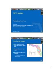
VCMAX is used in order to constrain the maximum congested travel time that can occur<br />
on an highway link. The standard BPR volume delay function expresses an exponential<br />
increase in congested travel time as the volume-over-capacity ratio increases. As the<br />
volume on a link increases, the congested travel time on that link quickly becomes<br />
tremendously long. The following chart demonstrates this relationship on an<br />
hypothetical highway link with a four minute free-flow travel time:<br />
BPR Volume Delay Function Curve: Free Flow Time at 4 Minutes<br />
6,000<br />
5,500<br />
Congested Travel Time in Minutes<br />
5,000<br />
4,500<br />
4,000<br />
3,500<br />
3,000<br />
2,500<br />
2,000<br />
1,500<br />
1,000<br />
500<br />
No VCMAX<br />
VCMAX = 4<br />
VCMAX = 6<br />
VCMAX = 8<br />
0<br />
0 1 2 3 4 5 6 7 8 9 10<br />
Volume over Capacity<br />
4
<strong>Toll</strong> <strong>Facilities</strong> <strong>Model</strong>: <strong>Cube</strong> <strong>Voyager</strong> <strong>Version</strong><br />
The fourth catalog key determines whether the <strong>Toll</strong> FM treats the model as a Single<br />
Server Queue model or a Multi Server Queue model. A Single Server Queue model<br />
assumes that all users of a toll plaza approach a single barrier. It would be as if a given<br />
toll plaza only had one lane open for the collection of tolls. For this reason, the Single<br />
Server Queue model is extremely simple to implement. The Multi Server Queue model<br />
is a more sophisticated approach that considers the availability of multiple lanes at the<br />
toll plaza and the driver’s ability to pull out of more congested lanes into less congested<br />
lanes. This type of model is more complex to implement but is meant to provide a better<br />
description of queue delays at toll plazas. The distinctions between these two queue<br />
types are also described further in the scripting section of this document. This catalog<br />
key is represented in the script as {QUEUETYPE}. The catalog key value can be set to<br />
one of two distinct values:<br />
• One (1) for Single Server Queue or<br />
• Two (2) for Multi Server Queue (default value).<br />
Highway Network Requirements<br />
<strong>Toll</strong>s impact travel demand models primarily by influencing the time it takes to travel<br />
from one point of the model to another. This influence is determined by adding the<br />
estimated time it takes to pay one’s toll to the total travel time and by converting the<br />
price of the toll into a time equivalent impedance value. For example, a $0.50 toll might<br />
be the equivalent of an extra minute of travel time. Additional information on this<br />
conversion can be found in the scripting section. In addition to the impedance<br />
generated at the toll plaza by the toll collection activity itself, there are also delays<br />
associated with slowing down to pay the toll and speeding up to match traffic speeds<br />
afterward. Finally, the very act of stopping to pay a toll has a ripple effect on all of the<br />
subsequent vehicles pulling up to the toll plaza, known as queuing delay. Some toll<br />
facilities make use of open road tolling technology (e.g. SunPass). In these cases, the<br />
only impedance that derives from the toll is the impedance associated with the price of<br />
the toll. Since motorists do not need to stop to pay the tolls on open road tolling<br />
facilities, there is no impedance associated with acceleration, deceleration, time to pay<br />
the toll, or queuing delay.<br />
In order for the model to calculate all of the appropriate impedance values for toll<br />
activity, the variables associated with tolling must be taken into account. Since tolling is<br />
primarily a concern in the path loading process during highway assignment, the most<br />
effective way of incorporating the needed data into the model is by making adjustments<br />
to the highway network. As the highway assignment runs, data can be read directly<br />
from the toll related links in the network and input into the delay calculations. The<br />
results of the delay calculations can then be applied back to the highway network as the<br />
model attempts to adjust the volumes based on congestion.<br />
5
<strong>Toll</strong> <strong>Facilities</strong> <strong>Model</strong>: <strong>Cube</strong> <strong>Voyager</strong> <strong>Version</strong><br />
The following sections discuss the various ways in which the highway network must be<br />
modified for the <strong>Toll</strong> FM to work correctly and provides some suggestions on the most<br />
efficient ways to make these modifications.<br />
<strong>Toll</strong> Links File<br />
Perhaps more than any other set of data related to tolls, the most critical is that on the<br />
toll plazas themselves. Data identifying the locations, capacities, service times, prices,<br />
and methods of toll collection at each of the toll plazas are instrumental to the proper<br />
calculation of toll delays in the model. Since toll plazas can be numerous and scattered<br />
throughout the model network it is more efficient to keep all of the toll plaza data in a<br />
single easily referenced file. This file is called the TOLLLINK file.<br />
The TOLLLINK file is a fixed format text file containing all of the data relevant to toll<br />
plazas in any given model. The formatting of this file is unchanged from when the<br />
standard modeling software was TRANPLAN with one notable exception. The CTOLL<br />
value is no longer kept in the TOLLLINK file. Instead, as was mentioned earlier in this<br />
document, the CTOLL is now kept as a catalog key and can be modified by accessing<br />
the scenario manager in <strong>Cube</strong> Base. The modeler is encouraged to refer to the<br />
FSUTMS Data Dictionary available from the Florida Department of Transportation on<br />
the www.fsutmsonline.net website for information concerning the proper formatting of a<br />
TOLLLINK file.<br />
The <strong>Toll</strong> FM reads the TOLLLINK file during the highway network phase of the model<br />
and converts the text data into link attributes. These attributes are where the data are<br />
stored while the model proceeds with its run. It is not necessary that the data related to<br />
toll plazas be kept in a separate file. The modeler can always manually input the<br />
correct attributes into the input highway network. So long as the attribute names are the<br />
same as those referenced by the toll scripts, there should be no problems. If the<br />
attribute names do not match, then the modeler must either change the attribute names<br />
in the network or change the references in the script. Due to the increased chance for<br />
error from manually adding the attributes to the network, it is highly recommended that a<br />
TOLLLINK file be used and that the modeler use a script to transfer the attribute data<br />
from the TOLLLINK file to the highway network.<br />
Network Attribute Changes<br />
Many of the changes to the network attributes occur when the TOLLLINK file is read<br />
during model execution as the corresponding data are added to the network. Below is a<br />
list of all of the attributes added by the TOLLLINK file. Should a particular model not<br />
make use of a TOLLLINK file or some other method of automatically adding the<br />
following attributes not be available, then the modeler will need to manually add these<br />
attributes to the input network and add the appropriate data to the toll plazas link.<br />
6
<strong>Toll</strong> <strong>Facilities</strong> <strong>Model</strong>: <strong>Cube</strong> <strong>Voyager</strong> <strong>Version</strong><br />
TOLL – Identification number for the toll plaza. This value should ideally be unique to<br />
each toll plaza.<br />
TOLLTYPE – A single digit code identifying the toll collection method at the toll plaza.<br />
1 = Coin<br />
2 = Card<br />
3 = Value Pricing <strong>Toll</strong><br />
PLAZADESC – Text description of the toll plaza.<br />
PLZALNSMIN – Minimum number of lanes at the toll plaza.<br />
PLZALNSMAX – Maximum number of lanes at the toll plaza.<br />
CARTOLL – Cost of toll in dollars and cents.<br />
SVCMINUTES – Minutes component of the service time at the toll plaza.<br />
SVCSECONDS – Seconds component of the service time at the toll plaza.<br />
DECELCODE – Indicates the existence of a deceleration link.<br />
1 = Plaza has a deceleration link.<br />
2 = Plaza does not have a deceleration link (for use with open-road-toll<br />
gantries only).<br />
ACCELCODE – Indicates the existence of an acceleration link.<br />
1 = Plaza has an acceleration link.<br />
2 = Plaza does not have an acceleration link (for use with open-road-toll<br />
gantries only).<br />
EXACTCHGLNS – Number of lanes that accept only exact change. (Not currently<br />
implemented in the model)<br />
AVILANES – Number of AVI lanes at the plaza (Not currently implemented in the<br />
model)<br />
PCTTRUCKS – Percentage of trucks traveling through the toll plaza. (Not currently<br />
implemented in the model)<br />
Additionally, the links on either side of a toll plaza are the acceleration and deceleration<br />
links. These links measure the delay caused by slowing down to stop to pay the toll and<br />
then speeding up to leave the toll plaza. The value of the TOLL attribute on the<br />
deceleration and acceleration links needs to match the TOLL attribute of the link of the<br />
corresponding toll plazas. Additionally, the following attributes will be needed.<br />
7
<strong>Toll</strong> <strong>Facilities</strong> <strong>Model</strong>: <strong>Cube</strong> <strong>Voyager</strong> <strong>Version</strong><br />
TOLL_ACC – Identifies a toll acceleration link. Set to (1) if a link is an acceleration link,<br />
otherwise set to (0).<br />
TOLL_DEC – Identifies a toll deceleration link. Set to (1) if a link is a deceleration link,<br />
otherwise set to (0).<br />
Network Geometry for <strong>Toll</strong> Links<br />
<strong>Toll</strong> plaza links should be coded in a particular way to take advantage of the <strong>Toll</strong><br />
<strong>Facilities</strong> <strong>Model</strong> script. <strong>Toll</strong> plazas should be coded as a set of three network links: a<br />
deceleration link, a toll plaza link, and an acceleration link. Furthermore each direction<br />
of the toll plaza should be separated into two distinct sets of links. Each toll plaza<br />
should be coded in the highway network as a set of six links in total. It is recommended<br />
that each acceleration and deceleration link be coded with a link distance of 0.2 miles<br />
and that toll plaza links be given a link distance of 0.01 miles. For situations where the<br />
toll plaza in question is open road tolling, there is no need to code acceleration and<br />
deceleration links. A toll plaza link must still be included in the network at the<br />
appropriate location.<br />
In the case of acceleration and deceleration links, volume is not a factor in calculating<br />
travel time. Total impedance along these links consists of the delay due to either<br />
acceleration or deceleration and the free-flow travel time it takes to traverse the link.<br />
The delay due to deceleration (or acceleration) is a function of free-flow speed and the<br />
rate of deceleration (or acceleration). In the case of toll plaza links, distance is not a<br />
factor in calculating travel time. Total impedance on these links is a product only of<br />
queuing delay. The consequence of having unnecessarily long acceleration,<br />
deceleration, or toll plaza links is that the larger distances reduces the amount of<br />
network impacted by congested travel times. Consider, for example, a three mile<br />
segment with one toll plaza midway along the segment. Assume that the combined<br />
delay for the acceleration, deceleration, and queuing was four minutes. Because of<br />
how these delays are calculated, this four minute delay is fixed regardless of link length.<br />
Case 1: If the acceleration link, deceleration link, and toll plaza link were<br />
each one mile long, then the total travel time for the segment would be<br />
equal to four minutes plus two miles of free flow travel time (one mile for<br />
the acceleration link, one mile for the deceleration link, and zero miles for<br />
the toll plaza since travel time is not factored in for the toll plaza).<br />
Case 1:<br />
decel = 1 mile plaza = 1 mile accel = 1 mile<br />
free flow time<br />
no travel time<br />
free flow time<br />
8
<strong>Toll</strong> <strong>Facilities</strong> <strong>Model</strong>: <strong>Cube</strong> <strong>Voyager</strong> <strong>Version</strong><br />
Case 2: If, the acceleration link, deceleration link, and toll plaza link were<br />
0.2 mile, 0.2 mile, and 0.01 mile respectively, then the total travel time for<br />
the segment would be equal to 4 minutes plus 0.4 miles of free flow travel<br />
time (0.2 miles for the acceleration link and 0.2 miles for the deceleration<br />
link) plus 2.59 miles of congested travel time (approximately 1.3 miles of<br />
roadway along the segment on either side of the plaza with congested<br />
travel time calculated using the travel demand model’s volume-delay<br />
function).<br />
Case 2:<br />
roadway = 1.295 miles<br />
congested time<br />
plaza = 0.01 mile<br />
decel = 0.2 mile accel = 0.2 mile<br />
free flow time<br />
free flow time<br />
no travel time<br />
roadway = 1.295 miles<br />
congested time<br />
The colored links in the images for Case 1 and Case 2 represent the portion of the<br />
segment over which the four minute toll delay applies. The longer the acceleration,<br />
deceleration, and toll plaza links are, the lower the overall impedance value will be for<br />
the entire three mile segment. These links should be kept reasonably short in order to<br />
more accurately capture congested travel times on the rest of the segment.<br />
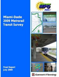
The image below demonstrates the network geometry for coding a dualized toll facility.<br />
FT = 99<br />
0.2 Mile<br />
Deceleration<br />
Link<br />
0.01 Mile<br />
<strong>Toll</strong> Plaza<br />
Link<br />
0.2 Mile<br />
Acceleration<br />
Link<br />
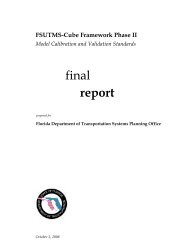
Additionally, cases may exist where an at-grade street has a toll plaza. At other times,<br />
some models may not make extensive use of dualized link coding. In such cases, the<br />
toll facility may not be coded as a dualized segment. Should this case arise, it is<br />
recommended that the modeler code the toll plaza as a hexagonal series of one-way<br />
links. This is demonstrated in the image below.<br />
9
<strong>Toll</strong> <strong>Facilities</strong> <strong>Model</strong>: <strong>Cube</strong> <strong>Voyager</strong> <strong>Version</strong><br />
FT = 99<br />
0.2 Mile<br />
Deceleration<br />
Link<br />
0.2 Mile<br />
Acceleration<br />
Link<br />
0.01 Mile<br />
<strong>Toll</strong> Plaza<br />
Link<br />
III. <strong>Toll</strong> FM Script<br />
The <strong>Toll</strong> FM is driven by a set of instructions coded into the highway assignment script<br />
of a model. In traditional travel demand models, there is at least one highway<br />
assignment component that is executed. The highway assignment script is responsible<br />
for loading vehicle trips onto the highway network. As a part of this process, the model<br />
must calculate traffic delay due to congestion in order to accurately assess the impact of<br />
such congestion on how the traffic loads onto the network. The <strong>Toll</strong> FM provides a<br />
method of calculating the delay caused by vehicles arriving at a toll plaza, stopping to<br />
pay their tolls, and accelerating to leave the toll plaza.<br />
The <strong>Toll</strong> FM should be present in any highway assignment script found in a model<br />
where toll facilities either currently exist or are being considered. Some models execute<br />
multiple highway assignments. In particular, transit models must run a preliminary<br />
highway assignment in order to generate congested skims needed to calculate mode<br />
choice. Additionally, time-of-day models may execute separate highway assignments<br />
for each time period being modeled. In such cases, each separate time period highway<br />
assignment script must contain the <strong>Toll</strong> FM. Other scripts may be written that can<br />
automate the process of modifying the highway network to contain the attributes needed<br />
for the <strong>Toll</strong> FM. These other scripts will not be discussed.<br />
Structure of Highway Program<br />
<strong>Cube</strong>’s HIGHWAY program is composed of five phases which are responsible for<br />
organizing the flow of the data processing that occurs when the model is run. The five<br />
phases that occur in the HIGHWAY program are discussed below in greater detail as<br />
they pertain to the <strong>Toll</strong> FM.<br />
10
<strong>Toll</strong> <strong>Facilities</strong> <strong>Model</strong>: <strong>Cube</strong> <strong>Voyager</strong> <strong>Version</strong><br />
SETUP – This phase initializes the arrays that will be used during execution of the <strong>Toll</strong><br />
FM script. There is no explicit header or control word that identifies the SETUP phase.<br />
Its existence is implied in the script before the PROCESS PHASE=LINKREAD<br />
statement that initiates the LINKREAD phase.<br />
LINKREAD – This phase loops through every link in the network and reads the values<br />
of each link’s attributes. Various calculations can be conducted during the LINKREAD<br />
phase that can modify the values of the existing variables and reserve those values for<br />
the purpose of conducting a highway assignment. All of the statements contained in the<br />
LINKREAD phase are known as the LINKREAD stack. This stack is executed for every<br />
link in the network when the LINKREAD phase is executed following the SETUP phase.<br />
This stack is also executed every time a link is read during the ADJUST phase that<br />
occurs later.<br />
ILOOP – This phase performs a loop through every zone in the network. This phase<br />
contains the PATHLOAD statements that actually load the volumes onto the network.<br />
All of the statements in the ILOOP phase are known as the ILOOP stack. The ILOOP<br />
stack is executed for every zone during the ILOOP phase.<br />
ADJUST – This phase calculates the congested time on each link in order to revise the<br />
link time values for the next iteration. ADJUST loops through every link which in turn<br />
causes the LINKREAD stack to execute anew for each link. The toll plaza delays<br />
caused by queuing as determined by the TOLL FM are input here in order to be<br />
incorporated into the congested travel time for the next iteration.<br />
CONVERGE – This phase can be used in order to override any default criteria used in<br />
determining when convergence is achieved. This allows the modeler greater control<br />
over the length and precision of model runs. In the absence of an explicit CONVERGE<br />
phase in the highway assignment script, the model will run until one of various default<br />
convergence criteria has been met. These criteria can be modified in the Parameters<br />
section of the SETUP phase. The CONVERGE phase is not critical to how the <strong>Toll</strong> FM<br />
is executed.<br />
After the assignment model passes through an initial SETUP phase and LINKREAD<br />
phase, the model passes from the ILOOP phase through the CONVERGE phase with<br />
each iteration. Only the phases from ILOOP through to CONVERGE are executed<br />
during each iteration. Note that execution of the ADJUST phase will execute the entire<br />
LINKREAD stack for each link as if a new LINKREAD phase had been initiated.<br />
Location of Key Elements<br />
The basic structure of the <strong>Toll</strong> FM script is embedded within a standard <strong>Cube</strong> <strong>Voyager</strong><br />
FSUTMS User Equilibrium assignment. A series of arrays are initialized during the<br />
11
<strong>Toll</strong> <strong>Facilities</strong> <strong>Model</strong>: <strong>Cube</strong> <strong>Voyager</strong> <strong>Version</strong><br />
SETUP phase. Of these arrays, some are used for calculating the toll delay in the<br />
model and others are used solely for debugging purposes. Each array is dimensioned<br />
to the number of links contained in the highway network. This allows for the<br />
hypothetical possibility of a toll on every link, though in practice this would not occur. It<br />
does grant the model a great level of flexibility in the number of tolls. All arrays used in<br />
the <strong>Toll</strong> FM are listed in Appendix A3 of this document.<br />
The principle attribute used to reference any particular slot of an array is the TOLL<br />
attribute found on the network. The TOLL attribute contains the toll plaza identification<br />
number for each plaza link. Each TOLL number is a unique value and each directional<br />
link of any given toll plaza should have a distinct value for TOLL. This means that if a<br />
plaza has an east-bound plaza link and a west-bound plaza link, that each link will have<br />
distinct TOLL number so that the east-bound TOLL number is different from the westbound<br />
TOLL number. The TOLL attribute for any given plaza link should also be the<br />
same value for corresponding acceleration and deceleration links.<br />
A look-up table is defined for the deceleration curve in the SETUP phase. This table<br />
has been set up to emulate the FSUTMS TRANPLAN <strong>Toll</strong> FM deceleration curve. The<br />
deceleration is a function of link speed. Depending on the link speed, an appropriate<br />
rate of deceleration will be selected in order to calculate the delay due to deceleration.<br />
The following is the deceleration look-up as it appears in the script:<br />
LOOKUP,<br />
INTERPOLATE=Y, LIST=Y, NAME=DECEL,<br />
LOOKUP[1]=1,RESULT=2,<br />
R = ' 0 2.35',<br />
'30 4',<br />
'70 6.2',<br />
'99 7.795'<br />
The numeric sequence “0, 30, 70, 99” represents speed in miles-per-hour and the<br />
sequence “2.35, 4, 6.2, 7.795” represents the rate of deceleration at the given speed.<br />
For any speed between 0 miles-per-hour and 99 miles-per-hour, the model will<br />
interpolate a rate of deceleration. The following chart illustrates the deceleration curve:<br />
12
<strong>Toll</strong> <strong>Facilities</strong> <strong>Model</strong>: <strong>Cube</strong> <strong>Voyager</strong> <strong>Version</strong><br />
The <strong>Toll</strong> FM calculations are divided into two overall groups: one for the initial iteration,<br />
and one for subsequent iterations. The calculations for the initial iteration are<br />
embedded within the LINKREAD phase of the highway assignment. This set of toll<br />
delay calculations are set to execute only during the initial iteration of the highway<br />
assignment model. The inclusion of the initial iteration synchronized the performance of<br />
the two software versions to better allow the <strong>Cube</strong> <strong>Voyager</strong> <strong>Toll</strong> FM to emulate the<br />
TRANPLAN <strong>Toll</strong> FM. Since there are no volumes on the network in the initial iteration,<br />
the toll delays at this point only consist of the acceleration delay, the deceleration delay,<br />
the impedance due to the coefficient of toll, and the service time at the plaza. There are<br />
no queuing delays at this point. These delays are used in the initial all-or-nothing<br />
iteration of the highway assignment.<br />
The subsequent iteration calculations are embedded in the ADJUST phase of the<br />
assignment model. These calculations are only executed beyond the initial iteration of<br />
the highway assignment. The calculations are processed using the volumes from the<br />
previous iteration in order to derive the delays. Unlike the initial iterations, the<br />
subsequent iterations of the assignment model have volumes on the networks.<br />
Therefore, the delays for the subsequent iterations include the acceleration delay, the<br />
deceleration delay, the impedance due to the coefficient of toll, the service time at the<br />
plaza, and the queuing delay. These delays are incorporated in the delay functions<br />
during the ADJUST phase and establish the TIME variable for the next iteration.<br />
Delay Calculations<br />
Deceleration: The deceleration delay is calculated for each link that is connected to a<br />
toll plaza link from the approaching direction when the toll plaza is not an open road toll<br />
plaza (i.e. Sunpass). The form of the deceleration delay is as follows:<br />
13
<strong>Toll</strong> <strong>Facilities</strong> <strong>Model</strong>: <strong>Cube</strong> <strong>Voyager</strong> <strong>Version</strong><br />
SPD X = DST / TIME * 60<br />
TT = SPD X / DEC X / 0.6<br />
D D = SPD X * 0.5 * TT / 60<br />
T D = (TT – ((D D / SPD X ) * 60)) / 100<br />
Where:<br />
SPD X = speed of the deceleration link<br />
DST = distance of the deceleration link<br />
TIME = travel time along the deceleration link (free-flow by default)<br />
TT = travel time of the deceleration<br />
DEC X = rate of deceleration at SPD X<br />
D D = deceleration delay<br />
T D = impedance added to TIME to calculate link congested travel<br />
time<br />
Below is a sample of the deceleration calculation from the script:<br />
; <strong>Toll</strong> Plaza Deceleration Link<br />
IF (LI.TOLL_DEC>0)<br />
LINKCLASS=5<br />
;Deceleration Lane (AB)<br />
IF (LI.TOLL>0 & LI.TOLL_ACC=0 & LI.TOLL_DEC=1)<br />
IF (LI.TIME=0)<br />
TT1[LI.TOLL]=0<br />
DD1[LI.TOLL]=0<br />
SPDAB[LI.TOLL]=1<br />
ELSE<br />
SPDAB[LI.TOLL]= DISTANCE/LI.TIME*60<br />
DISTAB[LI.TOLL]=DISTANCE<br />
TIMEAB[LI.TOLL]=LI.TIME<br />
TT1[LI.TOLL]= SPDAB[LI.TOLL]/DECEL(1,SPDAB[LI.TOLL])/0.6<br />
DD1[LI.TOLL]= SPDAB[LI.TOLL]*0.5*TT1[LI.TOLL]/60<br />
ENDIF<br />
ENDIF<br />
TD=(TT1[LI.TOLL]-((DD1[LI.TOLL]/SPDAB[LI.TOLL])*60))/100<br />
T0=TD+T0<br />
TDEC[LI.TOLL]=TD<br />
TIMT1[LI.TOLL]=LI.TIME<br />
VTPLT1[LI.TOLL]=V<br />
LISPD1[LI.TOLL]=SPDAB[LI.TOLL]<br />
ENDIF<br />
Acceleration: The acceleration delay is calculated for each link that is connected to a<br />
toll plaza link from the receding direction when the toll plaza is not an open road toll<br />
plaza (i.e. Sunpass). The form of the acceleration delay is as follows:<br />
SPD X = DST / TIME * 60<br />
TT = SPD X / 2.5 / 0.6<br />
D A = SPD X * 0.5 * TT / 60<br />
T A = (TT – ((D A / SPD X ) * 60)) / 100<br />
14
<strong>Toll</strong> <strong>Facilities</strong> <strong>Model</strong>: <strong>Cube</strong> <strong>Voyager</strong> <strong>Version</strong><br />
Where:<br />
SPD X = speed of the acceleration link<br />
DST = distance of the acceleration link<br />
TT = travel time of the acceleration<br />
TIME = travel time along the acceleration link (free-flow by default)<br />
D A = acceleration delay<br />
T A = impedance added to TIME to calculate link congested travel<br />
time<br />
Below is a sample of the acceleration calculation from the script:<br />
; <strong>Toll</strong> Plaza Acceleration Link<br />
IF (LI.TOLL_ACC>0)<br />
LINKCLASS=4<br />
;Acceleration Lane (CD)<br />
IF (LI.TOLL>0 & LI.TOLL_ACC=1 & LI.TOLL_DEC=0)<br />
IF (LI.TIME=0)<br />
TT3[LI.TOLL]=0<br />
DD3[LI.TOLL]=0<br />
SPDCD[LI.TOLL]=1<br />
ELSE<br />
SPDCD[LI.TOLL]= DISTANCE/LI.TIME*60<br />
DISTCD[LI.TOLL]=DISTANCE<br />
TIMECD[LI.TOLL]=LI.TIME<br />
TT3[LI.TOLL]= SPDCD[LI.TOLL]/2.5/0.6<br />
DD3[LI.TOLL]= SPDCD[LI.TOLL]*0.5*TT3[LI.TOLL]/60<br />
ENDIF<br />
ENDIF<br />
TA=(TT3[LI.TOLL]-((DD3[LI.TOLL]/SPDCD[LI.TOLL])*60))/100<br />
T0=TA+T0<br />
TACC[LI.TOLL]=TA<br />
TIMT3[LI.TOLL]=LI.TIME<br />
VTPLT3[LI.TOLL]=V<br />
LISPD3[LI.TOLL]=SPDCD[LI.TOLL]<br />
ENDIF<br />
Plaza Queuing Delay: The queuing delays for the toll plazas are calculated for each<br />
toll plaza link in the network that is not an open road toll plaza. The model can be set to<br />
accommodate either multi-server queues or single server queues. Please note that the<br />
λ used for toll delay is not the same λ searched for during user equilibrium adjustments<br />
described in the appendix. The form of the multi-server queue delay is as follows:<br />
15
<strong>Toll</strong> <strong>Facilities</strong> <strong>Model</strong>: <strong>Cube</strong> <strong>Voyager</strong> <strong>Version</strong><br />
µ = 1 / (SERVT / 60)<br />
UTIL = λ / µ<br />
USER = UTIL / SER<br />
SER-1<br />
PPO = ∑ ((UTIL N ) / N!)<br />
N=1<br />
TP =<br />
1<br />
PPO + UTIL SER / ((SER-1)! * SER * (1 – USER))<br />
SER * (SER-1)! * (1-USER) 2<br />
λ<br />
* UTIL SER * USER<br />
* RATIO + (1/µ) * 6000<br />
Where:<br />
SERVT = service time in minutes at the plaza<br />
λ = volume on the plaza<br />
SER = maximum number of lanes on the plaza link<br />
RATIO = 1<br />
TP = queuing delay at the plaza<br />
If the value of USER > 0.99, then λ and RATIO will need to be recalculated as follows<br />
before calculating PPO:<br />
Where:<br />
λ = µ * SER * 0.99<br />
RATIO = VOL / λ<br />
VOL = volume at peak hour on the plaza link (if daily model, it is<br />
volume * Peak-to-Daily factor (CONFAC))<br />
If at any point λ = 0, then TP will instead be calculated as follows:<br />
TP = 6000 / µ<br />
If the single server queue option of the model is selected, then the calculation for the toll<br />
plaza queuing delay is simplified. The form of the single server queue delay is as<br />
follows:<br />
16
<strong>Toll</strong> <strong>Facilities</strong> <strong>Model</strong>: <strong>Cube</strong> <strong>Voyager</strong> <strong>Version</strong><br />
λ = VOL / SER<br />
µ = 1 / (SERVT / 60)<br />
TP = (1 / (µ – λ)) * 6000<br />
Where:<br />
VOL = volume on the plaza link<br />
SER = maximum number of lanes on the plaza link<br />
SERVT = service time in minutes at the plaza<br />
If the value of λ > (0.99 * µ), then λ will need to be recalculated as follows:<br />
λ = 0.99 * µ<br />
Regardless of whether the multi-server or single server queue options have been<br />
selected, a maximum impedance value has been set for TP. If the value of TP<br />
>1,333.33, then TP is recalculated as follows:<br />
TP = 1333.33<br />
Below is a sample of the toll plaza queuing delay calculation from the script:<br />
IF (LI.TOLL>0 & LI.TOLL_ACC=0 & LI.TOLL_DEC=0)<br />
ITER[LI.TOLL]=ITERATION<br />
ALINK[LI.TOLL]=A<br />
BLINK[LI.TOLL]=B<br />
VOLBC[LI.TOLL]=V * LI.CONFAC<br />
TT4[LI.TOLL]= {CTOLL}*LI.CARTOLL*{CTOLLSCALE}*100<br />
ENDIF<br />
IF (LI.TOLLTYPE=1,2)<br />
IF ({QUEUETYPE}=1) ; MULTIPLE SERVER QUEUE MODEL<br />
LAM[LI.TOLL]= VOLBC[LI.TOLL]<br />
MU[LI.TOLL] = 1/(LW.SERVT/60)<br />
UTIL[LI.TOLL]=LAM[LI.TOLL]/MU[LI.TOLL]<br />
UTLSER[LI.TOLL]=UTIL[LI.TOLL]/LI.PLZALNSMAX<br />
SER[LI.TOLL]=LI.PLZALNSMAX<br />
PP0[LI.TOLL]=1<br />
REALN[LI.TOLL]=1<br />
NLANE1=LI.PLZALNSMAX-1<br />
RATIO[LI.TOLL]=1<br />
IF (UTLSER[LI.TOLL]>0.99) ; CHECK AGAINST MAXUTL<br />
LAM[LI.TOLL]= MU[LI.TOLL]*SER[LI.TOLL]*0.99<br />
RATIO[LI.TOLL]= VOLBC[LI.TOLL]/LAM[LI.TOLL]<br />
UTIL[LI.TOLL]= LAM[LI.TOLL]/MU[LI.TOLL]<br />
UTLSER[LI.TOLL]= UTIL[LI.TOLL]/SER[LI.TOLL]<br />
ENDIF<br />
17
<strong>Toll</strong> <strong>Facilities</strong> <strong>Model</strong>: <strong>Cube</strong> <strong>Voyager</strong> <strong>Version</strong><br />
LOOP NN=1,NLANE1<br />
REALI=NN<br />
REALN[LI.TOLL]= REALN[LI.TOLL]* REALI<br />
PP0[LI.TOLL]=PP0[LI.TOLL]+(UTIL[LI.TOLL]^REALI)/REALN[LI.TOLL]<br />
ENDLOOP<br />
PP0[LI.TOLL]=1/(PP0[LI.TOLL]+(UTIL[LI.TOLL]^SER[LI.TOLL])/<br />
(REALN[LI.TOLL]*SER[LI.TOLL]*(1-UTLSER[LI.TOLL])))<br />
TT2[LI.TOLL]= PP0[LI.TOLL] * UTIL[LI.TOLL]^SER[LI.TOLL] *<br />
UTLSER[LI.TOLL]<br />
TT2[LI.TOLL]= TT2[LI.TOLL] / (SER[LI.TOLL]* REALN[LI.TOLL] *<br />
((1-UTLSER[LI.TOLL])^2))<br />
IF (LAM[LI.TOLL]=0)<br />
TT2[LI.TOLL]= 6000/MU[LI.TOLL]<br />
ELSE<br />
TT2[LI.TOLL]=(TT2[LI.TOLL]/LAM[LI.TOLL]*RATIO[LI.TOLL]+1/MU[LI.TOLL])*<br />
6000<br />
ENDIF<br />
DD2[LI.TOLL]=0<br />
ELSE ; SINGLE SERVER QUEUE MODEL<br />
LAM[LI.TOLL]=VOLBC[LI.TOLL]/LI.PLZALNSMAX<br />
MU[LI.TOLL]= 1/(LW.SERVT/60)<br />
IF (LAM[LI.TOLL]>(0.99*MU[LI.TOLL])) LAM[LI.TOLL]=(0.99*MU[LI.TOLL]);<br />
CHECK AGAINST MAXUTL<br />
UTIL[LI.TOLL]=LAM[LI.TOLL]/MU[LI.TOLL]<br />
AVEQUE[LI.TOLL]=MU[LI.TOLL]/(MU[LI.TOLL]-LAM[LI.TOLL])<br />
DD2[LI.TOLL]= AVEQUE[LI.TOLL]*35/5280*100; CARLTH=35 FEET<br />
TT2[LI.TOLL]=1/(MU[LI.TOLL]-LAM[LI.TOLL])*6000<br />
ENDIF<br />
IF (TT2[LI.TOLL]>1333.33) TT2[LI.TOLL]=1333.33<br />
Open Road <strong>Toll</strong>ing: In a model with open road tolling, there is no queuing delay at the<br />
toll plazas. The model has been designed to accommodate a mix of plaza types. <strong>Toll</strong><br />
plaza links may be coded as either traditional toll plazas or open road plazas. Care<br />
must be taken when using a combination of traditional and open road toll plaza types<br />
either along the same facility, along competing facilities, or at the same plaza, Because<br />
open road toll plazas do not have acceleration/deceleration delays or queuing delays,<br />
open road toll plazas will tend to out-perform traditional plazas. The modeler is<br />
responsible to restrict the usage of the open road tolling plazas to transponder equipped<br />
trips or those who can properly use the plaza. While no particular method has been<br />
widely developed in Florida to accomplish this, future research into toll modeling<br />
enhancements may consider the use of toll choice models to distinguish open road toll<br />
users from barrier users. .When calculating volume delays open road tolling plazas only<br />
contribute impedance due to the value of toll.<br />
18
<strong>Toll</strong> <strong>Facilities</strong> <strong>Model</strong>: <strong>Cube</strong> <strong>Voyager</strong> <strong>Version</strong><br />
Below is a sample of the calculation for delays at open road toll plazas from the script.<br />
IF (LI.TOLLTYPE=3)<br />
LINKCLASS=3 ; with ORT<br />
T0=({CTOLL}*LI.CARTOLL)*{CTOLLSCALE}<br />
ENDIF<br />
Impedance Due to the Value of <strong>Toll</strong>: The impedance due to the value of toll<br />
measures the perceived impact of the cost of a toll to trip making behavior. This<br />
impedance is calculated by applying a coefficient of toll to the toll price at each plaza.<br />
The resulting value is a generalized cost in terms of travel times in minutes. This<br />
generalized cost is then added to the delay equation for the toll plaza link. The form of<br />
the impedance due to the value of toll is as follows:<br />
Where:<br />
CTOLL = 1 / (WRATE * A)<br />
CT = (CTOLL * PRICE) * CTOLLSCALE<br />
CTOLL = coefficient of toll<br />
CTOLLSCALE = coefficient of toll scaling factor<br />
WRATE = average wage rate of the study area<br />
A = proportion relevant to route choice (30% to 40%)<br />
PRICE = price of toll at the toll plaza<br />
CT = impedance due to the value of toll<br />
Typically, the value of CTOLL is calculated by hand before the model is executed and<br />
input into the model as a parameter. The value of CTOLLSCALE depends on the<br />
definition of the units of CTOLL, as the model operates using minutes, if CTOLL for<br />
example represents the time equivalent of hours per dollar, CTOLLSCALE will have to<br />
be 60 to convert the hours to minutes. As mentioned in the previous section, the<br />
coefficient of toll scale should be determined by the implementing agency based on<br />
their interpretation of local survey results and statistics.<br />
19
<strong>Toll</strong> <strong>Facilities</strong> <strong>Model</strong>: <strong>Cube</strong> <strong>Voyager</strong> <strong>Version</strong><br />
Adjust<br />
At the end of every iteration of the highway assignment model, new congested times<br />
are calculated. These congested times are used to calculate new paths for the volume<br />
loading in the next iteration. Along with the standard Bureau of Public Roads volume<br />
delay function used to calculate congested times on highway links without tolls, four<br />
additional functions have been included in order to account for delay caused by toll<br />
plazas.<br />
The toll plazas themselves use one of two functions depending on whether a toll plaza<br />
is an open road toll plaza. The form for a traditional toll plaza is as follows:<br />
Where:<br />
TC = (TP / 100) + CT<br />
TP = queuing delay at the plaza as calculated above<br />
CT = impedance due to the value of toll<br />
TC = congested travel time<br />
The form for an open road toll plaza is as follows:<br />
Where:<br />
TC = CT<br />
CT = impedance due to the value of toll<br />
TC = congested travel time<br />
Two separate functions are used to calculate delays on the acceleration and<br />
deceleration links. The form for the acceleration links is as follows:<br />
Where:<br />
TC = TIME + T A<br />
TIME = travel time along the acceleration link (free-flow by default)<br />
T A = impedance of the acceleration delay as calculated above<br />
TC = congested travel time<br />
The form for the deceleration links is as follows:<br />
Where:<br />
TC = TIME + T D<br />
20
<strong>Toll</strong> <strong>Facilities</strong> <strong>Model</strong>: <strong>Cube</strong> <strong>Voyager</strong> <strong>Version</strong><br />
TIME = time along the deceleration link (free-flow by default)<br />
T D = impedance of the deceleration delay as calculated above<br />
TC = congested travel time<br />
Below is a sample of calculating congested time for the four toll links described above<br />
from the ADJUST phase of the script.<br />
FUNCTION TC[2]=(TT2[LI.TOLL]+TT4[LI.TOLL])/100; delay for toll links<br />
FUNCTION TC[3]=({CTOLL}*LI.CARTOLL)*{CTOLLSCALE} ; delay on ORT toll links<br />
FUNCTION TC[4]=LI.TIME+((TT3[LI.TOLL]-<br />
((DD3[LI.TOLL]/SPDCD[LI.TOLL])*60))/100); congested time acceleration links<br />
FUNCTION TC[5]=LI.TIME+((TT1[LI.TOLL]-<br />
((DD1[LI.TOLL]/SPDAB[LI.TOLL])*60))/100); congested time deceleration links<br />
It is important to note that the total delay due to tolling is spread over all three links<br />
associated with any given toll plaza. Each component of the calculated delay is<br />
retained on the link where the delay actually occurs. This means that the congested<br />
travel times for a given acceleration link already incorporate the acceleration delay from<br />
the <strong>Toll</strong> FM. The same is true for the deceleration delay. In the previous TRANPLAN<br />
version of the <strong>Toll</strong> FM, all of the components of toll delay were aggregated onto the toll<br />
plaza link itself. This means that if one is attempting to compare results from a <strong>Cube</strong><br />
<strong>Voyager</strong> model and an older TRANPLAN model, it will be necessary to combine the<br />
congested travel times of all three associated toll links from <strong>Cube</strong> <strong>Voyager</strong> and compare<br />
this to the congested travel time on the toll plaza link from TRANPLAN.<br />
The non toll link congested time is calculated by the following function with the<br />
commonly used BPR equation. The catalog key VCMAX is utilized here as the limiting<br />
allowable volume over capacity ratio as the maximum BPR exponent. The typical value<br />
for an urban area is four (4) and ten (10) for a rural area. As mentioned in the previous<br />
section this value should be determined by the implementing agency based on their<br />
local traffic characteristics and uniqueness of transportation system.<br />
FUNCTION TC[1]={DAMPINGFACTOR}*LW.PREVTIME+(1.0-<br />
{DAMPINGFACTOR})*LI.TIME*(1+LI.BPRCOEFFICIENT*MIN((V/C),{VCMax})^<br />
LI.BPREXPONENT)<br />
21
<strong>Toll</strong> <strong>Facilities</strong> <strong>Model</strong>: <strong>Cube</strong> <strong>Voyager</strong> <strong>Version</strong><br />
IV. Conclusion<br />
As agencies in Florida continue to identify shortfalls for meeting their transportation<br />
needs, tolling may increasingly be considered as a viable funding alternative. As a<br />
result, the practice of toll modeling in Florida may become more prevalent. In order to<br />
meet this rising demand for toll modeling, methodologies such as the <strong>Toll</strong> FM will need<br />
to be continuously developed, tested, and refined.<br />
The <strong>Toll</strong> FM has been the default method for modeling toll trips throughout the state of<br />
Florida for years. The conversion of the <strong>Toll</strong> FM into a format compatible with <strong>Cube</strong><br />
<strong>Voyager</strong> will allow modelers in the state of Florida to continue to reasonably forecast the<br />
performance of toll facilities. This document provided guidance on how the <strong>Toll</strong> FM<br />
functions so that the modeler can understand the process by which delays are<br />
calculated at the toll plazas. With this understanding, it should be possible to apply the<br />
<strong>Toll</strong> FM to any model in the State of Florida and to accurately assess the results that are<br />
produced.<br />
The <strong>Toll</strong> FM as it currently exists in <strong>Cube</strong> <strong>Voyager</strong> is a faithful reproduction of the<br />
original TRANPLAN application with the multi-server queue feature. Future studies into<br />
toll behavior may reveal that modifications to the model may be desirable.<br />
Investigations into methods of using ramp-to-ramp tolling for modeling purposes may<br />
require that changes be made to the structure of the <strong>Toll</strong> FM. Further enhancements to<br />
the <strong>Toll</strong> FM should be investigated to determine what improvements can be made to the<br />
model.<br />
22
<strong>Toll</strong> <strong>Facilities</strong> <strong>Model</strong>: <strong>Cube</strong> <strong>Voyager</strong> <strong>Version</strong><br />
Appendixes<br />
A1. Software Differences<br />
During the process of converting the <strong>Toll</strong> FM into <strong>Cube</strong> <strong>Voyager</strong>, the Florida<br />
Department of Transportation conducted a series of tests that were used to monitor the<br />
progress of the conversion effort. The Department used the Olympus training model as<br />
a test bed. The purpose of these tests was to ensure that model calculations were<br />
being performed consistently between the TRANPLAN and <strong>Cube</strong> <strong>Voyager</strong> software<br />
platforms. Since Olympus was developed in <strong>Cube</strong>, the model’s highway network and<br />
trip tables were converted into a format that could be understood by FSUTMS<br />
TRANPLAN. The trip tables remained consistent and all tests involved multiple<br />
executions of only the highway assignment. Since the purpose of this effort was to<br />
faithfully reproduce the <strong>Toll</strong> FM in <strong>Cube</strong> <strong>Voyager</strong>, the tests focused on the mathematical<br />
computations of the <strong>Toll</strong> FM and the resulting values. The testers paid particular<br />
attention to travel times, delays, and volumes. No regard was given to whether reported<br />
volumes were reasonable in and of themselves so long as the results were reasonably<br />
consistent between the two platforms. The <strong>Toll</strong> FM was executed in FSUTMS<br />
TRANPLAN, <strong>Cube</strong> <strong>Voyager</strong>, and on an Excel spreadsheet.<br />
With the change in modeling software from TRANPLAN to <strong>Cube</strong> <strong>Voyager</strong>, it was<br />
inevitable that differences in the programs that executed the models would produce<br />
different results. In some cases, these differences were relatively minor. In other<br />
instances, the differences were more noticeable. It is important to note that in no case<br />
do these differences imply any deficiencies with either the older or newer modeling<br />
methodologies. They are merely the consequence of differing, yet equally viable<br />
mathematical methods to arrive at the solutions required for travel demand modeling.<br />
With the advent of more powerful computers in the market place, many of the<br />
programming and mathematical shortcuts that were required in the past could be<br />
eliminated. The most significant changes are the changes in memory: (1) internal<br />
memory limitations led to “bit-packing” which could not be done with REAL numbers;<br />
and (2) external memory – disc space. These allow for more precise mathematical<br />
computations that explain many of the differences between how TRANPLAN and <strong>Cube</strong><br />
<strong>Voyager</strong> perform.<br />
Floating Point Math<br />
Perhaps the most significant difference between the two software versions is that <strong>Cube</strong><br />
<strong>Voyager</strong> is designed to calculate floating point math. Due to the software and<br />
23
<strong>Toll</strong> <strong>Facilities</strong> <strong>Model</strong>: <strong>Cube</strong> <strong>Voyager</strong> <strong>Version</strong><br />
computing limitations at the time when FSUTMS was first developed, travel demand<br />
models in the State of Florida relied on integer math. All mathematical solutions were<br />
rounded to the nearest integer. By the time that <strong>Cube</strong> <strong>Voyager</strong> was adopted as the<br />
travel demand software platform for Florida, this had ceased to be a concern. As a<br />
result, all calculations conducted in <strong>Cube</strong> <strong>Voyager</strong> use double precision floating point<br />
variables.<br />
Given the size and complexity of a particular model, the compound effect of using real<br />
numbers in the model’s calculations can yield results that differ with the TRANPLAN<br />
version of the model to a greater or lesser extent. Larger zone systems produce larger<br />
matrices. More complex networks require a larger number of links. In each case, every<br />
additional link or matrix cell increases the number of calculations performed by the<br />
model. Every calculation is an opportunity for the difference between integers and real<br />
numbers to compound. When reviewing the performance of a <strong>Cube</strong> <strong>Voyager</strong> model<br />
against the results of its TRANPLAN predecessor, the analyst should not rely on a<br />
straight comparison of the results. Rather, the analyst should determine the<br />
reasonableness of the mathematical computations of the model in both software<br />
platforms to ensure that they correspond with the intended methodology. If the<br />
computations prove to be sound, then the differences between the integers and the real<br />
numbers should be easy to identify. One way to do this would be to take a small portion<br />
of the model and work out the calculations in a spreadsheet. The spreadsheet could be<br />
set up to do the same calculations using both floating point math and bucket rounding.<br />
The results of the spreadsheet calculations can then be compared to the results<br />
developed by the modeling software.<br />
Path Building<br />
Both TRANPLAN and <strong>Cube</strong> <strong>Voyager</strong> build highway paths in a similar manner with one<br />
notable exception. When the model is confronted with a set of multiple paths between<br />
any two points, the model will select the path with the least generalized cost. Typically,<br />
the generalized cost is measured in units of time, though the user could instead specify<br />
distance or a composite impedance. This is true for both software packages. At times,<br />
the model will identify two paths with equal generalized costs. When this happens, the<br />
model will select the path based on the relative sequence of the node numbers for the<br />
nodes immediately connected to the point where the path diverges. For example, given<br />
two paths A-B-D and A-C-D which are of equal cost, the model will select the path<br />
depending on whether the number of node B is higher or lower than the number of node<br />
C. TRANPLAN will prefer the path where the node number corresponding to either B or<br />
C is higher. <strong>Cube</strong> <strong>Voyager</strong> will prefer the path where the node number corresponding<br />
24
<strong>Toll</strong> <strong>Facilities</strong> <strong>Model</strong>: <strong>Cube</strong> <strong>Voyager</strong> <strong>Version</strong><br />
to either B or C is lower. Therefore, if B = 101 and C = 105, then TRANPLAN will select<br />
path A-C-D and <strong>Cube</strong> <strong>Voyager</strong> will prefer path A-B-D.<br />
There is typically minimal impact systemwide to the model’s results due to this<br />
difference. At a corridor level, this impact may be more or less noticeable. Once again,<br />
when comparing models between TRANPLAN and <strong>Cube</strong> <strong>Voyager</strong> versions, it is<br />
important to compare and assess the methodologies and not merely the numerical<br />
results.<br />
Lambda Search<br />
When conducting a User Equilibrium Assignment, the model apportions the trips going<br />
between any given origin and destination pair among the various paths connecting that<br />
pair. The model uses a criterion of apportioning the trips throughout the network in such<br />
a manner as to not increase the net impact of congestion on the network systemwide.<br />
When no further changes can be made to how the trips are distributed throughout the<br />
highway network without increasing the net impact to the system, equilibrium has been<br />
achieved. The trips are apportioned by means of a factor known as Lambda (λ).<br />
Please note that this is not the same λ that was discussed earlier in this document when<br />
describing the method for calculating queuing delay.<br />
The value of λ is equal to the factor that would need to be applied to the volumes during<br />
the adjustment phase of the assignment in order to achieve equilibrium. It is not<br />
possible to solve for λ directly. Therefore, λ must be approximated using one of several<br />
techniques designed for this purpose. While this document will not go into detail on the<br />
various techniques that can be used for approximating λ, it is important to note that<br />
TRANPLAN and <strong>Cube</strong> <strong>Voyager</strong> both use different methods. As a consequence, the<br />
apportioning of trips along the highway network under congested conditions will be<br />
different between the two software platforms. These differences are inherent to the<br />
methodologies used by each platform to approximate the value of λ. The differences in<br />
assigned volumes due to λ are more noticeable in congested areas and congested<br />
corridors. Once again, it is important to establish the reasonableness of the model’s<br />
results based on the methodologies employed and not merely on a strict comparison of<br />
the numerical results of the TRANPLAN and <strong>Cube</strong> <strong>Voyager</strong> versions of the model.<br />
A2. FSUTMS TRANPLAN <strong>Toll</strong> Facility <strong>Model</strong> FORTRAN Source Code<br />
As mentioned in the previous section, the conversion of the <strong>Toll</strong> FM into <strong>Cube</strong> <strong>Voyager</strong><br />
attempts to maintain methodological fidelity with the original application used in<br />
FSUTMS TRANPLAN. As a result, the new <strong>Toll</strong> FM represents a literal translation of its<br />
predecessor into the new format. All calculations and data requirements remain<br />
consistent with the original TRANPLAN <strong>Toll</strong> FM.<br />
25
<strong>Toll</strong> <strong>Facilities</strong> <strong>Model</strong>: <strong>Cube</strong> <strong>Voyager</strong> <strong>Version</strong><br />
Below is the toll facility model code from the original SETOLL.FOR FORTRAN<br />
subroutine:<br />
SUBROUTINE SETOLL(CODE,DISTAB,TIMEAB,DISTCD,TIMECD,VOLBC,DELAY,<br />
1 T4,UTIL,LSTLAM)<br />
IMPLICIT INTEGER*2 (A-Z)<br />
C<br />
C ROUTINE TO CALCULATE THE DELAY AT A TOLL FACILITY<br />
C<br />
C<br />
WRITTEN BY JIM FENNESSY, THE URBAN ANALYSIS GROUP<br />
C MARCH, 1991<br />
C<br />
C<br />
FOR FLORIDA DOT, TURNPIKE<br />
C<br />
C (INPUTS) -- TPLANE = NUMBER OF LANES<br />
C<br />
-- TPMXLN = MAXIMUM NUMBER OF PERMISSIBLE LANES<br />
C<br />
-- TPTYPE = 1 -- ACCEL/DECEL (BARRIER)<br />
C<br />
2 -- NO ACCEL/DECEL (RAMP)<br />
C<br />
-- TPTOLL = TOLL IN DOLLARS (CONVERTED TO MINUTES*100)<br />
C<br />
-- TPCASH = TOLL IN DOLLARS<br />
C -- TPSERV = SERVICE TIME IN SECONDS / 3600.0<br />
C<br />
-- TPTRUK = PROPORTION OF HEAVY TRUCKS<br />
C<br />
-- TPEXCL = NUMBER OF EXACT CHANGE LANES<br />
C<br />
-- TPAVIL = NUMBER OF AVI LANES<br />
C<br />
-- TPDECC = DECELERATION CODE<br />
C<br />
-- TPACCC = ACCELERATION CODE<br />
C<br />
-- TPDCAR = CAR DECELERATION (SPEED, RATE)<br />
C<br />
-- TPDTRK = TRUCK DECELERATION (SPEED, RATE)<br />
C<br />
-- TPACAR = CAR ACCELERATION (SPEED, RATE)<br />
C<br />
-- TPATRK = TRUCK ACCELERATION (SPEED, RATE)<br />
C<br />
-- CARLTH = CAR LENGTH IN FEET<br />
C<br />
-- TRKLTH = TRUCK LENGTH IN FEET<br />
C<br />
-- TOLLA = A-NODE OF TOLL FACILITY<br />
C<br />
-- TOLLB = B-NODE OF TOLL FACILITY<br />
C<br />
-- TOLSYS = .TRUE. IF TOLL FACILITIES MODEL<br />
C<br />
-- TPIDEN = TOLL LOCATION ID<br />
C<br />
C<br />
-- NUMTOL = NUMBER OF TOLL FACILITIES INPUT<br />
C<br />
C<br />
-- DECDST = DECELERATION LINK DISTANCE<br />
C<br />
-- DECTIM = DECELERATION LINK TIME<br />
C<br />
-- ACCDST = ACCELERATION LINK DISTANCE<br />
C<br />
-- ACCTIM = ACCELERATION LINK TIME<br />
C<br />
-- TPOTIM = PREVIOUS ITERATION TOLL LINK TIME<br />
C<br />
C CODE -- FACILITY NUMBER ON THE TOLLLINK FILE<br />
C DISTAB -- DISTANCE ON DECELERATION LINK<br />
C TIMEAB -- TIME ON DECELERATION LINK<br />
C DISTCD -- DISTANCE ON ACCELERATION LINK<br />
C TIMECD -- TIME ON ACCELERATION LINK<br />
C VOLBC -- TRIP VOLUME AT TOLL FACILITY<br />
C TOLLA -- A-NODE OF TOLL FACILITY<br />
C TOLLB -- B-NODE OF TOLL FACILITY<br />
C<br />
C<br />
LSTLAM -- IF TRUE, THIS IS THE END OF THE LAMBDA ASSIGNMENT LOOP<br />
26
<strong>Toll</strong> <strong>Facilities</strong> <strong>Model</strong>: <strong>Cube</strong> <strong>Voyager</strong> <strong>Version</strong><br />
C MULTIQ -- IF TRUE, MULTIPLE SERVER QUEUE (IF FALSE, SINGLE)<br />
C ACCQUE -- IF TRUE, "ACCUMULATE QUEUE" PARAMETER: DEFAULT = FALSE<br />
C INCTOL -- IF TRUE, INCLUDE TOLL COST (AS TIME)<br />
C GENERAL -- IF TRUE, GENERAL COST APPLICATION<br />
C TOLDIV -- IF TRUE, TOLL DIVERSION ASSIGNMENT APPLICATION<br />
C<br />
(NO TOLL / NON-TOLL INPUT TRIPS)<br />
C OPENRD -- IF TRUE, OPEN ROAD TOLLING AT TOLL FACILITY<br />
C FRETOL -- IF TRUE, ASSUMES NO DELAY -- "WHAT IF" OPTION<br />
C TOLLDB -- "TOLL DEBUG" OPTION: DEFAULT IS FALSE<br />
C MAXUTL -- "MAXIMUM UTILIZATION" PARAMETER: DEFAULT = 0.99<br />
C MAXQT -- "TOLL QUEUE MAXIMUM" PARAMETER: DEFAULT = 100.O MIN<br />
C LIMQT -- "TOLL QUEUE LIMIT" PARAMETER: DEFAULT = 10.0 MIN<br />
C<br />
INCLUDE 'paramter.inc'<br />
INCLUDE 'luncom.inc'<br />
INCLUDE 'equilb.inc'<br />
INCLUDE 'equilb1.loc'<br />
INCLUDE 'toll.loc'<br />
C<br />
REAL*4 VOLBC,DELAY,UTIL,D1,D2,D3,T1,T2,T3,T4,MU,LAM,AVEQUE,<br />
1 SPDAB,SPDCD,ACCEL,DECEL,R1,R2,SER,REALI,REALN,P0,UTLSER,<br />
2 RATIO<br />
INTEGER*4 VOL1,VOL2<br />
LOGICAL*2 LSTLAM<br />
C<br />
NODEA = IABS(TOLLA(CODE))<br />
C<br />
C THE DELAY CONSISTS OF THREE COMPONENTS:<br />
C<br />
C T1 = DECELERATION DELAY<br />
C T2 = TOLL BOOTH QUE DELAY<br />
C T3 = ACCELERATION DELAY<br />
C T4 = TOLL COST (AS TIME)<br />
C<br />
C GET THE TOLL COST CONVERTED TO TIME<br />
C<br />
IF (TOLDIV.AND..NOT.TOLSYS) THEN<br />
T4 = 0.0<br />
ELSE<br />
IF (TOLDIV) THEN<br />
IF (INCTOL) THEN<br />
T4 = TPTOLL(CODE)<br />
ELSE<br />
T4 = 0.0<br />
ENDIF<br />
ELSE<br />
T4 = TPTOLL(CODE)<br />
ENDIF<br />
ENDIF<br />
IF (GENERAL) T4 = 0.0<br />
C<br />
C CHECK IF NO ACCEL/DECEL CONDITIONS<br />
C<br />
IF (TPTYPE(CODE).EQ.2) THEN<br />
SPDAB = 0.0<br />
SPDCD = 0.0<br />
T1 = 0.0<br />
27
<strong>Toll</strong> <strong>Facilities</strong> <strong>Model</strong>: <strong>Cube</strong> <strong>Voyager</strong> <strong>Version</strong><br />
T2 = 0.0<br />
T3 = 0.0<br />
D1 = 0.0<br />
D2 = 0.0<br />
D3 = 0.0<br />
AVEQUE = 0.0<br />
LAM = 0.0<br />
MU = 0.0<br />
DELAY = T4<br />
UTIL = 0.0<br />
ELSE<br />
C<br />
C WORK ON DECELERATION DELAY -- CARS FOR NOW<br />
C<br />
IF (TIMEAB.EQ.0) THEN<br />
T1 = 0.0<br />
D1 = 0.0<br />
SPDAB = 1.0<br />
ELSE<br />
DCODE = TPDECC(CODE)<br />
SPDAB = FLOAT(DISTAB) / FLOAT(TIMEAB) * 60.0<br />
IF (TPDCAR(1,DCODE).EQ.TPDCAR(3,DCODE)) THEN<br />
DECEL = TPDCAR(2,DCODE)<br />
ELSE<br />
DECEL = TPDCAR(2,DCODE) + (TPDCAR(4,DCODE)-TPDCAR(2,DCODE))<br />
1 / (TPDCAR(3,DCODE)-TPDCAR(1,DCODE))<br />
2 * ( SPDAB -TPDCAR(1,DCODE))<br />
ENDIF<br />
T1 = SPDAB / DECEL / 0.6<br />
D1 = SPDAB * 0.5 * T1 / 60.0<br />
ENDIF<br />
C<br />
C CHECK THE TYPE OF QUEUING MODEL<br />
C<br />
SER = TPLANE(CODE)<br />
IF (MULTIQ.AND.TPLANE(CODE).GT.1) THEN<br />
C<br />
C MULTIPLE SERVER QUEUE MODEL<br />
C<br />
NLANE1 = TPLANE(CODE) - 1<br />
LAM = VOLBC<br />
MU = 1.0 / TPSERV(CODE)<br />
UTIL = LAM / MU<br />
UTLSER = UTIL / SER<br />
RATIO = 1.0<br />
C<br />
C CHECK AGAINST "MAXUTL"<br />
C<br />
IF (UTLSER.GT.MAXUTL) THEN<br />
IF (ACCQUE) THEN<br />
LAM = MU * SER * MAXUTL<br />
RATIO = VOLBC / LAM<br />
VOL1 = LAM + 0.5<br />
VOL2 = VOLBC + 0.5<br />
IF (LSTLAM) WRITE (TPOUT,1) ITRNUM,NODEA,<br />
1 TOLLB(CODE),TPIDEN(CODE),<br />
2 VOL1,VOL2<br />
28
<strong>Toll</strong> <strong>Facilities</strong> <strong>Model</strong>: <strong>Cube</strong> <strong>Voyager</strong> <strong>Version</strong><br />
1 FORMAT (' ***INFO*** DURING ITERATION',I3,' FOR LINK',I7,' -',<br />
1I7,' >',A/<br />
2 ' SERVICE TIME, NUMBER OF LANES AND MAXIMUM UTI<br />
3LITIZATION ACCOMMODATES VOLUME =',I7/<br />
4 ' QUEUING DELAY IS FACTORED TO LINK VOLUME =',<br />
5I7)<br />
UTIL = LAM / MU<br />
UTLSER = UTIL / SER<br />
ELSE<br />
UTLSER = MAXUTL<br />
UTIL = UTLSER * SER<br />
ENDIF<br />
ENDIF<br />
P0 = 1.0<br />
REALN = 1.0<br />
DO 100 I=1,NLANE1<br />
REALI = I<br />
REALN = REALN * REALI<br />
P0 = P0 + (UTIL**REALI) / REALN<br />
100 CONTINUE<br />
P0 = 1.0 / (P0 + (UTIL**SER) / (REALN*SER*(1.0-UTLSER)))<br />
T2 = P0 * UTIL**SER * UTLSER<br />
T2 = T2 / (SER * REALN * ((1.0-UTLSER)**2.0))<br />
C<br />
C GENERAL FORMULA: T2 = T2/LAM + 1.0/MU<br />
C<br />
IF (LAM.EQ.0.0) THEN<br />
T2 = 6000.0/MU<br />
ELSE<br />
T2 = (T2/LAM*RATIO + 1.0/MU) * 6000.0<br />
ENDIF<br />
D2 = 0.0<br />
ELSE<br />
C<br />
C SINGLE SERVER QUEUE MODEL<br />
C<br />
LAM = VOLBC / SER<br />
MU = 1.0 / TPSERV(CODE)<br />
C<br />
C CHECK AGAINST "MAXUTL"<br />
C<br />
IF (LAM.GT.MAXUTL*MU) LAM = MAXUTL*MU<br />
UTIL = LAM / MU<br />
AVEQUE = MU / (MU-LAM)<br />
D2 = AVEQUE * CARLTH<br />
T2 = 1.0 / (MU-LAM) * 6000.0<br />
ENDIF<br />
C<br />
C QUEUE LIMIT CHECKS<br />
C<br />
IF (T2.GT.MAXQT) T2 = MAXQT<br />
IF (LSTLAM.AND.T2.GT.LIMQT) THEN<br />
R1 = T2 * 0.01<br />
R2 = LIMQT * 0.01<br />
WRITE (TPOUT,5) ITRNUM,NODEA,TOLLB(CODE),R1,R2<br />
5 FORMAT (' ***INFO*** AFTER ITERATION',I3,' -- THE QUEUE DELAY TIME<br />
1 FOR TOLL STATION',I7,' -',I7,' IS',F6.2,' MINUTES'/<br />
29
<strong>Toll</strong> <strong>Facilities</strong> <strong>Model</strong>: <strong>Cube</strong> <strong>Voyager</strong> <strong>Version</strong><br />
2 ' THIS EXCEEDS THE CHECK TIME OF',F6.2,' -- YOU<br />
3 MAY WISH TO CHECK THE TOLL STATION CONFIGURATION')<br />
ENDIF<br />
C<br />
C WORK ON ACCLERATION DELAY -- CARS FOR NOW<br />
C<br />
IF (TIMECD.EQ.0) THEN<br />
T3 = 0.0<br />
D3 = 0.0<br />
SPDCD = 1.0<br />
ELSE<br />
ACODE = TPACCC(CODE)<br />
ACCEL = TPACAR(ACODE)<br />
SPDCD = FLOAT(DISTCD) / FLOAT(TIMECD) * 60.0<br />
T3 = SPDCD / ACCEL / 0.6<br />
D3 = SPDCD * 0.5 * T3 / 60.0<br />
ENDIF<br />
C<br />
C CALCULATE THE DELAY<br />
C<br />
C IF FREE TOLL OPTION AND NO TOLL OR SERVICE TIME<br />
C<br />
IF (OPENRD.AND.NODELAY(CODE)) THEN<br />
DELAY = T4<br />
ELSE<br />
IF (FRETOL .AND.<br />
1 TPTOLL(CODE).EQ.0.0 .AND. TPSERV(CODE).LT.0.001) THEN<br />
DELAY = 0.0<br />
ELSE<br />
DELAY = T1+T2+T3+T4 - (D1 / SPDAB + D3 / SPDCD) * 60.0<br />
ENDIF<br />
ENDIF<br />
ENDIF<br />
C<br />
C DEBUG CODE<br />
C<br />
IF (DBTOLL.AND.LSTLAM) THEN<br />
IF (MULTIQ.AND.TPLANE(CODE).GT.1) THEN<br />
WRITE (TPOUT,501) NODEA,TOLLB(CODE),VOLBC,SPDAB,SPDCD,<br />
1 T1,T2,T3,T4,D1,D3,LAM,MU,DELAY,<br />
2 DISTAB,TIMEAB,DISTCD,TIMECD<br />
501 FORMAT (' LINK =',I7,' -',I7/<br />
1 ' VOLBC =',F13.1/<br />
2 ' SPDAB =',F13.3/<br />
3 ' SPDCD =',F13.3/<br />
4 ' T1 =',F13.3/<br />
5 ' T2 =',F13.3/<br />
6 ' T3 =',F13.3/<br />
7 ' T4 =',F13.3/<br />
8 ' D1 =',F13.3/<br />
9 ' D3 =',F13.3/<br />
X ' LAM =',F13.3/<br />
1 ' MU =',F13.3/<br />
2 ' DELAY =',F13.3/<br />
3 ' DISTAB =',I13/<br />
4 ' TIMEAB =',I13/<br />
5 ' DISTCD =',I13/<br />
30
<strong>Toll</strong> <strong>Facilities</strong> <strong>Model</strong>: <strong>Cube</strong> <strong>Voyager</strong> <strong>Version</strong><br />
6 ' TIMECD =',I13)<br />
ELSE<br />
WRITE (TPOUT,503) NODEA,TOLLB(CODE),VOLBC,SPDAB,SPDCD,<br />
1 T1,T2,T3,T4,D1,D2,D3,AVEQUE,LAM,MU,DELAY,<br />
2 DISTAB,TIMEAB,DISTCD,TIMECD<br />
503 FORMAT (' LINK =',I7,' -',I7/<br />
1 ' VOLBC =',F13.1/<br />
2 ' SPDAB =',F13.3/<br />
3 ' SPDCD =',F13.3/<br />
4 ' T1 =',F13.3/<br />
5 ' T2 =',F13.3/<br />
6 ' T3 =',F13.3/<br />
7 ' T4 =',F13.3/<br />
8 ' D1 =',F13.3/<br />
9 ' D2 =',F13.3/<br />
X ' D3 =',F13.3/<br />
1 ' AVEQUE =',F13.3/<br />
2 ' LAM =',F13.3/<br />
3 ' MU =',F13.3/<br />
4 ' DELAY =',F13.3/<br />
5 ' DISTAB =',I13/<br />
6 ' TIMEAB =',I13/<br />
7 ' DISTCD =',I13/<br />
8 ' TIMECD =',I13)<br />
ENDIF<br />
ENDIF<br />
C<br />
C MAKE SURE THAT THE DELAY IS NOT NEGATIVE<br />
C<br />
IF (DELAY.LT.0.0) THEN<br />
WRITE (TPOUT,505)<br />
505 FORMAT (' A NEGATIVE DELAY WAS ENCOUNTERED -- SET TO ZERO'/<br />
1' RERUN WITH THE OPTION "TOLL DEBUG" TO DETERMINE THE PROBLEM')<br />
DELAY = 0.0<br />
ENDIF<br />
C<br />
9999 RETURN<br />
END<br />
31
<strong>Toll</strong> <strong>Facilities</strong> <strong>Model</strong>: <strong>Cube</strong> <strong>Voyager</strong> <strong>Version</strong><br />
A3. Arrays Used in <strong>Cube</strong> <strong>Voyager</strong> <strong>Toll</strong> <strong>Facilities</strong> <strong>Model</strong><br />
The following is a list of the arrays used in the <strong>Toll</strong> FM. All arrays are dimensioned to the<br />
number of links in the network. These arrays are only used with links that represent toll plazas<br />
or open road tolling gantries. If memory allocation is a concern with the computer being used to<br />
run this model, the dimensions of the array can be set to a lower number representing the<br />
maximum number of toll plazas in the model. By dimensioning the arrays to the number of links<br />
in the network, the model allows for an effectively unlimited number of toll plazas.<br />
Arrays:<br />
ITER<br />
ALINK<br />
BLINK<br />
VOLBC<br />
SPDAB<br />
SPDCD<br />
TT1<br />
TT2<br />
TT3<br />
TT4<br />
DD1<br />
DD2<br />
DD3<br />
DISTAB<br />
TIMEAB<br />
DISTCD<br />
TIMECD<br />
DELAY<br />
LAM<br />
MU<br />
UTIL<br />
SER<br />
UTLSER<br />
PPO<br />
REALN<br />
AVEQUE<br />
TACC<br />
TDEC<br />
TPLZ<br />
ANODE<br />
BNODE<br />
TOLTIM<br />
TIMT1<br />
VTPLT1<br />
TIMT3<br />
VTPLT3<br />
LISPD1<br />
LISPD3<br />
TOTDELAY<br />
RATIO<br />
32