TVP5150: Low-Power Video Decoder with ... - SP-Elektroniikka
TVP5150: Low-Power Video Decoder with ... - SP-Elektroniikka
TVP5150: Low-Power Video Decoder with ... - SP-Elektroniikka

Create successful ePaper yourself
Turn your PDF publications into a flip-book with our unique Google optimized e-Paper software.
<strong>TVP5150</strong>PBS Ultralow-<strong>Power</strong><br />
NTSC/PAL <strong>Video</strong> <strong>Decoder</strong><br />
Data Manual<br />
Literature Number: SLES043A<br />
May 2006<br />
Printed on Recycled Paper
IMPORTANT NOTICE<br />
Texas Instruments Incorporated and its subsidiaries (TI) reserve the right to make corrections, modifications,<br />
enhancements, improvements, and other changes to its products and services at any time and to discontinue<br />
any product or service <strong>with</strong>out notice. Customers should obtain the latest relevant information before placing<br />
orders and should verify that such information is current and complete. All products are sold subject to TI’s terms<br />
and conditions of sale supplied at the time of order acknowledgment.<br />
TI warrants performance of its hardware products to the specifications applicable at the time of sale in<br />
accordance <strong>with</strong> TI’s standard warranty. Testing and other quality control techniques are used to the extent TI<br />
deems necessary to support this warranty. Except where mandated by government requirements, testing of all<br />
parameters of each product is not necessarily performed.<br />
TI assumes no liability for applications assistance or customer product design. Customers are responsible for<br />
their products and applications using TI components. To minimize the risks associated <strong>with</strong> customer products<br />
and applications, customers should provide adequate design and operating safeguards.<br />
TI does not warrant or represent that any license, either express or implied, is granted under any TI patent right,<br />
copyright, mask work right, or other TI intellectual property right relating to any combination, machine, or process<br />
in which TI products or services are used. Information published by TI regarding third-party products or services<br />
does not constitute a license from TI to use such products or services or a warranty or endorsement thereof.<br />
Use of such information may require a license from a third party under the patents or other intellectual property<br />
of the third party, or a license from TI under the patents or other intellectual property of TI.<br />
Reproduction of information in TI data books or data sheets is permissible only if reproduction is <strong>with</strong>out<br />
alteration and is accompanied by all associated warranties, conditions, limitations, and notices. Reproduction<br />
of this information <strong>with</strong> alteration is an unfair and deceptive business practice. TI is not responsible or liable for<br />
such altered documentation.<br />
Resale of TI products or services <strong>with</strong> statements different from or beyond the parameters stated by TI for that<br />
product or service voids all express and any implied warranties for the associated TI product or service and<br />
is an unfair and deceptive business practice. TI is not responsible or liable for any such statements.<br />
Following are URLs where you can obtain information on other Texas Instruments products and application<br />
solutions:<br />
Products<br />
Applications<br />
Amplifiers amplifier.ti.com Audio www.ti.com/audio<br />
Data Converters dataconverter.ti.com Automotive www.ti.com/automotive<br />
D<strong>SP</strong> dsp.ti.com Broadband www.ti.com/broadband<br />
Interface interface.ti.com Digital Control www.ti.com/digitalcontrol<br />
Logic logic.ti.com Military www.ti.com/military<br />
<strong>Power</strong> Mgmt power.ti.com Optical Networking www.ti.com/opticalnetwork<br />
Microcontrollers microcontroller.ti.com Security www.ti.com/security<br />
Telephony<br />
www.ti.com/telephony<br />
<strong>Video</strong> & Imaging www.ti.com/video<br />
Wireless<br />
www.ti.com/wireless<br />
Mailing Address:<br />
Texas Instruments<br />
Post Office Box 655303 Dallas, Texas 75265<br />
Copyright © 2006, Texas Instruments Incorporated
Section<br />
Contents<br />
Page<br />
1 <strong>TVP5150</strong> Features . . . . . . . . . . . . . . . . . . . . . . . . . . . . . . . . . . . . . . . . . . . . . . . . . . . . . . . . . . . . . . . . . . . . . . 1<br />
2 Introduction . . . . . . . . . . . . . . . . . . . . . . . . . . . . . . . . . . . . . . . . . . . . . . . . . . . . . . . . . . . . . . . . . . . . . . . . . . . . 2<br />
2.1 Description . . . . . . . . . . . . . . . . . . . . . . . . . . . . . . . . . . . . . . . . . . . . . . . . . . . . . . . . . . . . . . . . . . . . . . 2<br />
2.2 Applications . . . . . . . . . . . . . . . . . . . . . . . . . . . . . . . . . . . . . . . . . . . . . . . . . . . . . . . . . . . . . . . . . . . . . . 2<br />
2.3 Trademarks . . . . . . . . . . . . . . . . . . . . . . . . . . . . . . . . . . . . . . . . . . . . . . . . . . . . . . . . . . . . . . . . . . . . . . 3<br />
2.4 Document Conventions . . . . . . . . . . . . . . . . . . . . . . . . . . . . . . . . . . . . . . . . . . . . . . . . . . . . . . . . . . . . 3<br />
2.5 Ordering Information . . . . . . . . . . . . . . . . . . . . . . . . . . . . . . . . . . . . . . . . . . . . . . . . . . . . . . . . . . . . . . 3<br />
2.6 Functional Block Diagram . . . . . . . . . . . . . . . . . . . . . . . . . . . . . . . . . . . . . . . . . . . . . . . . . . . . . . . . . . 4<br />
2.7 Terminal Assignments . . . . . . . . . . . . . . . . . . . . . . . . . . . . . . . . . . . . . . . . . . . . . . . . . . . . . . . . . . . . . 4<br />
3 Functional Description . . . . . . . . . . . . . . . . . . . . . . . . . . . . . . . . . . . . . . . . . . . . . . . . . . . . . . . . . . . . . . . . . . 7<br />
3.1 Input Multiplexers and Buffers . . . . . . . . . . . . . . . . . . . . . . . . . . . . . . . . . . . . . . . . . . . . . . . . . . . . . . 7<br />
3.2 Clamp . . . . . . . . . . . . . . . . . . . . . . . . . . . . . . . . . . . . . . . . . . . . . . . . . . . . . . . . . . . . . . . . . . . . . . . . . . . 7<br />
3.3 Programmable Gain Amplifier and Automatic Gain Control Circuit . . . . . . . . . . . . . . . . . . . . . . . 7<br />
3.4 A/D Converter . . . . . . . . . . . . . . . . . . . . . . . . . . . . . . . . . . . . . . . . . . . . . . . . . . . . . . . . . . . . . . . . . . . . 7<br />
3.5 Composite Processing Block Diagram . . . . . . . . . . . . . . . . . . . . . . . . . . . . . . . . . . . . . . . . . . . . . . . 7<br />
3.6 Adaptive Comb Filtering . . . . . . . . . . . . . . . . . . . . . . . . . . . . . . . . . . . . . . . . . . . . . . . . . . . . . . . . . . . 8<br />
3.7 Color <strong>Low</strong>-Pass Filter . . . . . . . . . . . . . . . . . . . . . . . . . . . . . . . . . . . . . . . . . . . . . . . . . . . . . . . . . . . . . 10<br />
3.8 Luminance Processing . . . . . . . . . . . . . . . . . . . . . . . . . . . . . . . . . . . . . . . . . . . . . . . . . . . . . . . . . . . . 11<br />
3.9 Chrominance Processing . . . . . . . . . . . . . . . . . . . . . . . . . . . . . . . . . . . . . . . . . . . . . . . . . . . . . . . . . . 11<br />
3.10 Timing Processor . . . . . . . . . . . . . . . . . . . . . . . . . . . . . . . . . . . . . . . . . . . . . . . . . . . . . . . . . . . . . . . . . 11<br />
3.11 VBI Data Processor . . . . . . . . . . . . . . . . . . . . . . . . . . . . . . . . . . . . . . . . . . . . . . . . . . . . . . . . . . . . . . . 11<br />
3.12 VBI FIFO and Ancillary Data in <strong>Video</strong> Stream . . . . . . . . . . . . . . . . . . . . . . . . . . . . . . . . . . . . . . . . . 13<br />
3.13 Raw <strong>Video</strong> Data Output . . . . . . . . . . . . . . . . . . . . . . . . . . . . . . . . . . . . . . . . . . . . . . . . . . . . . . . . . . . 14<br />
3.14 Output Formatter . . . . . . . . . . . . . . . . . . . . . . . . . . . . . . . . . . . . . . . . . . . . . . . . . . . . . . . . . . . . . . . . . 14<br />
3.15 Synchronization Signals . . . . . . . . . . . . . . . . . . . . . . . . . . . . . . . . . . . . . . . . . . . . . . . . . . . . . . . . . . . 15<br />
3.16 AVID Cropping . . . . . . . . . . . . . . . . . . . . . . . . . . . . . . . . . . . . . . . . . . . . . . . . . . . . . . . . . . . . . . . . . . . 17<br />
3.17 Embedded Syncs . . . . . . . . . . . . . . . . . . . . . . . . . . . . . . . . . . . . . . . . . . . . . . . . . . . . . . . . . . . . . . . . . 18<br />
3.18 I 2 C Host Interface . . . . . . . . . . . . . . . . . . . . . . . . . . . . . . . . . . . . . . . . . . . . . . . . . . . . . . . . . . . . . . . . 19<br />
3.18.1 I 2 C Write Operation . . . . . . . . . . . . . . . . . . . . . . . . . . . . . . . . . . . . . . . . . . . . . . . . . . . . . 19<br />
3.18.2 I 2 C Read Operation . . . . . . . . . . . . . . . . . . . . . . . . . . . . . . . . . . . . . . . . . . . . . . . . . . . . . 20<br />
3.19 Clock Circuits . . . . . . . . . . . . . . . . . . . . . . . . . . . . . . . . . . . . . . . . . . . . . . . . . . . . . . . . . . . . . . . . . . . . 21<br />
3.20 Genlock Control (GLCO) and Real-Time Control (RTC) . . . . . . . . . . . . . . . . . . . . . . . . . . . . . . . . 22<br />
3.20.1 <strong>TVP5150</strong> Genlock Control Interface . . . . . . . . . . . . . . . . . . . . . . . . . . . . . . . . . . . . . . . 22<br />
3.20.2 RTC Mode . . . . . . . . . . . . . . . . . . . . . . . . . . . . . . . . . . . . . . . . . . . . . . . . . . . . . . . . . . . . . 23<br />
3.21 Internal Control Registers . . . . . . . . . . . . . . . . . . . . . . . . . . . . . . . . . . . . . . . . . . . . . . . . . . . . . . . . . . 23<br />
3.22 Register Definitions . . . . . . . . . . . . . . . . . . . . . . . . . . . . . . . . . . . . . . . . . . . . . . . . . . . . . . . . . . . . . . . 25<br />
3.22.1 <strong>Video</strong> Input Source Selection #1 Register . . . . . . . . . . . . . . . . . . . . . . . . . . . . . . . . . . . 25<br />
3.22.2 Analog Channel Controls Register . . . . . . . . . . . . . . . . . . . . . . . . . . . . . . . . . . . . . . . . . 26<br />
3.22.3 Operation Mode Controls Register . . . . . . . . . . . . . . . . . . . . . . . . . . . . . . . . . . . . . . . . . 26<br />
3.22.4 Miscellaneous Control Register . . . . . . . . . . . . . . . . . . . . . . . . . . . . . . . . . . . . . . . . . . . 26<br />
3.22.5 Autoswitch Mask Register . . . . . . . . . . . . . . . . . . . . . . . . . . . . . . . . . . . . . . . . . . . . . . . . 27<br />
3.22.6 Software Reset Register . . . . . . . . . . . . . . . . . . . . . . . . . . . . . . . . . . . . . . . . . . . . . . . . . 28<br />
3.22.7 Color Killer Threshold Control Register . . . . . . . . . . . . . . . . . . . . . . . . . . . . . . . . . . . . . 28<br />
3.22.8 Luminance Processing Control #1 Register . . . . . . . . . . . . . . . . . . . . . . . . . . . . . . . . . 28<br />
3.22.9 Luminance Processing Control #2 Register . . . . . . . . . . . . . . . . . . . . . . . . . . . . . . . . . 29<br />
3.22.10 Brightness Control Register . . . . . . . . . . . . . . . . . . . . . . . . . . . . . . . . . . . . . . . . . . . . . . . 29<br />
3.22.11 Color Saturation Control Register . . . . . . . . . . . . . . . . . . . . . . . . . . . . . . . . . . . . . . . . . . 29<br />
May 2006<br />
SLES043A<br />
iii
Contents<br />
Section<br />
Page<br />
3.22.12 Hue Control Register . . . . . . . . . . . . . . . . . . . . . . . . . . . . . . . . . . . . . . . . . . . . . . . . . . . . 30<br />
3.22.13 Contrast Control Register . . . . . . . . . . . . . . . . . . . . . . . . . . . . . . . . . . . . . . . . . . . . . . . . 30<br />
3.22.14 Outputs and Data Rates Select Register . . . . . . . . . . . . . . . . . . . . . . . . . . . . . . . . . . . 30<br />
3.22.15 Luminance Processing Control #3 Register . . . . . . . . . . . . . . . . . . . . . . . . . . . . . . . . . 31<br />
3.22.16 Configuration Shared Pins . . . . . . . . . . . . . . . . . . . . . . . . . . . . . . . . . . . . . . . . . . . . . . . . 31<br />
3.22.17 Active <strong>Video</strong> Cropping Start Pixel MSB . . . . . . . . . . . . . . . . . . . . . . . . . . . . . . . . . . . . . 32<br />
3.22.18 Active <strong>Video</strong> Cropping Start Pixel LSB . . . . . . . . . . . . . . . . . . . . . . . . . . . . . . . . . . . . . 32<br />
3.22.19 Active <strong>Video</strong> Cropping Stop Pixel MSB . . . . . . . . . . . . . . . . . . . . . . . . . . . . . . . . . . . . . 32<br />
3.22.20 Active <strong>Video</strong> Cropping Stop Pixel LSB . . . . . . . . . . . . . . . . . . . . . . . . . . . . . . . . . . . . . 32<br />
3.22.21 Genlock and RTC Register . . . . . . . . . . . . . . . . . . . . . . . . . . . . . . . . . . . . . . . . . . . . . . . 33<br />
3.22.22 Horizontal Sync (HSYNC) Start Register . . . . . . . . . . . . . . . . . . . . . . . . . . . . . . . . . . . 33<br />
3.22.23 Vertical Blanking Start Register . . . . . . . . . . . . . . . . . . . . . . . . . . . . . . . . . . . . . . . . . . . 34<br />
3.22.24 Vertical Blanking Stop Register . . . . . . . . . . . . . . . . . . . . . . . . . . . . . . . . . . . . . . . . . . . . 34<br />
3.22.25 Chrominance Control #1 Register . . . . . . . . . . . . . . . . . . . . . . . . . . . . . . . . . . . . . . . . . 34<br />
3.22.26 Chrominance Control #2 Register . . . . . . . . . . . . . . . . . . . . . . . . . . . . . . . . . . . . . . . . . 35<br />
3.22.27 Interrupt Reset Register B . . . . . . . . . . . . . . . . . . . . . . . . . . . . . . . . . . . . . . . . . . . . . . . . 36<br />
3.22.28 Interrupt Enable Register B . . . . . . . . . . . . . . . . . . . . . . . . . . . . . . . . . . . . . . . . . . . . . . . 37<br />
3.22.29 Interrupt Configuration Register B . . . . . . . . . . . . . . . . . . . . . . . . . . . . . . . . . . . . . . . . . 38<br />
3.22.30 <strong>Video</strong> Standard Register . . . . . . . . . . . . . . . . . . . . . . . . . . . . . . . . . . . . . . . . . . . . . . . . . 38<br />
3.22.31 MSB of Device ID Register . . . . . . . . . . . . . . . . . . . . . . . . . . . . . . . . . . . . . . . . . . . . . . . 38<br />
3.22.32 LSB of Device ID Register . . . . . . . . . . . . . . . . . . . . . . . . . . . . . . . . . . . . . . . . . . . . . . . . 38<br />
3.22.33 ROM Version Register . . . . . . . . . . . . . . . . . . . . . . . . . . . . . . . . . . . . . . . . . . . . . . . . . . . 39<br />
3.22.34 RAM Patch Code Version Register . . . . . . . . . . . . . . . . . . . . . . . . . . . . . . . . . . . . . . . . 39<br />
3.22.35 Vertical Line Count MSB Register . . . . . . . . . . . . . . . . . . . . . . . . . . . . . . . . . . . . . . . . . 39<br />
3.22.36 Vertical Line Count LSB Register . . . . . . . . . . . . . . . . . . . . . . . . . . . . . . . . . . . . . . . . . . 39<br />
3.22.37 Interrupt Status Register B . . . . . . . . . . . . . . . . . . . . . . . . . . . . . . . . . . . . . . . . . . . . . . . 39<br />
3.22.38 Interrupt Active Register B . . . . . . . . . . . . . . . . . . . . . . . . . . . . . . . . . . . . . . . . . . . . . . . . 40<br />
3.22.39 Status Register #1 . . . . . . . . . . . . . . . . . . . . . . . . . . . . . . . . . . . . . . . . . . . . . . . . . . . . . . 40<br />
3.22.40 Status Register #2 . . . . . . . . . . . . . . . . . . . . . . . . . . . . . . . . . . . . . . . . . . . . . . . . . . . . . . 41<br />
3.22.41 Status Register #3 . . . . . . . . . . . . . . . . . . . . . . . . . . . . . . . . . . . . . . . . . . . . . . . . . . . . . . 42<br />
3.22.42 Status Register #4 . . . . . . . . . . . . . . . . . . . . . . . . . . . . . . . . . . . . . . . . . . . . . . . . . . . . . . 42<br />
3.22.43 Status Register #5 . . . . . . . . . . . . . . . . . . . . . . . . . . . . . . . . . . . . . . . . . . . . . . . . . . . . . . 42<br />
3.22.44 Closed Caption Data Registers . . . . . . . . . . . . . . . . . . . . . . . . . . . . . . . . . . . . . . . . . . . . 43<br />
3.22.45 WSS Data Registers . . . . . . . . . . . . . . . . . . . . . . . . . . . . . . . . . . . . . . . . . . . . . . . . . . . . . 43<br />
3.22.46 VPS Data Registers . . . . . . . . . . . . . . . . . . . . . . . . . . . . . . . . . . . . . . . . . . . . . . . . . . . . . 44<br />
3.22.47 VITC Data Registers . . . . . . . . . . . . . . . . . . . . . . . . . . . . . . . . . . . . . . . . . . . . . . . . . . . . . 44<br />
3.22.48 VBI FIFO Read Data Register . . . . . . . . . . . . . . . . . . . . . . . . . . . . . . . . . . . . . . . . . . . . 45<br />
3.22.49 Teletext Filter and Mask Registers . . . . . . . . . . . . . . . . . . . . . . . . . . . . . . . . . . . . . . . . . 45<br />
3.22.50 Teletext Filter Control Register . . . . . . . . . . . . . . . . . . . . . . . . . . . . . . . . . . . . . . . . . . . . 46<br />
3.22.51 Interrupt Status Register A . . . . . . . . . . . . . . . . . . . . . . . . . . . . . . . . . . . . . . . . . . . . . . . 46<br />
3.22.52 Interrupt Enable Register A . . . . . . . . . . . . . . . . . . . . . . . . . . . . . . . . . . . . . . . . . . . . . . . 47<br />
3.22.53 Interrupt Configuration Register A . . . . . . . . . . . . . . . . . . . . . . . . . . . . . . . . . . . . . . . . . 48<br />
3.22.54 VDP Configuration RAM Register . . . . . . . . . . . . . . . . . . . . . . . . . . . . . . . . . . . . . . . . . 48<br />
3.22.55 VDP Status Register . . . . . . . . . . . . . . . . . . . . . . . . . . . . . . . . . . . . . . . . . . . . . . . . . . . . . 50<br />
3.22.56 FIFO Word Count Register . . . . . . . . . . . . . . . . . . . . . . . . . . . . . . . . . . . . . . . . . . . . . . . 50<br />
3.22.57 FIFO Interrupt Threshold Register . . . . . . . . . . . . . . . . . . . . . . . . . . . . . . . . . . . . . . . . . 51<br />
3.22.58 FIFO Reset Register . . . . . . . . . . . . . . . . . . . . . . . . . . . . . . . . . . . . . . . . . . . . . . . . . . . . . 51<br />
3.22.59 Line Number Interrupt Register . . . . . . . . . . . . . . . . . . . . . . . . . . . . . . . . . . . . . . . . . . . . 51<br />
iv SLES043A<br />
May 2006
Section<br />
Page<br />
3.22.60 Pixel Alignment Registers . . . . . . . . . . . . . . . . . . . . . . . . . . . . . . . . . . . . . . . . . . . . . . . . 51<br />
3.22.61 FIFO Output Control Register . . . . . . . . . . . . . . . . . . . . . . . . . . . . . . . . . . . . . . . . . . . . . 52<br />
3.22.62 Automatic Initialization Register . . . . . . . . . . . . . . . . . . . . . . . . . . . . . . . . . . . . . . . . . . . 52<br />
3.22.63 Full Field Enable Register . . . . . . . . . . . . . . . . . . . . . . . . . . . . . . . . . . . . . . . . . . . . . . . . 52<br />
3.22.64 Line Mode Registers . . . . . . . . . . . . . . . . . . . . . . . . . . . . . . . . . . . . . . . . . . . . . . . . . . . . . 53<br />
3.22.65 Full Field Mode Register . . . . . . . . . . . . . . . . . . . . . . . . . . . . . . . . . . . . . . . . . . . . . . . . . 54<br />
4 Electrical Characteristics . . . . . . . . . . . . . . . . . . . . . . . . . . . . . . . . . . . . . . . . . . . . . . . . . . . . . . . . . . . . . . . . 55<br />
4.1 Absolute Maximum Ratings Over Operating Free-Air Temperature Range . . . . . . . . . . . . . . . . 55<br />
4.2 Recommended Operating Conditions . . . . . . . . . . . . . . . . . . . . . . . . . . . . . . . . . . . . . . . . . . . . . . . . 55<br />
4.2.1 Crystal Specifications . . . . . . . . . . . . . . . . . . . . . . . . . . . . . . . . . . . . . . . . . . . . . . . . . . . . 55<br />
4.3 Electrical Characteristics . . . . . . . . . . . . . . . . . . . . . . . . . . . . . . . . . . . . . . . . . . . . . . . . . . . . . . . . . . . 55<br />
4.3.1 DC Electrical Characteristics . . . . . . . . . . . . . . . . . . . . . . . . . . . . . . . . . . . . . . . . . . . . . . 56<br />
4.3.2 Analog Processing and A/D Converters . . . . . . . . . . . . . . . . . . . . . . . . . . . . . . . . . . . . 56<br />
4.3.3 Timing . . . . . . . . . . . . . . . . . . . . . . . . . . . . . . . . . . . . . . . . . . . . . . . . . . . . . . . . . . . . . . . . . 57<br />
5 Application Information . . . . . . . . . . . . . . . . . . . . . . . . . . . . . . . . . . . . . . . . . . . . . . . . . . . . . . . . . . . . . . . . . 58<br />
5.1 Application Example . . . . . . . . . . . . . . . . . . . . . . . . . . . . . . . . . . . . . . . . . . . . . . . . . . . . . . . . . . . . . . 58<br />
6 Mechanical Data . . . . . . . . . . . . . . . . . . . . . . . . . . . . . . . . . . . . . . . . . . . . . . . . . . . . . . . . . . . . . . . . . . . . . . . . 59<br />
May 2006<br />
SLES043A<br />
v
Figures<br />
Figure<br />
List of Figures<br />
Page<br />
2−1 Functional Block Diagram . . . . . . . . . . . . . . . . . . . . . . . . . . . . . . . . . . . . . . . . . . . . . . . . . . . . . . . . . . . . . 4<br />
2−2 <strong>TVP5150</strong> PBS-Package Terminal Diagram . . . . . . . . . . . . . . . . . . . . . . . . . . . . . . . . . . . . . . . . . . . . . . . 5<br />
3−1 Composite Processing Block Diagram . . . . . . . . . . . . . . . . . . . . . . . . . . . . . . . . . . . . . . . . . . . . . . . . . . . 8<br />
3−2 Comb Filters Frequency Response . . . . . . . . . . . . . . . . . . . . . . . . . . . . . . . . . . . . . . . . . . . . . . . . . . . . . 9<br />
3−3 Chroma Trap Filter Frequency Response, NTSC ITU−R BT.601 Sampling . . . . . . . . . . . . . . . . . . . 10<br />
3−4 Chroma Trap Filter Frequency Response, PAL ITU−R BT.601 Sampling . . . . . . . . . . . . . . . . . . . . . 10<br />
3−5 Color <strong>Low</strong>-Pass Filter With Notch Filter Characteristics, NTSC/PAL ITU−R BT.601 Sampling . . . 10<br />
3−6 Peaking Filter Response, NTSC/PAL ITU−R BT.601 Sampling . . . . . . . . . . . . . . . . . . . . . . . . . . . . . . 11<br />
3−7 4:2:2 Sampling . . . . . . . . . . . . . . . . . . . . . . . . . . . . . . . . . . . . . . . . . . . . . . . . . . . . . . . . . . . . . . . . . . . . . . . 14<br />
3−8 8-Bit YCbCr 4:2:2 and ITU−R BT.656 Mode Timing . . . . . . . . . . . . . . . . . . . . . . . . . . . . . . . . . . . . . . . 14<br />
3−9 8-bit 4:2:2, Timing With 2x Pixel Clock (SCLK) Reference . . . . . . . . . . . . . . . . . . . . . . . . . . . . . . . . . . 16<br />
3−10 Horizontal Synchronization Signals . . . . . . . . . . . . . . . . . . . . . . . . . . . . . . . . . . . . . . . . . . . . . . . . . . . . . 17<br />
3−11 AVID Application . . . . . . . . . . . . . . . . . . . . . . . . . . . . . . . . . . . . . . . . . . . . . . . . . . . . . . . . . . . . . . . . . . . . . 18<br />
3−12 Reference Clock Configurations . . . . . . . . . . . . . . . . . . . . . . . . . . . . . . . . . . . . . . . . . . . . . . . . . . . . . . . . 22<br />
3−13 GLCO Timing . . . . . . . . . . . . . . . . . . . . . . . . . . . . . . . . . . . . . . . . . . . . . . . . . . . . . . . . . . . . . . . . . . . . . . . . 22<br />
3−14 RTC Timing . . . . . . . . . . . . . . . . . . . . . . . . . . . . . . . . . . . . . . . . . . . . . . . . . . . . . . . . . . . . . . . . . . . . . . . . . 23<br />
3−15 Horizontal Sync . . . . . . . . . . . . . . . . . . . . . . . . . . . . . . . . . . . . . . . . . . . . . . . . . . . . . . . . . . . . . . . . . . . . . . 33<br />
4−1 Clocks, <strong>Video</strong> Data, and Sync Timing . . . . . . . . . . . . . . . . . . . . . . . . . . . . . . . . . . . . . . . . . . . . . . . . . . . 57<br />
4−2 I 2 C Host Port Timing . . . . . . . . . . . . . . . . . . . . . . . . . . . . . . . . . . . . . . . . . . . . . . . . . . . . . . . . . . . . . . . . . . 57<br />
5−1 Application Example . . . . . . . . . . . . . . . . . . . . . . . . . . . . . . . . . . . . . . . . . . . . . . . . . . . . . . . . . . . . . . . . . . 58<br />
vi SLES043A<br />
May 2006
Table<br />
List of Tables<br />
Page<br />
2−1 Terminal Functions . . . . . . . . . . . . . . . . . . . . . . . . . . . . . . . . . . . . . . . . . . . . . . . . . . . . . . . . . . . . . . . . . . . 5<br />
3−1 Data Types Supported by the VDP . . . . . . . . . . . . . . . . . . . . . . . . . . . . . . . . . . . . . . . . . . . . . . . . . . . . . 12<br />
3−2 Ancillary Data Format and Sequence . . . . . . . . . . . . . . . . . . . . . . . . . . . . . . . . . . . . . . . . . . . . . . . . . . . 13<br />
3−3 Summary of Line Frequencies, Data Rates, and Pixel Counts . . . . . . . . . . . . . . . . . . . . . . . . . . . . . . 14<br />
3−4 EAV and SAV Sequence . . . . . . . . . . . . . . . . . . . . . . . . . . . . . . . . . . . . . . . . . . . . . . . . . . . . . . . . . . . . . . 18<br />
3−5 Write Address Selection . . . . . . . . . . . . . . . . . . . . . . . . . . . . . . . . . . . . . . . . . . . . . . . . . . . . . . . . . . . . . . 19<br />
3−6 I 2 C Terminal Description . . . . . . . . . . . . . . . . . . . . . . . . . . . . . . . . . . . . . . . . . . . . . . . . . . . . . . . . . . . . . . 19<br />
3−7 Read Address Selection . . . . . . . . . . . . . . . . . . . . . . . . . . . . . . . . . . . . . . . . . . . . . . . . . . . . . . . . . . . . . . 20<br />
3−8 Registers Summary . . . . . . . . . . . . . . . . . . . . . . . . . . . . . . . . . . . . . . . . . . . . . . . . . . . . . . . . . . . . . . . . . . 23<br />
3−9 Analog Channel and <strong>Video</strong> Mode Selection . . . . . . . . . . . . . . . . . . . . . . . . . . . . . . . . . . . . . . . . . . . . . . 25<br />
3−10 Digital Output Control . . . . . . . . . . . . . . . . . . . . . . . . . . . . . . . . . . . . . . . . . . . . . . . . . . . . . . . . . . . . . . . . 27<br />
3−11 Clock Delays (SCLKs) . . . . . . . . . . . . . . . . . . . . . . . . . . . . . . . . . . . . . . . . . . . . . . . . . . . . . . . . . . . . . . . . 33<br />
3−12 VBI Configuration RAM . . . . . . . . . . . . . . . . . . . . . . . . . . . . . . . . . . . . . . . . . . . . . . . . . . . . . . . . . . . . . . . 49<br />
May 2006<br />
SLES043A<br />
vii
1 <strong>TVP5150</strong> Features<br />
Accepts NTSC (N, 4.43), PAL (B, D, G, H, I,<br />
M, N) <strong>Video</strong> Data<br />
Supports ITU−R BT.601 Standard Sampling<br />
High-Speed 9-Bit A/D Converter<br />
Two Composite Inputs or One S-<strong>Video</strong><br />
Input<br />
Fully Differential CMOS Analog<br />
Preprocessing Channels With Clamping<br />
and AGC For Best S/N Performance<br />
Ultralow <strong>Power</strong> Consumption: 113 mW<br />
Typical<br />
32-Pin TQFP Package<br />
<strong>Power</strong>-Down Mode:
Introduction<br />
2 Introduction<br />
2.1 Description<br />
The <strong>TVP5150</strong> device is an ultralow-power video decoder for NTSC and PAL video signals. Available in a space<br />
saving 32-pin TQFP package, the <strong>TVP5150</strong> device converts NTSC and PAL video signals to 8-bit ITU−R<br />
BT.656 format. Discrete syncs are also available. The optimized architecture of the <strong>TVP5150</strong> device allows<br />
for ultralow-power consumption. The device consumes 113 mW of power in typical operation and consumes<br />
less than 1 mW in power-down mode, considerably increasing battery life in portable applications. The device<br />
uses just one crystal for all supported standards. The <strong>TVP5150</strong> device can be programmed using an I 2 C serial<br />
interface. The device uses a 1.8-V supply for its analog and digital supplies, and a 3.3-V supply for its I/O.<br />
The <strong>TVP5150</strong> device converts baseband analog NTSC and PAL video into digital YUV 4:2:2 component video.<br />
Luminance/chrominance (Y/C) composite and S-video inputs are also supported. The <strong>TVP5150</strong> device<br />
includes one 9-bit A/D converter <strong>with</strong> 2x sampling. Sampling is ITU−R BT.601 (27.0 MHz, generated off the<br />
14.318-MHz crystal or oscillator input) and is line-locked for correct pixel alignment. The output formats can<br />
be 8-bit 4:2:2 or 8-bit ITU−R BT.656 <strong>with</strong> embedded synchronization.<br />
The <strong>TVP5150</strong> device utilizes Texas Instruments patented technology for locking to weak, noisy, or unstable<br />
signals. A chroma frequency control output is generated for synchronizing downstream video encoders.<br />
Complementary 3-line or 4-line adaptive comb filtering is available for both the luma and chroma data paths<br />
to reduce both cross-luma and cross-chroma artifacts; a chroma trap filter is also available.<br />
<strong>Video</strong> characteristics including hue, contrast, brightness, saturation, and sharpness may be programmed<br />
using the I 2 C high speed serial interface. The <strong>TVP5150</strong> device generates synchronization, blanking, field,<br />
lock, and clock signals in addition to digital video outputs. The <strong>TVP5150</strong> device includes methods for<br />
advanced vertical blanking interval (VBI) data retrieval. The VBI data processor slices, parses, and performs<br />
error checking on Teletext, Closed Caption, and other data in several formats.<br />
The <strong>TVP5150</strong> device detects copy-protected input signals according to the Macrovision 7.1 standard.<br />
The main blocks of the <strong>TVP5150</strong> device include:<br />
• A/D converter <strong>with</strong> analog processor<br />
• Y/C separation<br />
• Chrominance processor<br />
• Luminance processor<br />
• <strong>Video</strong> clock/timing processor and power-down control<br />
• Output formatter<br />
• I 2 C interface<br />
• VBI data processor<br />
• Macrovision detection for composite and S-video<br />
2.2 Applications<br />
• Digital television<br />
• PDA<br />
• Notebook PCs<br />
• Cell phones<br />
• <strong>Video</strong> recorder/players<br />
• Internet appliances/web pads<br />
• Handheld games<br />
Macrovision is a trademark of Macrovision Corporation.<br />
Other trademarks are the property of their respective owners.<br />
2 SLES043A<br />
May 2006
2.3 Trademarks<br />
• CompactPCI is a trademark of PICMG – PCI Industrial Computer Manufacturers Group, Inc.<br />
• Intel is a trademark of Intel Corporation.<br />
• TI and MicroStar BGA are trademarks of Texas Instruments<br />
• Other trademarks are the property of their respective owners<br />
2.4 Document Conventions<br />
Introduction<br />
Throughout this data manual, several conventions are used to convey information. These conventions are<br />
listed below:<br />
1. To identify a binary number or field, a lower case b follows the numbers. For example: 000b is a 3-bit binary<br />
field.<br />
2. To identify a hexadecimal number or field, a lower case h follows the numbers. For example: 8AFh is a<br />
12-bit hexadecimal field.<br />
3. All other numbers that appear in this document that do not have either a b or h following the number are<br />
assumed to be decimal format.<br />
4. If the signal or terminal name has a bar above the name (for example, RESETB), then this indicates the<br />
logical NOT function. When asserted, this signal is a logic low, 0, or 0b.<br />
5. RSVD indicates that the referenced item is reserved.<br />
2.5 Ordering Information<br />
TA<br />
PACKAGED DEVICES<br />
32TQFP-PBS<br />
0°C to 70°C <strong>TVP5150</strong>PBS<br />
May 2006<br />
SLES043A<br />
3
Introduction<br />
2.6 Functional Block Diagram<br />
MACROVISION<br />
DETECTION<br />
LUMINANCE<br />
AIP1A<br />
AIP1B<br />
M<br />
U<br />
X<br />
AGC<br />
A/D<br />
Y/C SEPARATION<br />
PROCESSING<br />
CHROMINANCE<br />
PROCESSING<br />
OUTPUT<br />
FORMATTER<br />
YOUT[7:0]<br />
YUV 8-BIT 4:2:2<br />
VBI / DATA SLICER<br />
SCL<br />
SDA<br />
I2C<br />
INTERFACE<br />
HOST PROCESSOR<br />
PDN<br />
XTAL1<br />
XTAL2<br />
SCLK<br />
LINE AND<br />
CHROMA PLLS<br />
SYNC PROCESSOR<br />
FID/GLCO<br />
VSYNC/PALI<br />
INTERQ/GPCL/VBLK<br />
HSYNC<br />
AVID<br />
Figure 2−1. Functional Block Diagram<br />
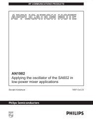
2.7 Terminal Assignments<br />
The <strong>TVP5150</strong> video decoder bridge is packaged in a 32-terminal PBS package. Figure 2−2 is the<br />
PBS-package terminal diagram. Table 2−1 gives a description of the terminals.<br />
4 SLES043A<br />
May 2006
Introduction<br />
TQFP PACKAGE<br />
(TOP VIEW)<br />
HSYNC<br />
AVID<br />
INTERQ/GPCL/VBLK<br />
PDN<br />
REFP<br />
REFM<br />
CH1_AGND<br />
CH1_AVDD<br />
24 23 22 21 20 19 18 17<br />
25<br />
26<br />
27<br />
28<br />
29<br />
30<br />
31<br />
32<br />
16<br />
15<br />
14<br />
13<br />
12<br />
11<br />
10<br />
9<br />
1 2 3 4 5 6 7 8<br />
YOUT2<br />
YOUT3<br />
YOUT4<br />
YOUT5<br />
YOUT6<br />
YOUT7/I2CSEL<br />
IO_DVDD<br />
SCLK<br />
AIP1A<br />
AIP1B<br />
PLL_AGND<br />
PLL_AVDD<br />
XTAL1/OSC<br />
XTAL2<br />
NSUB<br />
RESETB<br />
VSYNC/PALI<br />
FID/GLCO<br />
SDA<br />
SCL<br />
DVDD<br />
DGND<br />
YOUT0<br />
YOUT1<br />
Figure 2−2. <strong>TVP5150</strong> PBS-Package Terminal Diagram<br />
TERMINAL<br />
NAME NUMBER<br />
Analog Section<br />
AIP1A 1 I<br />
AIP1B 2 I<br />
CH1_AGND 31 I Analog ground<br />
Table 2−1. Terminal Functions<br />
I/O DESCRIPTION<br />
Analog input. Connect to the video analog input via 0.1-µF to 1-µF capacitor. The maximum input range is<br />
0−0.75 VPP, and may require an attenuator to reduce the input amplitude to the desired level. If not used,<br />
connect to AGND via 0.1-µF capacitor.<br />
Analog input. Connect to the video analog input via 0.1-µF to 1-µF capacitor. The maximum input range is<br />
0−0.75 VPP, and may require an attenuator to reduce the input amplitude to the desired level. If not used,<br />
connect to AGND via 0.1-µF capacitor.<br />
CH1_AVDD 32 I Analog supply. Connect to 1.8-V analog supply.<br />
NSUB 7 I Substrate. Connect to analog ground.<br />
PLL_AGND 3 I PLL ground. Connect to analog ground.<br />
PLL_AVDD 4 I PLL supply. Connect to 1.8-V analog supply.<br />
REFM 30 I<br />
A/D reference ground. Connect to analog ground through 1-µF capacitor. Also recommended to connect<br />
directly to REFP through 1-µF capacitor.<br />
REFP 29 I A/D reference supply. Connect to analog ground through 1-µF capacitor.<br />
May 2006<br />
SLES043A<br />
5
Introduction<br />
TERMINAL<br />
NAME NUMBER<br />
Digital Section<br />
AVID 26 O<br />
Table 2−1. Terminal Functions (Continued)<br />
I/O DESCRIPTION<br />
Active video indicator. This signal is high during the horizontal active time of the video output on the Y<br />
and UV terminals. AVID continues to toggle during vertical blanking intervals. This terminal can be<br />
placed in a high-impedance state.<br />
DGND 19 I Digital ground<br />
DVDD 20 I Digital supply. Connect to 1.8-V digital supply<br />
FID/GLCO 23 O<br />
FID: Odd/even field indicator or vertical lock indicator. For the odd/even indicator, a 1 indicates the odd<br />
field.<br />
GLCO: This serial output carries color PLL information. A slave device can decode the information to<br />
allow chroma frequency control from the <strong>TVP5150</strong> device. Data is transmitted at the SCLK rate in<br />
Genlock mode. In RTC mode, SCLK/4 is used.<br />
HSYNC 25 O Horizontal synchronization signal<br />
INTREQ/GPCL/<br />
VBLK<br />
27 I/O<br />
INTREQ: Interrupt request output.<br />
GPCL: General-purpose control logic. This terminal has three functions:<br />
1. General-purpose output. In this mode the state of GPCL is directly programmed via I2C.<br />
2. Vertical blank output. In this mode the GPCL terminal is used to indicate the vertical blanking interval<br />
of the output video. The beginning and end times of this signal are programmable via I2C.<br />
3. Sync lock control input. In this mode when GPCL is high, the output clock frequencies and the sync<br />
timing are forced to nominal values.<br />
IO_DVDD 10 I Digital supply. Connect to 3.3 V.<br />
PDN 28 I<br />
<strong>Power</strong>-down terminal (active low). Puts the device in standby mode. Preserves the value of the<br />
registers.<br />
RESETB 8 I<br />
Active-low reset. RESETB can be used only when PDN = 1.<br />
When RESETB is pulled low, it resets all the registers, restarts the internal microprocessor.<br />
SCL 21 I/O I2C serial clock (pullup to IO_DVDD <strong>with</strong> 1.2-kΩ resistor)<br />
SCLK 9 O System clock at either 1x or 2x the frequency of the pixel clock.<br />
SDA 22 I/O I2C serial data (pullup to IO_DVDD <strong>with</strong> 1.2-kΩ resistor)<br />
VSYNC/PALI 24 O<br />
XTAL1<br />
XTAL2<br />
YOUT[6:0]<br />
5<br />
6<br />
12, 13,<br />
14, 15,<br />
16, 17, 18<br />
I<br />
O<br />
I/O<br />
YOUT(7)/I2CSEL 11 I/O<br />
VSYNC: Vertical synchronization signal<br />
PALI: PAL line indicator or horizontal lock indicator<br />
For the PAL line indicator, a 1 indicates a noninverted line, and a 0 indicates an inverted line.<br />
External clock reference. The user may connect XTAL1 to an oscillator or to one terminal of a crystal<br />
oscillator. The user may connect XTAL2 to the other terminal of the crystal oscillator or not connect<br />
XTAL2 at all. One single 14.318-MHz crystal or oscillator is needed for ITU−R BT.601 sampling, for all<br />
supported standards.<br />
Output decoded ITU−R BT.656 output/YUV 422 output <strong>with</strong> discrete sync.<br />
I2CSEL: Determines address for I2C (sampled at startup). A pullup or pulldown register is needed<br />
(>1 kΩ) to program the terminal to the desired address.<br />
Logic 1: Address = 0xBA, Logic 0: Address = 0xB8<br />
YOUT7: MSB of output decoded ITU−R BT.656 output/YUV 422 output.<br />
6 SLES043A<br />
May 2006
3 Functional Description<br />
3.1 Input Multiplexers and Buffers<br />
Functional Description<br />
The <strong>TVP5150</strong> device has an analog input channel that accepts two video inputs, ac-coupled through 0.1-µF<br />
to 1-µF capacitors. The two analog input ports can be connected as follows:<br />
• Two selectable composite video inputs or<br />
• One S-video input<br />
The internal video multiplexers can be configured via I 2 C. The internal nodes are grounded for zero channel<br />
crosstalk. The input buffers are continuous time amplifiers that allow an input range of up to 0.75 V PP . This<br />
allows the decoder to support input ranges of 0 to 1.5 V <strong>with</strong> an external attenuation of one-half.<br />
3.2 Clamp<br />
An internal clamping circuit restores the ac-coupled video signal to a fixed dc level. The clamping circuit<br />
provides line-by-line restoration of the video sync level to a fixed dc reference voltage. Two modes of clamping<br />
are provided, coarse and fine.<br />
• In coarse mode, the most negative portion of the input signal (typically the sync tip) is clamped to a fixed<br />
dc level and remains on. This mode is used while the timing processor is searching for the horizontal sync.<br />
• Fine clamp mode is enabled after the horizontal lock is achieved. This is enabled to prevent spurious level<br />
shifting caused by noise more negative than the sync tip on the input signal. If fine clamp mode is selected,<br />
then clamping is only enabled during the sync period.<br />
− When in bottom level mode, the sync tip of the input signal is set to output code 0 of the A/D converter<br />
(ADC).<br />
− When in mid-level mode, fine clamp restores the dc level of the signal to the mid-range of the ADC.<br />
S-video requires the fine clamp mode on the chroma channel for proper operation. The clamp can be<br />
completely disabled using software registers.<br />
3.3 Programmable Gain Amplifier and Automatic Gain Control Circuit<br />
The programmable gain amplifier (PGA) and the automatic gain control (AGC) circuit work together to make<br />
sure that the input signal is amplified sufficiently to ensure the proper input range for the ADC. The gain is<br />
controlled by a 4-bit gain code.<br />
Input video signal amplitude can vary significantly from the nominal level of 1 V PP (140 IRE). An AGC circuit<br />
adjusts the signal amplitude to utilize the maximum range of the A/D converter <strong>with</strong>out clipping. The AGC<br />
adjusts the gain to achieve the desired sync amplitude. The PGA has a range of 0 to 12 dB.<br />
3.4 A/D Converter<br />
The ADC has 9 bits of resolution and runs at a maximum speed of 27 MHz. The clock input for the ADC comes<br />
from the PLL. The data is aligned to the pixel clock supplied from the PLL and matched in delay. The ADC uses<br />
the REFM and REFP terminals as the internal reference generator. For configuration of these terminals,<br />
please refer to Figure 5−1.<br />
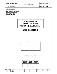
3.5 Composite Processing Block Diagram<br />
The composite processing block process NTSC/PAL signals into the YCbCr color space. Figure 3−1 explains<br />
the basic architecture of this processing block.<br />
Figure 3−1 illustrates the luminance/chrominance (Y/C) separation process in the <strong>TVP5150</strong> device. The<br />
composite video is multiplied by subcarrier signals in the quadrature modulator to generate color difference<br />
signals U and V. U and V are then low-pass filtered to achieve the desired bandwidth and to reduce crosstalk,<br />
by the color low-pass filters.<br />
May 2006<br />
SLES043A<br />
7
Functional Description<br />
An adaptive 4-line comb filter separates UV from Y based on the unique property of color phase shift from line<br />
to line. Chroma is remodulated through another quadrature modulator and subtracted from the line-delayed<br />
composite video to generate luma. This form of Y/C separation is completely complementary and thus loses<br />
no information. However, in some applications, it is desirable to limit the U/V bandwidth to avoid crosstalk. In<br />
that case, notch filters can be turned on. To accommodate some viewing preferences, a peaking filter is also<br />
available in the luma path. Contrast, brightness, hue, saturation, and sharpness are programmable via I 2 C.<br />
The Y/C separation is bypassed for S-video input. For S-video, the remodulation path is disabled. Since Y and<br />
C are already separated at the inputs, the only requirement is to digitize them and enable the same processing<br />
as the composite signal after Y/C separation.<br />
Gain Factor<br />
Peak<br />
Detector<br />
Bandpass<br />
X<br />
Peaking<br />
Composite<br />
Line<br />
Delay<br />
−<br />
Delay<br />
+<br />
Delay<br />
Y<br />
Y<br />
Quadrature<br />
Modulation<br />
Contrast<br />
Brightness<br />
Saturation<br />
Adjust<br />
U<br />
Notch<br />
Filter<br />
V<br />
Color<br />
LPF<br />
Notch<br />
Filter<br />
U<br />
V<br />
Composite<br />
Quadrature<br />
Demodulation<br />
U<br />
V<br />
Burst<br />
Accumulator<br />
(U)<br />
3- or 4-Line<br />
Adaptive<br />
Comb<br />
Filter<br />
Notch<br />
Filter<br />
Delay<br />
Color<br />
LPF<br />
Notch<br />
Filter<br />
Delay<br />
Burst<br />
Accumulator<br />
(V)<br />
3.6 Adaptive Comb Filtering<br />
Figure 3−1. Composite Processing Block Diagram<br />
Y/C separation can be performed using adaptive 4-line (3-H delay), fixed 3-line, fixed 2-line comb filters, or<br />
a chroma trap filter. Characteristics of 4-line and 3-line comb filters are shown in Figure 3−2.<br />
8 SLES043A<br />
May 2006
Functional Description<br />
The filter frequency plots show that both 4-line and 3-line (<strong>with</strong> filter coefficients [1,3,3,1]/8 and [1,2,1]/4) comb<br />
filters have zeros at 1/2 of the horizontal line frequency to separate the interleaved Y/C spectrum in NTSC.<br />
The 4-line comb filter has less cross-luma and cross-chroma noise due to slightly sharper filter cutoff. The<br />
4-line comb filter <strong>with</strong> filter coefficients [1,1,1,1]/4 has three zeros at 1/4, 2/4, and 3/4 of the horizontal line<br />
frequency. This is to be used for PAL only because of its 90 U/V phase shifting from line to line. The comb<br />
filter can be selectively bypassed in the luma or chroma path. If the comb filter is bypassed in the luma path,<br />
then chroma trap filters are used. TI’s patented adaptive comb filter algorithm reduces artifacts such as<br />
hanging dots at color boundaries and detects and properly handles false colors in high frequency luminance<br />
images such as a multiburst pattern or circle pattern. Adaptive comb filtering is the recommended mode of<br />
operation. The complete comb filter selection is shown in the chrominance control #1 register (see Section<br />
3.22.25).<br />
1.0<br />
0.8<br />
Amplitude − dB<br />
0.6<br />
0.4<br />
0.2<br />
3 line (1,2,1)/4<br />
4 line (1,3,3,1)/8<br />
4 line (1,1,1,1)/4<br />
0.0<br />
0 1 2 3 4 5<br />
f − Frequency − MHz<br />
Figure 3−2. Comb Filters Frequency Response<br />
May 2006<br />
SLES043A<br />
9
Functional Description<br />
10<br />
10<br />
5<br />
Notch3 Filter<br />
5<br />
Notch3 Filter<br />
0<br />
0<br />
−5<br />
−5<br />
Amplitude − dB<br />
−10<br />
−15<br />
−20<br />
−25<br />
Notch1 Filter<br />
Notch2 Filter<br />
Amplitude − dB<br />
−10<br />
−15<br />
−20<br />
−25<br />
Notch1 Filter<br />
Notch2 Filter<br />
−30<br />
No Notch Filter<br />
−30<br />
No Notch Filter<br />
−35<br />
−35<br />
−40<br />
0 1 2 3 4 5 6 7<br />
f − Frequency − MHz<br />
Figure 3−3. Chroma Trap Filter Frequency<br />
Response, NTSC ITU−R BT.601 Sampling<br />
−40<br />
0 1 2 3 4 5 6 7<br />
f − Frequency − MHz<br />
Figure 3−4. Chroma Trap Filter Frequency<br />
Response, PAL ITU−R BT.601 Sampling<br />
3.7 Color <strong>Low</strong>-Pass Filter<br />
In some applications, it is desirable to limit the U/V bandwidth to avoid crosstalk. This is especially true in case<br />
of nonstandard video signals that have asymmetrical U/V sidebands. In this case, notch filters are provided<br />
that limit the bandwidth of the U/V signals.<br />
Notch filters are needed when the comb filtering turns off, due to extreme color transitions in the input image.<br />
The response of these notch filters is shown in Figure 3−5. The notch filters have three options that allow three<br />
different frequency responses based on the color frequency characteristics of the input video.<br />
Amplitude − dB<br />
10<br />
0<br />
−10<br />
−20<br />
−30<br />
−40<br />
Notch2 Filter<br />
−3 dB @ 844 kHz<br />
No Notch Filter<br />
−3 dB @ 1.412 MHz<br />
Notch3 Filter<br />
−3 dB @ 554 kHz<br />
Notch1<br />
Filter −3 dB<br />
@ 1.03 MHz<br />
−50<br />
−60<br />
−70<br />
0.0 0.5 1.0 1.5 2.0 2.5 3.0 3.5 4.0<br />
f − Frequency − MHz<br />
Figure 3−5. Color <strong>Low</strong>-Pass Filter With Notch Filter Characteristics, NTSC/PAL ITU−R BT.601 Sampling<br />
10 SLES043A<br />
May 2006
Functional Description<br />
3.8 Luminance Processing<br />
The luma component is derived from the composite signal by subtracting the remodulated chroma information.<br />
A line delay exists in this path to compensate for the line delay in the adaptive comb filter in the color processing<br />
chain. The luma information is then fed into the peaking circuit, which enhances the high frequency<br />
components of the signal as shown in Figure 3−6.<br />
7<br />
6<br />
5<br />
Peak at<br />
f = 2.40 MHz<br />
Gain = 2<br />
Amplitude − dB<br />
4<br />
3<br />
2<br />
Gain = 1<br />
Gain = 0.5<br />
1<br />
0<br />
Gain = 0<br />
−1<br />
0 1 2 3 4 5 6 7<br />
f − Frequency − MHz<br />
Figure 3−6. Peaking Filter Response, NTSC/PAL ITU−R BT.601 Sampling<br />
3.9 Chrominance Processing<br />
For PAL/NTSC formats, the color processing begins <strong>with</strong> a quadrature demodulator extracting U and V<br />
components from the composite signal. The U/V signals then pass through the gain control stage for chroma<br />
saturation adjustment. An adaptive comb filter is applied to both U and V to eliminate cross-chrominance<br />
noise. Hue control is achieved <strong>with</strong> phase shift of the digitally controlled oscillator. An automatic color killer<br />
circuit is also included in this block. The color killer suppresses the chroma processing when the color burst<br />
of the video signal is weak or not present.<br />
3.10 Timing Processor<br />
The timing processor is a combination of hardware and software running in the internal microprocessor that<br />
serves to control horizontal lock to the input sync pulse edge, AGC and offset adjustment in the analog front<br />
end, vertical sync detection, and Macrovision detection.<br />
3.11 VBI Data Processor<br />
The <strong>TVP5150</strong> VBI data processor (VDP) slices various data services like Teletext (WST, NABTS), Closed<br />
Caption (CC), wide screen signaling (WSS), etc. These services are acquired by programming the VDP to<br />
enable a standard(s) in the vertical blank interval. The results are stored in a FIFO and/or registers. The<br />
Teletext results are stored in a FIFO only. Listed in Table 3−1 is a summary of the types of vertical blank interval<br />
data supported according to the video standard. It supports ITU−R BT. 601 sampling for each. Thirteen<br />
standard modes are currently supported.<br />
May 2006<br />
SLES043A<br />
11
Functional Description<br />
LINE MODE<br />
REGISTER (D0h−FCh)<br />
BITS [3:0]<br />
SAMPLING<br />
RATE (0Dh)<br />
BIT 7<br />
Table 3−1. Data Types Supported by the VDP<br />
NAME<br />
DESCRIPTION<br />
0000b x x Reserved<br />
0000b x x Reserved<br />
0001b x x Reserved<br />
0001b 1 WST PAL B 6 Teletext, PAL, System B, ITU−R BT.601<br />
0010b x x Reserved<br />
0010b 1 WST PAL C 6 Teletext, PAL, System C, ITU−R BT.601<br />
0011b x x Reserved<br />
0011b 1 WST, NTSC B 6 Teletext, NTSC, System B, ITU−R BT.601<br />
0100b x x Reserved<br />
0100b 1 NABTS, NTSC C 6 Teletext, NTSC, System C, ITU−R BT.601<br />
0101b x x Reserved<br />
0101b 1 NABTS, NTSC D 6 Teletext, NTSC, System D (Japan), ITU−R BT.601<br />
0110b x x Reserved<br />
0110b 1 CC, PAL 6 Closed caption PAL, ITU−R BT.601<br />
0111b x x Reserved<br />
0111b 1 CC, NTSC 6 Closed caption NTSC, ITU−R BT.601<br />
1000b x x Reserved<br />
1000b 1 WSS, PAL 6 Wide-screen signal, PAL, ITU−R BT.601<br />
1001b x x Reserved<br />
1001b 1 WSS, NTSC 6 Wide-screen signal, NTSC, ITU−R BT.601<br />
1010b x x Reserved<br />
1010b 1 VITC, PAL 6 Vertical interval timecode, PAL, ITU−R BT.601<br />
1011b x x Reserved<br />
1011b 1 VITC, NTSC 6 Vertical interval timecode, NTSC, ITU−R BT.601<br />
1100b x x Reserved<br />
1100b 1 VPS, PAL 6 <strong>Video</strong> program system, PAL, ITU−R BT.601<br />
1101b x x Reserved<br />
1110b x x Reserved<br />
1111b x Active <strong>Video</strong> Active video/full field<br />
At powerup the host interface is required to program the VDP-configuration RAM (VDP-CRAM) contents <strong>with</strong><br />
the lookup table (see Section 3.22.54). This is done through port address C3h. Each read from or write to this<br />
address will auto increment an internal counter to the next RAM location. To access the VDP-CRAM, the line<br />
mode registers (D0h−FCh) must be programmed <strong>with</strong> FFh to avoid a conflict <strong>with</strong> the internal microprocessor<br />
and the VDP in both writing and reading. Full field mode must also be disabled.<br />
Available VBI lines are from line 6 to line 27 of both field 1 and field 2. Each line can be any VBI mode. When<br />
changing modes, the VDP must allow the current transaction to complete through the delays of the VDP before<br />
switching the line mode register contents. It must also complete loading of the line mode registers before the<br />
next line starts processing. The switch pixel number is set through registers CBh and CCh (see Section<br />
3.22.60).<br />
Output data is available either through the VBI-FIFO (B0h) or through dedicated registers at 90h−AFh, both<br />
of which are available through the I 2 C port.<br />
12 SLES043A<br />
May 2006
Functional Description<br />
3.12 VBI FIFO and Ancillary Data in <strong>Video</strong> Stream<br />
BYTE<br />
NO.<br />
Sliced VBI data can be output as ancillary data in the video stream in the ITU−R BT.656 mode. VBI data is<br />
output during the horizontal blanking period following the line from which the data was retrieved. Table 3−2<br />
shows the header format and sequence of the ancillary data inserted into the video stream. This format is also<br />
used to store any VBI data into the FIFO. The size of FIFO is 512 bytes. Therefore, the FIFO can store up to<br />
11 lines of teletext data <strong>with</strong> the NTSC NABTS standard.<br />
Table 3−2. Ancillary Data Format and Sequence<br />
D7<br />
(MSB)<br />
D6 D5 D4 D3 D2 D1 D0<br />
(LSB)<br />
DESCRIPTION<br />
0 0 0 0 0 0 0 0 0 Ancillary data preamble<br />
1 1 1 1 1 1 1 1 1<br />
2 1 1 1 1 1 1 1 1<br />
3 NEP EP 0 1 0 DID2 DID1 DID0 Data ID (DID)<br />
4 NEP EP F5 F4 F3 F2 F1 F0 Secondary data ID (SDID)<br />
5 NEP EP N5 N4 N3 N2 N1 N0 Number of 32 bit data (NN)<br />
6 <strong>Video</strong> line # [7:0] Internal Data ID0 (IDID0)<br />
7 0 0 0 Data Match Match <strong>Video</strong> line # [9:8] Internal Data ID1 (IDID1)<br />
error #1 #2<br />
8 1. Data Data byte 1st word<br />
9 2. Data Data byte<br />
10 3. Data Data byte<br />
11 4. Data Data byte<br />
: : :<br />
m−1. Data Data byte Nth word<br />
m. Data Data byte<br />
NEP EP CS[5:0] Check sum<br />
4(N+2) 1 0 0 0 0 0 0 0 Fill byte<br />
EP: Even parity for D0−D5 NEP: Negated even parity<br />
DID:<br />
SDID:<br />
NN:<br />
91h: Sliced data of VBI lines of first field<br />
53h: Sliced data of line 24 to end of first field<br />
55h: Sliced data of VBI lines of second field<br />
97h: Sliced data of line 24 to end of second field<br />
This field holds the data format taken from the line mode register of the corresponding line.<br />
Number of Dwords beginning <strong>with</strong> byte 8 through 4(N+2). This value is the number of Dwords<br />
where each Dword is 4 bytes.<br />
IDID0: Transaction video line number [7:0]<br />
IDID1: Bit 0/1 = Transaction video line number [9:8]<br />
Bit 2 = Match 2 flag<br />
Bit 3 = Match 1 flag<br />
Bit 4 = 1 if an error was detected in the EDC block. 0 if not.<br />
CS:<br />
Fill byte:<br />
Sum of D0−D7 of DID through last data byte.<br />
Fill bytes make a multiple of 4 bytes from byte 0 to last fill byte. For teletext modes, byte 8 is the<br />
sync pattern byte. Byte 9 is 1. Data (the first data byte).<br />
May 2006<br />
SLES043A<br />
13
Functional Description<br />
3.13 Raw <strong>Video</strong> Data Output<br />
The <strong>TVP5150</strong> device can output raw A/D video data at 2x sampling rate for external VBI slicing. This is<br />
transmitted as an ancillary data block during the active horizontal portion of the line and during vertical<br />
blanking.<br />
3.14 Output Formatter<br />
The YUV digital output can be programmed as 8-bit 4:2:2 or 8-bit ITU−R BT.656 parallel interface standard.<br />
Table 3−3. Summary of Line Frequencies, Data Rates, and Pixel Counts<br />
STANDARDS<br />
HORIZONTAL<br />
LINE RATE (kHz)<br />
PIXELS PER<br />
LINE<br />
ACTIVE PIXELS<br />
PER LINE<br />
SCLK FREQUENCY<br />
(MHz)<br />
NTSC (M, 4.43), ITU−R BT.601 15.73426 858 720 27.00<br />
PAL (B, D, G, H, I), ITU−R BT.601 15.625 864 720 27.00<br />
Y0<br />
U0<br />
V0<br />
Y1<br />
Y2<br />
U1<br />
V1<br />
Y3<br />
Y4<br />
U2<br />
V2<br />
Y5<br />
Y716<br />
U358<br />
V358<br />
Y717<br />
Y718<br />
U359<br />
V359<br />
Y719<br />
= Luminance-Only Sample<br />
= Luminance and Chrominance Sample<br />
Timing is for 13.5-MHz sampling<br />
Figure 3−7. 4:2:2 Sampling<br />
The different formats that are supported and the corresponding sampling frequencies are listed as follows:<br />
MODES<br />
DATA CLOCK<br />
FREQUENCY<br />
TERMINALS<br />
8-bit ITU−R BT.601 SCLK Y(7−0) YCbCr<br />
8-bit 4:2:2 SCLK Y(7−0) YCbCr<br />
The following diagram explains the different modes.<br />
EMBEDDED SYNCS,<br />
VBI DATA, RAW DATA<br />
Syncs optional<br />
VBI optional (edge prog)<br />
Raw data optional<br />
Syncs optional<br />
VBI optional (edge prog)<br />
Raw data optional<br />
STANDARDS<br />
SUPPORTED<br />
NTSC/PAL<br />
YUV output<br />
Any standard<br />
YUV output<br />
SCLK<br />
YOUT[7:0] U0 Y0 V0 Y1 U1 Y2 U359 Y718 V359 Y719<br />
Numbering shown is for 13.5-MHz sampling<br />
Figure 3−8. 8-Bit YCbCr 4:2:2 and ITU−R BT.656 Mode Timing<br />
14 SLES043A<br />
May 2006
Functional Description<br />
3.15 Synchronization Signals<br />
Nondata stream embedded syncs are provided via the following signals:<br />
• VSYNC (vertical sync)<br />
• FID/VLK (field indicator or vertical lock indicator)<br />
• GPCL/VBLK (general-purpose I/O or vertical blanking indicator)<br />
• PALI/HLK (PAL switch indicator or horizontal lock indicator)<br />
• HSYNC (horizontal sync)<br />
• AVID (active video indicator)<br />
In hardware, VSYNC, FID, PALI, and VBLK are software-set and programmable to the SCLK pixel count. This<br />
allows any possible alignment to the internal pixel count and line count. The proper settings for a 525-/625-line<br />
video output are given as an example below.<br />
May 2006<br />
SLES043A<br />
15
Functional Description<br />
Composite<br />
<strong>Video</strong><br />
VSYNC<br />
525<br />
525-Line<br />
1 2 3 4 5 6 7 8 9 10 11 20 21 22<br />
FID<br />
GPCL/VBLK<br />
− ← 0 → +<br />
VBLK Start<br />
− ← 0 → +<br />
VBLK Stop<br />
Composite<br />
<strong>Video</strong><br />
262 263 264 265 266 267 268 269 270 271 272 273 282 283 284<br />
VSYNC<br />
FID<br />
GPCL/VBLK<br />
− ← 0 → +<br />
VBLK Start<br />
− ← 0 → +<br />
VBLK Stop<br />
Composite<br />
<strong>Video</strong><br />
625-Line<br />
310 311 312 313 314 315 316 317 318 319 320 333 334 335 336<br />
VSYNC<br />
FID<br />
GPCL/VBLK<br />
− ← 0 → +<br />
VBLK Start<br />
− ← 0 → +<br />
VBLK Stop<br />
Composite<br />
<strong>Video</strong><br />
622 623 624 625 1 2 3 4 5 6 7 20 21 22 23<br />
VSYNC<br />
FID<br />
GPCL/VBLK<br />
− ← 0 → +<br />
VBLK Start<br />
− ← 0 → +<br />
VBLK Stop<br />
Notes:<br />
1. Line numbering conforms to ITU−R BT.470<br />
Figure 3−9. 8-bit 4:2:2, Timing With 2x Pixel Clock (SCLK) Reference<br />
16 SLES043A<br />
May 2006
Functional Description<br />
ITU−R BT.656 timing shown <strong>with</strong>out embedded syncs.<br />
NTSC 601 1436<br />
1437<br />
1438<br />
1439<br />
1440<br />
1441<br />
…<br />
1455<br />
1456<br />
…<br />
1583<br />
1584<br />
…<br />
1711<br />
1712<br />
1713<br />
1714<br />
1715<br />
0<br />
1<br />
2<br />
3<br />
PAL 601 1436<br />
1437<br />
1438<br />
1439<br />
1440<br />
1441<br />
…<br />
1459<br />
1460<br />
…<br />
1587<br />
1588<br />
…<br />
1723<br />
1724<br />
1725<br />
1726<br />
1727<br />
0<br />
1<br />
2<br />
3<br />
ITU 656<br />
Datastream<br />
Cb<br />
359<br />
Y<br />
718<br />
Cr<br />
359<br />
Y<br />
719<br />
FF<br />
00<br />
…<br />
10<br />
80<br />
…<br />
10<br />
80<br />
…<br />
10<br />
FF<br />
00<br />
00<br />
XX<br />
Cb<br />
0<br />
Y<br />
0<br />
Cr<br />
0<br />
Y<br />
1<br />
HSYNC<br />
AVID<br />
− ← 0 → +<br />
HSYNC Start<br />
− ← 0 → +<br />
AVID Stop<br />
− ← 0 → +<br />
AVID Start<br />
NOTE: AVID rising edge occurs 4 SCLK cycles early when in ITU−R BT.656 output<br />
mode.<br />
3.16 AVID Cropping<br />
Figure 3−10. Horizontal Synchronization Signals<br />
AVID or active video cropping provides a means to decrease bandwidth of the video output. This is<br />
accomplished by horizontally blanking a number of AVID pulses and by vertically blanking a number of lines<br />
per frame. The horizontal AVID cropping is controlled using registers 11h and 12h for start pixels MSB and<br />
LSB, respectively.<br />
Registers 13h and 14h provide access to stop pixels MSB and LSB, respectively. The vertical AVID cropping<br />
is controlled using the vertical blanking (VBLK) start and stop registers at addresses 18h and 19h. Figure 3−11<br />
shows an AVID application.<br />
May 2006<br />
SLES043A<br />
17
Functional Description<br />
VBLK Stop<br />
Active <strong>Video</strong> Area<br />
AVID Cropped<br />
Area<br />
VSYNC<br />
VBLK Start<br />
HSYNC<br />
AVID Start<br />
AVID Stop<br />
3.17 Embedded Syncs<br />
Figure 3−11. AVID Application<br />
Standards <strong>with</strong> embedded syncs insert SAV and EAV codes into the datastream on the rising and falling edges<br />
of AVID. These codes contain the V and F bits which also define vertical timing. F and V are software<br />
programmable and change after SAV but before EAV, so that the new value always appears on EAV first.<br />
Table 3−4 gives the format of the SAV and EAV codes.<br />
H equals 1 always indicates EAV. H equals 0 always indicates SAV. The alignment of V and F to the line and<br />
field counter varies depending on the standard.<br />
The P bits are protection bits:<br />
P3 = V xor H<br />
P2 = F xor H<br />
P1 = F xor V<br />
P0 = F xor V xor H<br />
Table 3−4. EAV and SAV Sequence<br />
8-BIT DATA<br />
D7 (MSB) D6 D5 D4 D3 D2 D1 D0<br />
Preamble 1 1 1 1 1 1 1 1<br />
Preamble 0 0 0 0 0 0 0 0<br />
Preamble 0 0 0 0 0 0 0 0<br />
Status word 1 F V H P3 P2 P1 P0<br />
18 SLES043A<br />
May 2006
3.18 I 2 C Host Interface<br />
Functional Description<br />
The I 2 C standard consists of two signals, serial input/output data line (SDA) and input/output clock line (SCL),<br />
which carry information between the devices connected to the bus. A third signal (I2CSEL) is used for slave<br />
address selection. Although the I 2 C system can be multimastered, the <strong>TVP5150</strong> device functions as a slave<br />
device only.<br />
Both SDA and SCL must be connected to a positive supply voltage via a pullup resistor. When the bus is free,<br />
both lines are high. The slave address select terminal (I2CSEL) enables the use of two <strong>TVP5150</strong> devices tied<br />
to the same I 2 C bus. At power up, the status of the I2CSEL is polled. Depending on the write and read<br />
addresses to be used for the <strong>TVP5150</strong> device, it can either pulled low or high through a resistor. This terminal<br />
is multiplexed <strong>with</strong> YOUT7 and hence must not be tied directly to ground or V DD . Table 3−6 summarizes the<br />
terminal functions of the I 2 C-mode host interface.<br />
Table 3−5. Write Address Selection<br />
I2CSEL WRITE ADDRESS<br />
0 B8h<br />
1 BAh<br />
Table 3−6. I 2 C Terminal Description<br />
SIGNAL TYPE DESCRIPTION<br />
I2CSEL (YOUT7) I Slave address selection<br />
SCL I/O (open drain) Input/output clock line<br />
SDA I/O (open drain) Input/output data line<br />
Data transfer rate on the bus is up to 400 kbits/s. The number of interfaces connected to the bus is dependent<br />
on the bus capacitance limit of 400 pF. The data on the SDA line must be stable during the high period of the<br />
SCL except for start and stop conditions. The high or low state of the data line can only change <strong>with</strong> the clock<br />
signal on the SCL line being low. A high-to-low transition on the SDA line while the SCL is high indicates an<br />
I 2 C start condition. A low-to-high transition on the SDA line while the SCL is high indicates an I 2 C stop<br />
condition.<br />
Every byte placed on the SDA must be 8 bits long. The number of bytes which can be transferred is<br />
unrestricted. Each byte must be followed by an acknowledge bit. The acknowledge-related clock pulse is<br />
generated by the I 2 C master.<br />
3.18.1 I 2 C Write Operation<br />
Data transfers occur utilizing the following illustrated formats.<br />
An I 2 C master initiates a write operation to the <strong>TVP5150</strong> device by generating a start condition (S) followed<br />
by the <strong>TVP5150</strong> I 2 C address (as shown below), in MSB first bit order, followed by a 0 to indicate a write cycle.<br />
After receiving an acknowledge from the <strong>TVP5150</strong> device, the master presents the subaddress of the register,<br />
or the first of a block of registers it wants to write, followed by one or more bytes of data, MSB first. The<br />
<strong>TVP5150</strong> device acknowledges each byte after completion of each transfer. The I 2 C master terminates the<br />
write operation by generating a stop condition (P).<br />
Step 1 0<br />
I2C Start (master)<br />
S<br />
Step 2 7 6 5 4 3 2 1 0<br />
I2C General address (master) 1 0 1 1 1 0 X 0<br />
Step 3 9<br />
I2C Acknowledge (slave)<br />
A<br />
May 2006<br />
SLES043A<br />
19
Functional Description<br />
Step 4 7 6 5 4 3 2 1 0<br />
I2C Write register address (master) addr addr addr addr addr addr addr addr<br />
Step 5 9<br />
I2C Acknowledge (slave)<br />
A<br />
Step 6 7 6 5 4 3 2 1 0<br />
I2C Write data (master) Data Data Data Data Data Data Data Data<br />
Step 7† 9<br />
I2C Acknowledge (slave)<br />
Step 8 0<br />
I2C Stop (master)<br />
P<br />
† Repeat steps 6 and 7 until all data have been written.<br />
3.18.2 I 2 C Read Operation<br />
A<br />
The read operation consists of two phases. The first phase is the address phase. In this phase, an I 2 C master<br />
initiates a write operation to the <strong>TVP5150</strong> device by generating a start condition (S) followed by the <strong>TVP5150</strong><br />
I 2 C address, in MSB first bit order, followed by a 0 to indicate a write cycle. After receiving acknowledges from<br />
the <strong>TVP5150</strong> device, the master presents the subaddress of the register or the first of a block of registers it<br />
wants to read. After the cycle is acknowledged, the master terminates the cycle immediately by generating<br />
a stop condition (P).<br />
Table 3−7. Read Address Selection<br />
I2CSEL READ ADDRESS<br />
0 B9h<br />
1 BBh<br />
The second phase is the data phase. In this phase, an I 2 C master initiates a read operation to the <strong>TVP5150</strong><br />
device by generating a start condition followed by the <strong>TVP5150</strong> I 2 C address (as shown below for a read<br />
operation), in MSB first bit order, followed by a 1 to indicate a read cycle. After an acknowledge from the<br />
<strong>TVP5150</strong> device, the I 2 C master receives one or more bytes of data from the <strong>TVP5150</strong> device. The I 2 C master<br />
acknowledges the transfer at the end of each byte. After the last data byte desired has been transferred from<br />
the <strong>TVP5150</strong> device to the master, the master generates a not acknowledge followed by a stop.<br />
3.18.2.1 Read Phase 1<br />
Step 1 0<br />
I2C Start (master)<br />
S<br />
Step 2 7 6 5 4 3 2 1 0<br />
I2C General address (master) 1 0 1 1 1 0 X 0<br />
Step 3 9<br />
I2C Acknowledge (slave)<br />
A<br />
Step 4 7 6 5 4 3 2 1 0<br />
I2C Read register address (master) addr addr addr addr addr addr addr addr<br />
Step 5 9<br />
I2C Acknowledge (slave)<br />
A<br />
20 SLES043A<br />
May 2006
Functional Description<br />
Step 6 0<br />
I2C Stop (master)<br />
P<br />
3.18.2.2 Read Phase 2<br />
Step 7 0<br />
I2C Start (master)<br />
S<br />
Step 8 7 6 5 4 3 2 1 0<br />
I2C General address (master) 1 0 1 1 1 0 X 1<br />
Step 9 9<br />
I2C Acknowledge (slave)<br />
A<br />
Step 10 7 6 5 4 3 2 1 0<br />
I2C Read data (slave) Data Data Data Data Data Data Data Data<br />
Step 11† 9<br />
I2C Not Acknowledge (master)<br />
A<br />
Step 12 0<br />
I2C Stop (master)<br />
P<br />
† Repeat steps 10 and 11 for all bytes read. Master does not acknowledge the last read data received.<br />
3.18.2.3 I 2 C Timing Requirements<br />
The <strong>TVP5150</strong> device requires delays in the I 2 C accesses to accommodate its internal processor’s timing. In<br />
accordance <strong>with</strong> I 2 C specifications, the <strong>TVP5150</strong> device holds the I 2 C clock line (SCL) low to indicate the wait<br />
period to the I 2 C master. If the I 2 C master is not designed to check for the I 2 C clock line held-low condition,<br />
then the maximum delays must always be inserted where required. These delays are of variable length;<br />
maximum delays are indicated in the following diagram:<br />
Normal register writing address 00h−8Fh (addresses 90h−FFh do not require delays)<br />
Start<br />
Slave address<br />
(B8h)<br />
Ack Subaddress Ack<br />
Data<br />
(XXh)<br />
Ack Wait 64 µs Stop<br />
3.19 Clock Circuits<br />
An internal line-locked phase-locked loop (PLL) generates the system and pixel clocks. The PLL minimizes<br />
jitter and process and environmental variability. It is capable of operating off a single crystal frequency <strong>with</strong><br />
a high supply rejection ratio. A 14.318-MHz clock is required to drive the PLL. This may be input to the<br />
<strong>TVP5150</strong> device on terminal 5 (XTAL1), or a crystal of 14.318-MHz fundamental resonant frequency may be<br />
connected across terminals 5 and 6 (XTAL2). Figure 3−12 shows the reference clock configurations. For the<br />
example crystal circuit shown (a parallel-resonant crystal <strong>with</strong> 14.318-MHz fundamental frequency), the<br />
external capacitors must have the following relationship:<br />
C L1 = C L2 = 2C L − C STRAY ,<br />
where C STRAY is the terminal capacitance <strong>with</strong> respect to ground. Please note that <strong>with</strong> the crystal oscillator,<br />
an external 100-kΩ resistor can be optionally put across XTAL1 and XTAL2 terminals. Figure 3−12 shows the<br />
reference clock configurations.<br />
May 2006<br />
SLES043A<br />
21
Functional Description<br />
<strong>TVP5150</strong><br />
<strong>TVP5150</strong><br />
14.318-MHz or<br />
27-MHz Crystal<br />
XTAL1<br />
XTAL2<br />
5<br />
6<br />
14.318-MHz or<br />
27-MHz Clock<br />
XTAL1<br />
XTAL2<br />
5<br />
6<br />
R<br />
CL1<br />
CL2<br />
NOTE: 100-kΩ resistor R is optional<br />
Figure 3−12. Reference Clock Configurations<br />
3.20 Genlock Control (GLCO) and Real-Time Control (RTC)<br />
A Genlock control function is provided to support a standard video encoder to synchronize its internal color<br />
phase DCO for a clean video line and color lock.<br />
The frequency control word of the internal color subcarrier digital control oscillator (DCO) and the subcarrier<br />
phase reset bit are transmitted via terminal 23 (GLCO). The frequency control word is a 23-bit binary number.<br />
The frequency of the DCO can be calculated from the following equation:<br />
F<br />
F<br />
2<br />
ctrl<br />
dco<br />
= 23<br />
x<br />
where F dco is the frequency of the DCO, F ctrl is the 23-bit DCO frequency control, and F sclk is the frequency<br />
of the SCLK.<br />
3.20.1 <strong>TVP5150</strong> Genlock Control Interface<br />
A write of 1 to bit 4 of the chrominance control register at I 2 C subaddress 1Ah causes the subcarrier DTO<br />
phase reset bit to be sent on the next scan line on GLCO. The active low reset bit occurs 7 SCLKs after the<br />
transmission of the last bit of DCO frequency control. Upon the transmission of the reset bit, the phase of the<br />
<strong>TVP5150</strong> internal subcarrier DCO is reset to zero.<br />
A Genlock slave device can be connected to the GLCO terminal and use the information on GLCO to<br />
synchronize its internal color phase DCO to achieve clean line and color lock.<br />
Figure 3−13 shows the timing diagram of the GLCO mode.<br />
F<br />
sclk<br />
SCLK<br />
GLCO<br />
MSB<br />
LSB<br />
>128 SCLK<br />
22 21 0<br />
23 SCLK<br />
23-Bit Frequency Control<br />
1 SCLK<br />
7 SCLK<br />
1 SCLK<br />
Start Bit<br />
DCO Reset Bit<br />
Figure 3−13. GLCO Timing<br />
22 SLES043A<br />
May 2006
Functional Description<br />
3.20.2 RTC Mode<br />
Figure 3−14 shows the timing diagram of the RTC mode. Clock rate for the RTC mode is 4 times slower than<br />
the GLCO clock rate. For PLL frequency control, the upper 22 bits are used. Each frequency control bit is 2<br />
clock cycles long. The active low reset bit occurs 6 CLKs after the transmission of the last bit of PLL frequency<br />
control.<br />
RTC<br />
M<br />
S<br />
B<br />
21 0<br />
L<br />
S<br />
B<br />
128 CLK<br />
Start<br />
Bit<br />
16 CLK<br />
2 CLK<br />
44 CLK<br />
22-Bit Fsc Frequency Control<br />
2 CLK<br />
3 CLK<br />
1 CLK<br />
PAL<br />
Switch<br />
3.21 Internal Control Registers<br />
Figure 3−14. RTC Timing<br />
The <strong>TVP5150</strong> device is initialized and controlled by a set of internal registers which set all device operating<br />
parameters. Communication between the external controller and the <strong>TVP5150</strong> device is through I 2 C.<br />
Table 3−8 shows the summary of these registers. The reserved registers must not be written. However,<br />
reserved bits in the defined registers must be written <strong>with</strong> 0s. The detailed programming information of each<br />
register is described in the following sections.<br />
Table 3−8. Registers Summary<br />
REGISTER FUNCTION ADDRESS DEFAULT R/W<br />
<strong>Video</strong> input source selection #1 00h 00h R/W<br />
Analog channel controls 01h 15h R/W<br />
Operation mode controls 02h 00h R/W<br />
Miscellaneous controls 03h 01h R/W<br />
Autoswitch mask 04h 00h R/W<br />
Software reset 05h 00h R/W<br />
Color killer threshold control 06h 10h R/W<br />
Luminance processing control #1 07h 20h R/W<br />
Luminance processing control #2 08h 00h R/W<br />
Brightness control 09h 80h R/W<br />
Color saturation control 0Ah 80h R/W<br />
Hue control 0Bh 00h R/W<br />
Contrast control 0Ch 80h R/W<br />
Outputs and data rates select 0Dh 47h R/W<br />
R = Read only<br />
W = Write only<br />
R/W = Read and write<br />
1 CLK<br />
Reset<br />
Bit<br />
May 2006<br />
SLES043A<br />
23
Functional Description<br />
Table 3−8. Registers Summary (Continued)<br />
REGISTER FUNCTION ADDRESS DEFAULT R/W<br />
Luminance processing control #3 0Eh 00h R/W<br />
Configuration shared pins 0Fh 08h R/W<br />
Reserved<br />
Active video cropping start MSB 11h 00h R/W<br />
Active video cropping start LSB 12h 00h R/W<br />
Active video cropping stop MSB 13h 00h R/W<br />
Active video cropping stop LSB 14h 00h R/W<br />
Genlock/RTC 15h 01h R/W<br />
Horizontal sync start 16h 80h R/W<br />
Reserved<br />
Vertical blanking start 18h 00h R/W<br />
Vertical blanking stop 19h 00h R/W<br />
Chrominance processing control #1 1Ah 0Ch R/W<br />
Chrominance processing control #2 1Bh 14h R/W<br />
Interrupt reset register B 1Ch 00h R/W<br />
Interrupt enable register B 1Dh 00h R/W<br />
Interrupt configuration register B 1Eh 00h R/W<br />
Reserved<br />
10h<br />
17h<br />
1Fh−27h<br />
<strong>Video</strong> standard 28h 00h R/W<br />
Reserved<br />
29h–7Fh<br />
MSB of device ID 80h 51h R<br />
LSB of device ID 81h 50h R<br />
ROM version 82h 02h R<br />
RAM patch-code version 83h 10h R<br />
Vertical line count MSB 84h R<br />
Vertical line count LSB 85h R<br />
Interrupt status register B 86h R<br />
Interrupt active register B 87h 00h R<br />
Status register #1 88h R<br />
Status register #2 89h R<br />
Status register #3 8Ah R<br />
Status register #4 8Bh R<br />
Status register #5 8Ch R<br />
Reserved<br />
8Dh−8Fh<br />
Closed caption data registers 90h−93h R<br />
WSS data registers 94h−99h R<br />
VPS data registers 9Ah−A6h R<br />
VITC data registers A7h−AFh R<br />
VBI FIFO read data B0h R<br />
Teletext filter 1 B1h−B5h 00h R/W<br />
Teletext filter 2 B6h−BAh 00h R/W<br />
R = Read only<br />
W = Write only<br />
R/W = Read and write<br />
24 SLES043A<br />
May 2006
Functional Description<br />
Table 3−8. Registers Summary (Continued)<br />
REGISTER FUNCTION ADDRESS DEFAULT R/W<br />
Teletext filter enable BBh 00h R/W<br />
Reserved<br />
BCh−BFh<br />
Interrupt status register A C0h 00h R/W<br />
Interrupt enable register A C1h 00h R/W<br />
Interrupt configuration C2h 04h R/W<br />
VDP configuration RAM data C3h DCh R/W<br />
Configuration RAM address low byte C4h 0Fh R/W<br />
Configuration RAM address high byte C5h 00h R/W<br />
VDP status register C6h R/W<br />
FIFO word count C7h R<br />
FIFO interrupt threshold C8h 80h R/W<br />
FIFO reset C9h 00h W<br />
Line number interrupt CAh 00h R/W<br />
Pixel alignment register low byte CBh 59h R/W<br />
Pixel alignment register high byte CCh 03h R/W<br />
FIFO output control CDh 01h R/W<br />
Automatic initialization CEh 00h R/W<br />
Full field enable CFh 00h R/W<br />
Line mode registers D0h−FBh FFh R/W<br />
Full field mode register FCh 7Fh R/W<br />
Reserved<br />
R = Read only<br />
W = Write only<br />
R/W = Read and write<br />
3.22 Register Definitions<br />
3.22.1 <strong>Video</strong> Input Source Selection #1 Register<br />
Address<br />
00h<br />
FDh−FFh<br />
7 6 5 4 3 2 1 0<br />
Channel 1 source<br />
Reserved<br />
S-video selection<br />
selection<br />
Channel 1 source selection:<br />
0 = AIP1A selected (default)<br />
1 = AIP1B selected<br />
Table 3−9. Analog Channel and <strong>Video</strong> Mode Selection<br />
ADDRESS 00<br />
INPUT(S) SELECTED<br />
BIT 1 BIT 0<br />
Composite AIP1A (default) 0 0<br />
AIP1B 1 0<br />
S-<strong>Video</strong> 1A luma, 2A chroma x 1<br />
May 2006<br />
SLES043A<br />
25
Functional Description<br />
3.22.2 Analog Channel Controls Register<br />
Address<br />
01h<br />
7 6 5 4 3 2 1 0<br />
Reserved 1 Automatic offset control Automatic gain control<br />
Automatic offset control:<br />
00 = Disabled<br />
01 = Automatic offset enabled (default)<br />
10 = Reserved<br />
11 = Clamping level frozen to the previously set value<br />
Automatic gain control (AGC):<br />
00 = Disabled (fixed gain value)<br />
01 = AGC enabled (default)<br />
10 = Reserved<br />
11 = AGC frozen to the previously set value<br />
3.22.3 Operation Mode Controls Register<br />
Address<br />
02h<br />
7 6 5 4 3 2 1 0<br />
Reserved Color subcarrier PLL frozen Reserved <strong>Power</strong> down mode<br />
Color subcarrier PLL frozen:<br />
0 = Color subcarrier PLL increments by the internally generated phase increment. (default)<br />
GLCO pin outputs the frequency increment.<br />
1 = Color subcarrier PLL stops operating.<br />
GLCO pin outputs the frozen frequency increment.<br />
<strong>Power</strong> down mode:<br />
0 = Normal operation (default)<br />
1 = <strong>Power</strong> down mode. A/Ds are turned off and internal clocks are reduced to minimum.<br />
3.22.4 Miscellaneous Control Register<br />
Address<br />
03h<br />
7 6 5 4 3 2 1 0<br />
VBKO<br />
GPCL pin<br />
GPCL I/O mode<br />
select<br />
VBKO (pin 27) function select:<br />
0 = GPCL (default)<br />
1 = VBLK<br />
Lock status<br />
(HVLK)<br />
GPCL (data is output based on state of bit 5):<br />
0 = GPCL outputs 0 (default)<br />
1 = GPCL outputs 1<br />
GPCL I/O mode select:<br />
0 = GPCL is input (default)<br />
1 = GPCL is output<br />
YUV output<br />
enable (TVPOE)<br />
HSYNC, VSYNC/PALI,<br />
AVID, FID/GLCO<br />
output enable<br />
Vertical blanking<br />
on/off<br />
Clock output<br />
enable<br />
26 SLES043A<br />
May 2006
Functional Description<br />
Lock status (HVLK) (configured along <strong>with</strong> register 0Fh):<br />
0 = Terminal VSYNC/PALI outputs. PAL indicator (PALI) signal and terminal FID/GLCO outputs field ID<br />
(FID) signal (default) (if terminals are configured to output PALI and FID in register 0Fh)<br />
1 = Terminal VSYNC/PALI outputs horizontal lock indicator (HLK) and terminal FID outputs vertical lock<br />
indicator (VLK) (if terminals are configured to output PALI and FID in register 0Fh)<br />
These are additional functionalities that are provided for ease of use.<br />
YUV output enable:<br />
0 = Y(OUT7:0) high impedance (default)<br />
1 = Y(OUT7:0) active<br />
HSYNC, VSYNC/PALI, active video indicator (AVID), and FID/GLCO output enables:<br />
0 = HSYNC, VSYNC/PALI, AVID, and FID/GLCO are high-impedance (default).<br />
1 = HSYNC, VSYNC/PALI, AVID, and FID/GLCO are active.<br />
Vertical blanking on/off:<br />
0 = Vertical blanking (VBLK) off (default)<br />
1 = Vertical blanking (VBLK) on<br />
Clock output enable:<br />
0 = SCLK output is high impedance.<br />
1 = SCLK output is enabled (default).<br />
Table 3−10. Digital Output Control<br />
Terminal 28<br />
(AVID)<br />
Register 03h,<br />
Bit 3 (TVPOE)<br />
Register C2h,<br />
Bit 2 (VDPOE)<br />
1 during reset X X<br />
0 during reset X X<br />
YUV Output<br />
Active after<br />
reset<br />
High impedance<br />
after reset<br />
Notes<br />
After reset and before YUV output enable bits are programmed.<br />
TVPOE defaults to 1 and VDPOE is 1.<br />
After reset and before YUV output enable bits are programmed.<br />
TVPOE defaults to 0 and VDPOE is 1.<br />
X 0 X High impedance After both YUV output enable bits are programmed.<br />
X X 0 High impedance After both YUV output enable bits are programmed.<br />
X 1 1 Active After both YUV output enable bits are programmed.<br />
3.22.5 Autoswitch Mask Register<br />
Address<br />
04h<br />
7 6 5 4 3 2 1 0<br />
Reserved N443_OFF PALN_OFF PALM_OFF Reserved<br />
N443_OFF:<br />
0 = NTSC443 is masked from the autoswitch process. Autoswitch does not switch to NTSC443.<br />
1 = Normal operation (default)<br />
PALN_OFF:<br />
0 = PAL-N is masked from the autoswitch process. Autoswitch does not switch to PAL-N.<br />
1 = Normal operation (default)<br />
PALM_OFF:<br />
0 = PAL-M is masked from the autoswitch process. Autoswitch does not switch to PAL-M.<br />
1 = Normal operation (default)<br />
May 2006<br />
SLES043A<br />
27
Functional Description<br />
3.22.6 Software Reset Register<br />
Address<br />
05h<br />
7 6 5 4 3 2 1 0<br />
Reset:<br />
0 = Normal operation (default)<br />
1 = Reset device<br />
Reserved<br />
3.22.7 Color Killer Threshold Control Register<br />
Address<br />
06h<br />
7 6 5 4 3 2 1 0<br />
Reserved Automatic color killer Color killer threshold<br />
Automatic color killer:<br />
00 = Automatic mode (default)<br />
01 = Reserved<br />
10 = Color killer enabled, the UV terminals are forced to a zero color state.<br />
11 = Color killer disabled<br />
Color killer threshold:<br />
11111 = −30 dB (minimum)<br />
10000 = −24 dB (default)<br />
00000 = −18 dB (maximum)<br />
3.22.8 Luminance Processing Control #1 Register<br />
Address<br />
07h<br />
7 6 5 4 3 2 1 0<br />
Luma bypass mode<br />
Pedestal not present<br />
Disable raw<br />
header<br />
Luma bypass during<br />
vertical blank<br />
Reset<br />
Luminance signal delay <strong>with</strong> respect to<br />
chrominance signal<br />
Luma bypass mode:<br />
0 = Input video bypasses the chroma trap and comb filters. Chroma outputs are forced to zero (default).<br />
1 = Input video bypasses the whole luma processing. Raw A/D data is output alternatively as UV data and<br />
Y data at SCLK rate. The output data is properly clipped to comply to ITU−R BT.601 coding range. Only<br />
valid for 8-bit YUV output format (YUV output format = 100 or 111 at register 0Dh).<br />
Pedestal not present:<br />
0 = 7.5 IRE pedestal is present on the analog video input signal (default).<br />
1 = Pedestal is not present on the analog video input signal.<br />
Disable raw header:<br />
0 = Insert 656 ancillary headers for raw data.<br />
1 = Disable 656 ancillary headers and instead force dummy ones (0x40) (default).<br />
Luminance bypass enabled during vertical blanking:<br />
0 = Disabled (default)<br />
1 = Enabled<br />
Luminance bypass occurs for the duration of the vertical blanking as defined by registers 18h and 19h. This<br />
feature may be used to prevent distortion of test and data signals present during the vertical blanking interval.<br />
28 SLES043A<br />
May 2006
Functional Description<br />
Luma signal delay <strong>with</strong> respect to chroma signal in pixel clock increments (range −8 to +7 pixel clocks):<br />
1111 = −8 pixel clocks delay<br />
1011 = −4 pixel clocks delay<br />
1000 = −1 pixel clocks delay<br />
0000 = 0 pixel clocks delay (default)<br />
0011 = 3 pixel clocks delay<br />
0111 = 7 pixel clocks delay<br />
3.22.9 Luminance Processing Control #2 Register<br />
Address<br />
08h<br />
7 6 5 4 3 2 1 0<br />
Reserved Luminance filter select Reserved Peaking gain Reserved<br />
Luminance filter select:<br />
0 = Luminance comb filter enabled (default)<br />
1 = Luminance chroma trap filter enabled<br />
Peaking gain:<br />
00 = 0 (default)<br />
01 = 0.5<br />
10 = 1<br />
11 = 2<br />
Information on peaking frequency: ITU−R BT.601 sampling rate: all standards—2.6 MHz<br />
3.22.10 Brightness Control Register<br />
Address<br />
09h<br />
7 6 5 4 3 2 1 0<br />
Brightness control<br />
Brightness control:<br />
1111 1111 = 255 (bright)<br />
1000 1011 = 139 (ITU−R BT.601 level)<br />
1000 0000 = 128 (default)<br />
0000 0000 = 0 (dark)<br />
3.22.11 Color Saturation Control Register<br />
Address<br />
0Ah<br />
7 6 5 4 3 2 1 0<br />
Saturation control<br />
Saturation control:<br />
1111 1111 = 255 (maximum)<br />
1000 0000 = 128 (default)<br />
0000 0000 = 0 (no color)<br />
May 2006<br />
SLES043A<br />
29
Functional Description<br />
3.22.12 Hue Control Register<br />
Address<br />
0Bh<br />
7 6 5 4 3 2 1 0<br />
Hue control:<br />
0111 1111 = +180 degrees<br />
0000 0000 = 0 degrees (default)<br />
1000 0000 = −180 degrees<br />
3.22.13 Contrast Control Register<br />
Address<br />
0Ch<br />
Hue control<br />
7 6 5 4 3 2 1 0<br />
Contrast control<br />
Contrast control:<br />
1111 1111 = 255 (maximum contrast)<br />
1000 0000 = 128 (default)<br />
0000 0000 = 0 (minimum contrast)<br />
3.22.14 Outputs and Data Rates Select Register<br />
Address<br />
0Dh<br />
7 6 5 4 3 2 1 0<br />
Reserved YUV output code range UV code format YUV data path bypass YUV output format<br />
YUV output code range:<br />
0 = ITU−R BT.601 coding range (Y ranges from 16 to 235. U and V range from 16 to 240)<br />
1 = Extended coding range (Y, U, and V range from 1 to 254) (default)<br />
UV code format:<br />
0 = Offset binary code (2s complement + 128) (default)<br />
1 = Straight binary code (2s complement)<br />
YUV data path bypass:<br />
00 = Normal operation (default)<br />
01 = Digital composite output pins connected to decimation filter output, decoder function bypassed,<br />
data output alternately as Y and UV buses at the SCLK rate.<br />
10 = YUV output pins connected to A/D output, decoder function bypassed, data output at SCLK rate.<br />
11 = Reserved<br />
YUV output format:<br />
000 = 8-bit 4:2:2 YUV <strong>with</strong> discrete sync output<br />
001 = Reserved<br />
010 = Reserved<br />
011 = Reserved<br />
100 = Reserved<br />
101 = Reserved<br />
110 = Reserved<br />
111 = 8-bit ITU−R BT.656 interface <strong>with</strong> embedded sync output (default)<br />
30 SLES043A<br />
May 2006
Functional Description<br />
3.22.15 Luminance Processing Control #3 Register<br />
Address<br />
0Eh<br />
7 6 5 4 3 2 1 0<br />
Reserved<br />
Luminance filter stop band bandwidth (MHz):<br />
00 = No notch (default)<br />
01 = Notch 1<br />
10 = Notch 2<br />
11 = Notch 3<br />
Luminance trap filter select<br />
Luminance filter select [1:0] selects one of the four chroma trap filters to produce luminance signal by removing<br />
the chrominance signal from the composite video signal. The stopband of the chroma trap filter is centered<br />
at the chroma subcarrier frequency <strong>with</strong> stopband bandwidth controlled by the two control bits. Please refer<br />
to Figure 3−5, for the frequency responses of the filters.<br />
3.22.16 Configuration Shared Pins<br />
Address<br />
0Fh<br />
7 6 5 4 3 2 1 0<br />
Reserved LOCK23 LOCK24A LOCK24B FID/GLCO VSYNC/PALI INTREQ/GPCL/VBLK SCLK/PCLK<br />
LOCK23 (pin 23) function select:<br />
0 = FID (default, if bit 3 is selected to output FID)<br />
1 = Lock indicator (Indicates whether device is locked both horizontally and vertically)<br />
LOCK24A (pin 24) function select:<br />
0 = VSYNC (default, if bit 2 is selected to output VSYNC)<br />
1 = Lock indicator (Indicates whether device is locked both horizontally and vertically)<br />
LOCK24B (pin 24) function select:<br />
0 = PALI (default, if bit 2 is selected to output PALI)<br />
1 = Lock indicator (Indicates whether device is locked both horizontally and vertically)<br />
FID/GLCO (pin 23) function select (also refer to register 03h for enhanced functionality):<br />
0 = FID<br />
1 = GLCO (default)<br />
VSYNC/PALI (pin 24) function select (also refer to register 03h for enhanced functionality):<br />
0 = VSYNC (default)<br />
1 = PALI<br />
INTREQ/GPCL/VBLK (pin 27) function select:<br />
0 = INTREQ (default)<br />
1 = GPCL or VBLK depending on bit 7 of register 03h<br />
SCLK/PCLK (pin 9) function select:<br />
0 = SCLK (default)<br />
1 = PCLK (1x pixel clock frequency)<br />
May 2006<br />
SLES043A<br />
31
Functional Description<br />
3.22.17 Active <strong>Video</strong> Cropping Start Pixel MSB<br />
Address<br />
11h<br />
7 6 5 4 3 2 1 0<br />
AVIDST_MSB [9:2]<br />
Active video cropping start pixel MSB [9:2], set this register first before setting register 12h. The <strong>TVP5150</strong><br />
device updates the AVID start values only when register 12h is written to.<br />
3.22.18 Active <strong>Video</strong> Cropping Start Pixel LSB<br />
Address<br />
12h<br />
7 6 5 4 3 2 1 0<br />
Reserved AVID active AVIDST_LSB [1:0]<br />
AVID active:<br />
0 = AVID out active in VBLK (default)<br />
1 = AVID out inactive in VBLK<br />
Active video cropping start pixel LSB [1:0]: The <strong>TVP5150</strong> device updates the AVID start values only when this<br />
register is written to.<br />
AVID start [9:0] (combined registers 11h and 12h):<br />
01 1111 1111 = 511<br />
00 0000 0001 = 1<br />
00 0000 0000 = 0 (default)<br />
11 1111 1111 = −1<br />
10 0000 0000 = −512<br />
3.22.19 Active <strong>Video</strong> Cropping Stop Pixel MSB<br />
Address<br />
13h<br />
7 6 5 4 3 2 1 0<br />
AVID stop pixel MSB<br />
Active video cropping stop pixel MSB [9:2], set this register first before setting the register 14h. The <strong>TVP5150</strong><br />
device updates the AVID stop values only when register 14h is written to.<br />
3.22.20 Active <strong>Video</strong> Cropping Stop Pixel LSB<br />
Address<br />
14h<br />
7 6 5 4 3 2 1 0<br />
Reserved<br />
AVID stop pixel LSB<br />
Active video cropping stop pixel LSB [1:0]: The number of pixels of active video must be an even number. The<br />
<strong>TVP5150</strong> device updates the AVID stop values only when this register is written to.<br />
AVID stop [9:0] (combined registers 13h and 14h):<br />
01 1111 1111 = 511<br />
00 0000 0001 = 1<br />
00 0000 0000 = 0 (default) (see Figure 3−10)<br />
11 1111 1111 = −1<br />
10 0000 0000 = −512<br />
32 SLES043A<br />
May 2006
Functional Description<br />
3.22.21 Genlock and RTC Register<br />
Address<br />
15h<br />
7 6 5 4 3 2 1 0<br />
Reserved CDTO_SW Reserved GLCO/ RTC<br />
CDTO_LSB_Switch (CDTO_SW):<br />
0 = CDTO_LSB is forced to 0<br />
1 = CDTO_LSB is forced to 1 (default)<br />
GLCO/RTC:<br />
0 = GLCO output<br />
1 = RTC output (default)<br />
Figure 3−13 shows the timing of GLCO and Figure 3−14 shows the timing of RTC.<br />
3.22.22 Horizontal Sync (HSYNC) Start Register<br />
Address 16h<br />
7 6 5 4 3 2 1 0<br />
HSYNC start<br />
HSYNC start:<br />
1111 1111 = −127 x 4 pixel clocks<br />
1111 1110 = −126 x 4 pixel clocks<br />
1111 1101 = −125 x 4 pixel clocks<br />
1000 0000 = 0 pixel clocks (default)<br />
0111 1111 = 1 x 4 pixel clocks<br />
0111 1110 = 2 x 4 pixel clocks<br />
0000 0000 = 128 x 4 pixel clocks<br />
BT.656 EAV Code<br />
BT.656 SAV Code<br />
YOUT<br />
[7:0]<br />
U<br />
Y V Y 0<br />
F<br />
F<br />
0<br />
0<br />
0<br />
0<br />
0<br />
0<br />
X<br />
Y<br />
Z<br />
0<br />
8<br />
0<br />
0<br />
1<br />
0<br />
0<br />
8<br />
0<br />
0<br />
1<br />
0<br />
0<br />
F<br />
F<br />
0<br />
0<br />
0<br />
0<br />
0<br />
0<br />
X<br />
Y<br />
Z<br />
U<br />
Y<br />
HSYNC<br />
AVID<br />
Start of<br />
Digital Line<br />
Nhbhs<br />
Nhb<br />
128 SCLK<br />
Start of Digital<br />
Active Line<br />
Figure 3−15. Horizontal Sync<br />
Table 3−11. Clock Delays (SCLKs)<br />
STANDARD Nhbhs Nhb<br />
NTSC 601 32 272<br />
PAL 601 24 284<br />
May 2006<br />
SLES043A<br />
33
Functional Description<br />
Detailed timing information is also available in Section 3.15, Synchronization Signals.<br />
3.22.23 Vertical Blanking Start Register<br />
Address<br />
18h<br />
7 6 5 4 3 2 1 0<br />
Vertical blanking start<br />
Vertical blanking (VBLK) start:<br />
0111 1111 = 127 lines after start of vertical blanking interval<br />
0000 0001 = 1 line after start of vertical blanking interval<br />
0000 0000 = Same time as start of vertical blanking interval (default) (see Figure 3−9)<br />
1000 0001 = 1 line before start of vertical blanking interval<br />
1111 1111 = 128 lines before start of vertical blanking interval<br />
Vertical blanking is adjustable <strong>with</strong> respect to the standard vertical blanking intervals. The setting in this<br />
register determines the timing of the GPCL/VBLK signal when it is configured to output vertical blank (see<br />
register 03h). The setting in this register also determines the duration of the luma bypass function (see register<br />
07h).<br />
3.22.24 Vertical Blanking Stop Register<br />
Address<br />
19h<br />
7 6 5 4 3 2 1 0<br />
Vertical blanking stop<br />
Vertical blanking (VBLK) stop:<br />
0111 1111 = 127 lines after stop of vertical blanking interval<br />
0000 0001 = 1 line after stop of vertical blanking interval<br />
0000 0000 = Same time as stop of vertical blanking interval (default) (see Figure 3−9)<br />
1000 0001 = 1 line before stop of vertical blanking interval<br />
1111 1111 = 128 lines before stop of vertical blanking interval<br />
Vertical blanking is adjustable <strong>with</strong> respect to the standard vertical blanking intervals. The setting in this<br />
register determines the timing of the GPCL/VBLK signal when it is configured to output vertical blank (see<br />
register 03h). The setting in this register also determines the duration of the luma bypass function (see register<br />
07h).<br />
3.22.25 Chrominance Control #1 Register<br />
Address<br />
1Ah<br />
7 6 5 4 3 2 1 0<br />
Reserved<br />
Color PLL reset<br />
Color PLL reset:<br />
0 = Color PLL not reset (default)<br />
1 = Color PLL reset<br />
Chrominance adaptive<br />
comb filter enable (ACE)<br />
Chrominance comb filter<br />
enable (CE)<br />
Automatic color gain control<br />
Color PLL phase is reset to zero and the color PLL reset bit then immediately returns to zero. When this bit<br />
is set, the subcarrier PLL phase reset bit is transmitted on terminal 23 (GLCO) on the next line (NTSC or PAL).<br />
Chrominance adaptive comb filter enable (ACE):<br />
34 SLES043A<br />
May 2006
Functional Description<br />
0 = Disable<br />
1 = Enable (default)<br />
Chrominance comb filter enable (CE):<br />
0 = Disable<br />
1 = Enable (default)<br />
Automatic color gain control (ACGC):<br />
00 = ACGC enabled (default)<br />
01 = Reserved<br />
10 = ACGC disabled<br />
11 = ACGC frozen to the previously set value<br />
3.22.26 Chrominance Control #2 Register<br />
Address<br />
1Bh<br />
7 6 5 4 3 2 1 0<br />
Chrominance comb filter mode [3:0] Reserved WCF Chrominance filter select<br />
Chrominance comb filter mode [3:0] (CM[3:0]): Chrominance control #2 register 1Bh, bits 7−4<br />
ACE CE CM[3] CM[2] CM[1] CM[0] COMB FILTER SELECTION<br />
0 0 X X X X Comb filter disabled<br />
0 1 0 0 0 X Fixed 3-line comb filter <strong>with</strong> (1, 2, 1)/4 coefficients<br />
0 1 0 0 1 X Fixed 3-line comb filter <strong>with</strong> (1, 0, 1)/2 coefficients<br />
0 1 1 0 X X Fixed 2-line comb filter<br />
0 1 0 1 0 X Fixed 4-line (1, 1, 1, 1)/4 comb filter<br />
0 1 0 1 1 X Fixed 4-line (1, 3, 3, 1)/8 comb filter<br />
0 1 1 1 X X Fixed 2-line comb filter<br />
1 X X 0 0 0 Adaptive between 3-line (1, 2, 1)/4 and 2-line comb filter<br />
1† X X 0† 0† 1† Adaptive between 3-line (1, 2, 1)/4 comb filter and no comb filter<br />
1 X X 0 1 0 Adaptive between 3-line (1, 0, 1)/2 comb filter and 2-line comb filter<br />
1 X X 0 1 1 Adaptive between 3-line (1, 0, 1)/2 comb filter and no comb filter<br />
1 X X 1 0 0 Adaptive between 4-line (1, 1, 1, 1)/4 and 2-line comb filter<br />
1‡ X X 1‡ 0‡ 1‡ Adaptive between 4-line (1, 1, 1, 1)/4 comb filter and no comb filter<br />
1 X X 1 1 0 Adaptive between 4-line (1, 3, 3, 1)/8 comb filter and 2-line comb filter<br />
1 X X 1 1 1 Adaptive between 4-line (1, 3, 3, 1)/8 comb filter and no comb filter<br />
† Indicates default settings for NTSC<br />
‡ Indicates default settings for PAL mode<br />
Wideband chroma filter (WCF):<br />
0 = Disable<br />
1 = Enable (default)<br />
Chrominance filter select:<br />
00 = No notch (default)<br />
01 = Notch 1<br />
10 = Notch 2<br />
11 = Notch 3<br />
May 2006<br />
SLES043A<br />
35
Functional Description<br />
Chrominance output bandwidth (MHz):<br />
WCF FILTER SELECT NTSC ITU−R BT.601 PAL ITU−R BT.601<br />
0<br />
1<br />
00 1.2214 1.2214<br />
01 0.8782 0.8782<br />
10 0.7297 0.7297<br />
11 0.4986 0.4986<br />
00 1.4170 1.4170<br />
01 1.0303 1.0303<br />
10 0.8438 0.8438<br />
11 0.5537 0.5537<br />
3.22.27 Interrupt Reset Register B<br />
Address<br />
1Ch<br />
7 6 5 4 3 2 1 0<br />
Software<br />
initialization<br />
reset<br />
Macrovision<br />
detect changed<br />
reset<br />
Command<br />
ready reset<br />
Software initialization reset:<br />
0 = No effect (default)<br />
1 = Reset software initialization bit<br />
Field rate<br />
changed reset<br />
Macrovision detect changed reset:<br />
0 = No effect (default)<br />
1 = Reset macrovision detect changed bit<br />
Command ready reset:<br />
0 = No effect (default)<br />
1 = Reset command ready bit<br />
Field rate changed reset:<br />
0 = No effect (default)<br />
1 = Reset field rate changed bit<br />
Line alternation changed reset:<br />
0 = No effect (default)<br />
1 = Reset line alternation changed bit<br />
Color lock changed reset:<br />
0 = No effect (default)<br />
1 = Reset color lock changed bit<br />
H/V lock changed reset:<br />
0 = No effect (default)<br />
1 = Reset H/V lock changed bit<br />
Line alternation<br />
changed reset<br />
Color lock<br />
changed reset<br />
H/V lock<br />
changed reset<br />
TV/VCR<br />
changed reset<br />
TV/VCR changed reset [TV/VCR mode is determined by counting the total number of lines/frame. The mode<br />
switches to VCR for nonstandard number of lines]:<br />
0 = No effect (default)<br />
1 = Reset TV/VCR changed bit<br />
36 SLES043A<br />
May 2006
Functional Description<br />
Interrupt reset register B is used by the external processor to reset the interrupt status bits in interrupt status<br />
register B. Bits loaded <strong>with</strong> a 1 allow the corresponding interrupt status bit to reset to 0. Bits loaded <strong>with</strong> a 0<br />
have no effect on the interrupt status bits.<br />
3.22.28 Interrupt Enable Register B<br />
Address<br />
1Dh<br />
7 6 5 4 3 2 1 0<br />
Software initialization<br />
occurred enable<br />
Macrovision<br />
detect changed<br />
Command<br />
ready enable<br />
Software initialization occurred enable:<br />
0 = Disabled (default)<br />
1 = Enabled<br />
Macrovision detect changed:<br />
0 = Disabled (default)<br />
1 = Enabled<br />
Command ready enable:<br />
0 = Disabled (default)<br />
1 = Enabled<br />
Field rate changed:<br />
0 = Disabled (default)<br />
1 = Enabled<br />
Line alternation changed:<br />
0 = Disabled (default)<br />
1 = Enabled<br />
Color lock changed:<br />
0 = Disabled (default)<br />
1 = Enabled<br />
H/V lock changed:<br />
0 = Disabled (default)<br />
1 = Enabled<br />
TV/VCR changed:<br />
0 = Disabled (default)<br />
1 = Enabled<br />
Field rate<br />
changed<br />
Line alternation<br />
changed<br />
Color lock<br />
changed<br />
H/V lock<br />
changed<br />
TV/VCR<br />
changed<br />
Interrupt enable register B is used by the external processor to mask unnecessary interrupt sources for<br />
interrupt B. Bits loaded <strong>with</strong> a 1 allow the corresponding interrupt condition to generate an interrupt on the<br />
external pin. Conversely, bits loaded <strong>with</strong> a 0 mask the corresponding interrupt condition from generating an<br />
interrupt on the external pin. This register only affects the external pin, it does not affect the bits in the interrupt<br />
status register. A given condition can set the appropriate bit in the status register and not cause an interrupt<br />
on the external pin. To determine if this device is driving the interrupt pin either AND interrupt status register<br />
B <strong>with</strong> interrupt enable register B or check the state of interrupt B in the interrupt B active register.<br />
May 2006<br />
SLES043A<br />
37
Functional Description<br />
3.22.29 Interrupt Configuration Register B<br />
Address<br />
1Eh<br />
7 6 5 4 3 2 1 0<br />
Reserved<br />
Interrupt polarity B<br />
Interrupt polarity B:<br />
0 = Interrupt B is active low (default).<br />
1 = Interrupt B is active high.<br />
Interrupt polarity B must be same as interrupt polarity A bit at bit 0 of the interrupt configuration register A at<br />
address C2h.<br />
Interrupt configuration register B is used to configure the polarity of interrupt B on the external interrupt pin.<br />
When the interrupt B is configured for active low, the pin is driven low when active and high-impedance when<br />
inactive (open-collector). Conversely, when the interrupt B is configured for active high, it is driven<br />
high-impedance for active and driven low for inactive.<br />
3.22.30 <strong>Video</strong> Standard Register<br />
Address<br />
28h<br />
7 6 5 4 3 2 1 0<br />
Reserved<br />
<strong>Video</strong> standard<br />
<strong>Video</strong> standard:<br />
0000 = Autoswitch mode (default)<br />
0001 = Reserved<br />
0010 = (M) NTSC ITU−R BT.601<br />
0011 = Reserved<br />
0100 = (B, G, H, I, N) PAL ITU−R BT.601<br />
0101 = Reserved<br />
0110 = (M) PAL ITU−R BT.601<br />
0111 = Reserved<br />
1000 = (Combination-N) ITU−R BT.601<br />
1001 = Reserved<br />
1010 = NTSC 4.43 ITU−R BT.601<br />
1011 = Reserved<br />
1100 = Reserved<br />
With the autoswitch code running, the user can force the device to operate in a particular video standard mode<br />
and sample rate by writing the appropriate value into this register.<br />
3.22.31 MSB of Device ID Register<br />
Address<br />
80h<br />
7 6 5 4 3 2 1 0<br />
MSB of device ID<br />
This register identifies the MSB of the device ID. Value = 0x51.<br />
3.22.32 LSB of Device ID Register<br />
Address<br />
81h<br />
7 6 5 4 3 2 1 0<br />
LSB of device ID<br />
This register identifies the LSB of the device ID. Value = 0x50.<br />
38 SLES043A<br />
May 2006
Functional Description<br />
3.22.33 ROM Version Register<br />
Address<br />
82h<br />
7 6 5 4 3 2 1 0<br />
Value = 0x02<br />
3.22.34 RAM Patch Code Version Register<br />
Address<br />
83h<br />
ROM version: 0x01 for 1.0, 0x20 for 2.00<br />
7 6 5 4 3 2 1 0<br />
Value = 0x10<br />
RAM patch code version: 0x10 for combined version 2-1, 0x20 for combined version 2-2<br />
3.22.35 Vertical Line Count MSB Register<br />
Address<br />
84h<br />
7 6 5 4 3 2 1 0<br />
Vertical line count bits [9:8]<br />
Reserved<br />
3.22.36 Vertical Line Count LSB Register<br />
Address<br />
85h<br />
Vertical line count MSB<br />
7 6 5 4 3 2 1 0<br />
Vertical line count bits [7:0]<br />
Vertical line count LSB<br />
Registers 84h and 85h can be read and combined to extract the current vertical line count. This can be used<br />
<strong>with</strong> nonstandard video signals such as a VCR in fast-forward or rewind modes to synchronize the<br />
downstream video circuitry.<br />
3.22.37 Interrupt Status Register B<br />
Address<br />
86h<br />
7 6 5 4 3 2 1 0<br />
Software<br />
initialization<br />
Macrovision detect<br />
changed<br />
Reserved<br />
Field rate<br />
changed<br />
Software initialization:<br />
0 = Software initialization is not ready (default).<br />
1 = Software initialization is ready.<br />
Line alternation<br />
changed<br />
Macrovision detect changed:<br />
0 = Macrovision detect status has not changed (default).<br />
1 = Macrovision detect status has changed.<br />
Field rate changed:<br />
0 = Field rate has not changed (default).<br />
1 = Field rate has changed.<br />
Color lock<br />
changed<br />
H/V lock<br />
changed<br />
TV/VCR<br />
changed<br />
May 2006<br />
SLES043A<br />
39
Functional Description<br />
Line alternation changed:<br />
0 = Line alteration has not changed (default).<br />
1 = Line alternation has changed.<br />
Color lock changed:<br />
0 = Color lock status has not changed (default).<br />
1 = Color lock status has changed.<br />
H/V lock changed:<br />
0 = H/V lock status has not changed (default).<br />
1 = H/V lock status has changed.<br />
TV/VCR changed:<br />
0 = TV/VCR status has not changed (default).<br />
1 = TV/VCR status has changed.<br />
Interrupt status register B is polled by the external processor to determine the interrupt source for interrupt<br />
B. After an interrupt condition is set, it can be reset by writing to the interrupt reset register B at subaddress<br />
1Ch <strong>with</strong> a 1 in the appropriate bit.<br />
3.22.38 Interrupt Active Register B<br />
Address<br />
87h<br />
7 6 5 4 3 2 1 0<br />
Reserved<br />
Interrupt B<br />
Interrupt B:<br />
0 = Interrupt B is not active on the external terminal (default).<br />
1 = Interrupt B is active on the external terminal.<br />
The interrupt active register B is polled by the external processor to determine if interrupt B is active.<br />
3.22.39 Status Register #1<br />
Address<br />
88h<br />
7 6 5 4 3 2 1 0<br />
Peak white<br />
detect status<br />
Line-alternating<br />
status<br />
Field rate<br />
status<br />
Peak white detect status:<br />
0 = Peak white is not detected.<br />
1 = Peak white is detected.<br />
Line-alternating status:<br />
0 = Nonline alternating<br />
1 = Line alternating<br />
Field rate status:<br />
0 = 60 Hz<br />
1 = 50 Hz<br />
Lost lock detect:<br />
Lost lock<br />
detect<br />
Color subcarrier<br />
lock status<br />
Vertical sync<br />
lock status<br />
Horizontal sync<br />
lock status<br />
TV/VCR status<br />
40 SLES043A<br />
May 2006
Functional Description<br />
0 = No lost lock since status register #1 was last read.<br />
1 = Lost lock since status register #1 was last read.<br />
Color subcarrier lock status:<br />
0 = Color subcarrier is not locked.<br />
1 = Color subcarrier is locked.<br />
Vertical sync lock status:<br />
0 = Vertical sync is not locked.<br />
1 = Vertical sync is locked.<br />
Horizontal sync lock status:<br />
0 = Horizontal sync is not locked.<br />
1 = Horizontal sync is locked.<br />
TV/VCR status [TV/VCR mode is determined by counting the total number of lines/frame. The mode switches<br />
to VCR for nonstandard number of lines]:<br />
0 = TV<br />
1 = VCR<br />
3.22.40 Status Register #2<br />
Address<br />
89h<br />
7 6 5 4 3 2 1 0<br />
Reserved<br />
Weak signal<br />
detection<br />
PAL switch<br />
polarity<br />
Field sequence<br />
status<br />
AGC and offset frozen<br />
status<br />
Reserved<br />
Macrovision detection<br />
Weak signal detection:<br />
0 = No weak signal<br />
1 = Weak signal mode<br />
PAL switch polarity of first line of odd field:<br />
0 = PAL switch is 0<br />
1 = PAL switch is 1<br />
Field sequence status:<br />
0 = Even field<br />
1 = Odd field<br />
AGC and offset frozen status:<br />
0 = AGC and offset are not frozen.<br />
1 = AGC and offset are frozen.<br />
Macrovision detection:<br />
00 = No copy protection<br />
01 = AGC pulses/pseudo-syncs present<br />
10 = AGC pulses/pseudo-syncs and 2-line color striping present<br />
11 = AGC pulses/pseudo-syncs and 4-line color striping present<br />
May 2006<br />
SLES043A<br />
41
Functional Description<br />
3.22.41 Status Register #3<br />
Address<br />
AGC gain:<br />
8Ah<br />
7 6 5 4 3 2 1 0<br />
0000 0000 = −6 dB<br />
0100 0000 = −3 dB<br />
1000 0000 = 0 dB<br />
1100 0000 = 3 dB<br />
1111 1111 = 6 dB<br />
3.22.42 Status Register #4<br />
Address<br />
8Bh<br />
AGC gain<br />
7 6 5 4 3 2 1 0<br />
Subcarrier to horizontal (SCH) phase<br />
SCH (color PLL subcarrier phase at 50% of the falling edge of horizontal sync of line one of odd field; step<br />
size 360/256):<br />
0000 0000 = 0.00<br />
0000 0001 = 1.41<br />
0000 0010 = 2.81<br />
1111 1110 = 357.2<br />
1111 1111 = 358.6<br />
3.22.43 Status Register #5<br />
Address<br />
8Ch<br />
7 6 5 4 3 2 1 0<br />
Autoswitch mode Reserved <strong>Video</strong> standard Sampling rate<br />
This register contains information about the detected video standard and the sampling rate at which the device<br />
is currently operating. When autoswitch code is running, this register must be tested to determine which video<br />
standard has been detected.<br />
Autoswitch mode:<br />
0 = Stand-alone (forced video standard) mode<br />
1 = Autoswitch mode<br />
42 SLES043A<br />
May 2006
Functional Description<br />
<strong>Video</strong> standard:<br />
Sampling rate (SR):<br />
0 = Reserved<br />
1 = ITU−R BT.601<br />
VIDEO STANDARD [3:1]<br />
SR<br />
BIT 3 BIT2 BIT1 BIT 0<br />
0 0 0 0 Reserved<br />
VIDEO STANDARD<br />
0 0 0 1 (M) NTSC ITU−R BT.601<br />
0 0 1 0 Reserved<br />
0 0 1 1 (B, G, H, I, N) PAL ITU−R BT.601<br />
0 1 0 0 Reserved<br />
0 1 0 1 (M) PAL ITU−R BT.601<br />
0 1 1 0 Reserved<br />
0 1 1 1 (Combination-N) ITU−R BT.601<br />
1 0 0 0 Reserved<br />
1 0 0 1 NTSC 4.43 ITU−R BT.601<br />
1 0 1 0 Reserved<br />
1 0 1 1 Reserved<br />
3.22.44 Closed Caption Data Registers<br />
Address<br />
90h−93h<br />
Address 7 6 5 4 3 2 1 0<br />
90h Closed caption field 1 byte 1<br />
91h Closed caption field 1 byte 2<br />
92h Closed caption field 2 byte 1<br />
93h Closed caption field 2 byte 2<br />
These registers contain the closed caption data arranged in bytes per field.<br />
3.22.45 WSS Data Registers<br />
Address<br />
NTSC<br />
94h−99h<br />
ADDRESS 7 6 5 4 3 2 1 0 BYTE<br />
94h b5 b4 b3 b2 b1 b0 WSS field 1 byte 1<br />
95h b13 b12 b11 b10 b9 b8 b7 b6 WSS field 1 byte 2<br />
96h b19 b18 b17 b16 b15 b14 WSS field 1 byte 3<br />
97h b5 b4 b3 b2 b1 b0 WSS field 2 byte 1<br />
98h b13 b12 b11 b10 b9 b8 b7 b6 WSS field 2 byte 2<br />
99h b19 b18 b17 b16 b15 b14 WSS field 2 byte 3<br />
These registers contain the wide screen signaling (WSS) data for NTSC.<br />
Bits 0−1 represent word 0, aspect ratio<br />
Bits 2−5 represent word 1, header code for word 2<br />
Bits 6−13 represent word 2, copy control<br />
Bits 14−19 represent word 3, CRC<br />
May 2006<br />
SLES043A<br />
43
Functional Description<br />
PAL<br />
ADDRESS 7 6 5 4 3 2 1 0 BYTE<br />
94h b7 b6 b5 b4 b3 b2 b1 b0 WSS field 1 byte 1<br />
95h b13 b12 b11 b10 b9 b8 WSS field 1 byte 2<br />
96h b7 b6 b5 b4 b3 b2 b1 b0 WSS field 2 byte 1<br />
97h b13 b12 b11 b10 b9 b8 WSS field 2 byte 2<br />
98h<br />
99h<br />
Reserved<br />
Reserved<br />
PAL:<br />
Bits 0−3 represent group 1, aspect ratio<br />
Bits 4−7 represent group 2, enhanced services<br />
Bits 8−10 represent group 3, subtitles<br />
Bits 11−13 represent group 4, others<br />
3.22.46 VPS Data Registers<br />
Address<br />
9Ah–A6h<br />
ADDRESS 7 6 5 4 3 2 1 0<br />
9Ah VPS byte 1<br />
9Bh VPS byte 2<br />
9Ch VPS byte 3<br />
9Dh VPS byte 4<br />
9Eh VPS byte 5<br />
9Fh VPS byte 6<br />
A0h VPS byte 7<br />
A1h VPS byte 8<br />
A2h VPS byte 9<br />
A3h VPS byte 10<br />
A4h VPS byte 11<br />
A5h VPS byte 12<br />
A6h VPS byte 13<br />
These registers contain the entire VPS data line except the clock run-in code or the start code.<br />
3.22.47 VITC Data Registers<br />
Address<br />
A7h–AFh<br />
ADDRESS 7 6 5 4 3 2 1 0<br />
A7h VITC byte 1, frame byte 1<br />
A8h VITC byte 2, frame byte 2<br />
A9h VITC byte 3, seconds byte 1<br />
AAh VITC byte 4, seconds byte 2<br />
ABh VITC byte 5, minutes byte 1<br />
ACh VITC byte 6, minutes byte 2<br />
ADh VITC byte 7, hour byte 1<br />
AEh VITC byte 8, hour byte 2<br />
AFh<br />
VITC byte 9, CRC<br />
These registers contain the VITC data.<br />
44 SLES043A<br />
May 2006
Functional Description<br />
3.22.48 VBI FIFO Read Data Register<br />
Address<br />
B0h<br />
7 6 5 4 3 2 1 0<br />
FIFO read data<br />
This address is provided to access VBI data in the FIFO through the host port. All forms of teletext data come<br />
directly from the FIFO, while all other forms of VBI data can be programmed to come from the registers or from<br />
the FIFO. Current status of the FIFO can be found at address C6h and the number of bytes in the FIFO is<br />
located at address C7h. If the host port is to be used to read data from the FIFO, then the output formatter<br />
must be disabled at address CDh bit 0. The format used for the VBI FIFO is shown in Section 3.12.<br />
3.22.49 Teletext Filter and Mask Registers<br />
Address<br />
B1h–BAh<br />
ADDRESS 7 6 5 4 3 2 1 0<br />
B1h Filter 1 Mask 1 Filter 1 Pattern 1<br />
B2h Filter 1 Mask 2 Filter 1 Pattern 2<br />
B3h Filter 1 Mask 3 Filter 1 Pattern 3<br />
B4h Filter 1 Mask 4 Filter 1 Pattern 4<br />
B5h Filter 1 Mask 5 Filter 1 Pattern 5<br />
B6h Filter 2 Mask 1 Filter 2 Pattern 1<br />
B7h Filter 2 Mask 2 Filter 2 Pattern 2<br />
B8h Filter 2 Mask 3 Filter 2 Pattern 3<br />
B9h Filter 2 Mask 4 Filter 2 Pattern 4<br />
BAh Filter 2 Mask 5 Filter 2 Pattern 5<br />
For an NABTS system, the packet prefix consists of five bytes. Each byte contains four data bits (D[3:0])<br />
interlaced <strong>with</strong> four Hamming protection bits (H[3:0]):<br />
Bit 7 Bit 6 Bit 5 Bit 4 Bit 3 Bit 2 Bit 1 Bit 0<br />
D[3] H[3] D[2] H[2] D[1] H[1] D[0] H[0]<br />
Only the data portion D[3:0] from each byte is applied to a teletext filter function <strong>with</strong> corresponding pattern<br />
bits P[3:0] and mask bits M[3:0]. Hamming protection bits are ignored by the filter.<br />
For a WST system (PAL or NTSC), the packet prefix consists of two bytes so that two patterns are used.<br />
Patterns 3, 4, and 5 are ignored.<br />
The mask bits enable filtering using the corresponding bit in the pattern register. For example, a 1 in the LSB<br />
of mask 1 means that the filter module must compare the LSB of nibble 1 in the pattern register to the first data<br />
bit on the transaction. If these match, then a true result is returned. A 0 in a bit of mask 1 means that the filter<br />
module must ignore that data bit of the transaction. If all 0s are programmed in the mask bits, then the filter<br />
matches all patterns returning a true result (default 00h).<br />
Pattern and mask for each byte and filter are referred as where:<br />
identifies the filter 1 or 2<br />
identifies the pattern or mask<br />
identifies the byte number<br />
May 2006<br />
SLES043A<br />
45
Functional Description<br />
3.22.50 Teletext Filter Control Register<br />
Address<br />
BBh<br />
7 6 5 4 3 2 1 0<br />
Reserved Filter logic Mode TTX filter 2 enable TTX filter 1 enable<br />
Filter logic: allows different logic to be applied when combining the decision of filter 1 and filter 2 as follows:<br />
00 = NOR (Default)<br />
01 = NAND<br />
10 = OR<br />
11 = AND<br />
Mode:<br />
0 = Teletext WST PAL mode B (2 header bytes) (default)<br />
1 = Teletext NABTS NTSC mode C (5 header bytes)<br />
TTX filter 2 enable:<br />
0 = Disabled (default)<br />
1 = Enabled<br />
TTX filter 1 enable:<br />
0 = Disabled (default)<br />
1 = Enabled<br />
If the filter matches or if the filter mask is all 0s, then a true result is returned.<br />
3.22.51 Interrupt Status Register A<br />
Address<br />
C0h<br />
7 6 5 4 3 2 1 0<br />
Lock state<br />
interrupt<br />
Lock interrupt<br />
Cycle complete<br />
interrupt<br />
Bus error<br />
interrupt<br />
Reserved<br />
FIFO threshold<br />
interrupt<br />
Line interrupt<br />
Data interrupt<br />
The interrupt status register A can be polled by the host processor to determine the source of an interrupt. After<br />
an interrupt condition is set it can be reset by writing to this register <strong>with</strong> a 1 in the appropriate bit(s).<br />
Lock state interrupt:<br />
0 = <strong>TVP5150</strong> is not locked to the video signal.<br />
1 = <strong>TVP5150</strong> is locked to the video signal.<br />
Lock interrupt:<br />
0 = A transition has not occurred on the lock signal.<br />
1 = A transition has occurred on the lock signal.<br />
Cycle complete interrupt:<br />
0 = Read or write cycle in progress<br />
1 = Read or write cycle complete<br />
Bus error interrupt:<br />
0 = No bus error<br />
1 = PHI interface detected an illegal access<br />
46 SLES043A<br />
May 2006
Functional Description<br />
FIFO threshold interrupt:<br />
0 = The amount of data in the FIFO has not yet crossed the threshold programmed at address C8h.<br />
1 = The amount of data in the FIFO has crossed the threshold programmed at address C8h.<br />
Line interrupt:<br />
0 = The video line number has not yet been reached.<br />
1 = The video line number programmed in address CAh has occurred.<br />
Data interrupt:<br />
0 = No data is available.<br />
1 = VBI data is available either in the FIFO or in the VBI data registers.<br />
3.22.52 Interrupt Enable Register A<br />
Address<br />
C1h<br />
7 6 5 4 3 2 1 0<br />
Reserved<br />
Lock interrupt<br />
enable<br />
Cycle complete<br />
interrupt enable<br />
Bus error<br />
interrupt enable<br />
Reserved<br />
FIFO threshold<br />
interrupt enable<br />
Line interrupt<br />
enable<br />
Data interrupt<br />
enable<br />
The interrupt enable register A is used by the host processor to mask unnecessary interrupt sources. Bits<br />
loaded <strong>with</strong> a 1 allow the corresponding interrupt condition to generate an interrupt on the external pin.<br />
Conversely, bits loaded <strong>with</strong> a 0 mask the corresponding interrupt condition from generating an interrupt on<br />
the external pin. This register only affects the interrupt on the external terminal, it does not affect the bits in<br />
interrupt status register A. A given condition can set the appropriate bit in the status register and not cause<br />
an interrupt on the external terminal. To determine if this device is driving the interrupt terminal either perform<br />
a logical AND of interrupt status register A <strong>with</strong> interrupt enable register A, or check the state of the interrupt<br />
A bit in the interrupt configuration register at address C2h.<br />
Lock interrupt enable:<br />
0 = Disabled (default)<br />
1 = Enabled<br />
Cycle complete interrupt enable:<br />
0 = Disabled (default)<br />
1 = Enabled<br />
Bus error interrupt enable:<br />
0 = Disabled (default)<br />
1 = Enabled<br />
FIFO threshold interrupt enable:<br />
0 = Disabled (default)<br />
1 = Enabled<br />
Line interrupt enable:<br />
0 = Disabled (default)<br />
1 = Enabled<br />
Data interrupt enable:<br />
0 = Disabled (default)<br />
1 = Enabled<br />
May 2006<br />
SLES043A<br />
47
Functional Description<br />
3.22.53 Interrupt Configuration Register A<br />
Address<br />
C2h<br />
7 6 5 4 3 2 1 0<br />
Reserved<br />
YUV enable (VDPOE):<br />
0 = YUV pins are high impedance.<br />
1 = YUV pins are active if other conditions are met (default).<br />
Interrupt A (read-only):<br />
0 = Interrupt A is not active on the external pin (default).<br />
1 = Interrupt A is active on the external pin.<br />
Interrupt polarity A:<br />
0 = Interrupt A is active low (default).<br />
1 = Interrupt A is active high.<br />
YUV enable<br />
(VDPOE)<br />
Interrupt A<br />
Interrupt polarity A<br />
Interrupt configuration register A is used to configure the polarity of the external interrupt terminal. When<br />
interrupt A is configured as active low, the terminal is driven low when active and high-impedance when<br />
inactive (open collector). Conversely, when the terminal is configured as active high, it is driven high when<br />
active and driven low when inactive.<br />
3.22.54 VDP Configuration RAM Register<br />
Address<br />
C3h−C5h<br />
Address 7 6 5 4 3 2 1 0<br />
C3h<br />
Configuration data<br />
C4h RAM address (7:0)<br />
C5h<br />
Reserved<br />
RAM<br />
address 8<br />
The configuration RAM data is provided to initialize the VDP <strong>with</strong> initial constants. The configuration RAM is<br />
512 bytes organized as 32 different configurations of 16 bytes each. The first 12 configurations are defined<br />
for the current VBI standards. An additional 2 configurations can be used as a custom programmed mode for<br />
unique standards like Gemstar.<br />
Address C3h is used to read or write to the RAM. The RAM internal address counter is automatically<br />
incremented <strong>with</strong> each transaction. Addresses C5h and C4h make up a 9-bit address to load the internal<br />
address counter <strong>with</strong> a specific start address. This can be used to write a subset of the RAM for only those<br />
standards of interest. Registers D0h−FBh must all be programmed <strong>with</strong> FFh, before writing or reading the<br />
configuration RAM. Full field mode (CFh) must be disabled as well.<br />
The suggested RAM contents are shown below. All values are hexadecimal.<br />
48 SLES043A<br />
May 2006
Functional Description<br />
Table 3−12. VBI Configuration RAM<br />
Index Address 0 1 2 3 4 5 6 7 8 9 A B C D E F<br />
Reserved 000 Reserved<br />
Reserved 010 Reserved<br />
Reserved 020 Reserved<br />
WST PAL B 6 030 AA AA FF FF 27 2E 20 2B A6 72 10 0 0 0 10 0<br />
Reserved 040 Reserved<br />
WST PAL C 6 050 AA AA FF FF E7 2E 20 22 A6 98 0D 0 0 0 10 0<br />
Reserved 060 Reserved<br />
WST NTSC 6 070 AA AA FF FF 27 2E 20 23 69 93 0D 0 0 0 10 0<br />
Reserved 080 Reserved<br />
NABTS, NTSC 6 090 AA AA FF FF E7 2E 20 22 69 93 0D 0 0 0 15 0<br />
Reserved 0A0 Reserved<br />
NABTS, NTSC-J 6 0B0 AA AA FF FF A7 2E 20 23 69 93 0D 0 0 0 10 0<br />
Reserved 0C0 Reserved<br />
CC, PAL 6 0D0 AA 2A FF 3F 04 51 6E 02 A6 7B 09 0 0 0 27 0<br />
Reserved 0E0 Reserved<br />
CC, NTSC 6 0F0 AA 2A FF 3F 04 51 6E 02 69 8C 09 0 0 0 27 0<br />
Reserved 100 Reserved<br />
WSS, PAL 6 110 5B 55 C5 FF 0 71 6E 42 A6 CD 0F 0 0 0 3A 0<br />
Reserved 120 Reserved<br />
WSS, NTSC C 130 38 00 3F 00 0 71 6E 43 69 7C 08 0 0 0 39 0<br />
Reserved 140 Reserved<br />
VITC, PAL 6 150 0 0 0 0 0 8F 6D 49 A6 85 08 0 0 0 4C 0<br />
Reserved 160 Reserved<br />
VITC, NTSC 6 170 0 0 0 0 0 8F 6D 49 69 94 08 0 0 0 4C 0<br />
Reserved 180 Reserved<br />
VPS, PAL 6 190 AA AA FF FF BA CE 2B 0D A6 DA 0B 0 0 0 60 0<br />
Custom 1A0 Programmable<br />
Custom 1B0 Programmable<br />
May 2006<br />
SLES043A<br />
49
Functional Description<br />
3.22.55 VDP Status Register<br />
Address<br />
C6h<br />
7 6 5 4 3 2 1 0<br />
FIFO full error FIFO empty TTX available CC field 1 available CC field 2 available WSS available VPS available VITC available<br />
The VDP status register indicates whether data is available in either the FIFO or data registers, and status<br />
information about the FIFO. Reading data from the corresponding register does not clear the status flags<br />
automatically. These flags are only reset by writing a 1 to the respective bit. However, bit 6 is updated<br />
automatically.<br />
FIFO full error:<br />
0 = No FIFO full error<br />
1 = FIFO was full during a write to FIFO.<br />
The FIFO full error flag is set when the current line of VBI data can not enter the FIFO. For example, if the FIFO<br />
has only 10 bytes left and teletext is the current VBI line, the FIFO full error flag is set, but no data is written<br />
because the entire teletext line will not fit. However, if the next VBI line is closed caption requiring only 2 bytes<br />
of data plus the header, this goes into the FIFO. Even if the full error flag is set.<br />
FIFO empty:<br />
0 = FIFO is not empty.<br />
1 = FIFO is empty.<br />
TTX available:<br />
0 = Teletext data is not available.<br />
1 = Teletext data is available.<br />
CC field 1 available:<br />
0 = Closed caption data from field 1 is not available.<br />
1 = Closed caption data from field 1 is available.<br />
CC field 2 available:<br />
0 = Closed caption data from field 2 is not available.<br />
1 = Closed caption data from field 2 is available.<br />
WSS available:<br />
0 = WSS data is not available.<br />
1 = WSS data is available.<br />
VPS available:<br />
0 = VPS data is not available.<br />
1 = VPS data is available.<br />
VITC available:<br />
0 = VITC data is not available.<br />
1 = VITC data is available.<br />
3.22.56 FIFO Word Count Register<br />
Address<br />
C7h<br />
7 6 5 4 3 2 1 0<br />
Number of words<br />
50 SLES043A<br />
May 2006
Functional Description<br />
This register provides the number of words in the FIFO. 1 word equals 2 bytes.<br />
3.22.57 FIFO Interrupt Threshold Register<br />
Address<br />
C8h<br />
7 6 5 4 3 2 1 0<br />
Number of words<br />
This register is programmed to trigger an interrupt when the number of words in the FIFO exceeds this value<br />
(default 80h). This interrupt must be enabled at address C1h. 1 word equals 2 bytes.<br />
3.22.58 FIFO Reset Register<br />
Address<br />
C9h<br />
7 6 5 4 3 2 1 0<br />
Any data<br />
Writing any data to this register resets the FIFO and clears any data present.<br />
3.22.59 Line Number Interrupt Register<br />
Address<br />
CAh<br />
7 6 5 4 3 2 1 0<br />
Field 1 enable Field 2 enable Line number<br />
This register is programmed to trigger an interrupt when the video line number matches this value in bits 5:0.<br />
This interrupt must be enabled at address C1h. The value of 0 or 1 does not generate an interrupt.<br />
Field 1 enable:<br />
0 = Disabled (default)<br />
1 = Enabled<br />
Field 2 enable:<br />
0 = Disabled (default)<br />
1 = Enabled<br />
Line number: (default 00h)<br />
3.22.60 Pixel Alignment Registers<br />
Address<br />
CBh−CCh<br />
Address 7 6 5 4 3 2 1 0<br />
CBh Switch pixel [7:0]<br />
CCh Reserved Switch pixel [9:8]<br />
These registers form a 10-bit horizontal pixel position from the falling edge of sync, where the VDP controller<br />
initiates the program from one line standard to the next line standard. For example, the previous line of teletext<br />
to the next line of closed caption. This value must be set so that the switch occurs after the previous transaction<br />
has cleared the delay in the VDP, but early enough to allow the new values to be programmed before the<br />
current settings are required.<br />
The default value is 0x1E and has been tested <strong>with</strong> every standard supported here. A new value is needed<br />
only if a custom standard is in use.<br />
May 2006<br />
SLES043A<br />
51
Functional Description<br />
3.22.61 FIFO Output Control Register<br />
Address<br />
CDh<br />
7 6 5 4 3 2 1 0<br />
Reserved<br />
Host access enable<br />
This register is programmed to allow I 2 C access to the FIFO or allowing all VDP data to go out the video port.<br />
Host access enable:<br />
0 = Output FIFO data to the video output Y[9:2] (default)<br />
1 = Allow I 2 C access to the FIFO data<br />
3.22.62 Automatic Initialization Register<br />
Address<br />
CEh<br />
7 6 5 4 3 2 1 0<br />
Reserved Auto initialize Auto clock Reserved<br />
This register enables the VDP to preprogram the line mode registers for the most common standards based<br />
on the video standard, that is, PAL, NTSC.<br />
Auto initialize:<br />
0 = Disable initialization of teletext and closed caption standards (default)<br />
1 = Enable initialization of teletext and closed caption standards<br />
Auto clock:<br />
0 = Do not update bit 0 (default)<br />
1 = Enable VDP to update bit 0<br />
3.22.63 Full Field Enable Register<br />
Address<br />
CFh<br />
7 6 5 4 3 2 1 0<br />
Reserved<br />
Full field enable<br />
This register enables the full field mode. In this mode, all lines outside the vertical blank area and all lines in<br />
the line mode registers programmed <strong>with</strong> FFh are sliced <strong>with</strong> the definition of register FCh. Values other than<br />
FFh in the line mode registers allow a different slice mode for that particular line.<br />
Full field enable:<br />
0 = Disable full field mode (default)<br />
1 = Enable full field mode<br />
52 SLES043A<br />
May 2006
Functional Description<br />
3.22.64 Line Mode Registers<br />
Address<br />
D0h−FBh<br />
ADDRESS 7 6 5 4 3 2 1 0<br />
D0h Line 6 Field 1<br />
D1h Line 6 Field 2<br />
D2h Line 7 Field 1<br />
D3h Line 7 Field 2<br />
D4h Line 8 Field 1<br />
D5h Line 8 Field 2<br />
D6h Line 9 Field 1<br />
D7h Line 9 Field 2<br />
D8h Line 10 Field 1<br />
D9h Line 10 Field 2<br />
DAh Line 11 Field 1<br />
DBh Line 11 Field 2<br />
DCh Line 12 Field 1<br />
DDh Line 12 Field 2<br />
DEh Line 13 Field 1<br />
DFh Line 13 Field 2<br />
E0h Line 14 Field 1<br />
E1h Line 14 Field 2<br />
E2h Line 15 Field 1<br />
E3h Line 15 Field 2<br />
E4h Line 16 Field 1<br />
E5h Line 16 Field 2<br />
E6h Line 17 Field 1<br />
E7h Line 17 Field 2<br />
E8h Line 18 Field 1<br />
E9h Line 18 Field 2<br />
EAh Line 19 Field 1<br />
EBh Line 19 Field 2<br />
ECh Line 20 Field 1<br />
EDh Line 20 Field 2<br />
EEh Line 21 Field 1<br />
EFh Line 21 Field 2<br />
F0h Line 22 Field 1<br />
F1h Line 22 Field 2<br />
F2h Line 23 Field 1<br />
F3h Line 23 Field 2<br />
F4h Line 24 Field 1<br />
F5h Line 24 Field 2<br />
F6h Line 25 Field 1<br />
F7h Line 25 Field 2<br />
F8h Line 26 Field 1<br />
F9h Line 26 Field 2<br />
FAh Line 27 Field 1<br />
FBh Line 27 Field 2<br />
May 2006<br />
SLES043A<br />
53
Functional Description<br />
These registers program the specific VBI standard at a specific line in the video field.<br />
Bit 7:<br />
0 = Disable filtering of null bytes in closed caption modes<br />
1 = Enable filtering of null bytes in closed caption modes (default)<br />
In teletext modes, bit 7 enables the data filter function for that particular line. If it is set to 0, then the data filter<br />
passes all data on that line.<br />
Bit 6:<br />
Bit 5:<br />
Bit 4:<br />
0 = Send VBI data to registers only.<br />
1 = Send VBI data to FIFO and the registers. Teletext data only goes to FIFO. (default)<br />
0 = Allow VBI data <strong>with</strong> errors in the FIFO<br />
1 = Do not allow VBI data <strong>with</strong> errors in the FIFO (default)<br />
0 = Do not enable error detection and correction<br />
1 = Enable error detection and correction (when bits [3:0] = 1 2, 3, and 4 only) (default)<br />
Bits [3:0]:<br />
0000 = Reserved<br />
0001 = WST PAL B<br />
0010 = WST PAL C<br />
0011 = WST NTSC<br />
0100 = NABTS NTSC<br />
0101 = TTX NTSC<br />
0110 = CC PAL<br />
0111 = CC NTSC<br />
1000 = WSS PAL<br />
1001 = WSS NTSC<br />
1010 = VITC PAL<br />
1011 = VITC NTSC<br />
1100 = VPS PAL<br />
1101 = Custom 1<br />
1110 = Custom 2<br />
1111 = Active video (VDP off) (default)<br />
A value of FFh in the line mode registers is required for any line to be sliced as part of the full field mode.<br />
3.22.65 Full Field Mode Register<br />
Address<br />
FCh<br />
7 6 5 4 3 2 1 0<br />
Full field mode<br />
This register programs the specific VBI standard for full field mode. It can be any VBI standard. Individual line<br />
settings take priority over the full field register. This allows each VBI line to be programmed independently but<br />
have the remaining lines in full field mode. The full field mode register has the same definitions as the line mode<br />
registers (default 7Fh).<br />
54 SLES043A<br />
May 2006
4 Electrical Characteristics<br />
Electrical Characteristics<br />
4.1 Absolute Maximum Ratings Over Operating Free-Air Temperature Range (unless<br />
otherwise noted) †<br />
Supply voltage range: IOV DD to DGND . . . . . . . . . . . . . . . . . . . . . . . . . . . . . . . . . . . . . . . . . . . −0.5 V to 4.5 V<br />
DV DD to DGND . . . . . . . . . . . . . . . . . . . . . . . . . . . . . . . . . . . . . . . . . . . . −0.5 V to 2.3 V<br />
PLL_AV DD to PLL_AGND . . . . . . . . . . . . . . . . . . . . . . . . . . . . . . . . . . . −0.5 V to 2.3 V<br />
CH1_AV DD to CH1_AGND . . . . . . . . . . . . . . . . . . . . . . . . . . . . . . . . . . −0.5 V to 2.3 V<br />
Digital input voltage range, V I to DGND . . . . . . . . . . . . . . . . . . . . . . . . . . . . . . . . . . . . . . . . . . . . . −0.5 V to 4.5 V<br />
Input voltage range, XTAL1 to PLL_GND . . . . . . . . . . . . . . . . . . . . . . . . . . . . . . . . . . . . . . . . . . . . −0.5 V to 2.3 V<br />
Analog input voltage range A I to CH1_AGND . . . . . . . . . . . . . . . . . . . . . . . . . . . . . . . . . . . . . . . . −0.2 V to 2.0 V<br />
Digital output voltage range, V O to DGND . . . . . . . . . . . . . . . . . . . . . . . . . . . . . . . . . . . . . . . . . . . −0.5 V to 4.5 V<br />
Operating free-air temperature, T A . . . . . . . . . . . . . . . . . . . . . . . . . . . . . . . . . . . . . . . . . . . . . . . . . . . . 0°C to 70°C<br />
Storage temperature, T stg . . . . . . . . . . . . . . . . . . . . . . . . . . . . . . . . . . . . . . . . . . . . . . . . . . . . . . . . . −65°C to 150°C<br />
† Stresses beyond those listed under “Absolute Maximum Ratings” may cause permanent damage to the device. These are stress ratings only and<br />
functional operation of the device at these or any other conditions beyond those indicated under “recommended operating conditions” is not<br />
implied. Exposure to absolute-maximum-rated conditions for extended periods may affect device reliability.<br />
4.2 Recommended Operating Conditions<br />
MIN NOM MAX UNIT<br />
IODVDD Digital I/O supply voltage 3.0 3.3 3.6 V<br />
DVDD Digital supply voltage 1.65 1.8 1.95 V<br />
PLL_AVDD Analog PLL supply voltage 1.65 1.8 1.95 V<br />
CH1_AVDD Analog core supply voltage 1.65 1.8 1.95 V<br />
VI(P-P) Analog input voltage (ac-coupling necessary) 0 0.75 V<br />
VIH Digital input voltage high 0.7 IOVDD V<br />
VIL Digital input voltage low 0.3 IOVDD V<br />
VIH_XTAL XTAL input voltage high 0.7 PLL_AVDD V<br />
VIL_XTAL XTAL input voltage low 0.3 PLL_AVDD V<br />
IOH High-level output current 2 mA<br />
IOL <strong>Low</strong>-level output current −2 mA<br />
IOH_SCLK SCLK high-level output current 4 mA<br />
IOL_SCLK SCLK low-level output current −4 mA<br />
TA Operating free-air temperature 0 70 °C<br />
4.2.1 Crystal Specifications<br />
CRYSTAL <strong>SP</strong>ECIFICATIONS MIN NOM MAX UNIT<br />
Frequency 14.31818 MHz<br />
Frequency tolerance ±50 ppm<br />
4.3 Electrical Characteristics<br />
DV DD = 1.8 V, PLL_AV DD = 1.8 V, CH1_AV DD = 1.8 V, IOV DD = 3.3 V<br />
For minimum/maximum values: T A = 0°C to 70°C, and for typical values: T A = 25°C unless otherwise noted<br />
May 2006<br />
SLES043A<br />
55
Electrical Characteristics<br />
4.3.1 DC Electrical Characteristics<br />
PARAMETER<br />
TEST CONDITIONS<br />
(see Note 1)<br />
MIN TYP MAX UNIT<br />
IDD(IO_D) Digital I/O supply current Color bar input 6 mA<br />
IDD(D) Digital core supply current Color bar input 21 mA<br />
IDD(PLL_A) Analog PLL supply current Color bar input 6 mA<br />
IDD(CH1_A) Analog PLL supply current Color bar input 25 mA<br />
PTOT Total power dissipation, normal mode Color bar input 113 150 mW<br />
PDOWN Total power dissipation, power-down mode Color bar input 0.9 mW<br />
Ci Input capacitance By design 8 pF<br />
VOH Output voltage high IOH = 2 mA 0.8 IOVDD V<br />
VOL Output voltage low IOL = −2 mA 0.22 IOVDD V<br />
VOH_SCLK SCLK output voltage high IOH = 2 mA 0.8 IOVDD V<br />
VOL_SCLK SCLK output voltage low IOL = −4 mA 0.22 IOVDD V<br />
IIH High-level input current (see Note 2) VI = VIH ±20 µA<br />
IIL <strong>Low</strong>-level input current (see Note 2) VI = VIL ±20 µA<br />
NOTES:<br />
1. Measured <strong>with</strong> a load of 15 pF.<br />
2. YOUT7 is a bidirectional terminal <strong>with</strong> an internal pulldown resistor. This terminal may sink more than the specified current when<br />
in the RESET mode.<br />
4.3.2 Analog Processing and A/D Converters<br />
PARAMETER TEST CONDITIONS MIN TYP MAX UNIT<br />
Zi Input impedance, analog video inputs By design 500 kΩ<br />
Ci Input capacitance, analog video inputs By design 10 pF<br />
Vi(pp) Input voltage range Ccoupling = 0.1 µF 0 0.75 V<br />
∆G Gain control range 0 12 dB<br />
DNL DC differential nonlinearity A/D only ±0.5 LSB<br />
INL DC integral nonlinearity A/D only ±1 LSB<br />
Fr Frequency response 6 MHz −0.9 −3 dB<br />
SNR Signal-to-noise ratio 6 MHz, 1.0 VP-P 50 dB<br />
NS Noise spectrum 50% flat field 50 dB<br />
DP Differential phase 1.5 °<br />
DG Differential gain 0.5%<br />
56 SLES043A<br />
May 2006
Electrical Characteristics<br />
4.3.3 Timing<br />
4.3.3.1 Clocks, <strong>Video</strong> Data, Sync Timing<br />
t1<br />
NOTES:<br />
PARAMETER<br />
TEST CONDITIONS<br />
(see NOTE 2)<br />
Duty cycle PCLK, SCLK 50%<br />
Delay time, SCLK falling edge to digital outputs<br />
3. CL = 15 pF<br />
4. All outputs are 3.3 V.<br />
See Note 3 (by design)<br />
MIN TYP MAX UNIT<br />
2.8 8 ns<br />
SCLK<br />
t1<br />
HSYNC/VSYNC/AVID/<br />
PALI/FID/Y[7:0]<br />
4.3.3.2 I 2 C Host Port Timing<br />
Figure 4−1. Clocks, <strong>Video</strong> Data, and Sync Timing<br />
PARAMETER TEST CONDITIONS MIN TYP MAX UNIT<br />
t1 Bus free time between STOP and START 1.3 µs<br />
t2 Setup time for a (repeated) START condition 0.6 µs<br />
t3 Hold time (repeated) START condition 0.6 µs<br />
t4 Setup time for a STOP condition 0.6 ns<br />
t5 Data setup time 100 ns<br />
t6 Data hold time 0 0.9 µs<br />
t7 Rise time VC1(SDA) and VC0(SCL) signal 250 ns<br />
t8 Fall time VC1(SDA) and VC0(SCL) signal 250 ns<br />
Cb Capacitive load for each bus line 400 pF<br />
fI2C I2C clock frequency 400 kHz<br />
Stop<br />
Start<br />
Stop<br />
VC1 (SDA)<br />
Data<br />
t 1<br />
t 6<br />
t 7<br />
t 2<br />
t 8<br />
t 3<br />
t 4<br />
t 6<br />
t 5<br />
VC0 (SCL)<br />
Figure 4−2. I 2 C Host Port Timing<br />
May 2006<br />
SLES043A<br />
57
Application Information<br />
5 Application Information<br />
5.1 Application Example<br />
NOTE:<br />
X and (75 − X) is used since the maximum P−P signal allowed is 0.75V. Hence for a 140IRE signal, the signal<br />
must be divided by approximately half. Change X depending on the input signal range.<br />
C2<br />
C1<br />
CH1_IN<br />
R1<br />
X<br />
0.1uF<br />
C4<br />
1uF<br />
C11<br />
0.1uF<br />
AVDD<br />
1uF<br />
C3<br />
1uF<br />
IO_DVDD<br />
PDN<br />
INTERQ/GPCL<br />
AVID<br />
HSYNC<br />
PDN<br />
INTERQ/GPC<br />
AVID<br />
HSYNC<br />
R2<br />
(75−X)<br />
R5 X<br />
CH2_IN<br />
R6<br />
(75−X)<br />
S1<br />
OSC<br />
1 2<br />
OSC_IN<br />
0.1uF<br />
C5<br />
C6<br />
0.1uF<br />
AVDD<br />
C11<br />
1<br />
2<br />
3<br />
4<br />
5<br />
6<br />
7<br />
8<br />
AIP1A<br />
AIP1B<br />
PLL_AGND<br />
PLL_AVDD<br />
XTAL1/OSC<br />
XTAL2<br />
NSUB<br />
RESETB<br />
9<br />
32<br />
10 SCLK<br />
CH1_AVDD<br />
31<br />
11<br />
IO_DVDD<br />
CH1_AGND<br />
30<br />
12<br />
YOUT7<br />
REFM<br />
29<br />
13<br />
YOUT6<br />
REFP<br />
28<br />
14<br />
YOUT5<br />
PDN<br />
27<br />
15<br />
YOUT4<br />
INTERQ/GPCL<br />
26<br />
16<br />
YOUT3<br />
AVID<br />
25<br />
YOUT2<br />
HSYNC<br />
<strong>TVP5150</strong><br />
VSYNC/PALI<br />
FID/GLCO<br />
SDA<br />
SCL<br />
DVDD<br />
DGND<br />
YOUT0<br />
YOUT1<br />
R3<br />
1.2K<br />
24<br />
23<br />
22<br />
21<br />
20<br />
19<br />
18<br />
17<br />
R4<br />
1.2K<br />
VSYNC/PALI<br />
FID/GLCO<br />
SDA<br />
SCL<br />
VSYNC/PALI<br />
FID/GLCO<br />
DVDD<br />
C7<br />
0.1uF<br />
14.31818MHz<br />
Y1<br />
IO_DVDD<br />
SCLK<br />
SCLK<br />
RESETB<br />
CL1<br />
C8<br />
CL2<br />
C9<br />
C10<br />
0.1uF<br />
YOUT[7:0]<br />
DVDD<br />
R7<br />
Implies I2C address is BAh. If B8h is to be used,<br />
10K<br />
connect pulldown resistor to digital ground.<br />
NOTE:<br />
The use of INTERQ/GPCL/AVID/HSYNC and VSYNC is optional. These are outputs and can be left floating.<br />
When OSC is connected through S1, remove the caps for the crystal.<br />
PDN needs to be high, if device has to be always operational.<br />
RESETB is operational only when PDN is high. This allows an active low reset to the device.<br />
CL1 and CL2 typical values used are 27 pF.<br />
Figure 5−1. Application Example<br />
58 SLES043A<br />
May 2006
Mechanical Data<br />
6 Mechanical Data<br />
The <strong>TVP5150</strong> device is available in the 32-terminal PQFP package (PBS). The following figure shows the<br />
mechanical dimensions for the PBS package.<br />
PBS (S-PQFP-G32)<br />
PLASTIC QUAD FLATPACK<br />
0,23<br />
0,50 0,08 M<br />
0,17<br />
24<br />
17<br />
25<br />
16<br />
32<br />
9<br />
0,13 NOM<br />
1<br />
8<br />
3,50 TYP<br />
5,05<br />
4,95 SQ<br />
7,10 SQ<br />
6,90<br />
0,10 MIN<br />
0,25<br />
Gage Plane<br />
0°− 7°<br />
1,05<br />
0,95<br />
0,70<br />
0,40<br />
Seating Plane<br />
1,20 MAX 0,08<br />
4087735/A 11/95<br />
NOTES: A. All linear dimensions are in millimeters.<br />
B. This drawing is subject to change <strong>with</strong>out notice.<br />
May 2006<br />
SLES043A<br />
59