ANSYS FLUENT Tutorial Guide
ANSYS FLUENT Tutorial Guide
ANSYS FLUENT Tutorial Guide

Create successful ePaper yourself
Turn your PDF publications into a flip-book with our unique Google optimized e-Paper software.
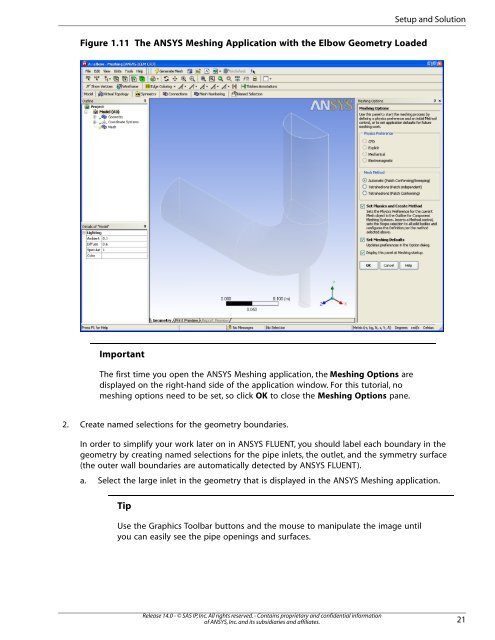
Figure 1.11 The <strong>ANSYS</strong> Meshing Application with the Elbow Geometry Loaded<br />
Important<br />
The first time you open the <strong>ANSYS</strong> Meshing application, the Meshing Options are<br />
displayed on the right-hand side of the application window. For this tutorial, no<br />
meshing options need to be set, so click OK to close the Meshing Options pane.<br />
2. Create named selections for the geometry boundaries.<br />
In order to simplify your work later on in <strong>ANSYS</strong> <strong>FLUENT</strong>, you should label each boundary in the<br />
geometry by creating named selections for the pipe inlets, the outlet, and the symmetry surface<br />
(the outer wall boundaries are automatically detected by <strong>ANSYS</strong> <strong>FLUENT</strong>).<br />
a. Select the large inlet in the geometry that is displayed in the <strong>ANSYS</strong> Meshing application.<br />
Tip<br />
Use the Graphics Toolbar buttons and the mouse to manipulate the image until<br />
you can easily see the pipe openings and surfaces.<br />
Release 14.0 - © SAS IP, Inc. All rights reserved. - Contains proprietary and confidential information<br />
of <strong>ANSYS</strong>, Inc. and its subsidiaries and affiliates.<br />
Setup and Solution<br />
21