ANSYS FLUENT Tutorial Guide
ANSYS FLUENT Tutorial Guide
ANSYS FLUENT Tutorial Guide

You also want an ePaper? Increase the reach of your titles
YUMPU automatically turns print PDFs into web optimized ePapers that Google loves.
Chapter 1: Introduction to Using <strong>ANSYS</strong> <strong>FLUENT</strong> in <strong>ANSYS</strong> Workbench: Fluid Flow and Heat Transfer in a<br />
Mixing Elbow<br />
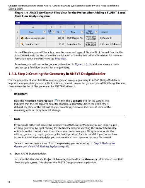
Figure 1.4 <strong>ANSYS</strong> Workbench Files View for the Project After Adding a <strong>FLUENT</strong>-Based<br />
Fluid Flow Analysis System<br />
In the Files view, you will be able to see the name and type of file, the ID of the cell that the file<br />
is associated with, the size of the file, the location of the file, and other information. For more information<br />
about the Files view, see Files View.<br />
From here, you will create the geometry described in Figure 1.1 (p. 2), and later create a mesh<br />
and set up a fluid flow analysis for the geometry.<br />
1.4.3. Step 2: Creating the Geometry in <strong>ANSYS</strong> DesignModeler<br />
For the geometry of your fluid flow analysis, you can create a geometry in <strong>ANSYS</strong> DesignModeler, or<br />
import the appropriate geometry file. In this step, you will create the geometry in <strong>ANSYS</strong> DesignModeler,<br />
then review the list of files generated by <strong>ANSYS</strong> Workbench.<br />
8<br />
Important<br />
Note the Attention Required icon ( ) within the Geometry cell for the system. This<br />
indicates that the cell requires data (for example, a geometry). Once the geometry is<br />
defined, the state of the cell will change accordingly. Likewise, the state of some of the<br />
remaining cells in the system will change.<br />
Note<br />
If you would rather not create the geometry in <strong>ANSYS</strong> DesignModeler, you can import a preexisting<br />
geometry by right-clicking the Geometry cell and selecting the Import Geometry<br />
option from the context menu. From there, you can browse your file system to locate the<br />
elbow_geometry.agdb geometry file that is provided for this tutorial. If you do not have<br />
access to <strong>ANSYS</strong> DesignModeler, you can use the elbow_geometry.stp file instead.<br />
To learn how to create a mesh from the geometry you imported, go to Step 3: Meshing the<br />
Geometry in the <strong>ANSYS</strong> Meshing Application (p. 19).<br />
1. Start <strong>ANSYS</strong> DesignModeler.<br />
In the <strong>ANSYS</strong> Workbench Project Schematic, double-click the Geometry cell in the elbow fluid<br />
flow analysis system. This displays the <strong>ANSYS</strong> DesignModeler application.<br />
Release 14.0 - © SAS IP, Inc. All rights reserved. - Contains proprietary and confidential information<br />
of <strong>ANSYS</strong>, Inc. and its subsidiaries and affiliates.