Q-TRAN - International Meshing Roundtable - Sandia National ...
Q-TRAN - International Meshing Roundtable - Sandia National ...
Q-TRAN - International Meshing Roundtable - Sandia National ...

Create successful ePaper yourself
Turn your PDF publications into a flip-book with our unique Google optimized e-Paper software.
A-PDF Split DEMO : Purchase from www.A-PDF.com to remove the watermark<br />
Q-<strong>TRAN</strong>: A New Approach to Transform<br />
Triangular Meshes into Quadrilateral Meshes<br />
Locally<br />
Mohamed S. Ebeida 1 , Kaan Karamete 2 , Eric Mestreau 2 , and Saikat Dey 2<br />
1 Org. 1414, Applied Math and Applications, <strong>Sandia</strong> <strong>National</strong> Laboratories<br />
msebeid@sandia.gov<br />
2 Code 7130, Physical Acoustics Branch, Naval Research Laboratories<br />
karamete@pa.nrl.navy.mil , eric.mestreau.ctr@nrl.navy.mil,<br />
saikat.dey@nrl.navy.mil<br />
Summary. Q-Tran is a new indirect algorithm to transform triangular tessellation<br />
of bounded three-dimensional surfaces into all-quadrilateral meshes.<br />
The proposed method is simple, fast and produces quadrilaterals with provablygood<br />
quality and hence it does not require a smoothing post-processing step.<br />
The method is capable of identifying and recovering structured regions in<br />
the input tessellation. The number of generated quadrilaterals tends to be<br />
almost the same as the number of the triangles in the input tessellation. Q-<br />
Tran preserves the vertices of the input tessellation and hence the geometry<br />
is preserved even for highly curved surfaces. Several examples of Q-Tran are<br />
presented to demonstrate the efficiency of the proposed method.<br />
Keywords: Mesh generation, all-quadrilateral, indirect methods, curved surfaces.<br />
1 Introduction<br />
Automatic mesh generation is one of the main procedures in Finite Element<br />
Analysis (FEA) as well as many other fields. Hence, a robust automatic mesh<br />
generator becomes an indispensable tool in such applications. Nowadays, the<br />
generation of triangular meshes on 3D surfaces by either the Delaunay triangulation<br />
[1, 2, 3, 4] or the advancing front technique [5, 6, 7, 8] are considered<br />
matured. However, in many applications, quadrilaterals are preferable to triangular<br />
meshes due to their superior performance for various applications<br />
such as sheet metal forming and crash simulations. A smaller set of literature<br />
exists for quadrilateral meshing. In the last decade, different approaches have<br />
been proposed in the area of unstructured all-quadrilateral mesh generation.
2 Mohamed S. Ebeida, Kaan Karamete, Eric Mestreau, and Saikat Dey<br />
Virtually, all existing quadrilateral meshing algorithms can be grouped into<br />
two main categories, namely, the direct and the indirect approaches.<br />
In the indirect methods, quadrilaterals are formed based on a triangular<br />
tessellation called a background mesh. The simplest approach under this category<br />
is to divide each triangular face into three quadrilaterals by inserting a<br />
vertex into at the center of each face as well as splitting all of its three edges.<br />
This method is fast, robust and preserves the angle bounds of the background<br />
mesh. However it triples the number of the faces of the input tessellation and<br />
introduce a large number of irregular vertices, which are usually not favored<br />
in many applications. An irregular vertex is an internal vertex with valence<br />
number other than four. An alternative method is to combine adjacent pairs<br />
of triangles to form a single quadrilateral [9, 10]. The drawback of this method<br />
that in order to generate a mesh with good quality, many triangular faces in<br />
the initial tessellation might be left in the output mesh. To minimize the number<br />
of these remaining triangles, several heuristic procedures suggested to control<br />
the order in which triangles are combined, and in some cases split during<br />
the conversion[11, 12, 13]. Velho proposed a local transformation method that<br />
utilizes clustering of triangular pairs and produce all-quadrilateral meshes[14].<br />
Owen et al. [15] developed an advancing front algorithm, Q-MORPH, based<br />
on a background mesh and the techniques used in the paving algorithm [16].<br />
Q-MORPH generates an all-quadrilateral mesh with well aligned rows of elements<br />
and a fewer number of irregular vertices. However, this method needs<br />
an initial front to start the quadrilateral conversion and the quality of the generated<br />
quadrilaterals depends heavily on that front. This might be a problem<br />
for applying Q-MORPH to closed 3D triangular tessellation that is not associated<br />
with sharp features. Miyazaki et al. proposed a method to generate a<br />
suitable initial front in these cases[17]. However, the Q-Morph transformation<br />
is still not local, since each triangular face cannot be transformed unless it becomes<br />
adjacent to the advancing front. Moreover, Q-Morph does not preserve<br />
the vertices of the input tessellation which may alter the associated geometry<br />
for a curved input surface.<br />
On the other hand, in the direct methods, quadrilaterals are directly created<br />
over the problem domain. These methods are generally classified into<br />
one of three main categories. The first depends on some form of domain decomposition<br />
[18, 19, 20]. The second is based on the advancing front method<br />
[21, 16, 22]. The third extracts a quadrilateral surface using a Cartesian grid<br />
[23] or packing of circles [24]. In general, direct methods are slower and less<br />
robust compared to indirect methods.<br />
The main objective of this study is to present a new indirect quadrilateral<br />
mesh generation scheme over 3D curved surface while preserving the vertices<br />
of the input triangular tessellation. The proposed method is partially similar<br />
to the technique proposed by Velho [14]; however, Q-Tran produces fewer<br />
quadrilaterals and fewer irregular vertices in general.
Q-<strong>TRAN</strong>: Transform Triangular Meshes into Quadrilateral Meshes 3<br />
2 Outline of the Q-Tran algorithm<br />
The Q-Tran algorithm is briefly outlined in the following steps:<br />
1. Initial edge classification: Each edge in the input triangular tessellation is<br />
classified as one of the following six types (see Figure 1)<br />
• A boundary edge, BE, is either an edge adjacent to a single triangular<br />
face or associated with a sharp feature or specified by the user.<br />
• An anisotropic diagonal edge, ADE, is a non-boundary edge adjacent<br />
to two triangular faces such that its length is greater than the length<br />
of the remaining four edges and at least one of the two triangle is<br />
anisotropic. A triangular face is considered anisotropic if its aspect<br />
ratio exceeds 3.0 otherwise it is considered to be isotropic.<br />
• An isotropic diagonal edge, IDE, is an edge that does not fall into any<br />
of the two categories mentioned above and adjacent to two isotropic<br />
triangular faces such that its length is greater than the length of the<br />
remaining four edges and none of these edges is a boundary edge.<br />
• A corner edge, CE, is an edge that does not fall into any of the three<br />
categories mentioned above and adjacent to two isotropic triangular<br />
faces with at least one of these two has two boundary edges.<br />
• A regular edge, RE, is any other edge that does not fall into any of the<br />
four categories mentioned above.<br />
• A special regular edge, SRE, is a regular edge with two adjacent triangles<br />
that has two aligned boundary edges.<br />
2. Reclassification of regular and corner edges:<br />
• A regular edge that shares a vertex with an anisotropic diagonal edge<br />
is reclassified as a boundary edge.<br />
• A special regular edge is reclassified as a boundary edge.<br />
• A corner edge is reclassified into an anisotropic diagonal edge if its two<br />
adjacent faces has four boundary edges.<br />
• A corner or a regular edge is reclassified into a boundary edge if it<br />
would result in violating the angle bounds of the input tessellation<br />
during the conversion process.<br />
3. Check for optimal solution: If the number of diagonal edges is half the<br />
number of the faces in the input tessellation, an optimal solution exists.<br />
Retrieve it by merging the two adjacent triangles to each diagonal edge<br />
into a single quad and exit, otherwise proceed to the next step.<br />
4. Creation of new vertices:<br />
• Create a vertex, edge vertex, at the center of non-regular edge.<br />
• Create a vertex, regular face vertex, at the center of each triangular<br />
face with three regular edges or with two boundary edges.<br />
• Create a vertex, boundary face vertex, at the center of each triangular<br />
face with three boundary edges.<br />
5. Quadrilateral formation:<br />
• For each boundary face vertex, generate three quadrilaterals by splitting<br />
the associated boundary face into three quadrilaterals.
4 Mohamed S. Ebeida, Kaan Karamete, Eric Mestreau, and Saikat Dey<br />
• For each anisotropic diagonal edge, transform the adjacent two triangles<br />
into four quadrilaterals.<br />
• For each regular edge, generate a quadrilateral using the two vertices<br />
of that edge and the two created vertices in the adjacent faces.<br />
• For each corner edge generate the quadrilaterals as shown in Figure<br />
3(b).<br />
6. Topology clean-up:<br />
• Minimize the number of irregular vertices using face collapse of the<br />
quadrilaterals with two opposite tri-valence vertices that are created<br />
during the Q-Tran algorithm. Do not execute this step if the quality<br />
will deteriorate due this heuristic operation. This operation is illustrated<br />
in Figure 2.<br />
(a) ADE (b) ADE (c) IDE<br />
(d) CE<br />
(e) SRE<br />
Fig. 1. Classification of the edges of the input tessellation.<br />
3 Quality of the generated mesh<br />
In this section, we study the quality of the quadrilaterals generated during<br />
the Q-Tran algorithm in terms of preserving the angle bounds of the input<br />
tessellation. As mentioned in the previous section, there are six cases associated<br />
with the generation of the quadrilaterals within Q-Tran. The first three<br />
types, Group A, are illustrated in Figure 3(a). In these cases, the angle bounds<br />
of the input tessellation are preserved automatically. The proof is trivial and<br />
follows the simple fact:<br />
min(x, y) ≤ x + y ≤ max(x, y) (1)<br />
2<br />
where x and y in Equation 1 represents two adjacent angles in the triangular<br />
tessellation while x+y<br />
2<br />
represents the corresponding angle in the quadrilateral<br />
tessellation.
Q-<strong>TRAN</strong>: Transform Triangular Meshes into Quadrilateral Meshes 5<br />
(a) Input<br />
(b) Output<br />
Fig. 2. Topology clean-up using face collapse to reduce the number of irregular<br />
vertices. A quadrilateral face is collapsed converting two irregular vertices into a<br />
regular one. The triangular tessellation is shown using dotted lines in both figures.<br />
For the second group, the quality of the input tessellation is preserved<br />
by construction, where an edge from Group B would be reclassified into an<br />
edge from Group A if it causes a violation to the angle bounds of the input<br />
tessellation. However, we note that throughout the test problems that we have<br />
used in this paper we have never encountered this case. Further investigations<br />
are required to prove that this case can ever exists.<br />
4 Analysis of Q-Tran performance<br />
In order to test the performance of Q-Tran, we generated a sequence of triangular<br />
tessellations covering a planar hexagon. A triangular tessellation,<br />
M i , i = 2, 3, ..., 7, is obtained by isotropic refinement of the previous tessellation,<br />
M i−1 , where each triangular face is split into four triangular faces.<br />
Q-Tran is then utilized to convert each tessellation in this sequence into an<br />
all-quadrilateral mesh. Note that all the internal edges in any tessellation here<br />
are regular edges, which means that random Topology clean-up will be applied<br />
everywhere in the mesh at the end of the algorithm. This should represent<br />
a worst case scenario for Q-Tran with regard to the time of execution, given<br />
that the algorithm should have the same performance for planar and curved<br />
surfaces. The results of this test are summarized in Table 1. As we notice from<br />
these results, random clean-up operations might increase the relative number<br />
of the generated quadrilaterals in some cases to be as much as twice the number<br />
of the faces in the input tessellation. All of the tests performed in this<br />
section were performed using a 32-bit operating system and 2.0 GHz (T7250)<br />
processor with 2.0 GB of memory. Q-Tran was implemented in a generic function<br />
so the performance might vary based on the utilized datastructure.
6 Mohamed S. Ebeida, Kaan Karamete, Eric Mestreau, and Saikat Dey<br />
(a) Group A<br />
(b) Group B<br />
Fig. 3. Quadrilateral formation in Q-Tran. The quality of the quadrilaterals generated<br />
in Group A is guaranteed automatically while the quality of the quadrilaterals<br />
generated in Group B is guaranteed by construction.<br />
Table 1. Performance of Q-Tran for the hexagon problem.<br />
Model Name Num T Num Q Num Q/Num T Time (seconds) Rate (Num T /min.)<br />
Hexagon-3 96 158 1.65 0.451 12,700<br />
Hexagon-4 384 668 1.74 0.486 47,407<br />
Hexagon-5 1,536 2,920 1.90 0.557 165,457<br />
Hexagon-6 6,144 11,856 1.93 1.359 271,258<br />
Hexagon-7 24,576 47,458 1.93 4.206 350,584<br />
Hexagon-8 98,304 104,976 1.07 13.219 446,194<br />
Hexagon-9 393,219 405,914 1.03 54.880 429,904<br />
The performance of Q-Tran is mainly affected by the relative number<br />
different edges categories in the input tessellation. For example, if all the edges<br />
are classified as boundary edges, then the number of the faces of the input<br />
tessellation will be quadrupled. On the contrary, if the number of diagonal<br />
edges in the mesh is half the number of the faces of the input tessellation,<br />
then the latter will be reduced by half in the output mesh. For most cases,<br />
where the relative ratio of internal to boundary edges is relatively large, Q-
Q-<strong>TRAN</strong>: Transform Triangular Meshes into Quadrilateral Meshes 7<br />
(a) (b) (c) (d)<br />
(e) (f) (g) (h)<br />
Fig. 4. The first four meshes in a sequence utilized to test the performance of Q-<br />
Tran. The upper figures show the triangular tessellation of a Hexagon while the<br />
lower figures show the corresponding quadrilateral meshes.<br />
Tran tends to almost preserve the number of the faces in the input tessellation.<br />
With regard to the required computational time, Q-Tran tends to be much<br />
faster as the number of diagonal edges relatively increase, since fewer clean-up<br />
operations would be required. As shown in the next section we have applied<br />
Q-Tran to a wide range of different types meshes. Some of these meshes have<br />
some structured patches with anisotropic faces, others are decomposed of<br />
highly curved surfaces with no boundary edges at all, ... etc. The performance<br />
of Q-Tran for these meshes is summarized in Table 2.<br />
Table 2. Performance of Q-Tran for various problems.<br />
Model Name Num T Num Q Num Q/Num T Time (seconds) Rate (Num T /min.)<br />
hook 1,014 1,212 1.20 3.350 18,161<br />
ref-plane 3,406 3,776 1.11 0.933 219,035<br />
siklone-1 29,428 31,749 1.08 6.809 259,315<br />
siklone-2 117,716 123,892 1.05 18.855 374,593<br />
siklone-3 470,864 487,156 1.03 70.674 399,748<br />
topology-1 35,000 41,993 1.20 7.244 289,895<br />
topology-2 140,0000 171,785 1.23 23.989 350,160<br />
vase-1 19,460 27,508 1.41 6.28 185,923<br />
vase-2 77,844 107,546 1.38 14.346 325,570<br />
vase-3 311,360 419,060 1.35 53.685 347,985<br />
tori-1 12,000 12,129 1.01 2.769 260,021<br />
tori-2 48,000 49,788 1.04 7.412 388,559<br />
tori-3 192,016 197,252 1.03 28.422 405,353
8 Mohamed S. Ebeida, Kaan Karamete, Eric Mestreau, and Saikat Dey<br />
To have an overall average estimation of the Q-Tran performance, the results<br />
of all the test performed in this section are illustrated in Figure 5. These<br />
results shows that the number of the quadrilaterals in most cases tends to be<br />
almost the same as the number of the triangles in the input. This may increase<br />
in the worst cases to be as much as twice that number. On average, Q-Tran<br />
seems to convert a triangular tessellation into an all-quadrilaterals meshes at<br />
an average rate of 375,000 triangles per minute using a 2.0 GHz processor.<br />
Again, this is considered a rough estimation since we utilized a generic implementation<br />
These results might be further improved if a datastructure-specific<br />
implementation is to be utilized because Q-Tran depends to a large extent on<br />
the speed of adjacency queries.<br />
(a) Input<br />
(b) Output<br />
Fig. 5. Q-Tran performance. The relation between the number of the faces in the<br />
input and the output meshes is illustrated in the right figure while the execution<br />
time for the various test problems is illustrated in the left figure. The inclined line<br />
in each of the two figures is used as a reference.<br />
5 Example Problems<br />
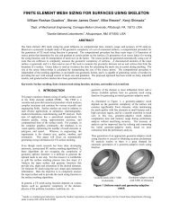
Six examples, shown in Figures 6-11, demonstrates various features of the<br />
Q-Tran algorithm. The first example shown in Figure 6 demonstrates the capability<br />
of Q-Tran to handle highly curved surfaces with no boundary edges.<br />
This example illustrates the ability of Q-Tran to detect and preserve structured<br />
regions in the input tessellation. Figure 7, on the other hand, shows the<br />
quality of the quadrilaterals generated for a Cad model with non-manifold<br />
boundary edges. This example includes almost all the types of edge classifications<br />
within Q-Tran.<br />
The ability to handle a triangular mesh with some anisotropic faces is illustrated<br />
in Figures 8. As this figure show, the final quadrilateral mesh preserves<br />
the directionality of the stretched faces.
Q-<strong>TRAN</strong>: Transform Triangular Meshes into Quadrilateral Meshes 9<br />
Figures 9 and 10 show that the vertices distribution in the final quadrilateral<br />
mesh is almost the same as in the input tessellation. This is demonstrated<br />
using a highly curved surface as well as a simple planar surface with variable<br />
density distribution.<br />
The final example, in Figure 11, demonstrates that efficiency of recovering<br />
the structured regions from the input tessellation. As illustrated in that figure<br />
Q-Tran was capable of recovering all of the structured regions in this example<br />
leaving behind a very small number of irregular vertices.<br />
6 Conclusion<br />
The Q-Tran algorithm is an indirect quadrilateral meshing algorithm that<br />
utilizes edge classification to transform triangles into quadrilaterals locally. It<br />
generates an all-quadrilateral mesh with provably-good quality. The resulting<br />
quadrilaterals, in general, follow the boundaries of the domain. The Q-Tran<br />
algorithm is capable of detecting and recovering the structured regions in the<br />
input tessellation. It can handle isotropic and anisotropic cases with almost<br />
the same efficiency. Compared to the Q-Morph algorithm, Q-Tran can be implemented<br />
in parallel, preserves the vertices of the input tessellation and does<br />
not require an initial front. Moreover, the quality of the generated quadrilaterals<br />
is guaranteed, hence, no smoothing is required as a post processing<br />
step. Improvements include minimizing of the irregular vertices as well as<br />
controlling the directionality in the isotropic structured regions.<br />
Acknowledgments<br />
This research was performed under contract to US Naval Research Laboratory<br />
as part of the Computational Research and Engineering Acquisition Tools and<br />
Environments (CREATE) program of the DoD High Performance Computer<br />
Modernization Program. We would like to thank Dave Morris, and Frank Su<br />
for the “Topology” and the “Vase” models. These models are courtesy of 3dvia<br />
(http://www.3dvia.com). We would also like to thank Herbert Edelsbrunner,<br />
(http://www.cs.duke.edu/ ∼ edels/Tubes/), for the “Tori” model.
10 Mohamed S. Ebeida, Kaan Karamete, Eric Mestreau, and Saikat Dey<br />
(a) Input: 35,000 triangles<br />
(b) Output: 41,993 quadrilaterals<br />
Fig. 6. Topology Model (execution time = 7.244 seconds)<br />
(a) Input: 1,014 triangles<br />
(b) Output: 1,212 quadrilaterals<br />
Fig. 7. Hook Model (execution time = 3.35 seconds)<br />
(a) Input: 19,460 triangles<br />
(b) Output: 27,508 quadrilaterals<br />
Fig. 8. Vase Model (execution time = 6.28 seconds)
Q-<strong>TRAN</strong>: Transform Triangular Meshes into Quadrilateral Meshes 11<br />
(a) Input: 29,428 triangles<br />
(b) Output: 31,749 quadrilaterals<br />
Fig. 9. Siklone Model (execution time = 6.809 seconds)<br />
(a) Input: 3,406 triangles<br />
(b) Output: 3,770 quadrilaterals<br />
Fig. 10. Refined-Plane Model (execution time = 0.933 seconds)<br />
(a) Input: 12,000 triangles<br />
(b) Output: 12,129 quadrilaterals<br />
Fig. 11. Tori Model (execution time = 2.769 seconds)
12 Mohamed S. Ebeida, Kaan Karamete, Eric Mestreau, and Saikat Dey<br />
References<br />
1. L. P. Chew. Constrained Delaunay triangulations. Algorithmica, 4:97–108, 1989.<br />
2. T. K. Dey, C. L. Bajaj, and K. Sugihara. On good triangulations in three<br />
dimensions. Int. J. Comput. Geom. & App., 2:75–95, 1992.<br />
3. G. L. Miller, D. Talmor, S.-H. Teng, and N. Walkington. A Delaunay based<br />
numerical method for three dimensions: generation, formulation, and partition.<br />
In 27th Annual ACM Symposium on the Theory of Computing, pages 683–692,<br />
1995.<br />
4. D. Cohen-Steiner, E. Colin, and M. Yvinec. Conforming Delaunay triangulations<br />
in 3D. In 18th Annual Symposium on Computational Geometry, pages 199–208,<br />
2002.<br />
5. P. L. George and E. Seveno. The advancing front mesh generation method<br />
revisited. Int. J. Numer. Meth. Engng., 37:3605–3619, 1994.<br />
6. D. J. Mavriplis. An advancing front Delaunay triangulation algorithm designed<br />
for robustness. J. of Comput. Phys., 117:90–101, 1995.<br />
7. R. Lohner. Extensions and improvements of the advancing front grid generation<br />
technique. Commun. Numer. Meth. Engng., 12:683–702, 1996.<br />
8. T. S. Lau and S. H. Lo. Finite element mesh generation over analytical surfaces.<br />
Comput. Struct., 59:301–309, 1996.<br />
9. E. A. Heighwayl. A mesh generator for automatically subdividing irregular<br />
polygons into quadrilaterals. IEEE Transactions on Magnetics, Mag-19:2535–<br />
2538, 1983.<br />
10. T. Itoh, K. Inoue, A. Yamada, K. Shimada, and T. Furuhata. Automated<br />
conversion of 2D triangular Mesh into quadrilateral mesh with directionality<br />
control. In 7th <strong>International</strong> <strong>Meshing</strong> <strong>Roundtable</strong>, pages 77–86, 1998.<br />
11. S. H. Lo. Generating quadrilateral elements on plane and over curved surfaces.<br />
Comput. Struct., 31:421–426, 1989.<br />
12. B. P. Johnston, J. M. Sullivan Jr., and A. Kwasnik. Automatic conversion of<br />
triangular finite element meshes to quadrilateral elements. Int. J. Numer. Meth.<br />
Engng., 31:67–84, 1991.<br />
13. C. K.Lee and S. H. Lo. A new scheme for the generation of a graded quadrilateral<br />
mesh. Comput. Struct., 52:847–857, 1994.<br />
14. L. Velho. Quadrilateral meshing using 4-8 clustering. In CILANCE00, pages<br />
61–64, 2000.<br />
15. S. J. Owen, M. L. Staten, S. A. Canann, and S. Saigal. Q-Morph: An indirect<br />
approach to advancing front quad meshing. Int. J. Numer. Meth. Engng.,<br />
44:1317 – 1340, 1999.<br />
16. T. D. Blacker and M. B. Stephenson. Paving: A new approach to automated<br />
quadrilateral mesh generation. Int. J. Numer. Meth. Engng., 32:811–847, 1991.<br />
17. R. Miyazaki and K. Harada. Transformation of a closed 3D triangular mesh<br />
to a quadrilateral mesh based on feature edges. Int. J. Comput. Sci. Network<br />
Security., 9:30–36, 2009.<br />
18. P. L. Baehmann, S. L. Wittchen, M. S. Shephard, K. R. Grice, and M. A. Yerry.<br />
Robust geometrically based, automatic two-dimensional mesh generation. Int.<br />
J. Numer. Meth. Engng., 24:1043–1078, 1987.<br />
19. T. K. H. Tam and C. G. Armstrong. 2D finite element mesh generation by<br />
medial axis subdivision. Adv. Engng. Software, 13:313–324, 1991.<br />
20. B. Joe. Quadrilateral mesh generation in polygonal regions. Comput. Aid. Des.,<br />
27(3):209–222, 1991.
Q-<strong>TRAN</strong>: Transform Triangular Meshes into Quadrilateral Meshes 13<br />
21. J. Z. Zhu, O. C. Zienkiewicz, E. Hinton, and J. Wu. A new approach to the<br />
development of automatic quadrilateral mesh generation . Int. J. Numer. Meth.<br />
Engng., 32:849–866, 1991.<br />
22. D. R. White and P. Kinney. Redesign of the paving algorithm: Robustness enhancements<br />
through element by element meshing. In 6th <strong>International</strong> <strong>Meshing</strong><br />
<strong>Roundtable</strong>, pages 323–335, 1997.<br />
23. Y. Zhang and C. Bajaj. Adaptive and quality quadrilateral/hexahedral meshing<br />
from volumetric Data. Comput. Meth. in Appl. Mech. Engng., 195:942–960,<br />
2006.<br />
24. M. Bern and D. Eppstein. Quadrilateral meshing by circle packing. Int. J.<br />
Comp. Geom. & Appl., 10(4):347–360, 2000.