Manual Drawing Structural Steelwork - Industrial Centre
Manual Drawing Structural Steelwork - Industrial Centre
Manual Drawing Structural Steelwork - Industrial Centre

Create successful ePaper yourself
Turn your PDF publications into a flip-book with our unique Google optimized e-Paper software.
<strong>Manual</strong> <strong>Drawing</strong><br />
<strong>Structural</strong> <strong>Steelwork</strong><br />
<strong>Industrial</strong> <strong>Centre</strong><br />
The Hong Kong Polytechnic University
Definition<br />
• The structural steel is steel structure made<br />
up of the following load-bearing steel<br />
elements connected by bolts or welding :<br />
- beams<br />
- girders<br />
- trusses<br />
- stanchions<br />
- bracing
<strong>Structural</strong> Steel work<br />
(BS 449, BS 5950)<br />
• Grade 43<br />
• Grade 50<br />
• Grade 55
<strong>Structural</strong> Design<br />
• Safety<br />
• Serviceability
Steel Cross-Section<br />
• I - Universal Beam/Column<br />
• U - Channel<br />
• L - Angle<br />
• T - Tee<br />
• - Hollow Sections<br />
• Girder
Beams<br />
• Beams are structural elements carrying<br />
loads from slabs.<br />
• The loads are resisted by bending and shear<br />
in the beams<br />
• There are 3 types of beams:<br />
– Simply support beams<br />
– Continuous beams<br />
– Cantilevered beams
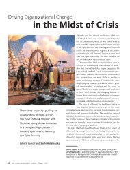
Columns/Stanchions<br />
• Stanchions are vertical<br />
members supporting<br />
floors and beams in<br />
building
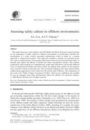
Connections<br />
• Connections join individual<br />
elements together to form the<br />
structural frame, for example,<br />
floor beams to stanchions in a<br />
building
Types of Connections<br />
• Bolts<br />
• Welding
Bolt Connections<br />
• Black bolts<br />
• High-strength friction-<br />
grip bolts
Basic components (3)<br />
• The nominal form of the steel components<br />
(members) and bolts are standardized in series<br />
and specified by the relevant Standards, such<br />
as BS4190, BS3692, BS4395 and BS5135.
Common form of <strong>Steelwork</strong>s<br />
<strong>Steelwork</strong>s can appear in the following form :<br />
• To carry loads over a span :<br />
• Universal beam<br />
• Castellated beam<br />
• Plate girder<br />
• Truss<br />
• Lattice<br />
• Vierendeel girder<br />
• Portal frame<br />
• Space frame<br />
• To carry vertical loads<br />
• Universal column<br />
• Laced stanchion<br />
• Battened stanchion
Use together with concrete<br />
• <strong>Steelwork</strong>s are in some situations used<br />
with concrete for :<br />
• composite beam (concrete to be the<br />
compression member at top)<br />
• foundations<br />
• Protection to steel
<strong>Drawing</strong>s contents<br />
The drawings should show the steelworks for<br />
different levels of details :<br />
(a) layout of the whole structures for which the steel<br />
works are to form – by plans and elevations<br />
(b) Layout of the steelworks (e.g. a truss) – by plans<br />
and elevations<br />
(c) Details of connections of the steelworks– by plans,<br />
elevations and sections, even isometric views.
<strong>Drawing</strong> for <strong>Steelwork</strong>s layout<br />
The following information are relevant :<br />
• The general dimensions of the steelworks<br />
• The nominal size of the members<br />
(e.g. 305x102x25kg/m UB)<br />
• The centre lines (or line of centroid) ) of members<br />
forming the framework.<br />
• The arrangements of connection (referred to<br />
enlarged details where necessary)
<strong>Drawing</strong>s for connection details<br />
The following information are relevant :<br />
(a) for bolting<br />
(b) for welding<br />
• The number and<br />
diameter of bolts<br />
• Provision of washers<br />
• Diameter of bolt holes<br />
• Position/spacing of bolt<br />
holes<br />
• Edge distance to hole<br />
• form of weld (e.g. fillet,<br />
butt.)<br />
• size of weld (leg length)<br />
• weld length<br />
• spacing of intermittent<br />
welds<br />
• symbols as recommended<br />
by BS 499.
Glossary<br />
The following terms may be used in drawing to<br />
describe steelworks :<br />
• Flange<br />
• Web<br />
• Web stiffener<br />
• Cleat<br />
• Bracket<br />
• End plate to tube<br />
• Base<br />
(to stanchion)<br />
• Gusset<br />
• Splice<br />
• Tie (of a truss)<br />
• Top chord<br />
(of a truss)<br />
• Bottom chord<br />
(of a truss)<br />
• Strut (of a truss)<br />
• Countersunk bolt<br />
• Shank/thread of<br />
bolt<br />
• Backing<br />
(to contain weld)
Specifications given in the drawings<br />
The drawing notes may specify the following :<br />
• Grade of the steel members.(e.g. Grade 43C)<br />
• Grade of the bolts (e.g. Black bolts, stainless steel bolts.)<br />
• Method to form holes and to cut member<br />
• Method of welding<br />
• Tolerance of fabrication<br />
• Treatment to steel surface (hot-dip galvanized, painting, etc.)
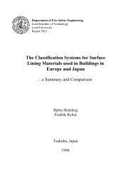
Typical Connection of Joint
Black Bolts Connections<br />
4 No. 20 mm dia.<br />
black bolts<br />
Stanchion<br />
“A”<br />
Beam<br />
B3<br />
Elevation
6 mm fillet weld<br />
171<br />
Beam<br />
B3<br />
352<br />
200<br />
Stanchion<br />
“A”<br />
Elevation