GEA Flex-Geko Comfort-Edition - GEA Happel Belgium
GEA Flex-Geko Comfort-Edition - GEA Happel Belgium
GEA Flex-Geko Comfort-Edition - GEA Happel Belgium

You also want an ePaper? Increase the reach of your titles
YUMPU automatically turns print PDFs into web optimized ePapers that Google loves.
<strong>Flex</strong>ible solution for any requirement<br />
<strong>GEA</strong> <strong>Flex</strong>-<strong>Geko</strong><br />
<strong>Comfort</strong>-<strong>Edition</strong><br />
Fan Coil Units | Data & Facts<br />
Now available with<br />
highly efficient EC motors!<br />
geprüfte RLT-Hygiene<br />
VDI 6022 (D)<br />
Hygiene - Siegel<br />
geprüft<br />
SWKI VA<br />
104-01 (CH)<br />
durc h<br />
ILH<br />
BERLIN<br />
<strong>GEA</strong> Heat Exchangers / HVAC Systems
Table of Contents<br />
<strong>GEA</strong> <strong>Flex</strong>-<strong>Geko</strong> <strong>Comfort</strong> <strong>Edition</strong><br />
Copyright note<br />
Disclosing, copying, distributing or taking any action in reliance on the contents of this document is strictly<br />
prohibited without express prior consent. Violations entail liability for any damages or other liability arising.<br />
All rights in relation to patents, utility patents or design patents are reserved.<br />
Unit Sizes ....................................................................................................................................... 3<br />
Fan Coil Unit Components ........................................................................................................... 4<br />
Unit Selection ................................................................................................................................ 5<br />
Unit Description ............................................................................................................................ 6<br />
EC Technology: Keyword Energy Efficiency ............................................................................. 8<br />
Recirculating Unit Cooling and Heating 4-Pipe Chilled and Warm Water ............................. 12<br />
Recirculating Unit Cooling and Heating 2-Pipe Chilled Water and Electric Heating ............ 16<br />
Recirculating Unit Cooling and Heating Direct Evaporator and 2-Pipe Warm Water ........... 20<br />
Recirculating Unit Cooling or Heating 2-Pipe Chilled or Warm Water.................................... 24<br />
Recirculating Unit Cooling or Heating 2-Pipe Chilled or Warm Water<br />
with Auxiliary Electrical Heating ................................................................................................ 28<br />
Recirculating Unit Heating 2-Pipe Warm Water ........................................................................ 32<br />
Recirculating Unit Heating Full Electric Heating ..................................................................... 36<br />
Recirculating Unit Cooling 2-Pipe Chilled Water ..................................................................... 40<br />
Recirculating Unit Cooling Direct Evaporator .......................................................................... 44<br />
Mixing Unit Cooling and Heating 4-Pipe Chilled and Warm Water ......................................... 48<br />
Mixing Unit Cooling and Heating Direct Evaporator and 2-Pipe Warm Water ....................... 52<br />
Mixing Unit Cooling or Heating 2-Pipe Chilled or Warm Water .............................................. 56<br />
Mixing Unit Heating 2-Pipe Warm Water .................................................................................. 60<br />
Mixing Unit Heating Full Electric Heating.................................................................................. 64<br />
Pressure Drop in Heat Exchanger ............................................................................................. 68<br />
Example to Determine Capacity ................................................................................................ 69<br />
Acoustics ..................................................................................................................................... 70<br />
Sound Pressure Level, Sound Power Level ............................................................................. 72<br />
NR and NC Limiting Curves ....................................................................................................... 73<br />
Definition of Air Flow / Installation Examples .......................................................................... 74<br />
Dimensions of Basic Units without Casing .............................................................................. 75<br />
Dimensions and Medium Connections ..................................................................................... 76<br />
Dimensions of Unit Casings ...................................................................................................... 77<br />
Dimensions of Accessories – <strong>GEA</strong> Drive .................................................................................. 79<br />
Dimensions of Accessories – Air-Side Accessories................................................................ 80<br />
Control Behaviour of Valves ...................................................................................................... 84<br />
Overview of Valves ..................................................................................................................... 85<br />
Selection Table ............................................................................................................................... 85<br />
Valves (loose) with Modulating Actuator (230 V~ and 24 V~)/3-Point Operation ........................... 86<br />
Valves with Modulating Actuator (230 V~) a. 2 Volt Free Auxiliary Switches/3-Point Operation .... 87<br />
Valves with Thermoelectrical Actuators (230 V~ and 24 V~)/2-Point Operation............................. 88<br />
Valves with Continuous Actuators (24 V~, 0 ... 10 V) ..................................................................... 89<br />
Thermostatical Expansion Valve..................................................................................................... 90<br />
Shut Off Valves ............................................................................................................................... 91<br />
Ball Cocks....................................................................................................................................... 92<br />
Controls using Thermostat/Miniature Switches/Controls by Others ..................................... 93<br />
Operation of thermostat and miniature switches .................................................................... 94<br />
<strong>GEA</strong> MATRIX Controls ............................................................................................................... 95<br />
System Description......................................................................................................................... 96<br />
Features.......................................................................................................................................... 97<br />
Installation of Control Panel............................................................................................................ 98<br />
Sensor/Accessories ........................................................................................................................ 99<br />
Global Modules............................................................................................................................. 100<br />
MATRIX.Clock Timer .................................................................................................................... 101<br />
MATRIX.PC Service Software ......................................................................................................101<br />
Control Panel for All Groups ......................................................................................................... 102<br />
Unit Type Code ......................................................................................................................... 103<br />
2 PR-2011-0114-GB • Subject to modifications • Status 10/2011
<strong>GEA</strong> <strong>Flex</strong>-<strong>Geko</strong> <strong>Comfort</strong> <strong>Edition</strong><br />
Unit Sizes<br />
For Wall and Ceiling Installation<br />
Model size<br />
Width<br />
[mm]<br />
Air flow rate<br />
[m 3 /h]<br />
Sound pressure<br />
level 1)<br />
[dB(A)]<br />
Capacity 2) [kW]<br />
•<br />
Heat capacity Q H<br />
•<br />
Cool capacity Q K<br />
1<br />
840 145-530
Fan Coil Unit Components<br />
For Wall and Ceiling Installation<br />
<strong>GEA</strong> <strong>Flex</strong>-<strong>Geko</strong> <strong>Comfort</strong> <strong>Edition</strong><br />
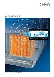
Fig. 1:<br />
Unit components (depending on unit model)<br />
1: Holding plate<br />
2: Heat exchanger<br />
3: Control panel<br />
4: Metal sheet electric control box<br />
5: Basic casing (rear wall with lateral sheet steel panels)<br />
6: Cover sheet at discharge on front side<br />
7: Bottom panel at intake on front side<br />
8: Filter element<br />
9: Main drain pan<br />
10: Fan with casing<br />
11: Suction side front panel at bottom/rear intake<br />
12: Pressure side front panel with frontal discharge<br />
13: Pressure side front panel with top/frontal discharge<br />
14: Mixing air box with actuator<br />
15: Unit foot on left side for recirculating air unit<br />
16: Unit foot on right side for recirculating air unit<br />
17: Lateral ceiling drain pan<br />
18: Lateral wall drain pan<br />
19: Unit casing<br />
20: Unit foot cover, left side<br />
21: Unit foot cover, right side<br />
22: Intake grille<br />
23: Front casing for front side discharge<br />
24: Front casing for front side intake<br />
25: Front casing for front side intake and discharge<br />
<strong>GEA</strong> is a participant in the EUROVENT certification programme.<br />
The certified products are listed in the corresponding EUROVENT lists.<br />
<strong>GEA</strong> <strong>Flex</strong>-<strong>Geko</strong> recirculating air units are certified in accordance with the hygienic requirements<br />
and regulations stipulated by VDI 6022, Sheet 1 (04/06) and SWKI VA 104-01 (04/06).<br />
4 PR-2011-0114-GB • Subject to modifications • Status 10/2011
25<br />
20<br />
15<br />
10<br />
9,0<br />
8,0<br />
7,0<br />
6,0<br />
5,0<br />
4,5<br />
4,0<br />
3,5<br />
3,0<br />
2,5<br />
2,0<br />
1,5<br />
1,0<br />
0,9<br />
0,8<br />
0,7<br />
0,6<br />
0,5<br />
50<br />
4 Rohrreihen Kühlen, 2-Leiter-System<br />
60<br />
70<br />
80<br />
90<br />
1 0<br />
150<br />
2 0<br />
30<br />
Druckverluste im Wärmetauscher<br />
250<br />
3 0<br />
350<br />
4 0<br />
450<br />
1<br />
2<br />
5 0<br />
6 7 0<br />
8 0<br />
9 Wasservolumenstrom V W [l/h]<br />
6 5 4 7<br />
Abb. 25.3<br />
<strong>GEA</strong> Top-<strong>Geko</strong> • ˜nderungen vorbehalten • Stand 08/00 (D) 25<br />
1 0<br />
3<br />
1500<br />
2 0<br />
<strong>GEA</strong> <strong>Flex</strong>-<strong>Geko</strong> <strong>Comfort</strong> <strong>Edition</strong><br />
Unit Selection<br />
Unit Description 4<br />
4-pipe chilled and warm water<br />
(4-pipe chilled and warm water with auxiliary electric heating)* 12<br />
Recirculating<br />
air<br />
Cooling<br />
and<br />
heating<br />
Cooling<br />
or<br />
heating<br />
2-pipe chilled water and electric heating 16<br />
DX evaporator and 2-pipe warm water 20<br />
2-pipe chilled or warm water 24<br />
2-pipe chilled or warm water with auxiliary electric heating 28<br />
Heating<br />
2-pipe warm water<br />
(2-pipe warm water with auxiliary electric heating)* 32<br />
Full electric heating 36<br />
Cooling<br />
2-pipe chilled water 40<br />
Direct evaporator 44<br />
Mixed air<br />
Cooling<br />
and<br />
heating<br />
Cooling<br />
or<br />
heating<br />
Heating<br />
4-chilled and warm water<br />
(2-pipe chilled water and electric heating)* 48<br />
DX evaporator and 2-pipe warm water 52<br />
2-pipe chilled or warm water<br />
(2-pipe chiiled or warm water with auxiliary electric heating)* 56<br />
2-pipe warm water<br />
(2-pipe warm water with auxiliary electric heating)* 60<br />
Full electric heating 64<br />
Cooling<br />
(2-pipe chilled water)* —<br />
(DX evaporator)* —<br />
*On request <strong>GEA</strong> will provide you data on the units indicated in brackets.<br />
DruckverlustDp [kPa]<br />
Technical data, dimensions and<br />
specification of accessories 68<br />
Valves 84<br />
<strong>GEA</strong> MATRIX control system/thermostat switches 93<br />
+<br />
PR-2011-0114-GB • Subject to modifications • Status 10/2011 5
Unit Description<br />
<strong>GEA</strong> <strong>Flex</strong>-<strong>Geko</strong> <strong>Comfort</strong> <strong>Edition</strong><br />
Ceiling unit Wall unit with mixing air box Recirculating/mixed units<br />
Heating/cooling/filtering/<br />
ventilating with 2/4-pipe<br />
system. Wall or ceiling<br />
installation (electrical and<br />
valve equipment depends on<br />
functions and requirements),<br />
basic unit made of sendzimir-galvanized<br />
metal sheet<br />
with sound and heat insulation<br />
made of polyehtylene.<br />
Fig. 2 Fig. 3<br />
<strong>Comfort</strong> casing for ceiling unit, adjustable<br />
air discharge grille, air intake bottom/rear<br />
Fig. 4 Fig. 5<br />
<strong>Comfort</strong> unit casing wall, adjustable air<br />
discharge grille (with air intake grille)<br />
<strong>Comfort</strong> unit casing<br />
made of painted metal sheet,<br />
colour white (similar to<br />
RAL 9002); plastic lateral<br />
parts and service panels,<br />
colour white (similar RAL<br />
9002) and grey (RAL 7035);<br />
adjustable plastic air<br />
discharge grille, in grey (RAL<br />
7035), or rigid version<br />
made of aluminium, naturally<br />
anodized.<br />
Thermoelectric valves Modulating valves Valves<br />
2 and 3-way valves<br />
with actuators for<br />
2-point, 230/24 V~ 50/60 Hz<br />
3-point, 230/24 V~ 50/60 Hz<br />
continuous 24 V~,<br />
control signal 0-10 V<br />
factory mounted and wired<br />
Fig. 6 Fig. 7<br />
<strong>GEA</strong> Drive<br />
Fig. 8<br />
<strong>GEA</strong> Drive<br />
Motorised and regulated discharge<br />
profile for optimisation<br />
of flow pattern and air<br />
throw in cooling mode,<br />
mounted by the factory (in<br />
combination with <strong>GEA</strong> unit<br />
casing and <strong>GEA</strong> MATRIX<br />
4000). For more features see<br />
page 79.<br />
Speed and thermostat switches MATRIX control system Control / steering systems<br />
depends on:<br />
unit configuration,<br />
fitted valves,<br />
internal/external<br />
electronic components<br />
Fig. 9 Fig. 10<br />
6 PR-2011-0114-GB • Subject to modifications • Status 10/2011
<strong>GEA</strong> <strong>Flex</strong>-<strong>Geko</strong> <strong>Comfort</strong> <strong>Edition</strong><br />
Unit Description<br />
Heat exchanger<br />
for warm / chilled water<br />
Fig. 11 Fig. 12<br />
Electric heater<br />
230 V ~/N/PE 50 Hz/3 x 400 V~ 50/60 Hz<br />
Fig. 13 Fig. 14<br />
Lateral wall /ceiling<br />
drain pan<br />
Fig. 15 Fig. 16<br />
Heat exchanger<br />
for refrigerant<br />
Centrifugal fan<br />
230 V~ 50/60 Hz<br />
Lateral wall drain pan<br />
with humidity sensor for condensate pump<br />
230 V ~ 50 Hz<br />
Heat exchanger<br />
Copper pipes with attached<br />
aluminium fins, max.<br />
operating pressure 16 bar<br />
water as cooling medium,<br />
max. glycol ratio 50 %, water<br />
as heating medium, max. inlet<br />
temperature 90 °C, air vent<br />
and drain valves, optimised<br />
models for low heating or high<br />
cooling medium temperatures<br />
and low-volume mass<br />
flow are available on request.<br />
Electric heater<br />
with welded stainless steel<br />
fins, 2-stage heating capacity,<br />
2 contactors, 2 safety temperature<br />
limiters.<br />
Centrifugal fan<br />
can be selected either with<br />
AC or highly efficient EC<br />
motors, with maintenancefree<br />
ball bearings, high pressure<br />
stability and long service<br />
life. Configuration and<br />
number of fans depend on<br />
unit size and selection.<br />
Lateral wall /ceiling<br />
drain pan<br />
For collecting all condensate<br />
from heat exchanger and<br />
valve piping, for pressureless<br />
condensate drainage,<br />
made of rigid plastic.<br />
Lateral wall drain pan<br />
with humidity sensor<br />
fitted with condensate<br />
pump<br />
For collecting condensate<br />
and drainage via condensate<br />
pump.<br />
Filter element Mixing air mechanism Filter element<br />
easy to replace, available in<br />
G1, G2 and G3 (EN 779)<br />
class.<br />
Fig. 17 Fig. 18<br />
Mixing air mechanism<br />
with outside air intake connection<br />
made of galvanized<br />
metal sheet, condensateinsulated<br />
if temperature falls<br />
below dew point, aluminium<br />
mixing air damper, cold air<br />
penetration guard via<br />
stable aluminium profile.<br />
PR-2011-0114-GB • Subject to modifications • Status 10/2011 7
Unit Description<br />
Keyword Energy Efficiency: EC Technology<br />
<strong>GEA</strong> <strong>Flex</strong>-<strong>Geko</strong> <strong>Comfort</strong> <strong>Edition</strong><br />
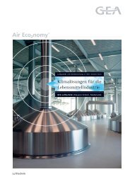
What are EC motors?<br />
EC-motors (= electronically commutated motors) are DC<br />
motors, where the rotor is not performed as a coil, like in<br />
usual AC motors, but consists of a permanent magnet.<br />
Electronic control of the motor enables continuous operation,<br />
where the integrated electronics ensures alternating<br />
magnetic field which adjusts itself to the relevant speed<br />
(refer to Fig. 19). As compared to mechanical commutating<br />
(brushes), there are no moving regulation components<br />
that generate additional losses.<br />
In such a way the motor operates at optimal conditions, resulting<br />
in maximum torque and minimum losses. The efficiency<br />
rate of the EC motors used by <strong>GEA</strong> is twice as high<br />
as the comparable AC motors. The application of this technology<br />
in <strong>GEA</strong> fan coil units makes it possible to achieve<br />
high efficiency rates for fan motors - especially in part-load<br />
mode.<br />
North pole<br />
Regulation Regulation<br />
Coil<br />
Coil<br />
South<br />
South<br />
North pole<br />
Flow direction Flow direction<br />
Fig. 19: Functional description of EC motor<br />
(electr. commutation)<br />
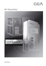
This results in the reduction of electrical power consumption of an EC fan by up to 84%.<br />
Comparison AC/EC fan - <strong>Flex</strong>-<strong>Geko</strong><br />
180<br />
160<br />
Electrical power consumption [W]<br />
140<br />
120<br />
100<br />
80<br />
60<br />
-41%<br />
-79%<br />
-27%<br />
AC fan size 1<br />
AC fan size 8<br />
EC fan size 1<br />
EC fan size 8<br />
40<br />
-84%<br />
20<br />
0<br />
-71%<br />
-59%<br />
0 200 400 600 800 1000 1200 1400 1600 1800 2000<br />
Air volume flow [m³/h]<br />
Fig. 20: Comparison - electrical power consumption EC/AC fan<br />
8 PR-2011-0114-GB • Subject to modifications • Status 10/2011
<strong>GEA</strong> <strong>Flex</strong>-<strong>Geko</strong> <strong>Comfort</strong> <strong>Edition</strong><br />
Unit Description<br />
Keyword Energy Efficiency: EC Technology<br />
Further aspects: – Continuous operation<br />
– Low generation of heat<br />
– Established and usual high motor quality<br />
– Same design for 50 and 60 Hz<br />
Continuous <strong>GEA</strong> MATRIX controls<br />
EC fans featuring continuous operation mode offer a few of benefits:<br />
– Room temperature control is performed with a higher accuracy, because occurring<br />
temperature differences can be addressed with the accordingly adjusted fan speed.<br />
This effect is assisted by using 3-point regulation valves (hydraulic method).<br />
– Variable fan speed control can compensate for fluctuating conditions of heating and<br />
cooling medium. Example: season-related different inlet temperature of heat<br />
generator or fluctuating volume flow rates (hydraulics)<br />
– With standard AC fans the fan speed, which is optimal for room temperature control,<br />
must be adapted to the available fan speed stages which often leads to rapid<br />
increase of motor RPM and thus electrical power consumption.<br />
– With continuous speed regulation - "hard" fan speed changes are eliminated, which<br />
provides additional acoustical comfort.<br />
The <strong>GEA</strong> MATRIX controls uses these features by making the following functions<br />
available, the customer can select between automatic and manual operation:<br />
Automatic mode:<br />
Room temperature control with continuous regulation (1.5-10 V) of a stepless EC fan.<br />
The fan continuously operates within the minimum and maximum air volumes.<br />
Using the display control panel OP50/51 a speed limitation can be activated (mute<br />
function) in order to prevent an acoustic overshoot in automatic mode. This upper RPM<br />
limit can be separately set for each control panel.<br />
As an additional measure to avoid possible on-site acoustical resonance occurrences,<br />
up to three speed ranges can be hidden using MATRIX.PC software.<br />
Manual mode:<br />
OP 50/51 (control panel with display): continuous fan setting using rotary switch<br />
between minimum and maximum air volume flow rate.<br />
OP30/31 and OP44: (speed-stage control panel): 5-speed fan setting with speed<br />
1 = minimum air volume flow rate and speed 5 = maximum air volume flow rate.<br />
Percentage values (regarding maximum air volume flow) for speeds 2-4 are<br />
pre-configured by the factory (default values) and can be changed on site by others<br />
using MATRIX.PC.<br />
PR-2011-0114-GB • Subject to modifications • Status 10/2011 9
Unit Description<br />
Keyword Energy Efficiency: EUROVENT Energy Label<br />
<strong>GEA</strong> <strong>Flex</strong>-<strong>Geko</strong> <strong>Comfort</strong> <strong>Edition</strong><br />
EUROVENT Energy Label<br />
Within the framework of EU regulations (Eco-Design Directive) clear limits will be set<br />
in the future with respect to the energy efficiency of state-of-the-art technological<br />
standards. EUROVENT, as the European Association of Manufacturers of HVAC<br />
equipment, anticipates this development by having published Energy Label for fan coil<br />
units to include 7 energy efficiency classes (A to G) in January 2011.<br />
In this case the energy efficiency is composed of time-weighted relationship between<br />
cooling or heating output and consumed electrical power of the fan.<br />
If fan coil units are equipped with an energy-efficient temperature regulation system<br />
(<strong>GEA</strong> MATRIX) the adjustment of fan speed is performed according to the situationrelated<br />
heating or cooling demand. For the evaluation of energy efficiency - time percentage<br />
of the corresponding active speed stages must be considered. For the<br />
description of time-related conditions EUROVENT uses coefficient A (maximum), B<br />
(medium) and C (minimum speed). These indicators vary, depending on heating or<br />
cooling operation mode.<br />
Fan stage Coefficient Time percentage<br />
Cooling Heating<br />
High (maximum) A 5 % 5 %<br />
Medium B 30 % 25 %<br />
Low (minimum) C 65 % 70 %<br />
The energy efficiency relationship is composed of time-weighted shares and is presented<br />
in the example using the following formulas:<br />
Cooling (FCEER):<br />
•<br />
•<br />
•<br />
A × Q<br />
FCEER<br />
KHighSpeed<br />
+ B×<br />
Q KMediumSpeed<br />
+ C×<br />
Q<br />
= -----------------------------------------------------------------------------------------------------------------------------------------------<br />
KLowSpeed<br />
A×<br />
Pe HighSpeed<br />
+ B×<br />
Pe MediumSpeed<br />
+ C×<br />
QPe LowSpeed<br />
Fan Coil Energy Efficiency Ratio - total cooling capacity<br />
(= Energy efficiency relationship)<br />
Heating (FCCOP):<br />
FCCOP<br />
=<br />
• • •<br />
A×<br />
Q HHighSpeed<br />
+ B×<br />
Q HMediumSpeed<br />
+ C×<br />
Q<br />
-----------------------------------------------------------------------------------------------------------------------------------------------<br />
HLowSpeed<br />
A×<br />
Pe HighSpeed<br />
+ B × Pe MediumSpeed<br />
+ C×<br />
Pe LowSpeed<br />
Fan Coil Coefficient Of Performance<br />
(=Performance coefficient of fan coil unit)<br />
•<br />
with QK = Total cooling capacity<br />
•<br />
mit QH = Heating capacity<br />
mit Pe = Electrical power consumption of fan<br />
Higher numerical value of these indicators mean especially outstanding energy efficiency.<br />
10 PR-2011-0114-GB • Subject to modifications • Status 10/2011
<strong>GEA</strong> <strong>Flex</strong>-<strong>Geko</strong> <strong>Comfort</strong> <strong>Edition</strong><br />
Unit Description<br />
Keyword Energy Efficiency: EUROVENT Energy Label/Optimised Heat Exchanger<br />
For the corresponding energy label the EUROVENT determines the following<br />
classification:<br />
FCEER (Total)<br />
Class Value<br />
A = 185<br />
B = 120<br />
C = 80<br />
D = 55<br />
E = 40<br />
F = 30<br />
G = 0<br />
FCCOP<br />
Class Value<br />
A = 265<br />
B = 160<br />
C = 100<br />
D = 70<br />
E = 50<br />
F = 40<br />
G = 0<br />
Example:<br />
<strong>GEA</strong> <strong>Flex</strong>-<strong>Geko</strong> GF51.UWW1.SE0A1<br />
[unit code for 4-pipe with EC fan]<br />
Cooling (FCEER) *:<br />
FCEER<br />
=<br />
5% × 4, 48 + 30% × 2, 95 + 65% × 2,<br />
04<br />
5% ----------------------------------------------------------------------------------------------------------- =<br />
× 0, 038 + 30% × 0, 010 + 65% × 0,<br />
005<br />
299 ≥ 185 CLASS A<br />
Label<br />
Heating (FCCOP) *:<br />
FCEER<br />
Label<br />
=<br />
5% × 5, 27 + 25% × 3, 61 + 70% × 2,<br />
65<br />
5% ----------------------------------------------------------------------------------------------------------- =<br />
× 0, 038 + 25% × 0, 010 + 70% × 0,<br />
005<br />
371 ≥ 265 CLASS A<br />
*) Cooling, heating and electrical output in [kW] under EUROVENT conditions:<br />
Cooling: air intake 27°C / 47% r.h., chilled water 7 / 12°C<br />
Heating: air intake 20°C, warm water 70 / 60°C<br />
Optimised heat exchangers for low-energy applications<br />
<strong>GEA</strong> <strong>Flex</strong>-<strong>Geko</strong> offers today additional heat exchanger models especially for low-energy<br />
applications, such as heat pumps that are optimised for low heating medium or<br />
high cooling medium temperatures and low mass flows:<br />
– 2-pipe systems: additional capacity size 4 *<br />
– 4-pipe systems: additional capacity size 3 *<br />
*) Only unit models for water, without direct evaporator and/or electric heater<br />
AiD@<br />
Data for all unit types can be calculated using our AiD@ layout software or provided by<br />
our sales representatives.<br />
PR-2011-0114-GB • Subject to modifications • Status 10/2011 11
Recirculating Unit Cooling and Heating<br />
4-Pipe Chilled and Warm Water<br />
Model Sizes 1 to 8<br />
CWP 6/12 °C<br />
t L1 = +27 °C<br />
ϕ 1 = 46 % r.h.<br />
PWW 70/50 °C<br />
t L1 = +20 °C<br />
<strong>GEA</strong> <strong>Flex</strong>-<strong>Geko</strong> <strong>Comfort</strong> <strong>Edition</strong><br />
Model size<br />
Speeds<br />
1<br />
2<br />
3<br />
4<br />
5<br />
6<br />
7<br />
8<br />
++<br />
Air flow rate<br />
Cooling capacity<br />
Capacity stage 1 Capacity stage 2 AC motor EC motor<br />
Pressure drop<br />
Heating capacity<br />
Pressure drop<br />
Cooling capacity<br />
Pressure drop<br />
•<br />
QK Δp K<br />
•<br />
QH Δp H<br />
•<br />
QK Δp K<br />
•<br />
QH Δp H<br />
[m 3 /h] kW kPa kW kPa kW kPa kW kPa dB(A) dB(A) dB(A) dB(A)<br />
Heating capacity<br />
Pressure drop<br />
Sound power<br />
1 145 0.9 6.3 0.6 0.1 1.0 1.3 0.8 0.1 30 21 28 < 20<br />
Plastic terminal box (select<br />
2 215 1.2 10.0 0.9 0.1 1.3 2.3 1.0 0.2 36 28 37 28<br />
sheet steel electric control<br />
3 270 1.4 13.0 1.0 0.2 1.5 3.1 1.2 0.3 42 33 42 33<br />
box with <strong>GEA</strong> MATRIX)<br />
4 345 1.6 16.6 1.1 0.2 1.8 4.4 1.4 0.4 48 39 48 39<br />
5 525 2.0 24.5 1.4 0.4 2.3 6.8 1.7 0.5 58 50 58 50<br />
1 155 1.0 1.9 1.0 0.2 1.2 2.5 1.0 0.3 28 < 20 27 < 20<br />
2 225 1.3 3.2 1.2 0.4 1.6 4.2 1.3 0.4 35 26 36 27<br />
3 280 1.6 4.3 1.4 0.5 1.9 5.7 1.5 0.6 42 33 41 32<br />
4 355 1.8 5.6 1.6 0.6 2.3 8.1 1.8 0.8 46 37 47 38<br />
5 535 2.3 8.7 2.0 0.9 3.0 13.2 2.2 1.1 58 49 58 49<br />
1 275 1.8 6.5 1.7 0.8 1.9 2.5 1.7 0.9 30 21 30 22<br />
2 345 2.1 8.7 1.9 1.0 2.2 3.4 2.0 1.1 35 27 36 27 Speed combination<br />
3 465 2.5 12.2 2.2 1.3 2.9 5.4 2.4 1.6 43 34 43 34<br />
4 665 3.1 17.6 2.7 1.8 3.6 8.3 2.9 2.2 52 44 52 43 1-2-3 + A<br />
5 880 3.5 22.9 3.1 2.3 4.3 11.4 3.3 2.9 59 51 59 50 2-3-4 + B<br />
1 285 2.0 9.2 1.9 1.2 2.2 3.7 2.0 1.3 29 20 29 20 3-4-5 + C<br />
2 355 2.3 12.4 2.2 1.5 2.6 5.0 2.2 1.7 35 26 34 25 1-3-5 + E<br />
3 485 2.9 18.1 2.6 2.1 3.3 7.8 2.7 2.4 41 32 41 33 1-2-3-4-5 + H<br />
4 715 3.6 27.5 3.2 3.0 4.3 13.0 3.4 3.6 51 42 51 42 Min..Max (EC motor) F<br />
5 980 4.3 37.2 3.7 3.9 5.2 18.6 4.0 4.8 58 50 59 50<br />
1 295 2.0 3.8 2.1 1.7 2.4 4.9 2.1 1.8 28 20 28
<strong>GEA</strong> <strong>Flex</strong>-<strong>Geko</strong> <strong>Comfort</strong> <strong>Edition</strong><br />
Accessories and Valves<br />
Recirculating Unit Cooling and Heating<br />
4-Pipe Chilled and Warm Water, Sizes 1 to 8<br />
Accessories<br />
Arrangement/<br />
installation<br />
Variant/<br />
unit casing<br />
vertical wall/<br />
horizontal ceiling<br />
Vertical wall<br />
vertical wall/<br />
horizontal ceiling<br />
Vertical wall<br />
vertical wall/<br />
horizontal ceiling;<br />
with<br />
unit foot cover **<br />
Suitable for<br />
air flow designation<br />
A<br />
B<br />
C<br />
D<br />
A<br />
Discharge<br />
grille<br />
Plastic<br />
adjustable<br />
Aluminium<br />
rigid<br />
Plastic<br />
adjustable<br />
Plastic<br />
adjustable<br />
Aluminium<br />
rigid<br />
Plastic<br />
adjustable<br />
Plastic<br />
adjustable<br />
Aluminium<br />
rigid<br />
Code<br />
C 012<br />
C 013<br />
C 022<br />
C 032<br />
C 033<br />
C 042<br />
C 052<br />
C 053<br />
Variant Design Code<br />
Discharge plenum<br />
primary air connection DN100<br />
insulated A 022<br />
Discharge plenum<br />
with round fitting DN200<br />
insulated A 042<br />
Discharge bend insulated A 062<br />
<strong>Flex</strong>ible discharge connection A 112<br />
Discharge sound absorber connection A 212<br />
<strong>GEA</strong> Drive – motorised<br />
regulated discharge profile ***<br />
Air intake plenum with<br />
primary air connection DN 125<br />
Air intake plenum with<br />
round connection DN 200<br />
left<br />
412<br />
A<br />
right 422<br />
not insulated A 011<br />
not insulated A 031<br />
vertical wall;<br />
with<br />
unit foot cover **<br />
vertical wall/horizontal<br />
ceiling; with<br />
unit foot cover and<br />
intake front grille **<br />
B<br />
A<br />
Plastic<br />
adjustable<br />
Plastic<br />
adjustable<br />
Aluminium<br />
rigid<br />
C 062<br />
C 072<br />
C 073<br />
Air intake bend not insulated A 051<br />
Intake flexible connection<br />
(transition piece required)<br />
Transition piece for intake flexible connection,<br />
telescope and sound absorber connection<br />
A 111<br />
A 131<br />
vertical wall, with<br />
unit foot cover and<br />
intake front grille **<br />
horizontal ceiling;<br />
closed rear side<br />
B<br />
C<br />
Plastic<br />
adjustable<br />
Plastic<br />
adjustable<br />
Aluminium<br />
rigid<br />
C 082<br />
C 132<br />
C 133<br />
Intake telescope connection<br />
(transition piece required)<br />
not insulated A 151<br />
Intake sound absorber connection for<br />
A 211<br />
recirculating air unit (transition piece required)<br />
Seal cap for round<br />
insulated A 713<br />
fitting, DN 200 *<br />
** Unit feet ZGF.0A913 required<br />
vertical stand-alone<br />
installation<br />
closed on rear side<br />
C<br />
Plastic<br />
adjustable<br />
Aluminium<br />
rigid<br />
C 232<br />
C 233<br />
Unit feet for circulating air units * A 913<br />
Spare filter (5 pieces)<br />
G1<br />
813<br />
G2 A 823<br />
G3 833<br />
Sizes 1 to 8<br />
* 0, if irrespective<br />
of size<br />
Order code<br />
Z G F •<br />
*** NOTE!<br />
<strong>GEA</strong> Drive only possible witht<br />
<strong>GEA</strong> unit casing!<br />
Valves<br />
MATRIX 500<br />
MATRIX 2000<br />
MATRIX 3000/4000<br />
Terminal box<br />
Actuator Operating voltage/circuit<br />
• • • • 2-point 230 V AC 2) T<br />
• • • O/C<br />
1), 2)<br />
24 V AC Q<br />
3-point 230 V AC R<br />
• • O/Stop/ 24 V AC 1) N<br />
C<br />
230 V AC + 2 Contacts C<br />
•<br />
Continu-<br />
Connection/shut-off<br />
Inlet/outlet with external thread 0<br />
Inlet/outlet with solder fitting 1<br />
Inlet/outlet + ball cock with external thread 2<br />
Inlet/outlet + ball cock with solder fitting 3<br />
Inlet + ball cock/<br />
outlet + shut off valve with external thread<br />
4<br />
Inlet + ball cock/<br />
outlet + shut off valve with solder fitting<br />
5<br />
Heat circuit<br />
Cool circuit<br />
2 3<br />
k vs -values<br />
Cooling/Heating<br />
0.25 ≡ 03<br />
0.40 ≡ 04<br />
0.63 ≡ 06<br />
1.00 ≡ 10<br />
1.60 2) ≡ 16<br />
2.50 2) ≡ 25<br />
4.00 ≡ 40<br />
Coil connection<br />
left<br />
right<br />
L<br />
R<br />
ous 0/2 ... 10 V = 24 V AC 1) S V G F • •<br />
1) 24 V-transformer by others<br />
2) k vs -values for open/close actuators<br />
(T,Q) only k vs 1.6 and 2.5 possible<br />
Order code<br />
Cooling circuit<br />
Heating circuit<br />
PR-2011-0114-GB • Subject to modifications • Status 10/2011 13
on<br />
func<br />
send<br />
%<br />
Controls<br />
Recirculating Unit Cooling and Heating<br />
4-Pipe Chilled and Warm Water, Sizes 1 to 8<br />
<strong>GEA</strong> <strong>Flex</strong>-<strong>Geko</strong> <strong>Comfort</strong> <strong>Edition</strong><br />
<strong>GEA</strong> MATRIX 500/2000<br />
System features MATRIX 500/2000 (not for EC motor):<br />
MATRIX OP5C<br />
– Temperature assignment: 10 ... 30 °C<br />
– Manual assignment of speed stage<br />
– Limitable setting range<br />
– Change-over between normal/economy mode on control panel<br />
– Indoor temperature measurement using control panel<br />
– External indoor temperature sensor can be connected<br />
– Valve control (2-point)<br />
– Temperature control via fan on/off and valve(s)<br />
– Status messages using LED<br />
– Group control<br />
– Group switch-off switch-off in case of fault<br />
– Motor temperature monitoring<br />
(TC required)<br />
Additional features MATRIX 2000:<br />
Control panel for MATRIX 500<br />
– Pure white casing, protection type IP20<br />
– Setpoint temperature setting<br />
– Speed stage selection switch 0-A (continuous)-1-2-3<br />
– Economy mode button<br />
– LEDs for operation/fault/ext.control<br />
– Integrated room temperature sensor<br />
MATRIX OP21C<br />
Control panel for MATRIX 2000,<br />
as control panel OP5C, but with additional:<br />
– Speed stage selection switch 0-A (Auto)-1-2-3<br />
T<br />
A<br />
– Extended temperature assignment: 7 ... 40 °C<br />
(default 10 ... 30 °C)<br />
– Temperature control via fan speed change and valve(s)<br />
– Capable of networking<br />
<strong>GEA</strong> MATRIX 3000/4000<br />
System features MATRIX 3000:<br />
– Temperature assignment: 7 ... 40 °C (default 10 ... 30 °C)<br />
– Speed (stage) assignment<br />
– Limitable setting range<br />
– Change-over between normal/economy mode on control<br />
panel<br />
– Input for change-over between normal/economy mode or<br />
unit OFF with frost protection<br />
– Indoor temperature measurement using control panel<br />
– External indoor temperature sensor can be connected<br />
– Valve control (2x2 or 2x3 point)<br />
– Temperature control via fan and/or valve(s)<br />
– Room frost protection<br />
– Status messages using LED<br />
– Status and fault signals using floating change-over contacts<br />
– Unit individual and group control<br />
– Isolation of individual units in case of fault<br />
– Motor temperature monitoring<br />
(with speed stage motors TC required)<br />
– Capable of networking<br />
Additional features MATRIX 4000:<br />
MATRIX OP30C<br />
Control panel for MATRIX 3000/4000<br />
– Pure white casing, protection type IP20<br />
– Setpoint temperature setting<br />
– Speed-stage selection switch 0-A(Auto)-1-2-3-4-5<br />
(depends on motor type)<br />
– LEDs for operation/fault/ext.control<br />
– Integrated room temperature sensor<br />
MATRIX OP31C<br />
Like control panel OP30C, but with additional:<br />
– Normal/economy mode buttons<br />
MATRIX OP44C<br />
Like control panel OP31C, but with additional button for:<br />
– Change-over recirculating / mixed air mode<br />
– Change-over heating/cooling/automatic mode<br />
B<br />
C<br />
D<br />
– Summer / winter compensation<br />
– Noiseless valve control<br />
– Cool and/or heat request via volt-free contacts (related to<br />
water circuit)<br />
– Stand alone unit control<br />
– Inputs for operating mode:<br />
Normal mode<br />
Economy mode<br />
Autonomous mode<br />
Unit OFF<br />
MATRIX OP50C<br />
Control panel for MATRIX 3000/4000<br />
– Pure white casing, protection type IP20<br />
– Menu-guided controls using rotation navigator<br />
– LCD clear text display<br />
– Status messages using pictograms<br />
– Integrated room temperature sensor<br />
– Continuous speed regulation<br />
(only together with EC motor)<br />
MATRIX OP51C<br />
100 R E 14:08<br />
21 . 5 ° C<br />
E<br />
F<br />
Like control panel OP50C, but with additional:<br />
– Integrated weekly clock timer with<br />
a holiday and special days programme<br />
MATRIX.IR<br />
Infrared remote control for<br />
control system MATRIX 3000/4000<br />
– Black casing, RAL 9004<br />
– LCD display approx. 45x30 mm<br />
– Function as in OP44C (without status, fault and external<br />
control signals, no integrated indoor temp. sensor)<br />
– Maximum range 20 m<br />
– Speed selection 0-A-1-2-3<br />
off<br />
- +<br />
N<br />
14 PR-2011-0114-GB • Subject to modifications • Status 10/2011
<strong>GEA</strong> <strong>Flex</strong>-<strong>Geko</strong> <strong>Comfort</strong> <strong>Edition</strong><br />
Controls<br />
Recirculating Unit Cooling and Heating<br />
4-Pipe Chilled and Warm Water, Sizes 1 to 8<br />
With controller type:<br />
D0 = 7x2x0.8 J-Y(ST)Y<br />
D2 = 5x2x0.8 J-Y(ST)Y<br />
Master<br />
unit<br />
With controller type:<br />
D0 = 7x2x0.8 J-Y(ST)Y<br />
D2 = 4x2x0.8 J-Y(ST)Y<br />
Slave units<br />
D2: 1-15<br />
D0: 1-3<br />
3x1,5 mm 2 NYM<br />
3x1.5 mm 2 NYM<br />
Cooling/heat.medium<br />
230 V ~<br />
50 Hz<br />
Without return air sensor * 0<br />
With return air sensor * 5<br />
Enclosed control panel<br />
Integrated control panel<br />
A<br />
B<br />
Order code MATRIX 500<br />
D 0 • 5 1 • T<br />
D 0 • 5 0 1 • Z D<br />
Order code MATRIX 2000<br />
D 2 • 2 1 • A<br />
D 2 • 2 0 1 • Z D<br />
e.g. 2x2x0.5 Helukabel<br />
Master<br />
unit<br />
With controller type:<br />
D2 = 4x2x0.8 J-Y(ST)Y<br />
D3/4 = e.g. 1x2x0.5 Helukabel<br />
Slave units<br />
1-15<br />
3x1,5 mm 2 NYM<br />
3x1.5 mm 2 NYM<br />
Cooling/heat.medium<br />
230 V ~<br />
50 Hz<br />
Speed<br />
(EC motor)<br />
Speed stages<br />
(AC motor)<br />
Stand alone unit<br />
control with operating<br />
and alarm messaging<br />
Group regulation<br />
with status and<br />
alarm signals<br />
Input unit OFF<br />
with room frost<br />
protection<br />
Input<br />
economy contact<br />
Supply temperature<br />
limitation<br />
Noiseless<br />
valve control<br />
Contact heat and<br />
cool request<br />
<strong>GEA</strong> Drive<br />
Connection<br />
external sensor<br />
Continuous<br />
up to<br />
3<br />
spee<br />
d<br />
up to<br />
5<br />
spee<br />
d<br />
• • 3 1 2 0 1<br />
• • 3 2 2 0 1<br />
• • 3 1 3 1<br />
• • 3 2 3 2<br />
• • • 3 3 3 3<br />
• • • 3 4 3 4<br />
• • • • 4 1 4 1<br />
• • • • 4 2 4 2<br />
• • • • • 4 3 4 3<br />
• • • • • 4 4 4 4<br />
• • • • • • 4 5 4 5<br />
• • • • • • • 4 6 4 6<br />
• • • • • • • 4 6 4 6<br />
Without return air sensor * 0<br />
With return air sensor * 5<br />
Control panel<br />
Enclosed control panel<br />
Integrated control panel<br />
A<br />
B<br />
Order code<br />
D • 2 • D • 2 • Z D<br />
* Alternative room temperature sensor (see page 99)<br />
Master unit<br />
Slave unit<br />
PR-2011-0114-GB • Subject to modifications • Status 10/2011 15
Recirculating Unit Cooling and Heating<br />
2-Pipe Chilled Water and Electric Heating<br />
Model Sizes 1 to 8<br />
CWP 6/12 °C<br />
t L1 = +27 °C<br />
j 1 = 46 % r.h.<br />
Electric heater<br />
230V~N/P/E<br />
50Hz<br />
<strong>GEA</strong> <strong>Flex</strong>-<strong>Geko</strong> <strong>Comfort</strong> <strong>Edition</strong><br />
Model size<br />
Speeds<br />
1<br />
2<br />
3<br />
4<br />
5<br />
6<br />
7<br />
8<br />
++<br />
Air flow rate<br />
Cooling capacity<br />
Capacity stage 1 Capacity stage 2 5-speed motor<br />
Pressure drop<br />
AEX 1) Speed L<br />
AEX 1) Speed M<br />
Cooling capacity<br />
Pressure drop<br />
AEX 1) Speed L<br />
AEX 1) Speed M<br />
•<br />
• • • • •<br />
QK Δp K QH QH QK Δp K QH QH<br />
Sound power<br />
Sound pressure *<br />
3-speed motor<br />
w.series resistor<br />
[m 3 /h] kW kPa kW kW kW kPa kW kW dB(A) dB(A) dB(A) dB(A) 1) Auxiliary electric heating<br />
1 – – – – – – – – – – – – –<br />
2 220 1.2 9.2 0.87 - 1.4 3.4 0.87 – 36 28 38 30<br />
3 270 1.4 11.4 0.87 0.87 1.7 4.6 0.87 0.87 42 33 45 36<br />
4 350 1.6 14.9 1.74 0.87 1.9 6.2 1.74 0.87 48 39 51 43<br />
5 530 2.0 21.9 - 1.74 2.5 9.9 – 1.74 58 50 61 52<br />
1 – – – – – – – – – – – – –<br />
2 230 1.5 17.7 1.27 – 1.7 6.2 1.27 – 35 26 39 30<br />
3 280 1.7 22.1 1.27 1.27 2.0 8.3 1.27 1.27 42 33 46 37<br />
4 360 2.0 29.1 2.54 1.27 2.4 11.1 2.54 1.27 46 37 51 42<br />
5 540 – – – 2.54 3.1 18.4 – 2.54 58 49 60 51<br />
1 – – – – – – – – – – – – –<br />
2 350 2.0 7.2 1.67 – 2.5 4.9 1.67 – 35 27 39 31<br />
3 470 2.4 10.0 1.67 1.67 3.1 7.4 1.67 1.67 43 34 45 36<br />
4 670 3.0 14.7 3.34 1.67 3.9 11.2 3.34 1.67 52 44 55 46<br />
5 890 3.4 19.1 – 3.34 4.5 15.1 – 3.34 59 51 62 53<br />
1 – – – – – – – – – – – – –<br />
2 360 2.3 10.4 1.95 – 2.8 6.9 1.95 – 35 26 39 30<br />
3 490 2.8 15.0 1.95 1.95 3.5 10.5 1.95 1.95 41 32 45 37<br />
4 720 3.5 22.6 3.9 1.95 4.5 17.2 3.9 1.95 51 42 55 46<br />
5 990 4.1 30.8 – 3.9 5.5 24.4 – 3.9 58 50 63 54<br />
1 – – – – – – – – – – – – –<br />
2 370 2.5 13.9 2.03 – 3.0 9.3 2.03 – 34 25 38 29<br />
3 520 3.2 21.3 2.03 2.03 3.9 14.7 2.03 2.03 42 34 46 37 Metal sheet electric control box<br />
4 740 3.9 31.5 4.06 2.03 5.0 23.0 4.06 2.03 51 42 55 46<br />
5 1010 4.7 43.0 – 4.06 6.1 33.4 – 4.06 59 51 62 53<br />
1 – – – – – – – – – – – – –<br />
2 560 3.1 3.9 2.07 – 3.8 2.6 2.07 – 39 31 41 32<br />
3 750 3.8 5.4 2.07 2.07 4.8 4.0 2.07 2.07 46 38 48 39<br />
4 990 4.4 7.3 4.14 2.07 5.7 5.6 4.14 2.07 55 47 56 47<br />
5 1310 5.2 9.8 – 4.14 6.8 7.6 – 4.14 62 54 62 53<br />
1 – – – – – – – – – – – – –<br />
2 580 3.5 5.0 2.07 – 4.2 3.4 2.07 – 38 30 41 33<br />
3 770 4.2 7.1 2.07 2.07 5.2 5.0 2.07 2.07 46 38 48 40<br />
4 1030 5.0 9.8 4.14 2.07 6.4 7.3 4.14 2.07 54 45 56 47<br />
5 1420 5.9 13.4 – 4.14 7.8 10.6 – 4.14 62 53 63 54<br />
Sound power<br />
Sound pressure *<br />
with terminal strip or for integ.<br />
controls<br />
1 – – – – – – – – – – – – – Speed combination<br />
2 690 4.2 7.7 2.07 – 5.0 5.1 2.07 – 38 29 40 31<br />
3 970 5.2 11.3 2.07 2.07 6.4 7.9 2.07 2.07 46 37 48 40 2-3-4 L<br />
4 1380 6.3 16.3 4.14 2.07 8.2 12.6 4.14 2.07 55 46 58 49 3-4-5 M<br />
5 1820 7.3 21.1 – 4.14 9.6 16.9 – 4.14 61 53 64 55<br />
CS 1 CS 2<br />
Motor thermal contact<br />
5-speed<br />
motor<br />
3-speed<br />
motor with<br />
series resistor<br />
TC integr. 0<br />
TC led out 1<br />
TC integr. 8<br />
TC led out 9<br />
1 left<br />
2 right<br />
3 left<br />
4 right<br />
Wall<br />
Ceiling<br />
Medium<br />
connect.***<br />
0 with drainage<br />
1 with condensate pump<br />
Condensate line<br />
A<br />
C<br />
Recirculating air / - supply air /<br />
Recirculating air / - supply air /<br />
Air<br />
flow +++<br />
1 G1 mat filter<br />
2 G2 mat filter<br />
Filter<br />
Order code G F • U W E •<br />
* Ambient conditions see page 70 Acoustics<br />
*** Front connection side, facing discharge<br />
++ Air volume flow CS 1 and filter class G1<br />
+++ Definition of air flow wall/ceiling see page 74 Fig. 28<br />
16 PR-2011-0114-GB • Subject to modifications • Status 10/2011
<strong>GEA</strong> <strong>Flex</strong>-<strong>Geko</strong> <strong>Comfort</strong> <strong>Edition</strong><br />
Accessories/Valves<br />
Recirculating Unit Cooling and Heating<br />
2-Pipe Chilled Water and E-Heating, Model Sizes 1 to 8<br />
Accessories<br />
Arrangement/<br />
installation<br />
Variant/<br />
unit casing<br />
vertical wall/<br />
horizontal ceiling<br />
Suitable for<br />
air flow designation<br />
A<br />
Discharge<br />
grille<br />
Aluminium<br />
rigid<br />
Code<br />
C 013<br />
Variant Design Code<br />
Air intake plenum with<br />
primary air connection DN 125<br />
not insulated A 011<br />
Air intake bend not insulated A 051<br />
vertical wall/<br />
horizontal ceiling<br />
C<br />
Aluminium<br />
rigid<br />
C 033<br />
Transition piece for intake telescopic connection A 131<br />
vertical wall/<br />
horizontal ceiling;<br />
with unit foot cover **<br />
A<br />
Aluminium<br />
rigid<br />
C 053<br />
Intake telescope connection<br />
(transition piece required)<br />
not insulated A 151<br />
vertical wall/horizontal<br />
ceiling; with unit<br />
foot cover and intake<br />
front grille **<br />
horizontal ceiling;<br />
closed on rear side<br />
A<br />
C<br />
Aluminium<br />
rigid<br />
Aluminium<br />
rigid<br />
C 073<br />
C 133<br />
Unit feet for circulating air units * A 913<br />
Spare filter (5 pieces)<br />
G1<br />
813<br />
A<br />
G2 823<br />
vertical stand-alone<br />
installation<br />
closed on rear side<br />
C<br />
Aluminium<br />
rigid<br />
C 233<br />
** Unit feet ZGF.0A913 required<br />
Sizes 1 to 8<br />
* 0, if irrespective<br />
of size<br />
Order code<br />
Z G F •<br />
Valves<br />
MATRIX 500<br />
MATRIX 2000<br />
MATRIX 3000/4000<br />
Terminal box<br />
Actuator Operating voltage/circuit<br />
• • 2-point 230 V AC 2) T<br />
• • O/C<br />
1), 2)<br />
24 V AC Q<br />
• •<br />
230 V AC R<br />
3-point<br />
O/Stop/ 24 V AC 1) N<br />
230 V AC + 2 contacts C<br />
• Contin. 0/2 ... 10 V = 24 V AC 1) S<br />
Connection/shut-off<br />
Inlet/outlet with external thread 0<br />
Inlet/outlet with solder fitting 1<br />
Inlet/outlet + ball cock with external thread 2<br />
Inlet/outlet + ball cock with solder fitting 3<br />
Inlet + ball cock/<br />
outlet + shut off valve with external thread<br />
4<br />
Inlet + ball cock/<br />
outlet + shut off valve with solder fitting<br />
5<br />
Cool circuit<br />
2 3<br />
k vs -values<br />
Cooling<br />
0.25 ≡ 03<br />
0.40 ≡ 04<br />
0.63 ≡ 06<br />
1.00 ≡ 10<br />
1.60 2) ≡ 16<br />
2.50 2) ≡ 25<br />
4.00 ≡ 40<br />
Coil Connection<br />
left L<br />
right R<br />
1) 24 V-transformer to be provided by<br />
others<br />
2) kvs-values for open/close actuators<br />
(T,Q) only kvs 1.6 and 2.5 possible<br />
Order code<br />
V G F • •<br />
Cooling circuit<br />
PR-2011-0114-GB • Subject to modifications • Status 10/2011 17
on<br />
func<br />
send<br />
%<br />
Controls<br />
Recirculating Unit Cooling and Heating<br />
2-Pipe Chilled Water and E-Heating, Model Sizes 1 to 8<br />
<strong>GEA</strong> <strong>Flex</strong>-<strong>Geko</strong> <strong>Comfort</strong> <strong>Edition</strong><br />
<strong>GEA</strong> MATRIX 500/2000<br />
not applicable<br />
<strong>GEA</strong> MATRIX 4000<br />
System features MATRIX 4000:<br />
– Temperature assignment: 7 ... 40 °C<br />
(default 10 ... 30 °C)<br />
– Assignment of speed stage<br />
– Limitable setting range<br />
– Change-over between normal/economy mode on<br />
control panel<br />
– Input for change-over between normal/economy<br />
mode or unit OFF with frost protection<br />
– Indoor temperature measurement using control<br />
panel<br />
– External indoor temperature sensor can be<br />
connected<br />
– Valve control (2 or 3 point)<br />
– Temperature control via fan and/or valve<br />
– Room frost protection<br />
– Status messages using LED<br />
– Status and alarm signal via volt free change-over<br />
contacts<br />
– Unit individual and group control<br />
– Isolation of individual units in case of fault<br />
– Motor temperature monitoring<br />
(TC required)<br />
– Capable of networking<br />
– Summer / winter compensation<br />
– Noiseless valve control<br />
– Cool request via volt free contact (related to water<br />
circuit)<br />
– Stand alone unit control<br />
– Inputs for operating mode:<br />
Normal mode<br />
Economy mode<br />
Autonomous mode<br />
Unit OFF<br />
– Regulation of multi-stage electrical heating with<br />
disconnection in case of over-temperature<br />
MATRIX OP30C<br />
Control panel for MATRIX 4000<br />
– Pure white casing, protection type IP20<br />
– Setpoint temperature setting<br />
– Speed stage selection switch 0-A (Auto)-1-2-3<br />
– LEDs for operation/fault/ext.control<br />
– Integrated room temperature sensor<br />
MATRIX OP31C<br />
Like control panel OP30C, but with additional:<br />
– Normal/economy mode buttons<br />
MATRIX OP44C<br />
Like control panel OP31C, but with additional button<br />
for:<br />
– Change-over recirculating / mixed air mode<br />
– Change-over heating/cooling/automatic mode<br />
MATRIX OP50C<br />
Control panel for MATRIX 4000<br />
– Pure white casing, protection type IP20<br />
– Menu-guided controls using rotation navigator<br />
– LCD clear text display<br />
– Status messages using pictograms<br />
– Integrated room temperature sensor<br />
MATRIX OP51C<br />
Like control panel OP50C, but with additional:<br />
– Integrated weekly clock timer with holiday and<br />
special days programme<br />
100 R E 14:08<br />
21 . 5 ° C<br />
B<br />
C<br />
D<br />
E<br />
F<br />
MATRIX.IR<br />
Infrared remote control for control system<br />
MATRIX 4000<br />
– Black casing, RAL 9004<br />
– LCD display approx. 45x30 mm<br />
– Function as in OP44C (without status,<br />
alarm and external control signals, no integrated<br />
room temperature sensor)<br />
– Maximum range 20 m<br />
off<br />
- +<br />
N<br />
18 PR-2011-0114-GB • Subject to modifications • Status 10/2011
<strong>GEA</strong> <strong>Flex</strong>-<strong>Geko</strong> <strong>Comfort</strong> <strong>Edition</strong><br />
Controls<br />
Recirculating Unit Cooling and Heating<br />
2-Pipe Chilled Water and E-Heating, Model Sizes 1 to 8<br />
Master<br />
unit<br />
230 V~<br />
50 Hz<br />
Slave units<br />
1-15<br />
230 V~<br />
50 Hz<br />
2x2x0.5 Helukabel<br />
e.g. 1x2x0.5 Helukabel<br />
3x1.5 mm 2 NYM<br />
3x1.5 mm 2 NYM<br />
Cooling medium<br />
230 V ~<br />
50 Hz<br />
3x2.5 mm 2 NYM<br />
3x2.5 mm 2 NYM<br />
230 V ~<br />
50 Hz<br />
230 V ~<br />
50 Hz<br />
Speeds<br />
Stand alone unit<br />
control with signasl:<br />
operating and alarm<br />
Input unit OFF<br />
with room frost<br />
protection<br />
Input<br />
economy contact<br />
Noiseless<br />
valve control<br />
Contact heat and<br />
cool request<br />
Connection<br />
external sensor<br />
up to<br />
3 speed<br />
• • • • 1 1<br />
• • • • 2 2<br />
• • • • • • 5 5<br />
Without return air sensor * 2<br />
With return air sensor * 7<br />
Control panel<br />
Enclosed control panel<br />
Integrated control panel<br />
A<br />
B<br />
Order code<br />
D 4 • 2 • D 4 • 2 • Z D<br />
* Alternatively room temperature sensor (see page 99)<br />
Master unit<br />
Slave unit<br />
PR-2011-0114-GB • Subject to modifications • Status 10/2011 19
Recirculating Unit Cooling and Heating<br />
Direct Evaporator and 2-Pipe Warm Water<br />
Model Sizes 1 to 8<br />
t o = 10 °C<br />
t L1 = +27 °C<br />
j 1 = 46 % r.h.<br />
Refrigerant:<br />
R410A<br />
PWW 70/50 °C<br />
t L1 = +20 °C<br />
<strong>GEA</strong> <strong>Flex</strong>-<strong>Geko</strong> <strong>Comfort</strong> <strong>Edition</strong><br />
Model size<br />
1<br />
2<br />
3<br />
4<br />
5<br />
6<br />
7<br />
8<br />
Speeds<br />
++<br />
Air flow rate<br />
Cooling capacity<br />
Capacity stage 1<br />
Heating capacity<br />
Pressure drop<br />
Sound power<br />
5-speed motor<br />
Sound pressure *<br />
3-speed motor<br />
with series resistor<br />
•<br />
QK<br />
•<br />
QH Δp H<br />
[m 3 /h] kW kW kPa dB(A) dB(A) dB(A) dB(A)<br />
1 – – – – – – – –<br />
2 – – – – – – – –<br />
3 270 1.0 1.0 0.2 42 33 45 36<br />
4 345 1.1 1.1 0.2 48 39 51 43<br />
5 525 1.3 1.4 0.4 58 50 61 52<br />
1 – – – – – – – –<br />
2 – – – – – – – –<br />
3 280 1.1 1.4 0.5 42 33 46 37<br />
4 355 1.3 1.6 0.6 46 37 51 42<br />
5 535 1.6 2.0 0.9 58 49 60 51<br />
1 – – – – – – – –<br />
2 – – – – – – – –<br />
3 465 1.8 2.2 1.3 43 34 45 36<br />
4 665 2.2 2.7 1.8 52 44 55 46<br />
5 880 2.6 3.1 2.3 59 51 62 53<br />
1 – – – – – – – –<br />
2 – – – – – – – –<br />
3 485 1.9 2.6 2.1 41 32 45 37<br />
4 715 2.4 3.2 3.0 51 42 55 46<br />
5 980 2.7 3.7 3.9 58 50 63 54<br />
1 – – – – – – – –<br />
2 – – – – – – – –<br />
3 515 2.1 3.0 3.0 42 34 46 37 Metal sheet electric control box<br />
4 735 2.6 3.6 4.3 51 42 55 46<br />
5 1000 3.0 4.2 5.7 59 51 62 53<br />
1 – – – – – – – –<br />
2 – – – – – – – –<br />
3 745 2.8 4.0 5.7 46 38 48 39<br />
4 980 3.3 4.6 7.5 55 47 56 47<br />
5 1295 3.9 5.3 9.5 62 54 62 53<br />
1 – – – – – – – –<br />
2 – – – – – – – –<br />
Sound power<br />
Sound pressure *<br />
with terminal strip or for integ.<br />
Controls<br />
3 765 3.1 4.3 7.4 46 38 48 40<br />
4 1020 3.8 5.1 9.9 54 45 56 47<br />
5 1405 4.6 5.9 13.0 62 53 63 54 Speed combination<br />
1 – – – – – – – –<br />
2 – – – – – – – – 3-4-5 M<br />
3 955 3.5 5.2 11.4 46 37 48 40<br />
4 1365 4.3 6.3 16.0 55 46 58 49<br />
5 1800 4.9 7.2 20.1 61 53 64 55<br />
CS 1<br />
Motor thermal contact<br />
5-speed<br />
motor<br />
3-speed<br />
motor with<br />
series resistor<br />
TC integr. 0<br />
TC led out 1<br />
TC integr. 8<br />
TC led out 9<br />
1 left<br />
2 right<br />
3 left<br />
4 right<br />
0 with drainage<br />
1 with condensate pump<br />
A<br />
Wall<br />
Ceiling<br />
Recirculating air / - Supply air /<br />
Medium<br />
connect.***<br />
Condensate line<br />
B<br />
C<br />
D<br />
Recirculating air / - Supply air /**<br />
Recirculating air / - Supply air /<br />
Recirculating air / - Supply air/<br />
Air flow +++<br />
Order code G F 1 • U D W • M<br />
1 G1 mat filter<br />
2 G2 mat filter<br />
* Ambient conditions see page 70 Acoustics<br />
** Only wall units<br />
*** Front connection side, facing discharge<br />
** Air volume flow for CS 1 and filter class G1<br />
+++ Definition of air flow wall/ceiling see page 74 Fig. 28<br />
Filter<br />
20 PR-2011-0114-GB • Subject to modifications • Status 10/2011
<strong>GEA</strong> <strong>Flex</strong>-<strong>Geko</strong> <strong>Comfort</strong> <strong>Edition</strong><br />
Accessories/Valves<br />
Recirculating Unit Cooling and Heating<br />
DX Evaporator and 2-Pipe Warm Water, Model Sizes 1 to 8<br />
Accessories<br />
Arrangement/<br />
installation<br />
Variant/<br />
unit casing<br />
vertical wall/<br />
horizontal ceiling<br />
Suitable for<br />
air flow<br />
designation<br />
A<br />
Discharge<br />
grille<br />
Plastic<br />
adjustable<br />
Aluminium<br />
rigid<br />
Code<br />
C 012<br />
C 013<br />
Variant Design Code<br />
Discharge plenum<br />
primary air connection DN100<br />
insulated A 022<br />
Discharge bend insulated A 062<br />
Vertical wall<br />
vertical wall/<br />
horizontal ceiling<br />
B<br />
C<br />
Plastic<br />
adjustable<br />
Plastic<br />
adjustable<br />
Aluminium<br />
rigid<br />
C 022<br />
C 032<br />
C 033<br />
<strong>Flex</strong>ible discharge connection A 112<br />
<strong>GEA</strong> Drive – motorised<br />
regulated discharge profile ***<br />
Air intake plenum with<br />
primary air connection DN 125<br />
left<br />
412<br />
A<br />
right 422<br />
not insulated A 011<br />
Vertical wall<br />
vertical wall/<br />
horizontal ceiling;<br />
with<br />
unit foot cover **<br />
D<br />
A<br />
Plastic<br />
adjustable<br />
Plastic<br />
adjustable<br />
Aluminium<br />
rigid<br />
C 042<br />
C 052<br />
C 053<br />
Air intake bend not insulated A 051<br />
Intake flexible connection<br />
(transition piece required)<br />
Transition piece for intake flexible connection,<br />
telescopic connection<br />
A 111<br />
A 131<br />
vertical wall;<br />
with<br />
unit foot cover **<br />
B<br />
Plastic<br />
adjustable<br />
C 062<br />
Intake telescope connection<br />
(transition piece required)<br />
not insulated A 151<br />
vertical wall/horizontal<br />
ceiling; with<br />
unit foot cover and<br />
intake front grille **<br />
vertical wall, with<br />
unit foot cover and<br />
intake front grille **<br />
A<br />
B<br />
Plastic<br />
adjustable<br />
Aluminium<br />
rigid<br />
Plastic<br />
adjustable<br />
C 072<br />
C 073<br />
C 082<br />
Unit feet for circulating air units * A 913<br />
Spare filter (5 pieces)<br />
G1<br />
813<br />
A<br />
G2 823<br />
horizontal ceiling;<br />
closed rear side<br />
C<br />
Plastic<br />
adjustable<br />
Aluminium<br />
rigid<br />
C 132<br />
C 133<br />
vertical stand-alone<br />
installation<br />
closed on rear side<br />
C<br />
Plastic<br />
adjustable<br />
Aluminium<br />
rigid<br />
C 232<br />
C 233<br />
** Unit feet ZGF.0A913 required<br />
Sizes 1 to 8<br />
* 0, if irrespective<br />
of size<br />
Order code<br />
Z G F •<br />
*** Note!<br />
<strong>GEA</strong> Drive only together<br />
with <strong>GEA</strong> unit casing!<br />
Valves<br />
MATRIX 500<br />
MATRIX 2000<br />
MATRIX 3000/4000<br />
Terminal box<br />
Actuator<br />
Operating voltage/circuit<br />
• • 2-point 230 V AC 2) T<br />
open/<br />
• • close 24 V AC 1), 2) Q<br />
• •<br />
3-point 230 V AC R<br />
open/<br />
stop/<br />
24 V AC 1) N<br />
close 230 V AC + 2 contacts C<br />
• Contin. 0/2 ... 10 V = 24 V AC 1) S<br />
DX connection via expansion valve 3) 0<br />
Expansion valve R410 A 3)<br />
E<br />
Connection/blocking (not DX)<br />
Inlet/outlet with external thread 0<br />
Inlet/outlet with solder fitting 1<br />
Inlet/outlet + ball cock with external thread 2<br />
Inlet/outlet + ball cock with solder fitting 3<br />
Inlet + ball cock/<br />
outlet + shut off valve with external thread<br />
4<br />
Inlet + ball cock/<br />
outlet + shut off valve with solder fitting<br />
5<br />
DX connection 3) with/<br />
without expansion valve<br />
Heat. circuit<br />
0 2 3<br />
k vs -values<br />
Cooling/Heating<br />
0.25 ≡ 03<br />
0.40 ≡ 04<br />
0.63 ≡ 06<br />
1.00 ≡ 10<br />
1.60 2) ≡ 16<br />
2.50 2) ≡ 25<br />
4.00 ≡ 40<br />
DX without<br />
expansion valve3) ≡ 00<br />
Setting of<br />
expansion valve3) ≡ S1-S8<br />
Coil connection<br />
left L<br />
right R<br />
1) 24 V-transformer to be provided by<br />
others<br />
2) kvs-values for open/close actuators<br />
(T,Q) only kvs 1.6 and 2.5 possible<br />
Order code<br />
V G F • 0 •<br />
Cooling circuit<br />
Heating circuit<br />
PR-2011-0114-GB • Subject to modifications • Status 10/2011 21
on<br />
func<br />
send<br />
%<br />
Controls<br />
Recirculating Unit Cooling and Heating<br />
DX Evaporator and 2-Pipe Warm Water, Model Sizes 1 to 8<br />
<strong>GEA</strong> <strong>Flex</strong>-<strong>Geko</strong> <strong>Comfort</strong> <strong>Edition</strong><br />
<strong>GEA</strong> MATRIX 500/2000<br />
not applicable<br />
<strong>GEA</strong> MATRIX 3000/4000<br />
System features MATRIX 3000:<br />
– Temperature assignment: 7 ... 40 °C<br />
(default 10 ... 30 °C)<br />
– Speed (stage) assignment<br />
– Limitable setting range<br />
– Change-over between normal/economy mode on<br />
control panel<br />
– Input for change-over between normal/economy<br />
mode or unit OFF with frost protection<br />
– Indoor temperature measurement using control<br />
panel<br />
– External indoor temperature sensor can be<br />
connected<br />
– Valve control (2 or 3 point)<br />
– Temperature control via fan and/or valve<br />
– Room frost protection<br />
– Status messages using LED<br />
– Status and alarm signal via volt free change-over<br />
contacts<br />
– Unit individual and group control<br />
– Isolation of individual units in case of fault<br />
– Motor temperature monitoring<br />
(with speed stage motors TC required)<br />
– Capable of networking<br />
MATRIX OP30C<br />
Control panel for MATRIX 3000/4000<br />
– Pure white casing, protection type IP20<br />
– Setpoint temperature setting<br />
– Speed-stage selection switch 0-A(Auto)-1-2-3-4-5<br />
(depends on motor type)<br />
– LEDs for operation/fault/ext.control<br />
– Integrated room temperature sensor<br />
MATRIX OP31C<br />
Like control panel OP30C, but with additional:<br />
– Normal/economy mode buttons<br />
MATRIX OP44C<br />
Like control panel OP31C, but with additional button for:<br />
– Change-over recirculating / mixed air mode<br />
– Change-over heating/cooling/automatic mode<br />
B<br />
C<br />
D<br />
Additional features MATRIX 4000:<br />
– Summer / winter compensation<br />
– Noiseless valve control<br />
– Heat request via volt free contact (related to water<br />
circuit)<br />
– Stand alone unit control<br />
– Inputs for operating mode:<br />
Normal mode<br />
Economy mode<br />
Autonomous mode<br />
Unit OFF<br />
MATRIX OP50C<br />
Control panel for MATRIX 3000/4000<br />
– Pure white casing, protection type IP20<br />
– Menu-guided controls using rotation navigator<br />
– LCD clear text display<br />
– Status messages using pictograms<br />
– Integrated room temperature sensor<br />
– Continuous speed regulation (only with EC motor)<br />
MATRIX OP51C<br />
Like control panel OP50C, but with additional:<br />
– Integrated weekly clock timer with holiday and special<br />
days programme<br />
100 R E 14:08<br />
21 . 5 ° C<br />
E<br />
F<br />
MATRIX.IR<br />
Infrared remote control for<br />
control system MATRIX 3000/4000<br />
– Black casing, RAL 9004<br />
– LCD display approx. 45x30 mm<br />
– Function as in OP44C (without status, fault and external<br />
control signals, no integrated indoor temp. sensor)<br />
– Maximum range 20 m<br />
– Speed selection 0-A-1-2-3<br />
off<br />
- +<br />
N<br />
22 PR-2011-0114-GB • Subject to modifications • Status 10/2011
<strong>GEA</strong> <strong>Flex</strong>-<strong>Geko</strong> <strong>Comfort</strong> <strong>Edition</strong><br />
Controls<br />
Recirculating Unit Cooling and Heating<br />
DX Evaporator and 2-Pipe Warm Water, Model Sizes 1 to 8<br />
Master<br />
unit<br />
Slave units<br />
1-15<br />
2x2x0.5 Helukabel<br />
e. g. 1x2x0.5 Helukabel<br />
3x1.5 mm 2 NYM<br />
3x1.5 mm 2 NYM<br />
Heating medium<br />
230 V ~<br />
50 Hz<br />
1x2x0.5 Helukabel<br />
3x1.5 mm 2 NYM<br />
Cooling medium<br />
RF Module<br />
Compressor<br />
Speeds<br />
EC motor<br />
Speed stages<br />
AC motor<br />
Stand alone unit reg.<br />
with operating and<br />
alarm messaging<br />
Input unit OFF<br />
with room frost<br />
protection<br />
Input<br />
economy contact<br />
Noiseless<br />
valve control<br />
Contact heat and<br />
cool request<br />
Connection<br />
external sensor<br />
Continuous<br />
up to<br />
3 speed<br />
• • 3 1 3 1<br />
• • 3 2 3 2<br />
• • • • 4 1 4 1<br />
• • • • 4 2 4 2<br />
• • • • • • 4 3 4 3<br />
Without return air sensor * 3<br />
With return air sensor * 8<br />
Control panel<br />
Enclosed control panel<br />
Integrated control panel<br />
A<br />
B<br />
Order code<br />
D . 2 . D . 2 . Z D<br />
* Alternatively room temperature sensor (see page 99)<br />
Master unit<br />
Slave unit<br />
PR-2011-0114-GB • Subject to modifications • Status 10/2011 23
Recirculating Unit Cooling or Heating<br />
2-Pipe Chilled or Warm Water<br />
Model Sizes 1 to 8<br />
CWP 6/12 °C<br />
t L1 = +27 °C<br />
j 1 = 46 % r.h.<br />
PWW 70/50 °C<br />
t L1 = +20 °C<br />
<strong>GEA</strong> <strong>Flex</strong>-<strong>Geko</strong> <strong>Comfort</strong> <strong>Edition</strong><br />
Model size<br />
Speeds<br />
1<br />
2<br />
3<br />
4<br />
5<br />
6<br />
7<br />
8<br />
++<br />
Air flow rate<br />
Cooling capacity<br />
Capacity stage 1 Capacity stage 2 Capacity stage 3 AC motor EC motor<br />
Pressure drop<br />
Heating capacity<br />
Pressure drop<br />
Cooling capacity<br />
Pressure drop<br />
Heating capacity<br />
Pressure drop<br />
•<br />
QK Δp K<br />
•<br />
QH Δp H<br />
•<br />
QK Δp K<br />
•<br />
QH Δp H<br />
•<br />
QK Δp K<br />
•<br />
QH Δp H<br />
[m 3 /h] kW kPa kW kPa kW kPa kW kPa kW kPa kW kPa dB(A) dB(A) dB(A) dB(A)<br />
1 150 1.0 5.8 1.7 1.6 1.0 1.9 1.9 0.6 1.2 2.2 2.0 0.6 30 21 28 < 20<br />
2 220 1.2 9.2 2.3 2.6 1.4 3.4 2.6 1.0 1.6 4.1 2.9 1.1 36 28 37 28<br />
3 270 1.4 11.4 2.6 3.4 1.7 4.6 3.1 1.4 1.9 5.5 3.4 1.6 42 33 42 33<br />
4 350 1.6 14.9 3.1 4.6 1.9 6.2 3.7 1.9 2.3 8.1 4.2 2.3 48 39 48 39<br />
5 530 2.0 21.9 3.9 7.2 2.5 9.9 5.0 3.3 3.0 13.0 5.5 3.9 58 50 58 50<br />
1 160 1.2 10.8 2.0 2.8 1.3 3.6 2.2 0.9 1.3 1.1 2.2 0.3 28 < 20 28 < 20<br />
2 230 1.5 17.7 2.6 4.5 1.7 6.2 3.0 1.6 1.7 1.7 3.1 0.5 35 26 36 27<br />
3 280 1.7 22.1 3.1 5.9 2.0 8.3 3.6 2.2 2.0 2.5 3.7 0.7 42 33 41 32<br />
4 360 2.0 29.1 3.6 8.1 2.4 11.1 4.3 3.2 2.5 3.7 4.6 1.1 46 37 47 38<br />
5 540 - - 4.7 13.0 3.1 18.4 5.8 5.4 3.4 6.4 6.2 1.8 58 49 58 49<br />
1 280 1.7 5.5 3.2 1.6 2.1 3.5 3.7 1.0 2.2 3.5 3.8 0.9 30 21 30 22<br />
2 350 2.0 7.2 3.7 2.1 2.5 4.9 4.5 1.4 2.7 4.9 4.6 1.3 35 27 36 27<br />
3 470 2.4 10.0 4.6 3.0 3.1 7.4 5.6 2.1 3.4 7.6 6.0 2.0 43 34 43 34<br />
Cooling capacity<br />
Pressure drop<br />
Heating capacity<br />
Pressure drop<br />
Sound power<br />
Sound pressure *<br />
Sound power<br />
Sound pressure *<br />
Plastic terminal<br />
box (with <strong>GEA</strong> MATRIX<br />
metal sheet electrical<br />
control box)<br />
Speed combination<br />
4 670 3.0 14.7 5.8 4.7 3.9 11.2 7.2 3.3 4.4 12.2 7.9 3.4 52 44 52 43 1-2-3 + A<br />
5 890 3.4 19.1 6.8 6.4 4.5 15.1 8.8 4.8 5.3 17.5 9.6 4.9 59 51 59 50 2-3-4 + B<br />
1 290 2.0 7.8 3.5 2.1 2.3 5.1 4.0 1.3 2.4 2.6 4.1 0.7 29 20 29 20 3-4-5 + C<br />
2 360 2.3 10.4 4.1 2.9 2.8 6.9 4.8 1.8 2.9 3.7 5.0 0.9 35 26 34 25 1-3-5 + E<br />
3 490 2.8 15.0 5.1 4.3 3.5 10.5 6.2 2.8 3.7 5.9 6.5 1.5 41 32 41 33 1-2-3-4-5 + H<br />
4 720 3.5 22.6 6.6 6.8 4.5 17.2 8.2 4.8 5.0 10.0 8.9 2.7 51 42 51 42 Min..Max (EC motor) F<br />
5 990 4.1 30.8 8.1 9.9 5.5 24.4 10.1 7.1 6.2 15.1 11.1 4.1 58 50 59 50<br />
1 300 2.1 10.4 3.7 2.7 2.6 6.8 4.3 1.7 2.6 3.5 4.3 0.8 28 20 28 < 20<br />
2 370 2.5 13.9 4.4 3.7 3.0 9.3 5.1 2.3 3.1 4.9 5.2 1.2 34 25 33 24<br />
3 520 3.2 21.3 5.7 5.8 3.9 14.7 6.7 3.8 4.2 8.2 7.1 2.0 42 34 41 33<br />
4 740 3.9 31.5 7.2 9.0 5.0 23.0 8.9 6.3 5.4 13.3 9.4 3.4 51 42 51 42<br />
5 1010 4.7 43.0 8.8 13.0 6.1 33.4 11.0 9.2 6.7 19.5 12.0 5.3 59 51 59 51<br />
1 430 2.6 2.7 4.9 0.8 3.0 1.7 5.7 0.5 3.1 0.9 5.7 0.3 33 24 33 24<br />
2 560 3.1 3.9 5.9 1.2 3.8 2.6 7.1 0.8 3.7 1.2 7.2 0.4 39 31 40 31<br />
3 750 3.8 5.4 7.3 1.7 4.8 4.0 8.8 1.2 5.0 2.1 9.4 0.6 46 38 47 38<br />
4 990 4.4 7.3 8.8 2.4 5.7 5.6 10.8 1.7 6.3 3.2 11.6 0.9 55 47 54 46<br />
5 1310 5.2 9.8 10.5 3.4 6.8 7.6 13.1 2.4 7.6 4.5 14.2 1.4 62 54 62 53<br />
1 460 2.9 3.7 5.4 1.1 3.5 2.4 6.2 0.7 3.4 1.1 6.4 0.3 33 24 33 24<br />
2 580 3.5 5.0 6.4 1.5 4.2 3.4 7.5 0.9 4.3 1.7 7.8 0.5 38 30 39 30<br />
3 770 4.2 7.1 7.8 2.1 5.2 5.0 9.5 1.4 5.5 2.7 10.0 0.8 46 38 46 37<br />
4 1030 5.0 9.8 9.5 3.0 6.4 7.3 11.7 2.1 6.8 4.1 12.6 1.2 54 45 54 45<br />
AC motor<br />
EC motor<br />
Motor design<br />
Metal sheet electric<br />
control box with terminal<br />
strip or for integ. Controls<br />
Speed combination<br />
TC integr. 0<br />
TC led out 1<br />
5 1420 5.9 13.4 11.7 4.5 7.8 10.6 14.6 3.2 8.7 6.3 15.9 1.8 62 53 62 54 1-2-3 + K<br />
1 590 3.7 6.2 6.8 1.7 4.4 4.0 7.8 1.1 4.4 2.0 7.7 0.5 34 25 34 26 2-3-4 + L<br />
2 690 4.2 7.7 7.6 2.2 5.0 5.1 8.9 1.4 5.2 2.7 9.2 0.7 38 29 38 29 3-4-5 + M<br />
3 970 5.2 11.3 9.6 3.3 6.4 7.9 11.7 2.2 6.8 4.4 12.1 1.2 46 37 46 37 1-3-5 + O<br />
4 1380 6.3 16.3 12.1 5.1 8.2 12.6 15.0 3.6 8.9 7.1 16.1 2.0 55 46 54 46 1-2-3-4-5 + R<br />
5 1820 7.3 21.1 14.4 7.0 9.6 16.9 18.1 5.0 10.8 10.1 19.6 2.9 61 53 61 53 Min..Max (EC motor) S<br />
CS 1 CS 2 CS 3<br />
E<br />
Data for capacity stage 4 (CS 4)<br />
are available on request (see<br />
page 11).<br />
Order code G F • U W C •<br />
1 left<br />
2 right<br />
3 left<br />
4 right<br />
0 with drainage<br />
1 with condensate pump<br />
A<br />
B<br />
C<br />
D<br />
Wall<br />
Ceiling<br />
Recirculating air / - Supply air /<br />
Recirculating / - Supply air /**<br />
Recirculating air / - Supply air /<br />
Recirculating air / - Supply air /<br />
1 G1 mat filter<br />
2 G2 mat filter<br />
3 G2 mat filter<br />
Medium<br />
connect.***<br />
Condensate line<br />
Air<br />
flow +++<br />
Filter<br />
* Ambient conditions see page 70 Acoustics<br />
** Only wall units<br />
*** Front connection side, facing discharge<br />
+ only AC motor<br />
** Air volume flow for CS 1 and filter class G1<br />
+++ Definition of air flow wall/ceiling see page 74 Fig. 28<br />
24 PR-2011-0114-GB • Subject to modifications • Status 10/2011
<strong>GEA</strong> <strong>Flex</strong>-<strong>Geko</strong> <strong>Comfort</strong> <strong>Edition</strong><br />
Accessories/Valves<br />
Recirculating Unit Cooling or Heating<br />
2-Pipe System Chilled or Warm Water, Sizes 1 to 8<br />
Accessories<br />
Arrangement/<br />
installation<br />
Variant/<br />
unit casing<br />
vertical wall/<br />
horizontal ceiling<br />
Vertical wall<br />
vertical wall/<br />
horizontal ceiling<br />
Vertical wall<br />
vertical wall/<br />
horizontal ceiling;<br />
with<br />
unit foot cover **<br />
Suitable for<br />
air flow designation<br />
A<br />
B<br />
C<br />
D<br />
A<br />
Discharge<br />
grille<br />
Plastic<br />
adjustable<br />
Aluminium<br />
rigid<br />
Plastic<br />
adjustable<br />
Plastic<br />
adjustable<br />
Aluminium<br />
rigid<br />
Plastic<br />
adjustable<br />
Plastic<br />
adjustable<br />
Aluminium<br />
rigid<br />
Code<br />
C 012<br />
C 013<br />
C 022<br />
C 032<br />
C 033<br />
C 042<br />
C 052<br />
C 053<br />
Variant Design Code<br />
Discharge plenum<br />
primary air connection DN100<br />
insulated A 022<br />
Discharge plenum<br />
with round fitting DN200<br />
insulated A 042<br />
Discharge bend insulated A 062<br />
<strong>Flex</strong>ible discharge connection A 112<br />
Discharge sound absorber connection A 212<br />
<strong>GEA</strong> Drive – motorised<br />
regulated discharge profile ***<br />
Air intake plenum with<br />
primary air connection DN 125<br />
Air intake plenum with<br />
round connection DN 200<br />
left<br />
412<br />
A<br />
right 422<br />
not insulated A 011<br />
not insulated A 031<br />
vertical wall;<br />
with<br />
unit foot cover **<br />
vertical wall/horizontal<br />
ceiling; with<br />
unit foot cover and<br />
intake front grille **<br />
B<br />
A<br />
Plastic<br />
adjustable<br />
Plastic<br />
adjustable<br />
Aluminium<br />
rigid<br />
C 062<br />
C 072<br />
C 073<br />
Air intake bend not insulated A 051<br />
Intake flexible connection<br />
(transition piece required)<br />
Transition piece for intake flexible connection,<br />
telescope and sound absorber connection<br />
A 111<br />
A 131<br />
vertical wall, with<br />
unit foot cover and<br />
intake front grille **<br />
horizontal ceiling;<br />
closed rear side<br />
B<br />
C<br />
Plastic<br />
adjustable<br />
Plastic<br />
adjustable<br />
Aluminium<br />
rigid<br />
C 082<br />
C 132<br />
C 133<br />
Intake telescope connection<br />
(transition piece required)<br />
not insulated A 151<br />
Intake sound absorber connection for<br />
A 211<br />
recirculating air unit (transition piece required)<br />
Seal cap for round<br />
insulated A 713<br />
fitting, DN 200 *<br />
** Unit feet ZGF.0A913 required<br />
vertical stand-alone<br />
installation<br />
closed on rear side<br />
C<br />
Plastic<br />
adjustable<br />
Aluminium<br />
rigid<br />
C 232<br />
C 233<br />
Unit feet for circulating air units * A 913<br />
Spare filter (5 pieces)<br />
G1<br />
813<br />
G2 A 823<br />
G3 833<br />
Sizes 1 to 8<br />
* 0, if irrespective<br />
of size<br />
Order code<br />
Z G F •<br />
*** Note!<br />
<strong>GEA</strong> Drive only together<br />
with <strong>GEA</strong> unit casing!<br />
Valves<br />
MATRIX 500<br />
MATRIX 2000<br />
MATRIX 3000/4000<br />
Terminal box<br />
Actuator Operating voltage/circuit<br />
• • • • 2-point 230 V AC 2) T<br />
open/<br />
• • • close 24 V AC 1), 2) Q<br />
• • •<br />
3-point 230 V AC R<br />
open/<br />
stop/<br />
24 V AC 1) N<br />
close 230 V AC + 2 contacts C<br />
• Contin. 0/2 ... 10 V = 24 V AC 1) S<br />
Connection/shut-off<br />
Inlet/outlet with external thread 0<br />
Inlet/outlet with solder fitting 1<br />
Inlet/outlet + ball cock with external thread 2<br />
Inlet/outlet + ball cock with solder fitting 3<br />
Inlet + ball cock/<br />
outlet + shut off valve with external thread<br />
4<br />
Inlet + ball cock/<br />
outlet + shut off valve with solder fitting<br />
5<br />
Cool /<br />
heat circuit<br />
3<br />
k vs -values<br />
Cooling/Heating<br />
0.25 ≡ 03<br />
0.40 ≡ 04<br />
0.63 ≡ 06<br />
1.00 ≡ 10<br />
1.60 2) ≡ 16<br />
2.50 2) ≡ 25<br />
4.00 ≡ 40<br />
Coil Connection<br />
left L<br />
right R<br />
1) 24 V-transformer to be provided by<br />
others<br />
2) kvs-values for open/close actuators<br />
(T,Q) only kvs 1.6 and 2.5 possible<br />
Order code<br />
V G F • 3 •<br />
Cool/heating circuit<br />
PR-2011-0114-GB • Subject to modifications • Status 10/2011 25
on<br />
func<br />
send<br />
%<br />
Controls<br />
Recirculating Unit Cooling or Heating<br />
2-Pipe System Chilled or Warm Water, Sizes 1 to 8<br />
<strong>GEA</strong> <strong>Flex</strong>-<strong>Geko</strong> <strong>Comfort</strong> <strong>Edition</strong><br />
<strong>GEA</strong> MATRIX 500/2000<br />
System features MATRIX 500/2000<br />
(not for EC motor):<br />
– Temperature assignment: 10 ... 30 °C<br />
– Manual assignment of speed stage<br />
– Limitable setting range<br />
– Change-over between normal/economy mode on control panel<br />
– Indoor temperature measurement using control panel<br />
– External indoor temperature sensor can be connected<br />
– Valve control (2-point)<br />
– Temperature control via fan on/off and valve(s)<br />
– Status messages using LED<br />
– Group control<br />
– Group switch-off switch-off in case of fault<br />
– Motor temperature monitoring<br />
(TC required)<br />
Additional features MATRIX 2000:<br />
– Extended temperature assignment: 7 ... 40 °C (default 10 ... 30 °C)<br />
– Temperature control with fan speed change-over and valve(s)<br />
– Capable of networking<br />
– External room temperature sensor can be connected via MATRIX.AI<br />
MATRIX OP5C<br />
Control panel for MATRIX 500<br />
– Pure white casing, protection type IP20<br />
– Setpoint temperature setting<br />
– Speed stage selection switch 0-A (continuous)-1-2-3<br />
– Economy mode button<br />
– LEDs for operation/fault/ext.control<br />
– Integrated room temperature sensor<br />
MATRIX OP21C<br />
Control panel for MATRIX 2000,<br />
as control panel OP5C, but with additional:<br />
– Speed stage selection switch 0-A (Auto)-1-2-3<br />
T<br />
A<br />
<strong>GEA</strong> MATRIX 3000/4000<br />
System features MATRIX 3000:<br />
– Temperature assignment: 7 ... 40 °C (default 10 ... 30 °C)<br />
– Speed (stage) assignment<br />
– Limitable setting range<br />
– Change-over between normal/economy mode on control<br />
panel<br />
– Input for change-over between normal/economy mode or<br />
unit OFF with frost protection<br />
– Indoor temperature measurement using control panel<br />
– External indoor temperature sensor can be connected<br />
– Valve control (2x2 or 2x3 point)<br />
– Temperature control via fan and/or valve(s)<br />
– Room frost protection<br />
– Status messages using LED<br />
– Status and fault signals using floating change-over contacts<br />
– Unit individual and group control<br />
– Isolation of individual units in case of fault<br />
– Motor temperature monitoring<br />
(with speed stage motors TC required)<br />
– Capable of networking<br />
Additional features MATRIX 4000:<br />
– Summer / winter compensation<br />
– Noiseless valve control<br />
– Cool and/or heat request via volt-free contacts (related to<br />
water circuit)<br />
– Stand alone unit control<br />
– Inputs for operating mode:<br />
Normal mode<br />
Economy mode<br />
Autonomous mode<br />
Unit OFF<br />
MATRIX OP30C<br />
Control panel for MATRIX 3000/4000<br />
– Pure white casing, protection type IP20<br />
– Setpoint temperature setting<br />
– Speed-stage selection switch 0-A(Auto)-1-2-3-4-5<br />
(depends on motor type)<br />
– LEDs for operation/fault/ext.control<br />
– Integrated room temperature sensor<br />
MATRIX OP31C<br />
Like control panel OP30C, but with additional:<br />
– Normal/economy mode buttons<br />
MATRIX OP44C<br />
Like control panel OP31C, but with additional button for:<br />
– Change-over recirculating / mixed air mode<br />
– Change-over heating/cooling/automatic mode<br />
MATRIX OP50C<br />
Control panel for MATRIX 3000/4000<br />
– Pure white casing, protection type IP20<br />
– Menu-guided controls using rotation navigator<br />
– LCD clear text display<br />
– Status messages using pictograms<br />
– Integrated room temperature sensor<br />
– Continuous speed regulation (only together with EC<br />
motor)<br />
MATRIX OP51C<br />
B<br />
C<br />
D<br />
100 R E 14:08<br />
E<br />
21 . 5 ° C<br />
F<br />
Like control panel OP50C, but with additional:<br />
– Integrated weekly clock timer with<br />
a holiday and special days programme<br />
MATRIX.IR<br />
Infrared remote control for<br />
control system MATRIX 3000/4000<br />
– Black casing, RAL 9004<br />
– LCD display approx. 45x30 mm<br />
– Function as in OP44C (without status, fault and external<br />
control signals, no integrated indoor temp. sensor)<br />
– Maximum range 20 m<br />
– Speed selection 0-A-1-2-3<br />
off<br />
- +<br />
N<br />
26 PR-2011-0114-GB • Subject to modifications • Status 10/2011
<strong>GEA</strong> <strong>Flex</strong>-<strong>Geko</strong> <strong>Comfort</strong> <strong>Edition</strong><br />
Controls<br />
Recirculating Unit Cooling or Heating<br />
2-Pipe System Chilled or Warm Water<br />
With controller type:<br />
D0 = 7x2x0.8 J-Y(ST)Y<br />
D2 = 5x2x0.8 J-Y(ST)Y<br />
Master<br />
unit<br />
With controller type:<br />
D0 = 7x2x0.8 J-Y(ST)Y<br />
D2 = 4x2x0.8 J-Y(ST)Y<br />
Slave units<br />
D2: 1-15<br />
D0: 1-3<br />
3x1.5 mm2 NYM<br />
3x1.5 mm2 NYM<br />
Cooling/heat.medium<br />
2x2x0.8 J-Y(ST)Y<br />
flow sensor<br />
230 V ~<br />
50 Hz<br />
without return air sensor * 1<br />
with return air sensor * 6<br />
Enclosed control panle<br />
Integrated control panel<br />
A<br />
B<br />
Order code MATRIX 500<br />
D 0 • 5 1 • T<br />
D 0 • 5 0 1 • Z D<br />
Order code MATRIX 2000<br />
D 2 • 1 0 1 • A A<br />
D 2 • 1 0 1 • Z D<br />
e.g. 2x2x0.5 Helukabel<br />
Master<br />
unit<br />
With controller type:<br />
D2 = 4x2x0.8 J-Y(ST)Y<br />
D3/4 = e.g. 1x2x0.5 Helukabel<br />
Slave units<br />
1-15<br />
3x1.5 mm2 NYM<br />
3x1.5 mm2 NYM<br />
Cooling/heat.medium<br />
2x2x0.8 J-Y(ST)Y<br />
flow sensor<br />
230 V ~<br />
50 Hz<br />
Speed<br />
(EC motor)<br />
Speed stages<br />
(AC motor)<br />
Stand alone unit reg.<br />
with operating and<br />
Alarm messaging<br />
Group regulation<br />
with status and<br />
alarm signals<br />
Input unit OFF<br />
with room frost<br />
protection<br />
Input<br />
economy contact<br />
Supply temperature<br />
limitation<br />
Noiseless<br />
valve control<br />
Contact heat and<br />
cool request<br />
<strong>GEA</strong> Drive<br />
Connection<br />
external sensor<br />
Continuous<br />
up to<br />
3<br />
spee<br />
d<br />
up to<br />
5<br />
spee<br />
d<br />
• • 3 1 2 0 1<br />
• • 3 2 2 0 1<br />
• • 3 1 3 1<br />
• • 3 2 3 2<br />
• • • 3 3 3 3<br />
• • • 3 4 3 4<br />
• • • • 4 1 4 1<br />
• • • • 4 2 4 2<br />
• • • • • 4 3 4 3<br />
• • • • • 4 4 4 4<br />
• • • • • • 4 5 4 5<br />
• • • • • • • 4 6 4 6<br />
• • • • • • • 4 6 4 6<br />
Without return air sensor * 0<br />
With return air sensor * 5<br />
Control panel<br />
Enclosed control panel<br />
Integrated control panel<br />
A<br />
B<br />
Order code<br />
D . 1 . D . 1 . Z D<br />
* Alternatively room temperature sensor (see page 99)<br />
Master unit<br />
Slave unit<br />
PR-2011-0114-GB • Subject to modifications • Status 10/2011 27
Recirculating Unit Cooling or Heating<br />
2-Pipe Chilled or Warm Water<br />
With Auxiliary Electrical Heating (AEH), Sizes 1 to 8<br />
CWP 6/12 °C<br />
t L1 = +27 °C<br />
j 1 = 46 % r.h.<br />
PWW 70/50 °C<br />
t L1 = +20 °C<br />
<strong>GEA</strong> <strong>Flex</strong>-<strong>Geko</strong> <strong>Comfort</strong> <strong>Edition</strong><br />
Electric heater<br />
230V~N/P/E<br />
50Hz<br />
Model size<br />
Speeds<br />
1<br />
2<br />
3<br />
4<br />
5<br />
6<br />
7<br />
8<br />
++<br />
Air flow rate<br />
Cooling capacity<br />
Pressure drop<br />
Capacity stage 1 Capacity stage 2 5-speed motor<br />
Heating capacity<br />
Pressure drop<br />
AEX Speed L<br />
AEX Speed M<br />
Cooling capacity<br />
Pressure drop<br />
Heating capacity<br />
Pressure drop<br />
AEX Speed L<br />
AEX Speed M<br />
Sound power<br />
Sound pressure *<br />
3-speed motor<br />
w.series resist.<br />
•<br />
QK Δp K<br />
•<br />
QH Δp H<br />
•<br />
QH<br />
•<br />
QH<br />
•<br />
QK Δp K<br />
•<br />
QH Δp H<br />
•<br />
QH<br />
•<br />
QH<br />
[m 3 /h] kW kPa kW kPa kW kW kW kPa kW kPa kW kW dB(A) dB(A) dB(A) dB(A)<br />
1 – – – – – – – – – – – – – – – – –<br />
2 220 1.2 9.2 2.3 2.6 0.87 – 1.4 3.4 2.6 1.0 0.87 – 36 28 38 30<br />
3 270 1.4 11.4 2.6 3.4 0.87 0.87 1.7 4.6 3.1 1.4 0.87 0.87 42 33 45 36<br />
4 350 1.6 14.9 3.1 4.6 1.74 0.87 1.9 6.2 3.7 1.9 1.74 0.87 48 39 51 43<br />
5 530 2.0 21.9 3.9 7.2 – 1.74 2.5 9.9 5.0 3.3 – 1.74 58 50 61 52<br />
1 – – – – – – – – – – – – – – – – –<br />
2 230 1.5 17.7 2.6 4.5 1.27 – 1.7 6.2 3.0 1.6 1.27 – 35 26 39 30<br />
3 280 1.7 22.1 3.1 5.9 1.27 1.27 2.0 8.3 3.6 2.2 1.27 1.27 42 33 46 37<br />
4 360 2.0 29.1 3.6 8.1 2.54 1.27 2.4 11.1 4.3 3.2 2.54 1.27 46 37 51 42<br />
5 540 – – 4.7 13.0 – 2.54 3.1 18.4 5.8 5.4 – 2.54 58 49 60 51<br />
1 – – – – – – – – – – – – – – – – –<br />
2 350 2.0 7.2 3.7 2.1 1.67 – 2.5 4.9 4.5 1.4 1.67 – 35 27 39 31<br />
3 470 2.4 10.0 4.6 3.0 1.67 1.67 3.1 7.4 5.6 2.1 1.67 1.67 43 34 45 36<br />
4 670 3.0 14.7 5.8 4.7 3.34 1.67 3.9 11.2 7.2 3.3 3.34 1.67 52 44 55 46<br />
5 890 3.4 19.1 6.8 6.4 – 3.34 4.5 15.1 8.8 4.8 – 3.34 59 51 62 53<br />
1 – – – – – – – – – – – – – – – – –<br />
2 360 2.3 10.4 4.1 2.9 1.95 – 2.8 6.9 4.8 1.8 1.95 – 35 26 39 30<br />
3 490 2.8 15.0 5.1 4.3 1.95 1.95 3.5 10.5 6.2 2.8 1.95 1.95 41 32 45 37<br />
4 720 3.5 22.6 6.6 6.8 3.9 1.95 4.5 17.2 8.2 4.8 3.9 1.95 51 42 55 46<br />
5 990 4.1 30.8 8.1 9.9 – 3.9 5.5 24.4 10.1 7.1 – 3.9 58 50 63 54<br />
1 – – – – – – – – – – – – – – – – –<br />
2 370 2.5 13.9 4.4 3.7 2.03 – 3.0 9.3 5.1 2.3 2.03 – 34 25 38 29<br />
3 520 3.2 21.3 5.7 5.8 2.03 2.03 3.9 14.7 6.7 3.8 2.03 2.03 42 34 46 37 Metal sheet electric<br />
4 740 3.9 31.5 7.2 9.0 4.06 2.03 5.0 23.0 8.9 6.3 4.06 2.03 51 42 55 46<br />
5 1010 4.7 43.0 8.8 13.0 – 4.06 6.1 33.4 11.0 9.2 – 4.06 59 51 62 53<br />
1 – – – – – – – – – – – – – – – – –<br />
2 560 3.1 3.9 5.9 1.2 2.07 – 3.8 2.6 7.1 0.8 2.07 – 39 31 41 32<br />
3 750 3.8 5.4 7.3 1.7 2.07 2.07 4.8 4.0 8.8 1.2 2.07 2.07 46 38 48 39<br />
4 990 4.4 7.3 8.8 2.4 4.14 2.07 5.7 5.6 10.8 1.7 4.14 2.07 55 47 56 47<br />
5 1310 5.2 9.8 10.5 3.4 – 4.14 6.8 7.6 13.1 2.4 – 4.14 62 54 62 53<br />
1 – – – – – – – – – – – – – – – – –<br />
2 580 3.5 5.0 6.4 1.5 2.07 – 4.2 3.4 7.5 0.9 2.07 – 38 30 41 33<br />
3 770 4.2 7.1 7.8 2.1 2.07 2.07 5.2 5.0 9.5 1.4 2.07 2.07 46 38 48 40<br />
4 1030 5.0 9.8 9.5 3.0 4.14 2.07 6.4 7.3 11.7 2.1 4.14 2.07 54 45 56 47<br />
5 1420 5.9 13.4 11.7 4.5 – 4.14 7.8 10.6 14.6 3.2 – 4.14 62 53 63 54<br />
Sound power<br />
Sound pressure *<br />
control box with terminal<br />
strip or for integ. Controls<br />
1 – – – – – – – – – – – – – – – – – Speed combination<br />
2 690 4.2 7.7 7.6 2.2 2.07 – 5.0 5.1 8.9 1.4 2.07 – 38 29 40 31<br />
3 970 5.2 11.3 9.6 3.3 2.07 2.07 6.4 7.9 11.7 2.2 2.07 2.07 46 37 48 40 2-3-4 L<br />
4 1380 6.3 16.3 12.1 5.1 4.14 2.07 8.2 12.6 15.0 3.6 4.14 2.07 55 46 58 49 3-4-5 M<br />
5 1820 7.3 21.1 14.4 7.0 – 4.14 9.6 16.9 18.1 5.0 – 4.14 61 53 64 55<br />
CS 1 CS 2<br />
Motor thermal contact<br />
5-speed<br />
motor<br />
3-speed<br />
motor with<br />
series<br />
resistor<br />
TC integr. 0<br />
TC led out 1<br />
TC integr. 8<br />
TC led out 9<br />
1 left<br />
2 right<br />
3 left<br />
4 right<br />
0 with drainage<br />
1 with condensate pump<br />
A<br />
C<br />
Wall<br />
Ceiling<br />
Recirculating air / - Supply air /<br />
Recirculating air / - Supply air /<br />
Medium<br />
connect.***<br />
Condensate line<br />
Air<br />
flow +++<br />
1 G1 mat filter<br />
2 G2 mat filter<br />
Filter<br />
Order code G F • U W B •<br />
* Ambient conditions see page 70 Acoustics<br />
*** Front connection side, facing discharge<br />
** Air volume flow for CS 1 and filter class G1<br />
+++ Definition of air flow wall/ceiling see page 74<br />
28 PR-2011-0114-GB • Subject to modifications • Status 10/2011
<strong>GEA</strong> <strong>Flex</strong>-<strong>Geko</strong> <strong>Comfort</strong> <strong>Edition</strong><br />
Accessories/Valves<br />
Recirculating Unit Cooling or Heating<br />
2-Pipe System Chilled or Warm Water and Auxiliary Electric Heating, Model Sizes 1 to 8<br />
Accessories<br />
Arrangement/<br />
installation<br />
Variant/<br />
unit casing<br />
vertical wall/<br />
horizontal ceiling<br />
Suitable for<br />
air flow designation<br />
A<br />
Discharge<br />
grille<br />
Aluminium<br />
rigid<br />
Code<br />
C 013<br />
Variant Design Code<br />
Air intake plenum with<br />
primary air connection DN 125<br />
not insulated A 011<br />
Air intake bend not insulated A 051<br />
vertical wall/horizontal<br />
ceiling<br />
C<br />
Aluminium<br />
rigid<br />
C 033<br />
Transition piece for intake telescopic connection A 131<br />
vertical wall/horizontal<br />
ceiling;<br />
with unit foot cover **<br />
A<br />
Aluminium<br />
rigid<br />
C 053<br />
Intake telescope connection<br />
(transition piece required)<br />
not insulated A 151<br />
vertical wall/horizontal<br />
ceiling; with unit<br />
foot cover and intake<br />
front grille **<br />
horizontal ceiling;<br />
closed on rear side<br />
A<br />
C<br />
Aluminium<br />
rigid<br />
Aluminium<br />
rigid<br />
C 073<br />
C 133<br />
Unit feet for circulating air units * A 913<br />
Spare filter (5 pieces)<br />
G1<br />
813<br />
A<br />
G2 823<br />
vertical stand-alone<br />
installation<br />
closed on rear side<br />
C<br />
Aluminium<br />
rigid<br />
C 233<br />
** Unit feet ZGF.0A913 required<br />
Sizes 1 to 8<br />
* 0, if irrespective<br />
of size<br />
Order code<br />
Z G F •<br />
Valves<br />
MATRIX 500<br />
MATRIX 2000<br />
MATRIX 3000/4000<br />
Terminal box<br />
Actuator Operating voltage/circuit<br />
• • 2-point 230 V AC 2) T<br />
open/<br />
• • close 24 V AC 1), 2) Q<br />
• •<br />
3-point 230 V AC R<br />
open/<br />
stop/<br />
24 V AC 1) N<br />
close 230 V AC + 2 contacts C<br />
• Contin. 0/2 ... 10 V = 24 V AC 1) S<br />
Connection/shut-off<br />
Inlet/outlet with external thread 0<br />
Inlet/outlet with solder fitting 1<br />
Inlet/outlet + ball cock with external thread 2<br />
Inlet/outlet + ball cock with solder fitting 3<br />
Inlet + ball cock/<br />
outlet + shut off valve with external thread<br />
4<br />
Inlet + ball cock/<br />
outlet + shut off valve with solder fitting<br />
5<br />
Cool /<br />
heat circuit<br />
3<br />
k vs -values<br />
Cooling/Heating<br />
0.25 ≡ 03<br />
0.40 ≡ 04<br />
0.63 ≡ 06<br />
1.00 ≡ 10<br />
1.60 2) ≡ 16<br />
2.50 2) ≡ 25<br />
4.00 ≡ 40<br />
Coil connection<br />
left L<br />
right R<br />
1) 24 V-transformer to be provided by<br />
others<br />
2) kvs-values for open/close actuators<br />
(T,Q) only kvs 1.6 and 2.5 possible<br />
Order code<br />
V G F • 3 •<br />
Cooling/heating circuit<br />
PR-2011-0114-GB • Subject to modifications • Status 10/2011 29
on<br />
func<br />
send<br />
%<br />
Controls<br />
Recirculating Unit Cooling or Heating<br />
2-Pipe Chilled or Warm Water and Auxiliary Electric Heating, Sizes 1 to 8<br />
<strong>GEA</strong> <strong>Flex</strong>-<strong>Geko</strong> <strong>Comfort</strong> <strong>Edition</strong><br />
<strong>GEA</strong> MATRIX 500/2000<br />
not applicable<br />
<strong>GEA</strong> MATRIX 4000<br />
System features MATRIX 4000:<br />
– Temperature assignment: 7 ... 40 °C<br />
(default 10 ... 30 °C)<br />
– Assignment of speed stage<br />
– Limitable setting range<br />
– Change-over between normal/economy mode on<br />
control panel<br />
– Input for change-over between normal/economy<br />
mode or unit OFF with frost protection<br />
– Indoor temperature measurement using control<br />
panel<br />
– External indoor temperature sensor can be<br />
connected<br />
– Valve control (2 or 3 point)<br />
– Temperature control via fan and/or valve<br />
– Room frost protection<br />
– Status messages using LED<br />
– Status and alarm signal via volt free change-over<br />
contacts<br />
– Unit individual and group control<br />
– Isolation of individual units in case of fault<br />
– Motor temperature monitoring<br />
(TC required)<br />
– Capable of networking<br />
– Summer / winter compensation<br />
– Noiseless valve control<br />
– Cool and/or heat request via volt-free contacts<br />
(related to water circuit)<br />
– Stand alone unit control<br />
– Inputs for operating mode:<br />
Normal mode<br />
Economy mode<br />
Autonomous mode<br />
Unit OFF<br />
– Regulation of multi-stage electrical heating with<br />
disconnection in case of over-temperature<br />
MATRIX OP30C<br />
Control panel for MATRIX 4000<br />
– Pure white casing, protection type IP20<br />
– Setpoint temperature setting<br />
– Speed stage selection switch 0-A(Auto)-1-2-3<br />
– LEDs for operation/fault/ext.control<br />
– Integrated room temperature sensor<br />
MATRIX OP31C<br />
Like control panel OP30C, but with additional:<br />
– Normal/economy mode buttons<br />
MATRIX OP44C<br />
Like control panel OP31C, but with additional button<br />
for:<br />
– Change-over recirculating / mixed air mode<br />
– Change-over heating/cooling/automatic mode<br />
MATRIX OP50C<br />
Control panel for MATRIX 4000<br />
– Pure white casing, protection type IP20<br />
– Menu-guided controls using rotation navigator<br />
– LCD clear text display<br />
– Status messages using pictograms<br />
– Integrated room temperature sensor<br />
MATRIX OP51C<br />
Like control panel OP50C, but with additional:<br />
– Integrated weekly clock timer with holiday and<br />
special days programme<br />
100 R E 14:08<br />
21 . 5 ° C<br />
B<br />
C<br />
D<br />
E<br />
F<br />
MATRIX.IR<br />
Infrared remote control for control system<br />
MATRIX 4000<br />
– Black casing, RAL 9004<br />
– LCD display approx. 45x30 mm<br />
– Function as in OP44C (without status, alarm and<br />
external control signals, no integrated room<br />
temperature sensor)<br />
– Maximum range 20 m<br />
off<br />
- +<br />
N<br />
30 PR-2011-0114-GB • Subject to modifications • Status 10/2011
<strong>GEA</strong> <strong>Flex</strong>-<strong>Geko</strong> <strong>Comfort</strong> <strong>Edition</strong><br />
Controls<br />
Recirculating Unit Cooling or Heating<br />
2-Pipe Chilled or Warm Water and Auxiliary Electric Heating, Sizes 1 to 8<br />
Master<br />
unit<br />
230 V~<br />
50 Hz<br />
Slave units<br />
1-15<br />
230 V~<br />
50 Hz<br />
e.g. 2x2x0.5 Helukabel<br />
e. g. 1x2x0.5 Helukabel<br />
3x1.5 mm 2 NYM<br />
3x1.5 mm 2 NYM<br />
Cooling/heat.medium<br />
2x2x0.8 J-Y(ST)Y<br />
flow sensor<br />
230 V ~<br />
50 Hz<br />
3x2.5 mm 2 NYM<br />
3x2.5 mm 2 NYM<br />
230 V ~<br />
50 Hz<br />
230 V ~<br />
50 Hz<br />
Speeds<br />
Stand alone unit reg.<br />
with operating and<br />
Alarm messaging<br />
Input unit OFF<br />
with room frost<br />
protection<br />
Input<br />
economy contact<br />
Noiseless<br />
valve control<br />
Contact heat and<br />
cool request<br />
Connection<br />
external sensor<br />
up to<br />
3 speed<br />
• • • • 1 1<br />
• • • • 2 2<br />
• • • • • • 5 5<br />
Without return air sensor * 1<br />
With return air sensor * 6<br />
Control panel<br />
Enclosed control panel<br />
Integrated control panel<br />
A<br />
B<br />
Order code<br />
D 4 • 1 • D 4 • 1 • Z D<br />
* Alternatively room temperature sensor (see page 99)<br />
Master unit<br />
Slave unit<br />
PR-2011-0114-GB • Subject to modifications • Status 10/2011 31
Recirculating Unit Heating<br />
2-Pipe Warm Water<br />
PWW 70/50 °C<br />
t L1 = +20 °C<br />
<strong>GEA</strong> <strong>Flex</strong>-<strong>Geko</strong> <strong>Comfort</strong> <strong>Edition</strong><br />
Model size<br />
Speeds<br />
1<br />
2<br />
3<br />
4<br />
5<br />
6<br />
7<br />
8<br />
++<br />
Air flow rate<br />
Cooling capacity<br />
Capacity stage 1 Capacity stage 2 Capacity stage 3 AC motor EC motor<br />
Pressure drop<br />
Heating capacity<br />
Pressure drop<br />
Cooling capacity<br />
Pressure drop<br />
Heating capacity<br />
Pressure drop<br />
•<br />
QK Δp K<br />
•<br />
QH Δp H<br />
•<br />
QK Δp K<br />
•<br />
QH Δp H<br />
•<br />
QK Δp K<br />
•<br />
QH Δp H<br />
[m 3 /h] kW kPa kW kPa kW kPa kW kPa kW kPa kW kPa dB(A) dB(A) dB(A) dB(A)<br />
1 150 - - 1.7 1.6 - - 1.9 0.6 - - 2.0 0.6 30 21 28 < 20<br />
2 220 - - 2.3 2.6 - - 2.6 1.0 - - 2.9 1.1 36 28 37 28<br />
3 270 - - 2.6 3.4 - - 3.1 1.4 - - 3.4 1.6 42 33 42 33<br />
4 350 - - 3.1 4.6 - - 3.7 1.9 - - 4.2 2.3 48 39 48 39<br />
5 530 - - 3.9 7.2 - - 5.0 3.3 - - 5.5 3.9 58 50 58 50<br />
1 160 - - 2.0 2.8 - - 2.2 0.9 - - 2.2 0.3 28 < 20 28 < 20<br />
2 230 - - 2.6 4.5 - - 3.0 1.6 - - 3.1 0.5 35 26 36 27<br />
3 280 - - 3.1 5.9 - - 3.6 2.2 - - 3.7 0.7 42 33 41 32<br />
4 360 - - 3.6 8.1 - - 4.3 3.2 - - 4.6 1.1 46 37 47 38<br />
5 540 - - 4.7 13.0 - - 5.8 5.4 - - 6.2 1.8 58 49 58 49<br />
1 280 - - 3.2 1.6 - - 3.7 1.0 - - 3.8 0.9 30 21 30 22<br />
2 350 - - 3.7 2.1 - - 4.5 1.4 - - 4.6 1.3 35 27 36 27<br />
3 470 - - 4.6 3.0 - - 5.6 2.1 - - 6.0 2.0 43 34 43 34<br />
Cooling capacity<br />
Pressure drop<br />
Heating capacity<br />
Pressure drop<br />
Sound power<br />
Sound pressure *<br />
Sound power<br />
Sound pressure *<br />
Plastic terminal<br />
box (with <strong>GEA</strong> MATRIX<br />
metal sheet electrical<br />
control box)<br />
Speed combination<br />
4 670 - - 5.8 4.7 - - 7.2 3.3 - - 7.9 3.4 52 44 52 43 1-2-3 + A<br />
5 890 - - 6.8 6.4 - - 8.8 4.8 - - 9.6 4.9 59 51 59 50 2-3-4 + B<br />
1 290 - - 3.5 2.1 - - 4.0 1.3 - - 4.1 0.7 29 20 29 20 3-4-5 + C<br />
2 360 - - 4.1 2.9 - - 4.8 1.8 - - 5.0 0.9 35 26 34 25 1-3-5 + E<br />
3 490 - - 5.1 4.3 - - 6.2 2.8 - - 6.5 1.5 41 32 41 33 1-2-3-4-5 + H<br />
4 720 - - 6.6 6.8 - - 8.2 4.8 - - 8.9 2.7 51 42 51 42 Min..Max (EC motor) F<br />
5 990 - - 8.1 9.9 - - 10.1 7.1 - - 11.1 4.1 58 50 59 50<br />
1 300 - - 3.7 2.7 - - 4.3 1.7 - - 4.3 0.8 28 20 28 < 20<br />
2 370 - - 4.4 3.7 - - 5.1 2.3 - - 5.2 1.2 34 25 33 24<br />
3 520 - - 5.7 5.8 - - 6.7 3.8 - - 7.1 2.0 42 34 41 33<br />
4 740 - - 7.2 9.0 - - 8.9 6.3 - - 9.4 3.4 51 42 51 42<br />
5 1010 - - 8.8 13.0 - - 11.0 9.2 - - 12.0 5.3 59 51 59 51<br />
1 430 - - 4.9 0.8 - - 5.7 0.5 - - 5.7 0.3 33 24 33 24<br />
2 560 - - 5.9 1.2 - - 7.1 0.8 - - 7.2 0.4 39 31 40 31<br />
3 750 - - 7.3 1.7 - - 8.8 1.2 - - 9.4 0.6 46 38 47 38<br />
4 990 - - 8.8 2.4 - - 10.8 1.7 - - 11.6 0.9 55 47 54 46<br />
5 1310 - - 10.5 3.4 - - 13.1 2.4 - - 14.2 1.4 62 54 62 53<br />
1 460 - - 5.4 1.1 - - 6.2 0.7 - - 6.4 0.3 33 24 33 24<br />
2 580 - - 6.4 1.5 - - 7.5 0.9 - - 7.8 0.5 38 30 39 30<br />
3 770 - - 7.8 2.1 - - 9.5 1.4 - - 10.0 0.8 46 38 46 37<br />
4 1030 - - 9.5 3.0 - - 11.7 2.1 - - 12.6 1.2 54 45 54 45<br />
AC motor<br />
EC motor<br />
Motor design<br />
Metal sheet electric<br />
control box with terminal<br />
strip or for integ. controls<br />
Speed combination<br />
TC integr. 0<br />
TC led out 1<br />
5 1420 - - 11.7 4.5 - - 14.6 3.2 - - 15.9 1.8 62 53 62 54 1-2-3 + K<br />
1 590 - - 6.8 1.7 - - 7.8 1.1 - - 7.7 0.5 34 25 34 26 2-3-4 + L<br />
2 690 - - 7.6 2.2 - - 8.9 1.4 - - 9.2 0.7 38 29 38 29 3-4-5 + M<br />
3 970 - - 9.6 3.3 - - 11.7 2.2 - - 12.1 1.2 46 37 46 37 1-3-5 + O<br />
4 1380 - - 12.1 5.1 - - 15.0 3.6 - - 16.1 2.0 55 46 54 46 1-2-3-4-5 + R<br />
5 1820 - - 14.4 7.0 - - 18.1 5.0 - - 19.6 2.9 61 53 61 53 Min..Max (EC motor) S<br />
CS 1 CS 2 CS 3<br />
E<br />
Data for capacity stage 4 (CS 4)<br />
are available on request (see<br />
page 11).<br />
1 left<br />
2 right<br />
3 left<br />
4 right<br />
A<br />
B<br />
C<br />
D<br />
Wall<br />
Ceiling<br />
Recirculating air / - Supply air /<br />
Recirculating air / - Supply air /<br />
Recirculating air / - Supply air /<br />
Recirculating air / - Supply air /<br />
1 G1 mat filter<br />
2 G2 mat filter<br />
3 G3 mat filter<br />
Medium<br />
connect.***<br />
Air<br />
flow +++<br />
Filter<br />
Order code G F • U 0 W • 0<br />
* Ambient conditions see page 70 Acoustics<br />
*** Front connection side, facing discharge<br />
+ Only AC motor<br />
++ Air volume flow for CS 1 and filter class G1<br />
+++ Definition of air flow wall/ceiling see page 74<br />
32 PR-2011-0114-GB • Subject to modifications • Status 10/2011
<strong>GEA</strong> <strong>Flex</strong>-<strong>Geko</strong> <strong>Comfort</strong> <strong>Edition</strong><br />
Controls<br />
Recirculating Unit Heating<br />
2-Pipe Warm Water, Model Sizes 1 to 8<br />
Accessories<br />
Arrangement/<br />
installation<br />
Variant/<br />
unit casing<br />
vertical wall/<br />
horizontal ceiling<br />
Suitable for<br />
air flow<br />
designation<br />
A<br />
Discharge<br />
grille<br />
Plastic<br />
adjustable<br />
Aluminium<br />
rigid<br />
Code<br />
C 012<br />
C 013<br />
Variant Design Code<br />
Discharge plenum<br />
primary air connection DN100<br />
Discharge plenum<br />
with round fitting DN200<br />
not insulated 012<br />
A<br />
insulated 022<br />
not insulated 032<br />
A<br />
insulated 042<br />
vertical wall/<br />
horizontal ceiling<br />
B<br />
Plastic<br />
adjustable<br />
C 022<br />
Discharge bend<br />
not insulated 052<br />
A<br />
insulated 062<br />
vertical wall/<br />
horizontal ceiling<br />
C<br />
Plastic<br />
adjustable<br />
Aluminium<br />
rigid<br />
C 032<br />
C 033<br />
<strong>Flex</strong>ible discharge connection A 112<br />
Discharge telescopic<br />
connection<br />
not insulated A 152<br />
vertical wall/<br />
horizontal ceiling<br />
D<br />
Plastic<br />
adjustable<br />
C 042<br />
Discharge sound absorber connection A 212<br />
vertical wall/<br />
horizontal ceiling;<br />
with unit foot cover **<br />
vertical wall/<br />
horizontal ceiling;<br />
with unit foot cover **<br />
A<br />
B<br />
Plastic<br />
adjustable<br />
Aluminium<br />
rigid<br />
Plastic<br />
adjustable<br />
C 052<br />
C 053<br />
C 062<br />
Air intake plenum with<br />
primary air connection DN<br />
125<br />
Air intake plenum with<br />
round connection DN 200<br />
not insulated A 011<br />
not insulated A 031<br />
Air intake bend not insulated A 051<br />
** Unit feet ZGF.0A913 required<br />
vertical wall/<br />
horizontal ceiling;<br />
with unit foot cover<br />
and intake front grille<br />
**<br />
vertical wall/<br />
horizontal ceiling; on<br />
front side with unit<br />
foot cover and<br />
intake front grille **<br />
horizontal ceiling;<br />
closed rear side<br />
vertical stand-alone<br />
installation;<br />
closed on rear side<br />
A<br />
B<br />
C<br />
C<br />
Plastic<br />
adjustable<br />
Aluminium<br />
rigid<br />
Plastic<br />
adjustable<br />
Plastic<br />
adjustable<br />
Aluminium<br />
rigid<br />
Plastic<br />
adjustable<br />
Aluminium<br />
rigid<br />
C 072<br />
C 073<br />
C 082<br />
C 132<br />
C 133<br />
C 232<br />
C 233<br />
Intake flexible connection<br />
(transition piece required)<br />
Transition piece for intake flexible connection,<br />
telescope and sound absorber connection<br />
Intake telescope connection<br />
(transition piece required)<br />
Intake sound absorber connection for<br />
recirculating air unit (transition piece required)<br />
Seal cap for round<br />
fitting, DN 200 *<br />
A 111<br />
A 131<br />
not insulated A 151<br />
A 211<br />
insulated A 713<br />
Unit feet for circulating air units * A 913<br />
Spare filter (5 pieces)<br />
G1<br />
813<br />
G2 A 823<br />
G3 833<br />
Sizes 1 to 8<br />
* 0, if irrespective<br />
of size<br />
Order code<br />
Z G F •<br />
Valves<br />
MATRIX 500<br />
MATRIX 2000<br />
MATRIX 3000/4000<br />
Terminal box<br />
Actuator Operating voltage/circuit<br />
• • • • 2-point 230 V AC 2) T<br />
open/<br />
• • • close<br />
1), 2)<br />
24 V AC Q<br />
• • •<br />
3-point 230 V AC R<br />
open/<br />
stop/<br />
24 V AC 1) N<br />
close 230 V AC + 2 contacts C<br />
• Contin. 0/2 ... 10 V = 24 V AC 1) S<br />
Connection/shut-off<br />
Inlet/outlet with external thread 0<br />
Inlet/outlet with solder fitting 1<br />
Inlet/outlet + ball cock with external thread 2<br />
Inlet/outlet + ball cock with solder fitting 3<br />
Inlet + ball cock/<br />
outlet + shut off valve with external thread<br />
4<br />
Inlet + ball cock/<br />
outlet + shut off valve with solder fitting<br />
5<br />
Heati circuit<br />
2 3<br />
k vs -values<br />
Heating<br />
0.25 ≡ 03<br />
0.40 ≡ 04<br />
0.63 ≡ 06<br />
1.00 ≡ 10<br />
1.60 2) ≡ 16<br />
2.50 2) ≡ 25<br />
4.00 ≡ 40<br />
Coil Connection<br />
left<br />
right<br />
L<br />
R<br />
1) 24 V-transformer to be provided by<br />
others<br />
2) kvs-values for open/close actuators<br />
(T,Q) only kvs 1.6 and 2.5 possible<br />
Order code<br />
V G F • •<br />
Heating circuit<br />
PR-2011-0114-GB • Subject to modifications • Status 10/2011 33
on<br />
func<br />
send<br />
%<br />
Controls<br />
Recirculating Unit Heating<br />
2-Pipe Warm Water, Model Sizes 1 to 8<br />
<strong>GEA</strong> <strong>Flex</strong>-<strong>Geko</strong> <strong>Comfort</strong> <strong>Edition</strong><br />
<strong>GEA</strong> MATRIX 500/2000<br />
System features MATRIX 500/2000<br />
(not for EC motor):<br />
– Temperature assignment: 10 ... 30 °C<br />
– Manual assignment of speed stage<br />
– Limitable setting range<br />
– Change-over between normal/economy mode on control panel<br />
– Indoor temperature measurement using control panel<br />
– External indoor temperature sensor can be connected<br />
– Valve control (2-point)<br />
– Temperature control via fan on/off and valve(s)<br />
– Status messages using LED<br />
– Group control<br />
– Group switch-off switch-off in case of fault<br />
– Motor temperature monitoring<br />
(TC required)<br />
Additional features MATRIX 2000:<br />
– Extended temperature assignment: 7 ... 40 °C (default 10 ... 30 °C)<br />
– Temperature control via fan speed change and valve(s)<br />
– Capable of networking<br />
MATRIX OP5C<br />
Control panel for MATRIX 500<br />
– Pure white casing, protection type IP20<br />
– Setpoint temperature setting<br />
– Speed stage selection switch 0-A (continuous)-1-2-3<br />
– Economy mode button<br />
– LEDs for operation/fault/ext.control<br />
– Integrated room temperature sensor<br />
MATRIX OP21C<br />
Control panel for MATRIX 2000,<br />
as control panel OP5C, but with additional:<br />
– Speed stage selection switch 0-A (Auto)-1-2-3<br />
T<br />
A<br />
<strong>GEA</strong> MATRIX 3000/4000<br />
System features MATRIX 3000:<br />
– Temperature assignment: 7 ... 40 °C (default 10 ... 30 °C)<br />
– Speed (stage) assignment<br />
– Limitable setting range<br />
– Change-over between normal/economy mode on control<br />
panel<br />
– Input for change-over between normal/economy mode or<br />
unit OFF with frost protection<br />
– Indoor temperature measurement using control panel<br />
– External indoor temperature sensor can be connected<br />
– Valve control (2x2 or 2x3 point)<br />
– Temperature control via fan and/or valve(s)<br />
– Room frost protection<br />
– Status messages using LED<br />
– Status and fault signals using floating change-over contacts<br />
– Unit individual and group control<br />
– Isolation of individual units in case of fault<br />
– Motor temperature monitoring<br />
(with speed stage motors TC required)<br />
– Capable of networking<br />
Additional features MATRIX 4000:<br />
– Summer / winter compensation<br />
– Noiseless valve control<br />
– Cool and/or heat request via volt-free contacts (related to<br />
water circuit)<br />
– Stand alone unit control<br />
– Inputs for operating mode:<br />
Normal mode<br />
Economy mode<br />
Autonomous mode<br />
Unit OFF<br />
MATRIX OP30C<br />
Control panel for MATRIX 3000/4000<br />
– Pure white casing, protection type IP20<br />
– Setpoint temperature setting<br />
– Speed-stage selection switch 0-A(Auto)-1-2-3-4-5<br />
(depends on motor type)<br />
– LEDs for operation/fault/ext.control<br />
– Integrated room temperature sensor<br />
MATRIX OP31C<br />
Like control panel OP30C, but with additional:<br />
– Normal/economy mode buttons<br />
MATRIX OP44C<br />
Like control panel OP31C, but with additional button for:<br />
– Change-over recirculating / mixed air mode<br />
– Change-over heating/cooling/automatic mode<br />
MATRIX OP50C<br />
Control panel for MATRIX 3000/4000<br />
– Pure white casing, protection type IP20<br />
– Menu-guided controls using rotation navigator<br />
– LCD clear text display<br />
– Status messages using pictograms<br />
– Integrated room temperature sensor<br />
– Continuous speed regulation<br />
(only together with EC motor)<br />
MATRIX OP51C<br />
100 R E 14:08<br />
21 . 5 ° C<br />
B<br />
C<br />
D<br />
E<br />
F<br />
Like control panel OP50C, but with additional:<br />
– Integrated weekly clock timer with<br />
a holiday and special days programme<br />
MATRIX.IR<br />
Infrared remote control for<br />
control system MATRIX 3000/4000<br />
– Black casing, RAL 9004<br />
– LCD display approx. 45x30 mm<br />
– Function as in OP44C (without status, fault and external<br />
control signals, no integrated indoor temp. sensor)<br />
– Maximum range 20 m<br />
– Speed selection 0-A-1-2-3<br />
off<br />
- +<br />
N<br />
34 PR-2011-0114-GB • Subject to modifications • Status 10/2011
<strong>GEA</strong> <strong>Flex</strong>-<strong>Geko</strong> <strong>Comfort</strong> <strong>Edition</strong><br />
Controls<br />
Recirculating Unit Heating<br />
2-Pipe Warm Water, Model Sizes 1 to 8<br />
With controller type:<br />
D0 = 7x2x0.8 J-Y(ST)Y<br />
D2 = 5x2x0.8 J-Y(ST)Y<br />
Master<br />
unit<br />
With controller type:<br />
D0 = 7x2x0.8 J-Y(ST)Y<br />
D2 = 4x2x0.8 J-Y(ST)Y<br />
Slave units<br />
D2: 1-15<br />
D0: 1-3<br />
3x1.5 mm 2 NYM<br />
3x1.5 mm 2 NYM<br />
Heating medium<br />
230 V ~<br />
50 Hz<br />
without return air sensor * 0<br />
with return air sensor * 5<br />
Enclosed control panel<br />
Integrated control panel<br />
A<br />
B<br />
Order code MATRIX 500<br />
D 0 • 5 1 • T<br />
D 0 • 5 0 1 • Z D<br />
Order code MATRIX 2000<br />
D 2 • 0 1 • A<br />
D 2 • 0 0 1 • Z D<br />
e.g. 2x2x0.5 Helukabel<br />
Master<br />
unit<br />
With controller type:<br />
D2 = 4x2x0.8 J-Y(ST)Y<br />
D3/4 = e.g. 1x2x0.5 Helukabel<br />
Slave units<br />
1-15<br />
3x1.5 mm 2 NYM<br />
3x1.5 mm 2 NYM<br />
Heating medium<br />
230 V ~<br />
50 Hz<br />
Speed<br />
(EC motor)<br />
Speed stages<br />
(AC motor)<br />
Standalone unit reg.<br />
with operating and<br />
alarm messaging<br />
Group regulation<br />
with status and<br />
alarm signal<br />
Input unit OFF<br />
with room frost<br />
protection<br />
Input<br />
economy contact<br />
Supply temperature<br />
limitation<br />
Noiseless<br />
valve control<br />
Contact<br />
heat request<br />
Connection<br />
external sensor<br />
Continuous<br />
to<br />
3-<br />
speed<br />
up to<br />
5<br />
speed<br />
• • 3 1 2 0 1<br />
• • 3 2 2 0 1<br />
• • 3 1 3 1<br />
• • 3 2 3 2<br />
• • • 3 3 3 3<br />
• • • 3 4 3 4<br />
• • • • 4 1 4 1<br />
• • • • 4 2 4 2<br />
• • • • • 4 3 4 3<br />
• • • • • 4 4 4 4<br />
• • • • • • 4 5 4 5<br />
• • • • • • • 4 6 4 6<br />
Without return air sensor * 0<br />
With return air sensor * 5<br />
Control panel<br />
Enclosed control panel<br />
Integrated control panel<br />
A<br />
B<br />
Order code<br />
D • 0 • D • 0 • Z D<br />
* Alternatively room temperature sensor (see page 99)<br />
Master unit<br />
Slave unit<br />
PR-2011-0114-GB • Subject to modifications • Status 10/2011 35
Recirculating Unit Heating<br />
Full Electric Heating<br />
Model Sizes 1 to 8<br />
Electric heater<br />
3x400V~N/P/E<br />
50Hz<br />
<strong>GEA</strong> <strong>Flex</strong>-<strong>Geko</strong> <strong>Comfort</strong> <strong>Edition</strong><br />
Model size<br />
1<br />
2<br />
3<br />
4<br />
5<br />
6<br />
7<br />
8<br />
Speeds<br />
++<br />
Air flow rate<br />
Cooling capacity<br />
Capacity stage 1<br />
Pressure drop<br />
Full electric<br />
heating<br />
Pressure drop<br />
Sound power<br />
5-speed motor<br />
Sound<br />
pressure *<br />
3-speed motor<br />
w.series resistor<br />
Sound power<br />
Sound<br />
pressure *<br />
•<br />
QK Δp K<br />
•<br />
QH Δp H<br />
[m 3 /h] kW kPa kW kPa dB(A) dB(A) dB(A) dB(A)<br />
1 – – – – – – – – –<br />
2 – – – – – – – – –<br />
3 270 – – 2.07 – 42 33 45 36<br />
4 350 – – 2.07 – 48 39 51 43<br />
5 530 – – 4.14 – 58 50 61 52<br />
1 – – – – – – – – –<br />
2 – – – – – – – – –<br />
3 280 – – 2.52 – 42 33 46 37<br />
4 360 – – 2.52 – 46 37 51 42<br />
5 540 – – 5.04 – 58 49 60 51<br />
1 – – – – – – – – –<br />
2 – – – – – – – – –<br />
3 470 – – 3.69 – 43 34 45 36<br />
4 670 – – 3.69 – 52 44 55 46<br />
5 890 – – 7.38 – 59 51 62 53<br />
1 – – – – – – – – –<br />
2 – – – – – – – – –<br />
3 490 – – 4.20 – 41 32 45 37<br />
4 720 – – 4.20 – 51 42 55 46<br />
5 990 – – 8.40 – 58 50 63 54<br />
1 – – – – – – – – –<br />
2 – – – – – – – – –<br />
3 520 – – 4.89 – 42 34 46 37 Metal sheet electric control box<br />
4 740 – – 4.89 – 51 42 55 46<br />
5 1010 – – 9.78 – 59 51 62 53<br />
1 – – – – – – – – –<br />
2 – – – – – – – – –<br />
3 750 – – 4.98 – 46 38 48 39<br />
4 990 – – 4.98 – 55 47 56 47<br />
5 1310 – – 9.96 – 62 54 62 53<br />
1 – – – – – – – – –<br />
2 – – – – – – – – –<br />
3 770 – – 6.18 – 46 38 48 40<br />
4 1030 – – 6.18 – 54 45 56 47<br />
5 1420 – – 12.36 – 62 53 63 54<br />
with terminal strip or for integ.<br />
controls<br />
1 – – – – – – – – – Speed combination<br />
2 – – – – – – – – –<br />
3 970 – – 6.18 – 46 37 48 40 3-4-5 M<br />
4 1370 – – 6.18 – 55 46 58 49<br />
5 1820 – – 12.36 – 61 53 64 55<br />
CS 1<br />
Motor thermal contact<br />
5-speed<br />
motor<br />
3-speed<br />
motor with<br />
series resistor<br />
TC integr. 0<br />
TC led out 1<br />
TC integr. 8<br />
TC led out 9<br />
1 right Wall<br />
3 right Ceiling<br />
Electric<br />
connect. ***<br />
A<br />
C<br />
Recirculating air / - Supply air /<br />
Recirculating air / - Supply air /<br />
Air<br />
flow +++<br />
1 G1 mat filter<br />
2 G2 mat filter<br />
Filter<br />
Order code G F 1 • U 0 E • M 0<br />
* Ambient conditions see page 70 Acoustics<br />
*** Front connection side, facing discharge<br />
++ Air volume flow for CS 1 and filter class G1<br />
+++ Definition of air flow wall/ceiling see page 74<br />
36 PR-2011-0114-GB • Subject to modifications • Status 10/2011
<strong>GEA</strong> <strong>Flex</strong>-<strong>Geko</strong> <strong>Comfort</strong> <strong>Edition</strong><br />
Accessories/Valves<br />
Recirculating Unit Heating<br />
Full Electric Heating, Model Sizes 1 to 8<br />
Accessories<br />
Arrangement/<br />
installation<br />
Variant/<br />
unit casing<br />
vertical wall/<br />
horizontal ceiling<br />
Suitable for<br />
air flow<br />
designation<br />
A<br />
Discharge<br />
grille<br />
Aluminium<br />
rigid<br />
Code<br />
C 013<br />
Variant Design Code<br />
Discharge plenum<br />
primary air connection DN100<br />
not insulated A 012<br />
Discharge bend not insulated A 052<br />
vertical wall/horizontal<br />
ceiling<br />
C<br />
Aluminium<br />
rigid<br />
C 033<br />
Discharge telescopic connection<br />
not insulated A 152<br />
vertical wall/horizontal<br />
ceiling;<br />
with unit foot cover **<br />
A<br />
Aluminium<br />
rigid<br />
C 053<br />
Air intake plenum with<br />
primary air connection DN<br />
125<br />
not insulated A 011<br />
vertical wall/horizontal<br />
ceiling; with unit<br />
foot cover and intake<br />
front grille **<br />
A<br />
Aluminium<br />
rigid<br />
C 073<br />
Air intake bend not insulated A 051<br />
Transition piece for intake telescopic connection A 131<br />
horizontal ceiling;<br />
closed on rear side<br />
C<br />
Aluminium<br />
rigid<br />
C 133<br />
Intake telescope connection<br />
(transition piece required)<br />
not insulated A 151<br />
vertical stand-alone<br />
installation<br />
closed on rear side<br />
C<br />
Aluminium<br />
rigid<br />
C 233<br />
Unit feet for circulating air units * A 913<br />
** Unit feet ZGF.0A913 required<br />
Spare filter (5 pieces)<br />
G1<br />
813<br />
A<br />
G2 823<br />
Sizes 1 to 8<br />
* 0, if irrespective<br />
of size<br />
Order code<br />
Z G F •<br />
PR-2011-0114-GB • Subject to modifications • Status 10/2011 37
on<br />
func<br />
send<br />
%<br />
Controls<br />
Recirculating Unit Heating<br />
Full Electric Heating, Model Sizes 1 to 8<br />
<strong>GEA</strong> <strong>Flex</strong>-<strong>Geko</strong> <strong>Comfort</strong> <strong>Edition</strong><br />
<strong>GEA</strong> MATRIX 500/2000<br />
not applicable<br />
<strong>GEA</strong> MATRIX 4000<br />
System features MATRIX 4000:<br />
– Temperature assignment: 7 ... 40 °C<br />
(default 10 ... 30 °C)<br />
– Assignment of speed stage<br />
– Limitable setting range<br />
– Change-over between normal/economy mode on<br />
control panel<br />
– Input for change-over between normal/economy<br />
mode or unit OFF with frost protection<br />
– Indoor temperature measurement using control<br />
panel<br />
– External indoor temperature sensor can be<br />
connected<br />
– Temperature control via fan<br />
– Room frost protection<br />
– Status messages using LED<br />
– Status and alarm signal via volt free change-over<br />
contacts<br />
– Unit individual and group control<br />
– Isolation of individual units in case of fault<br />
– Motor temperature monitoring<br />
(TC required)<br />
– Capable of networking<br />
– Summer / winter compensation<br />
– Stand alone unit control<br />
– Inputs for operating mode:<br />
Normal mode<br />
Economy mode<br />
Autonomous mode<br />
Unit OFF<br />
– Regulation of multi-stage electrical heating with<br />
disconnection in case of over-temperature<br />
MATRIX OP30C<br />
Control panel for MATRIX 4000<br />
– Pure white casing, protection type IP20<br />
– Setpoint temperature setting<br />
– Speed stage selection switch 0-A(Auto)-1-2-3<br />
– LEDs for operation/fault/ext.control<br />
– Integrated room temperature sensor<br />
MATRIX OP31C<br />
Like control panel OP30C, but with additional:<br />
– Normal/economy mode buttons<br />
MATRIX OP50C<br />
Control panel for MATRIX 4000<br />
– Pure white casing, protection type IP20<br />
– Menu-guided controls using rotation navigator<br />
– LCD clear text display<br />
– Status messages using pictograms<br />
– Integrated room temperature sensor<br />
MATRIX OP51C<br />
Like control panel OP50C, but with additional:<br />
– Integrated weekly clock timer with holiday and<br />
special days programme<br />
MATRIX.IR<br />
Infrared remote control for control system<br />
MATRIX 4000<br />
– Black casing, RAL 9004<br />
– LCD display approx. 45x30 mm<br />
– Function as in OP44C (without status,<br />
alarm and external control signals, no integrated<br />
room temperature sensor)<br />
– Maximum range 20 m<br />
100 R E 14:08<br />
21 . 5 ° C<br />
off<br />
- +<br />
B<br />
C<br />
E<br />
F<br />
N<br />
38 PR-2011-0114-GB • Subject to modifications • Status 10/2011
<strong>GEA</strong> <strong>Flex</strong>-<strong>Geko</strong> <strong>Comfort</strong> <strong>Edition</strong><br />
Controls<br />
Recirculating Unit Heating<br />
Full Electric Heating, Model Sizes 1 to 8<br />
Master<br />
unit<br />
3x400 V~<br />
50 Hz<br />
Slave units<br />
1-15<br />
3x400 V~<br />
50 Hz<br />
e.g. 2x2x0.5 Helukabel<br />
e. g. 1x2x0.5 Helukabel<br />
3x1.5 mm 2 NYM<br />
3x1.5 mm 2 NYM<br />
230 V ~<br />
50 Hz<br />
5x2.5 mm 2 NYM<br />
5x2.5 mm 2 NYM<br />
400 V ~<br />
50 Hz<br />
400 V ~<br />
50 Hz<br />
Speeds<br />
Stand alone unit reg.<br />
with operating and<br />
Alarm messaging<br />
Input unit OFF<br />
with room frost<br />
protection<br />
Input<br />
economy contact<br />
Contact<br />
heat request<br />
Connection<br />
external sensor<br />
up to<br />
3 speed<br />
• • • 1 1<br />
• • • 2 2<br />
• • • • • 3 3<br />
Without return air sensor * 2<br />
With return air sensor * 7<br />
Control panel<br />
Enclosed control panel<br />
Integrated control panel<br />
A<br />
B<br />
Order code<br />
D 4 • 0 • D 4 • 0 • Z D<br />
* Alternatively room temperature sensor (see page 99)<br />
Master unit<br />
Slave unit<br />
PR-2011-0114-GB • Subject to modifications • Status 10/2011 39
Recirculating Unit Cooling<br />
2-Pipe Chilled Water<br />
Model Sizes 1 to 8<br />
CWP 6/12 °C<br />
t L1 = +27 °C<br />
j 1 = 46 % r.h.<br />
<strong>GEA</strong> <strong>Flex</strong>-<strong>Geko</strong> <strong>Comfort</strong> <strong>Edition</strong><br />
Model size<br />
Speeds<br />
1<br />
2<br />
3<br />
4<br />
5<br />
6<br />
7<br />
8<br />
++<br />
Air flow rate<br />
Cooling capacity<br />
Capacity stage 1 Capacity stage 2 Capacity stage 3 AC motor EC motor<br />
Pressure drop<br />
Heating capacity<br />
Pressure drop<br />
Cooling capacity<br />
Pressure drop<br />
Heating capacity<br />
Pressure drop<br />
•<br />
QK Δp K<br />
•<br />
QH Δp H<br />
•<br />
QK Δp K<br />
•<br />
QH Δp H<br />
•<br />
QK Δp K<br />
•<br />
QH Δp H<br />
[m 3 /h] kW kPa kW kPa kW kPa kW kPa kW kPa kW kPa dB(A) dB(A) dB(A) dB(A)<br />
1 150 1.0 5.8 - - 1.0 1.9 - - 1.2 2.2 - - 30 21 28 < 20<br />
2 220 1.2 9.2 - - 1.4 3.4 - - 1.6 4.1 - - 36 28 37 28<br />
3 270 1.4 11.4 - - 1.7 4.6 - - 1.9 5.5 - - 42 33 42 33<br />
4 350 1.6 14.9 - - 1.9 6.2 - - 2.3 8.1 - - 48 39 48 39<br />
5 530 2.0 21.9 - - 2.5 9.9 - - 3.0 13.0 - - 58 50 58 50<br />
1 160 1.2 10.8 - - 1.3 3.6 - - 1.3 1.1 - - 28 < 20 28 < 20<br />
2 230 1.5 17.7 - - 1.7 6.2 - - 1.7 1.7 - - 35 26 36 27<br />
3 280 1.7 22.1 - - 2.0 8.3 - - 2.0 2.5 - - 42 33 41 32<br />
4 360 2.0 29.1 - - 2.4 11.1 - - 2.5 3.7 - - 46 37 47 38<br />
5 540 - - - - 3.1 18.4 - - 3.4 6.4 - - 58 49 58 49<br />
1 280 1.7 5.5 - - 2.1 3.5 - - 2.2 3.5 - - 30 21 30 22<br />
2 350 2.0 7.2 - - 2.5 4.9 - - 2.7 4.9 - - 35 27 36 27<br />
3 470 2.4 10.0 - - 3.1 7.4 - - 3.4 7.6 - - 43 34 43 34<br />
Cooling capacity<br />
Pressure drop<br />
Heating capacity<br />
Pressure drop<br />
Sound power<br />
Sound pressure *<br />
Sound power<br />
Sound pressure *<br />
Plastic terminal<br />
box (with <strong>GEA</strong> MATRIX<br />
metal sheet electrical<br />
control box)<br />
Speed combination<br />
4 670 3.0 14.7 - - 3.9 11.2 - - 4.4 12.2 - - 52 44 52 43 1-2-3 + A<br />
5 890 3.4 19.1 - - 4.5 15.1 - - 5.3 17.5 - - 59 51 59 50 2-3-4 + B<br />
1 290 2.0 7.8 - - 2.3 5.1 - - 2.4 2.6 - - 29 20 29 20 3-4-5 + C<br />
2 360 2.3 10.4 - - 2.8 6.9 - - 2.9 3.7 - - 35 26 34 25 1-3-5 + E<br />
3 490 2.8 15.0 - - 3.5 10.5 - - 3.7 5.9 - - 41 32 41 33 1-2-3-4-5 + H<br />
4 720 3.5 22.6 - - 4.5 17.2 - - 5.0 10.0 - - 51 42 51 42 Min..Max (EC motor) F<br />
5 990 4.1 30.8 - - 5.5 24.4 - - 6.2 15.1 - - 58 50 59 50<br />
1 300 2.1 10.4 - - 2.6 6.8 - - 2.6 3.5 - - 28 20 28 < 20<br />
2 370 2.5 13.9 - - 3.0 9.3 - - 3.1 4.9 - - 34 25 33 24<br />
3 520 3.2 21.3 - - 3.9 14.7 - - 4.2 8.2 - - 42 34 41 33<br />
4 740 3.9 31.5 - - 5.0 23.0 - - 5.4 13.3 - - 51 42 51 42<br />
5 1010 4.7 43.0 - - 6.1 33.4 - - 6.7 19.5 - - 59 51 59 51<br />
1 430 2.6 2.7 - - 3.0 1.7 - - 3.1 0.9 - - 33 24 33 24<br />
2 560 3.1 3.9 - - 3.8 2.6 - - 3.7 1.2 - - 39 31 40 31<br />
3 750 3.8 5.4 - - 4.8 4.0 - - 5.0 2.1 - - 46 38 47 38<br />
4 990 4.4 7.3 - - 5.7 5.6 - - 6.3 3.2 - - 55 47 54 46<br />
5 1310 5.2 9.8 - - 6.8 7.6 - - 7.6 4.5 - - 62 54 62 53<br />
1 460 2.9 3.7 - - 3.5 2.4 - - 3.4 1.1 - - 33 24 33 24<br />
2 580 3.5 5.0 - - 4.2 3.4 - - 4.3 1.7 - - 38 30 39 30<br />
3 770 4.2 7.1 - - 5.2 5.0 - - 5.5 2.7 - - 46 38 46 37<br />
4 1030 5.0 9.8 - - 6.4 7.3 - - 6.8 4.1 - - 54 45 54 45<br />
AC motor<br />
EC motor<br />
Motor design<br />
Metal sheet electric<br />
control box with terminal<br />
strip or for integ. Controls<br />
Speed combination<br />
TC integr. 0<br />
TC led out 1<br />
5 1420 5.9 13.4 - - 7.8 10.6 - - 8.7 6.3 - - 62 53 62 54 1-2-3 + K<br />
1 590 3.7 6.2 - - 4.4 4.0 - - 4.4 2.0 - - 34 25 34 26 2-3-4 + L<br />
2 690 4.2 7.7 - - 5.0 5.1 - - 5.2 2.7 - - 38 29 38 29 3-4-5 + M<br />
3 970 5.2 11.3 - - 6.4 7.9 - - 6.8 4.4 - - 46 37 46 37 1-3-5 + O<br />
4 1380 6.3 16.3 - - 8.2 12.6 - - 8.9 7.1 - - 55 46 54 46 1-2-3-4-5 + R<br />
5 1820 7.3 21.1 - - 9.6 16.9 - - 10.8 10.1 - - 61 53 61 53 Min..Max (EC motor) S<br />
CS 1 CS 2 CS 3<br />
E<br />
Data for capacity stage 4 (CS 4)<br />
are available on request (see<br />
page 11).<br />
Order code G F • U W 0 •<br />
1 left<br />
2 right<br />
3 left<br />
4 right<br />
0 with drainage<br />
1 with condensate pump<br />
A<br />
B<br />
C<br />
D<br />
Wall<br />
Ceiling<br />
Medium<br />
connect.***<br />
Condensate line<br />
Recirculating air / - Supply air /<br />
Recirculating air / - Supply air /**<br />
Recirculating air / - Supply air /<br />
Recirculating air / - Supply air /<br />
1 G1 mat filter<br />
2 G2 mat filter<br />
3 G2 mat filter<br />
* Ambient conditions see page 70 Acoustics<br />
** Only wall units<br />
*** Front connection side, facing discharge<br />
+<br />
Only AC motor<br />
** Air volume flow for CS 1 and filter class G1<br />
+++ Definition of air flow wall/ceiling see page 74<br />
Air<br />
flow +++<br />
Filter<br />
40 PR-2011-0114-GB • Subject to modifications • Status 10/2011
<strong>GEA</strong> <strong>Flex</strong>-<strong>Geko</strong> <strong>Comfort</strong> <strong>Edition</strong><br />
Accessories/Valves<br />
Recirculating Unit Cooling<br />
2-Pipe System Chilled Water, Model Sizes 1 to 8<br />
Accessories<br />
Arrangement/<br />
installation<br />
Variant/<br />
unit casing<br />
vertical wall/<br />
horizontal ceiling<br />
Vertical wall<br />
vertical wall/<br />
horizontal ceiling<br />
Vertical wall<br />
vertical wall/<br />
horizontal ceiling;<br />
with<br />
unit foot cover **<br />
Suitable for<br />
air flow designation<br />
A<br />
B<br />
C<br />
D<br />
A<br />
Discharge<br />
grille<br />
Plastic<br />
adjustable<br />
Aluminium<br />
rigid<br />
Plastic<br />
adjustable<br />
Plastic<br />
adjustable<br />
Aluminium<br />
rigid<br />
Plastic<br />
adjustable<br />
Plastic<br />
adjustable<br />
Aluminium<br />
rigid<br />
Code<br />
C 012<br />
C 013<br />
C 022<br />
C 032<br />
C 033<br />
C 042<br />
C 052<br />
C 053<br />
Variant Design Code<br />
Discharge plenum<br />
primary air connection DN100<br />
insulated A 022<br />
Discharge plenum<br />
with round fitting DN200<br />
insulated A 042<br />
Discharge bend insulated A 062<br />
<strong>Flex</strong>ible discharge connection A 112<br />
Discharge sound absorber connection A 212<br />
<strong>GEA</strong> Drive – motorised<br />
regulated discharge profile ***<br />
Air intake plenum with<br />
primary air connection DN 125<br />
Air intake plenum with<br />
round connection DN 200<br />
left<br />
412<br />
A<br />
right 422<br />
not insulated A 011<br />
not insulated A 031<br />
vertical wall;<br />
with<br />
unit foot cover **<br />
vertical wall/horizontal<br />
ceiling; with<br />
unit foot cover and<br />
intake front grille **<br />
B<br />
A<br />
Plastic<br />
adjustable<br />
Plastic<br />
adjustable<br />
Aluminium<br />
rigid<br />
C 062<br />
C 072<br />
C 073<br />
Air intake bend not insulated A 051<br />
Intake flexible connection<br />
(transition piece required)<br />
Transition piece for intake flexible connection,<br />
telescope and sound absorber connection<br />
A 111<br />
A 131<br />
vertical wall, with<br />
unit foot cover and<br />
intake front grille **<br />
horizontal ceiling;<br />
closed rear side<br />
B<br />
C<br />
Plastic<br />
adjustable<br />
Plastic<br />
adjustable<br />
Aluminium<br />
rigid<br />
C 082<br />
C 132<br />
C 133<br />
Intake telescope connection<br />
(transition piece required)<br />
not insulated A 151<br />
Intake sound absorber connection for<br />
A 211<br />
recirculating air unit (transition piece required)<br />
Seal cap for round<br />
insulated A 713<br />
fitting, DN 200 *<br />
** Unit feet ZGF.0A913 required<br />
vertical stand-alone<br />
installation<br />
closed on rear side<br />
C<br />
Plastic<br />
adjustable<br />
Aluminium<br />
rigid<br />
C 232<br />
C 233<br />
Unit feet for circulating air units * A 913<br />
Spare filter (5 pieces)<br />
G1<br />
813<br />
G2 A 823<br />
G3 833<br />
Sizes 1 to 8<br />
* 0, if irrespective<br />
of size<br />
Order code<br />
Z G F •<br />
*** Note!<br />
<strong>GEA</strong> Drive only together<br />
with <strong>GEA</strong> unit casing!<br />
Valves<br />
MATRIX 500<br />
MATRIX 2000<br />
MATRIX 3000/4000<br />
Terminal box<br />
Actuator Operating voltage/circuit<br />
• • • • 2-point 230 V AC 2) T<br />
open/<br />
• • • close 24 V AC 1), 2) Q<br />
• • •<br />
3-point 230 V AC R<br />
open/<br />
stop/<br />
24 V AC 1) N<br />
close 230 V AC + 2 contacts C<br />
• Contin. 0/2 ... 10 V = 24 V AC 1) S<br />
Connection/shut-off<br />
Inlet/outlet with external thread 0<br />
Inlet/outlet with solder fitting 1<br />
Inlet/outlet + ball cock with external thread 2<br />
Inlet/outlet + ball cock with solder fitting 3<br />
Inlet + ball cock/<br />
outlet + shut off valve with external thread<br />
4<br />
Inlet + ball cock/<br />
outlet + shut off valve with solder fitting<br />
5<br />
Cool circuit<br />
2 3<br />
k vs -values<br />
Cooling<br />
0.25 ≡ 03<br />
0.40 ≡ 04<br />
0.63 ≡ 06<br />
1.00 ≡ 10<br />
1.60 2) ≡ 16<br />
2.50 2) ≡ 25<br />
4.00 ≡ 40<br />
Coil connection<br />
left L<br />
right R<br />
1) 24 V-transformer to be provided by<br />
others<br />
2) kvs-values for open/close actuators<br />
(T,Q) only kvs 1.6 and 2.5 possible<br />
Order code<br />
V G F • •<br />
Cooling circuit<br />
PR-2011-0114-GB • Subject to modifications • Status 10/2011 41
on<br />
func<br />
send<br />
%<br />
Controls<br />
Recirculating Unit Cooling<br />
2-Pipe System Chilled Water, Model Sizes 1 to 8<br />
<strong>GEA</strong> <strong>Flex</strong>-<strong>Geko</strong> <strong>Comfort</strong> <strong>Edition</strong><br />
<strong>GEA</strong> MATRIX 500/2000<br />
System features MATRIX 500/2000<br />
(not for EC motor):<br />
– Temperature assignment: 10 ... 30 °C<br />
– Manual assignment of speed stage<br />
– Limitable setting range<br />
– Change-over between normal/economy mode on control panel<br />
– Indoor temperature measurement using control panel<br />
– External indoor temperature sensor can be connected<br />
– Valve control (2-point)<br />
– Temperature control via fan on/off and valve(s)<br />
– Status messages using LED<br />
– Group control<br />
– Group switch-off switch-off in case of fault<br />
– Motor temperature monitoring<br />
(TC required)<br />
Additional features MATRIX 2000:<br />
– Extended temperature assignment: 7 ... 40 °C (default 10 ... 30 °C)<br />
– Temperature control via fan speed change and valve(s)<br />
– Capable of networking<br />
MATRIX OP5C<br />
Control panel for MATRIX 500<br />
– Pure white casing, protection type IP20<br />
– Setpoint temperature setting<br />
– Speed stage selection switch 0-A (continuous)-1-2-3<br />
– Economy mode button<br />
– LEDs for operation/fault/ext.control<br />
– Integrated room temperature sensor<br />
MATRIX OP21C<br />
Control panel for MATRIX 2000,<br />
as control panel OP5C, but with additional:<br />
– Speed stage selection switch 0-A (Auto)-1-2-3<br />
T<br />
T<br />
<strong>GEA</strong> MATRIX 3000<br />
System features MATRIX 3000:<br />
– Temperature assignment: 7 ... 40 °C (default 10 ... 30 °C)<br />
– Speed (stage) assignment<br />
– Limitable setting range<br />
– Change-over between normal/economy mode on control<br />
panel<br />
– Input for change-over between normal/economy mode or<br />
unit OFF with frost protection<br />
– Indoor temperature measurement using control panel<br />
– External indoor temperature sensor can be connected<br />
– Valve control (2x2 or 2x3 point)<br />
– Temperature control via fan and/or valve(s)<br />
– Room frost protection<br />
– Status messages using LED<br />
– Status and fault signals using floating change-over contacts<br />
– Unit individual and group control<br />
– Isolation of individual units in case of fault<br />
– Motor temperature monitoring<br />
(with speed stage motors TC required)<br />
– Capable of networking<br />
MATRIX OP30C<br />
Control panel for MATRIX 3000/4000<br />
– Pure white casing, protection type IP20<br />
– Setpoint temperature setting<br />
– Speed-stage selection switch 0-A(Auto)-1-2-3-4-5<br />
(depends on motor type)<br />
– LEDs for operation/fault/ext.control<br />
– Integrated room temperature sensor<br />
MATRIX OP31C<br />
Like control panel OP30C, but with additional:<br />
– Normal/economy mode buttons<br />
MATRIX OP44C<br />
Like control panel OP31C, but with additional button for:<br />
– Change-over recirculating / mixed air mode<br />
– Change-over heating/cooling/automatic mode<br />
B<br />
C<br />
D<br />
MATRIX OP50C<br />
Control panel for MATRIX 3000<br />
– Pure white casing, protection type IP20<br />
– Menu-guided controls using rotation navigator<br />
– LCD clear text display<br />
– Status messages using pictograms<br />
– Integrated room temperature sensor<br />
– Continuous speed regulation<br />
(only together with EC motor)<br />
MATRIX OP51C<br />
100 R E 14:08<br />
E<br />
21 . 5 ° C<br />
F<br />
Like control panel OP50C, but with additional:<br />
– Integrated weekly clock timer with<br />
a holiday and special days programme<br />
MATRIX.IR<br />
Infrared remote control for control system<br />
MATRIX 3000<br />
– Black casing, RAL 9004<br />
– LCD display approx. 45x30 mm<br />
– Function as in OP44C (without status, fault and external<br />
control signals, no integrated indoor temp. sensor)<br />
– Maximum range 20 m<br />
– Speed selection 0-A-1-2-3<br />
off<br />
- +<br />
N<br />
42 PR-2011-0114-GB • Subject to modifications • Status 10/2011
<strong>GEA</strong> <strong>Flex</strong>-<strong>Geko</strong> <strong>Comfort</strong> <strong>Edition</strong><br />
Controls<br />
Recirculating Unit Cooling<br />
2-Pipe System Chilled Water, Model Sizes 1 to 8<br />
With controller type:<br />
D0 = 7x2x0.8 J-Y(ST)Y<br />
D2 = 5x2x0.8 J-Y(ST)Y<br />
Master<br />
unit<br />
With controller type:<br />
D0 = 7x2x0.8 J-Y(ST)Y<br />
D2 = 4x2x0.8 J-Y(ST)Y<br />
Slave units<br />
D2: 1-15<br />
D0: 1-3<br />
3x1.5 mm 2 NYM<br />
3x1.5 mm 2 NYM<br />
Cooling medium<br />
230 V ~<br />
50 Hz<br />
Without return air sensor * 0<br />
With return air sensor * 5<br />
Enclosed control panel<br />
Integrated control panel<br />
A<br />
B<br />
Order code MATRIX 500<br />
D 0 • 5 1 • T<br />
D 0 • 5 0 1 • Z D<br />
Order code MATRIX 2000<br />
D 2 • 0 1 • A<br />
D 2 • 0 0 1 • Z D<br />
e.g. 2x2x0.5 Helukabel<br />
Master<br />
unit<br />
With controller type:<br />
D2 = 4x2x0.8 J-Y(ST)Y<br />
D3/4 = e.g. 1x2x0.5 Helukabel<br />
Slave units<br />
1-15<br />
3x1.5 mm 2 NYM<br />
3x1.5 mm 2 NYM<br />
Cooling medium<br />
230 V ~<br />
50 Hz<br />
Speed<br />
(EC motor)<br />
Speed stages<br />
(AC motor)<br />
Stand alone unit reg.<br />
with operating and<br />
Alarm messaging<br />
Group regulation<br />
with status and<br />
alarm signals<br />
Input unit OFF<br />
with room frost<br />
protection<br />
Input<br />
economy contact<br />
Supply temperature<br />
limitation<br />
Noiseless<br />
valve control<br />
Contact heat and<br />
cool request<br />
<strong>GEA</strong> Drive<br />
Connection<br />
external sensor<br />
Continuous<br />
up to<br />
3<br />
speed<br />
up to<br />
5<br />
speed<br />
• • 3 1 2 0 1<br />
• • 3 2 2 0 1<br />
• • 3 1 3 1<br />
• • 3 2 3 2<br />
• • • 3 3 3 3<br />
• • • 3 4 3 4<br />
• • • • 4 1 4 1<br />
• • • • 4 2 4 2<br />
• • • • • 4 3 4 3<br />
• • • • • 4 4 4 4<br />
• • • • • • 4 5 4 5<br />
• • • • • • • 4 6 4 6<br />
• • • • • • • 4 6 4 6<br />
Without return air sensor * 0<br />
With return air sensor * 5<br />
Control panel<br />
Enclosed control panel<br />
Integrated control panel<br />
A<br />
B<br />
Regulation of external heating valve on request<br />
Order code<br />
D • 0 • D • 0 • Z D<br />
* Alternatively room temperature sensor (see page 99)<br />
Master unit<br />
Slave unit<br />
PR-2011-0114-GB • Subject to modifications • Status 10/2011 43
Recirculating Unit Cooling<br />
Direct Evaporator<br />
Model Sizes 1 to 8<br />
t o = 10 °C<br />
t L1 = +27 °C<br />
j 1 = 46 % r.h.<br />
Refrigerant:<br />
R410A<br />
<strong>GEA</strong> <strong>Flex</strong>-<strong>Geko</strong> <strong>Comfort</strong> <strong>Edition</strong><br />
Model size<br />
1<br />
2<br />
3<br />
4<br />
5<br />
6<br />
7<br />
8<br />
Speeds<br />
++<br />
Air ?ow rate<br />
Cooling capacity<br />
Capacity stage 1<br />
Heating capacity<br />
Pressure drop<br />
Sound power<br />
5-speed motor<br />
Sound<br />
pressure *<br />
3-speed motor<br />
w.series resistor<br />
Sound power<br />
Sound<br />
pressure *<br />
•<br />
QK<br />
•<br />
QH Δp H<br />
[m 3 /h] kW kW kPa dB(A) dB(A) dB(A) dB(A)<br />
1 – – – – – – – –<br />
2 – – – – – – – –<br />
3 270 1.2 – – 42 33 45 36<br />
4 350 1.4 – – 48 39 51 43<br />
5 530 1.7 – – 58 50 61 52<br />
1 – – – – – – – –<br />
2 – – – – – – – –<br />
3 280 1.4 – – 42 33 46 37<br />
4 360 1.7 – – 46 37 51 42<br />
5 540 2.3 – – 58 49 60 51<br />
1 – – – – – – – –<br />
2 – – – – – – – –<br />
3 470 2.5 – – 43 34 45 36<br />
4 670 3.1 – – 52 44 55 46<br />
5 890 3.7 – – 59 51 62 53<br />
1 – – – – – – – –<br />
2 – – – – – – – –<br />
3 490 2.4 – – 41 32 45 37<br />
4 720 2.9 – – 51 42 55 46<br />
5 990 3.6 – – 58 50 63 54<br />
1 – – – – – – – –<br />
2 – – – – – – – –<br />
3 520 2.6 – – 42 34 46 37 Metal sheet electric control box<br />
4 740 3.4 – – 51 42 55 46<br />
5 1010 4.2 – – 59 51 62 53<br />
1 – – – – – – – –<br />
2 – – – – – – – –<br />
3 750 3.8 – – 46 38 48 39<br />
4 990 4.6 – – 55 47 56 47<br />
5 1310 5.6 – – 62 54 62 53<br />
1 – – – – – – – –<br />
2 – – – – – – – –<br />
with terminal strip or for integ.<br />
controls<br />
3 770 4.2 – – 46 38 48 40<br />
4 1030 5.2 – – 54 45 56 47<br />
5 1420 6.4 – – 62 53 63 54 Speed combination<br />
1 – – – – – – – –<br />
2 – – – – – – – – 3-4-5 M<br />
3 970 4.6 – – 46 37 48 40<br />
4 1380 5.9 – – 55 46 58 49<br />
5 1820 7.1 – – 61 53 64 55<br />
CS 1<br />
Motor thermal contact<br />
5-speed<br />
motor<br />
3-speed<br />
motor with<br />
series resistor<br />
TC integr. 0<br />
TC led out 1<br />
TC integr. 8<br />
TC led out 9<br />
1 left<br />
2 right<br />
3 left<br />
4 right<br />
0 with drainage<br />
1 with condensate pump<br />
A<br />
B<br />
C<br />
D<br />
Wall<br />
Ceiling<br />
Recirculating air / - Supply air /<br />
Recirculating / - Supply /**<br />
Recirculating air / - Supply air /<br />
Recirculating air / - Supply air /<br />
Medium<br />
connect.***<br />
Condensate line<br />
Air flow +++<br />
1 G1 mat filter<br />
2 G2 mat filter<br />
Filter<br />
Order code G F 1 • U D 0 • M<br />
* Ambient conditions see page 70 Acoustics<br />
** Only wall units<br />
*** Front connection side, facing discharge<br />
++ Air volume flow for CS 1 and filter class G1<br />
+++ Definition of air flow wall/ceiling see page 74<br />
44 PR-2011-0114-GB • Subject to modifications • Status 10/2011
<strong>GEA</strong> <strong>Flex</strong>-<strong>Geko</strong> <strong>Comfort</strong> <strong>Edition</strong><br />
Accessories/Valves<br />
Recirculating Unit Cooling<br />
DX Evaporator, Model Sizes 1 to 8<br />
Accessories<br />
Arrangement/<br />
installation<br />
Variant/<br />
unit casing<br />
vertical wall/<br />
horizontal ceiling<br />
Suitable for<br />
air flow<br />
designation<br />
A<br />
Discharge<br />
grille<br />
Plastic<br />
adjustable<br />
Aluminium<br />
rigid<br />
Code<br />
C 012<br />
C 013<br />
Variant Design Code<br />
Discharge plenum<br />
primary air connection DN100<br />
insulated A 022<br />
Discharge bend insulated A 062<br />
*<br />
Vertical wall<br />
vertical wall/<br />
horizontal ceiling<br />
B<br />
C<br />
Plastic<br />
adjustable<br />
Plastic<br />
adjustable<br />
Aluminium<br />
rigid<br />
C 022<br />
C 032<br />
C 033<br />
<strong>Flex</strong>ible discharge connection A 112<br />
<strong>GEA</strong> Drive – motorised<br />
regulated discharge profile ***<br />
Air intake plenum with<br />
primary air connection DN 125<br />
left<br />
412<br />
A<br />
right 422<br />
not insulated A 011<br />
Vertical wall<br />
vertical wall/<br />
horizontal ceiling;<br />
with<br />
unit foot cover **<br />
D<br />
A<br />
Plastic<br />
adjustable<br />
Plastic<br />
adjustable<br />
Aluminium<br />
rigid<br />
C 042<br />
C 052<br />
C 053<br />
Air intake bend not insulated A 051<br />
Intake flexible connection<br />
(transition piece required)<br />
Transition piece for intake flexible connection,<br />
telescopic connection<br />
A 111<br />
A 131<br />
vertical wall;<br />
with<br />
unit foot cover **<br />
B<br />
Plastic<br />
adjustable<br />
C 062<br />
Intake telescopic connection<br />
(transition piece required)<br />
not insulated A 151<br />
vertical wall/horizontal<br />
ceiling; with<br />
unit foot cover and<br />
intake front grille **<br />
vertical wall, with<br />
unit foot cover and<br />
intake front grille **<br />
A<br />
B<br />
Plastic<br />
adjustable<br />
Aluminium<br />
rigid<br />
Plastic<br />
adjustable<br />
C 072<br />
C 073<br />
C 082<br />
Unit feet for circulating air units * A 913<br />
Spare filter (5 pieces)<br />
G1<br />
813<br />
A<br />
G2 823<br />
horizontal ceiling;<br />
closed rear side<br />
C<br />
Plastic<br />
adjustable<br />
Aluminium<br />
rigid<br />
C 132<br />
C 133<br />
vertical stand-alone<br />
installation<br />
closed on rear side<br />
C<br />
Plastic<br />
adjustable<br />
Aluminium<br />
rigid<br />
C 232<br />
C 233<br />
** Unit feet ZGF.0A913 required<br />
Sizes 1 to 8<br />
* 0, if irrespective<br />
of size<br />
Order code<br />
Z G F •<br />
*** Note!<br />
<strong>GEA</strong> Drive only together<br />
with <strong>GEA</strong> unit casing!<br />
Valves<br />
Expansion valve R410 A<br />
Setting of<br />
expansion valve ≡ S1-S8<br />
Coil connection<br />
left L<br />
right R<br />
Order code<br />
V G F • E 0 • 0<br />
Cooling circuit<br />
PR-2011-0114-GB • Subject to modifications • Status 10/2011 45
on<br />
func<br />
send<br />
%<br />
Controls<br />
Recirculating Unit Cooling<br />
DX Evaporator, Model Sizes 1 to 8<br />
<strong>GEA</strong> <strong>Flex</strong>-<strong>Geko</strong> <strong>Comfort</strong> <strong>Edition</strong><br />
<strong>GEA</strong> MATRIX 500/2000<br />
not applicable<br />
<strong>GEA</strong> MATRIX 3000/4000<br />
System features MATRIX 3000:<br />
– Temperature assignment: 7 ... 40 °C<br />
(default 10 ... 30 °C)<br />
– Speed (stage) assignment<br />
– Limitable setting range<br />
– Change-over between normal/economy mode on<br />
control panel<br />
– Input for change-over between normal/economy<br />
mode or unit OFF with frost protection<br />
– Indoor temperature measurement using control<br />
panel<br />
– External indoor temperature sensor can be<br />
connected<br />
– Temperature control via fan<br />
– Status messages using LED<br />
– Status and alarm signal via volt free change-over<br />
contacts<br />
– Unit individual and group control<br />
– Isolation of individual units in case of fault<br />
– Motor temperature monitoring<br />
(with speed stage motors TC required)<br />
– Capable of networking<br />
Additional features MATRIX 4000:<br />
– Summer compensation<br />
– Stand alone unit control<br />
– Inputs for operating mode:<br />
Normal mode<br />
Economy mode<br />
Autonomous mode<br />
Unit OFF<br />
MATRIX OP30C<br />
Control panel for MATRIX 3000/4000<br />
– Pure white casing, protection type IP20<br />
– Setpoint temperature setting<br />
– Speed-stage selection switch 0-A(Auto)-1-2-3-4-<br />
5 (depends on motor type)<br />
– LEDs for operation/fault/ext.control<br />
– Integrated room temperature sensor<br />
MATRIX OP31C<br />
Like control panel OP30C, but with additional:<br />
– Normal/economy mode buttons<br />
MATRIX OP50C<br />
Control panel for MATRIX 3000/4000<br />
– Pure white casing, protection type IP20<br />
– Menu-guided controls using rotation navigator<br />
– LCD clear text display<br />
– Status messages using pictograms<br />
– Integrated room temperature sensor<br />
– Continuous speed assignment<br />
(only in connection with EC motor)<br />
MATRIX OP51C<br />
Like control panel OP50C, but with additional:<br />
– Integrated weekly clock timer with holiday and<br />
special days programme<br />
MATRIX.IR<br />
Infrared remote control for control system MATRIX<br />
3000/4000<br />
– Black casing, RAL 9004<br />
– LCD display approx. 45x30 mm<br />
– Function as in OP44C (without status,<br />
alarm and external control signals, no integrated<br />
room temperature sensor)<br />
– Maximum range 20 m<br />
– Speed selection 0-A-1-2-3<br />
100 R E 14:08<br />
21 . 5 ° C<br />
off<br />
- +<br />
B<br />
C<br />
E<br />
F<br />
N<br />
46 PR-2011-0114-GB • Subject to modifications • Status 10/2011
<strong>GEA</strong> <strong>Flex</strong>-<strong>Geko</strong> <strong>Comfort</strong> <strong>Edition</strong><br />
Controls<br />
Recirculating Unit Cooling<br />
DX Evaporator, Model Sizes 1 to 8<br />
Master<br />
unit<br />
Slave units<br />
1-15<br />
e.g. 2x2x0.5 Helukabel<br />
e. g. 1x2x0.5 Helukabel<br />
3x1.5 mm 2 NYM<br />
3x1.5 mm 2 NYM<br />
Cooling medium<br />
230 V ~<br />
50 Hz<br />
1x2x0.5 Helukabel<br />
3x1.5 mm 2 NYM<br />
RF Module<br />
Compressor<br />
Speeds<br />
EC motor<br />
Speed stages<br />
AC motor<br />
Stand alone unit reg.<br />
with operating and<br />
Alarm messaging<br />
Input unit OFF<br />
Input<br />
economy contact<br />
Connection<br />
external sensor<br />
Continuous<br />
up to<br />
3 speed<br />
• • 3 1 3 1<br />
• • 3 2 3 2<br />
• • • 4 1 4 1<br />
• • • 4 2 4 2<br />
• • • • 4 5 4 5<br />
Without return air sensor * 4<br />
With return air sensor * 9<br />
Control panel<br />
Enclosed control panel<br />
Integrated control panel<br />
A<br />
B<br />
Regulation of external heating valve on request<br />
Order code<br />
D • 0 • D • 0 • Z D<br />
* Alternatively room temperature sensor (see page 99)<br />
Master unit<br />
Slave unit<br />
PR-2011-0114-GB • Subject to modifications • Status 10/2011 47
Mixing Unit Cooling and Heating<br />
4-Pipe Chilled and Warm Water<br />
Model Sizes 1 to 8<br />
CWP 6/12 °C<br />
t L1 = +27 °C<br />
j 1 = 46 % r.h.<br />
PWW 70/50 °C<br />
t L1 = +10 °C<br />
<strong>GEA</strong> <strong>Flex</strong>-<strong>Geko</strong> <strong>Comfort</strong> <strong>Edition</strong><br />
Model size<br />
Speeds<br />
1<br />
2<br />
3<br />
4<br />
5<br />
6<br />
7<br />
8<br />
++<br />
Air flow rate<br />
Cooling capacity<br />
Capacity stage 1 Capacity stage 2 AC motor EC motor<br />
Pressure drop<br />
Heating capacity<br />
Pressure drop<br />
Cooling capacity<br />
Pressure drop<br />
•<br />
QK Δp K<br />
•<br />
QH Δp H<br />
•<br />
QK Δp K<br />
•<br />
QH Δp H<br />
[m 3 /h] kW kPa kW kPa kW kPa kW kPa dB(A) dB(A) dB(A) dB(A)<br />
Heating capacity<br />
Pressure drop<br />
Sound power<br />
1 145 0.9 6.3 1.0 0.2 0.9 1.3 1.0 0.2 30 21 32 23<br />
Plastic terminal box (select<br />
2 210 1.2 9.8 1.2 0.3 1.3 2.2 1.4 0.4 36 28 38 30<br />
sheet steel electric control<br />
3 265 1.4 12.7 1.4 0.3 1.5 3.0 1.5 0.5 42 33 45 36<br />
box with <strong>GEA</strong> MATRIX)<br />
4 340 1.6 16.3 1.6 0.4 1.8 4.2 1.8 0.6 48 39 51 43<br />
5 490 1.9 23.0 1.9 0.6 2.2 6.3 2.1 0.8 58 50 61 52<br />
1 150 1.0 1.8 1.3 0.4 1.2 2.3 1.3 0.5 28 < 20 32 24<br />
2 220 1.3 3.1 1.6 0.6 1.6 4.0 1.7 0.7 35 26 39 30<br />
3 275 1.5 4.2 1.9 0.8 1.9 5.7 2.0 0.9 42 33 46 37<br />
4 350 1.8 5.6 2.1 1.0 2.3 8.0 2.3 1.2 46 37 51 42<br />
5 515 2.2 8.4 2.6 1.4 2.9 12.7 2.8 1.8 58 49 60 51<br />
1 250 1.7 5.8 2.1 1.1 1.8 2.2 2.1 1.3 30 21 34 26<br />
2 315 1.9 7.7 2.3 1.4 2.1 3.0 2.4 1.6 35 27 39 31 Speed combination<br />
3 430 2.4 11.1 2.8 2.0 2.7 4.9 2.9 2.3 43 34 45 36<br />
4 615 2.9 16.2 3.4 2.8 3.5 7.6 3.6 3.3 52 44 55 46 1-2-3 + A<br />
5 800 3.3 20.9 3.8 3.4 4.1 10.3 4.1 4.2 59 51 62 53 2-3-4 + B<br />
1 270 1.9 8.5 2.4 1.8 2.1 3.4 2.4 1.9 29 20 34 26 3-4-5 + C<br />
2 335 2.2 11.5 2.7 2.2 2.4 4.6 2.8 2.5 35 26 39 30 1-3-5 + E<br />
3 460 2.8 16.9 3.3 3.1 3.1 7.2 3.4 3.6 41 32 45 37 1-2-3-4-5 + H<br />
4 670 3.5 25.6 4.0 4.5 4.1 12.0 4.2 5.3 51 42 55 46 Min..Max (EC motor) F<br />
5 910 4.1 34.5 4.7 5.9 5.0 17.0 4.9 6.9 58 50 63 54<br />
1 280 1.9 3.5 2.7 2.4 2.2 4.5 2.6 2.6 28 < 20 34 26 Metal sheet electric control box<br />
2 345 2.3 4.8 3.0 3.1 2.7 6.2 3.0 3.4 34 25 38 29<br />
with terminal<br />
3 490 3.0 7.5 3.8 4.5 3.5 10.3 3.8 5.1 42 34 46 37<br />
strip or for integrated controls<br />
4 700 3.7 11.3 4.6 6.4 4.6 16.4 4.7 7.4 51 42 55 46<br />
5 945 4.4 15.3 5.3 8.4 5.6 23.8 5.6 10 59 51 62 53<br />
1 405 2.8 7.3 3.6 4.8 2.6 1.1 3.3 1.1 33 24 36 28<br />
2 520 3.3 10.1 4.2 6.2 3.3 1.7 4.0 1.5 39 31 41 32<br />
3 715 4.0 14.7 5.0 8.5 4.3 2.7 4.8 2.1 46 38 48 39<br />
4 930 4.7 19.7 5.8 11.1 5.2 3.9 5.6 2.8 55 47 56 47<br />
5 1200 5.4 25.2 6.5 13.8 6.1 5.2 6.3 3.5 62 54 62 53<br />
1 430 3.0 9.5 4.0 6.3 2.9 1.5 3.7 1.4 33 24 36 27 Speed combination<br />
2 545 3.6 13.3 4.6 8.1 3.6 2.2 4.3 1.8 38 30 41 33<br />
3 735 4.4 18.8 5.5 11.2 4.8 3.6 5.2 2.6 46 38 48 40 1-2-3 + K<br />
4 970 5.2 25.4 6.3 14.5 5.8 5.2 6.1 3.5 54 45 56 47 2-3-4 + L<br />
5 1310 6.1 34.3 7.3 18.9 7.1 7.3 7.2 4.7 62 53 63 54 3-4-5 + M<br />
1 525 3.7 14.6 4.7 9.5 3.8 2.5 4.5 2.1 34 25 36 28 1-3-5 + O<br />
2 625 4.2 18.6 5.2 11.4 4.4 3.3 5.0 2.5 38 29 40 31 1-2-3-4-5 + R<br />
3 880 5.2 27.8 6.4 16.4 5.7 5.3 6.1 3.7 46 37 48 40 Min..Max (EC motor) S<br />
4 1250 6.4 40.3 7.7 22.7 7.2 8.2 7.5 5.4 55 46 58 49<br />
5 1625 - - - - 8.6 11.2 8.5 6.9 61 53 64 55<br />
CS 1 CS 2<br />
Data for capacity stage 3 (CS 3)<br />
are available on request (see<br />
page 11).<br />
Order code G F • M W W •<br />
Sound<br />
pressure *<br />
Sound power<br />
Sound<br />
pressure *<br />
1 left<br />
2 right<br />
3 left<br />
4 right<br />
Wall<br />
Ceiling<br />
Medium<br />
connect.***<br />
0 with drainage Condensate<br />
1 with condensate pump<br />
pipework<br />
A Fresh / - circulating / - supply air /<br />
B Fresh / - circulating / - supply / **<br />
C Fresh / - circulating / - supply /<br />
D Fresh / - circulating / - supply / **<br />
1 G1 mat filter<br />
2 G2 mat filter<br />
3 G3 mat filter<br />
AC motor<br />
EC motor<br />
Motor design<br />
TC integr. 0<br />
TC led out 1<br />
* Ambient conditions see page 70 Acoustics<br />
** Only wall units<br />
*** Front connection side, facing discharge<br />
+<br />
Only AC motor<br />
++ Air volume flow for CS 1 and filter class G1<br />
+++ Definition of air flow wall/ceiling see page 74<br />
E<br />
Air flow +++<br />
Filter<br />
48 PR-2011-0114-GB • Subject to modifications • Status 10/2011
<strong>GEA</strong> <strong>Flex</strong>-<strong>Geko</strong> <strong>Comfort</strong> <strong>Edition</strong><br />
Accessories/Valves<br />
Mixing Unit Cooling and Heating<br />
4-Pipe System Chilled and Warm Water<br />
Accessories<br />
Arrangement/<br />
installation<br />
Variant/<br />
unit casing<br />
vertical wall/<br />
horizontal ceiling;<br />
with unit foot cover<br />
and<br />
intake front grille<br />
vertical wall;<br />
on front side<br />
with unit foot cover<br />
and<br />
intake front grille<br />
Suitable for<br />
air flow designation<br />
A, C<br />
B, D<br />
Discharge<br />
grille<br />
Plastic<br />
adjustable<br />
Aluminium<br />
rigid<br />
Plastic<br />
adjustable<br />
Code<br />
C 072<br />
C 073<br />
C 082<br />
Variant Design Code<br />
Discharge plenum<br />
primary air connection<br />
DN100<br />
insulated A 022<br />
Discharge plenum<br />
with round fitting DN200<br />
insulated A 042<br />
Discharge bend insulated A 062<br />
<strong>Flex</strong>ible discharge connection A 112<br />
Discharge sound absorber connection A 212<br />
<strong>GEA</strong> Drive – motorised<br />
regulated discharge profile **<br />
Intake fitting for sound absorber<br />
for mixed air units<br />
left<br />
412<br />
A<br />
right 422<br />
A 231<br />
Frame for in-wall installation<br />
for outside air intake connection<br />
A 311<br />
External weather grille, RAL 9002 paint A 331<br />
Installation frame for weather protection grille A 371<br />
Seal cap for round<br />
fitting, DN 200 *<br />
Spare filter (5 pieces)<br />
insulated A 713<br />
G1<br />
813<br />
G2 A 823<br />
G3 833<br />
Sizes 1 to 8<br />
* 0, if irrespective<br />
of size<br />
Order code<br />
Z G F •<br />
** NOTE!<br />
<strong>GEA</strong> Drive only together<br />
with <strong>GEA</strong> unit casing!<br />
Valves<br />
MATRIX 500<br />
MATRIX 2000<br />
MATRIX 3000/4000<br />
Terminal box<br />
Actuator Operating voltage/circuit<br />
• •<br />
3-point 230 V AC R<br />
open/<br />
stop/<br />
24 V AC 1) N<br />
close 230 V AC + 2 contacts C<br />
• Contin. 0/2 ... 10 V = 24 V AC 1) S<br />
Connection/shut-off<br />
Inlet/outlet with external thread 0<br />
Inlet/outlet with solder fitting 1<br />
Inlet/outlet + ball cock with external thread 2<br />
Inlet/outlet + ball cock with solder fitting 3<br />
Inlet + ball cock/<br />
outlet + shut off valve with external thread<br />
4<br />
Inlet + ball cock/<br />
outlet + shut off valve with solder fitting<br />
5<br />
Heat circuit<br />
Cool circuit<br />
2 3<br />
k vs -values<br />
Cooling/Heating<br />
0.25 ≡ 03<br />
0.40 ≡ 04<br />
0.63 ≡ 06<br />
1.00 ≡ 10<br />
1.60 ≡ 16<br />
2.50 ≡ 25<br />
4.00 ≡ 40<br />
Coil connection<br />
left L<br />
right R<br />
1) 24 V-transformer to be provided by<br />
others<br />
Order code<br />
V G F • 3 •<br />
Cooling circuit<br />
Heating circuit<br />
PR-2011-0114-GB • Subject to modifications • Status 10/2011 49
on<br />
func<br />
send<br />
%<br />
Controls<br />
Mixing Unit Cooling and Heating<br />
4-Pipe System Chilled and Warm Water<br />
<strong>GEA</strong> <strong>Flex</strong>-<strong>Geko</strong> <strong>Comfort</strong> <strong>Edition</strong><br />
<strong>GEA</strong> MATRIX 500/2000<br />
not applicable<br />
<strong>GEA</strong> MATRIX 4000<br />
System features MATRIX 4000:<br />
– Temperature assignment: 7 ... 40 °C<br />
(default 10 ... 30 °C)<br />
– Speed (stage) assignment<br />
– Limitable setting range<br />
– Change-over between normal/economy mode on<br />
control panel<br />
– Input for change-over between normal/economy<br />
mode or unit OFF with frost protection<br />
– Indoor temperature measurement using control<br />
panel<br />
– External indoor temperature sensor can be<br />
connected<br />
– Valve control (2x3 point)<br />
– Temperature control via fan and/or valve(s)<br />
– Room frost protection<br />
– Status messages using LED<br />
– Status and alarm signal via volt free change-over<br />
contacts<br />
– Unit individual and group control<br />
– Isolation of individual units in case of fault<br />
– Motor temperature monitoring<br />
(with speed stage motors TC required)<br />
– Capable of networking<br />
Additional features MATRIX 4000:<br />
– Summer / winter compensation<br />
– Noiseless valve control<br />
– Cool and/or heat request via volt-free contacts<br />
(related to water circuit)<br />
– Stand alone unit control<br />
– Inputs for operating mode:<br />
Normal mode<br />
Economy mode<br />
Autonomous mode<br />
Unit OFF<br />
– Mixing air damper control<br />
open/close with frost protection<br />
MATRIX OP30C<br />
Control panel for MATRIX 4000<br />
– Pure white casing, protection type IP20<br />
– Setpoint temperature setting<br />
– Speed-stage selection switch<br />
0-A(Auto)-1-2-3-4-5 (depends on motor type)<br />
– LEDs for operation/fault/ext.control<br />
– Integrated room temperature sensor<br />
MATRIX OP31C<br />
Like control panel OP30C, but with additional:<br />
– Normal/economy mode buttons<br />
MATRIX OP44C<br />
Like control panel OP31C, but with additional button<br />
for:<br />
– Change-over recirculating / mixed air mode<br />
– Change-over heating/cooling/automatic mode<br />
MATRIX OP50C<br />
Control panel for MATRIX 4000<br />
– Pure white casing, protection type IP20<br />
– Menu-guided controls using rotation navigator<br />
– LCD clear text display<br />
– Status messages using pictograms<br />
– Integrated room temperature sensor<br />
– Continuous speed assignment<br />
(only in connection with EC motor)<br />
MATRIX OP51C<br />
Like control panel OP50C, but with additional:<br />
– Integrated weekly clock timer with holiday and<br />
special days programme<br />
MATRIX.IR<br />
Infrared remote control for control system MATRIX<br />
4000<br />
– Black casing, RAL 9004<br />
– LCD display approx. 45x30 mm<br />
– Function as in OP44C (without status,<br />
alarm and external control signals, no integrated<br />
room temperature sensor)<br />
– Maximum range 20 m<br />
– Speed selection 0-A-1-2-3<br />
B<br />
C<br />
D<br />
100 R E 14:08 E<br />
21 . 5 ° C<br />
off<br />
- +<br />
F<br />
N<br />
50 PR-2011-0114-GB • Subject to modifications • Status 10/2011
<strong>GEA</strong> <strong>Flex</strong>-<strong>Geko</strong> <strong>Comfort</strong> <strong>Edition</strong><br />
Controls<br />
Mixing Unit Cooling and Heating<br />
4-Pipe System Chilled and Warm Water<br />
Master<br />
unit<br />
Slave units<br />
1-15<br />
e.g. 2x2x0.5 Helukabel<br />
e. g. 1x2x0.5 Helukabel<br />
3x1.5 mm 2 NYM<br />
3x1.5 mm 2 NYM<br />
Cooling/heat.medium<br />
230 V ~<br />
50 Hz<br />
Speed<br />
(EC motor)<br />
Speed stages<br />
(AC motor)<br />
Stand alone unit reg.<br />
with operating and<br />
Alarm messaging<br />
Input unit OFF<br />
with room frost<br />
protection<br />
Input<br />
economy contact<br />
Supply temperature<br />
limitation<br />
Noiseless<br />
valve control<br />
Contact heat and<br />
cool request<br />
<strong>GEA</strong> Drive<br />
Connection<br />
external sensor<br />
Continuous<br />
up to<br />
3<br />
speed<br />
up to<br />
5<br />
speed<br />
• • • • 1 1<br />
• • • • 2 2<br />
• • • • • 3 3<br />
• • • • • 4 4<br />
• • • • • • 5 5<br />
• • • • • • • 6 6<br />
• • • • • • • 6 6<br />
Without return air sensor * 0<br />
With return air sensor * 5<br />
Control panel<br />
Enclosed control panel<br />
Integrated control panel<br />
A<br />
B<br />
Order code<br />
D 4 • 5 • D 4 • 5 • Z D<br />
* Alternatively room temperature sensor (see page 99)<br />
Master unit<br />
Slave unit<br />
PR-2011-0114-GB • Subject to modifications • Status 10/2011 51
Mixing Unit Cooling and Heating<br />
Direct Evaporator and 2-Pipe Warm Water<br />
Model Sizes 1 to 8<br />
t o = 10 °C<br />
t L1 = +27 °C<br />
j 1 = 46 % r.h.<br />
Refrigerant:<br />
R410A<br />
PWW 70/50 °C<br />
t L1 = +10 °C<br />
<strong>GEA</strong> <strong>Flex</strong>-<strong>Geko</strong> <strong>Comfort</strong> <strong>Edition</strong><br />
Model size<br />
1<br />
2<br />
3<br />
4<br />
5<br />
6<br />
7<br />
8<br />
Speeds<br />
++<br />
Air flow rate<br />
Cooling capacity<br />
Capacity stage 1<br />
Heating capacity<br />
Pressure drop<br />
Sound power<br />
5-speed motor<br />
Sound<br />
pressure *<br />
3-speed motor<br />
w.series resistor<br />
Sound power<br />
Sound<br />
pressure *<br />
•<br />
QK<br />
•<br />
QH Δp H<br />
[m 3 /h] kW kW kPa dB(A) dB(A) dB(A) dB(A)<br />
1 – – – – – – – –<br />
2 – – – – – – – –<br />
3 265 0.9 1.4 0.3 42 33 45 36<br />
4 340 1.1 1.6 0.4 48 39 51 43<br />
5 490 1.3 1.9 0.6 58 50 61 52<br />
1 – – – – – – – –<br />
2 – – – – – – – –<br />
3 275 1.1 1.9 0.8 42 33 46 37<br />
4 350 1.3 2.1 1.0 46 37 51 42<br />
5 515 1.5 2.6 1.4 58 49 60 51<br />
1 – – – – – – – –<br />
2 – – – – – – – –<br />
3 430 1.7 2.8 2.0 43 34 45 36<br />
4 615 2.1 3.4 2.8 52 44 55 46<br />
5 800 2.5 3.8 3.4 59 51 62 53<br />
1 – – – – – – – –<br />
2 – – – – – – – –<br />
3 460 1.9 3.3 3.1 41 32 45 37<br />
4 670 2.3 4.0 4.5 51 42 55 46<br />
5 910 2.6 4.7 5.9 58 50 63 54<br />
1 – – – – – – – –<br />
2 – – – – – – – –<br />
3 490 2.1 3.8 4.5 42 34 46 37 Metal sheet electric control box<br />
4 700 2.5 4.6 6.4 51 42 55 46<br />
5 945 2.9 5.3 8.4 59 51 62 53<br />
1 – – – – – – – –<br />
2 – – – – – – – –<br />
3 715 2.7 5.0 8.5 46 38 48 39<br />
4 930 3.2 5.8 11.1 55 47 56 47<br />
5 1200 3.7 6.5 13.8 62 54 62 53<br />
1 – – – – – – – –<br />
2 – – – – – – – –<br />
with terminal strip or for integ.<br />
controls<br />
3 735 3.0 5.5 11.2 46 38 48 40<br />
4 970 3.7 6.3 14.5 54 45 56 47<br />
5 1310 4.4 7.3 18.9 62 53 63 54 Speed combination<br />
1 – – – – – – – –<br />
2 – – – – – – – – 3-4-5 M<br />
3 880 3.4 6.4 16.4 46 37 48 40<br />
4 1250 4.1 7.7 22.7 55 46 58 49<br />
5 1625 4.7 – – 61 53 64 55<br />
CS 1<br />
Motor thermal contact<br />
5-speed<br />
motor<br />
3-speed<br />
motor with<br />
series resistor<br />
TC integr. 0<br />
TC led out 1<br />
TC integr. 8<br />
TC led out 9<br />
1 left<br />
2 right<br />
3 left<br />
4 right<br />
Wall<br />
Ceiling<br />
Medium<br />
connect.***<br />
0 with drainage Condensate<br />
1 with condensate pump<br />
pipework<br />
A Fresh / - circulating / - supply /<br />
B Fresh / - circulating / - supply / **<br />
C Fresh / - circulating / - supply /<br />
D Fresh / - circulating / - supply / **<br />
1 G1 mat filter<br />
2 G2 mat filter<br />
Air flow +++<br />
Filter<br />
Order code G F 1 • M D W • M<br />
* Ambient conditions see page 70 Acoustics<br />
** Only wall units<br />
*** Front connection side, facing discharge<br />
** Air volume flow for CS 1 and filter class G1<br />
+++ Definition of air flow wall/ceiling see page 74<br />
52 PR-2011-0114-GB • Subject to modifications • Status 10/2011
<strong>GEA</strong> <strong>Flex</strong>-<strong>Geko</strong> <strong>Comfort</strong> <strong>Edition</strong><br />
Accessories/Valves<br />
Mixing Unit Cooling and Heating<br />
DX Evaporator and 2-Pipe Warm Water, Model Sizes 1 to 8<br />
Accessories<br />
Arrangement/<br />
installation<br />
Variant/<br />
unit casing<br />
vertical wall/<br />
horizontal ceiling;<br />
with unit foot cover<br />
and<br />
intake front grille<br />
Suitable for<br />
air flow<br />
designation<br />
A, C<br />
Discharge<br />
grille<br />
Plastic<br />
adjustable<br />
Aluminium<br />
rigid<br />
Code<br />
C 072<br />
C 073<br />
Variant Design Code<br />
Discharge plenum<br />
primary air connection DN100<br />
insulated A 022<br />
Discharge bend insulated A 062<br />
vertical wall;<br />
on front side<br />
with unit foot cover<br />
and<br />
intake front grille<br />
B, D<br />
Plastic<br />
adjustable<br />
C 082<br />
<strong>Flex</strong>ible discharge connection A 112<br />
<strong>GEA</strong> Drive – motorised<br />
regulated discharge profile **<br />
left<br />
412<br />
A<br />
right 422<br />
Frame for in-wall installation<br />
for outside air intake connection<br />
A 311<br />
External weather grille, RAL 9002 paint A 331<br />
Installation frame for weather protection grille A 371<br />
Spare filter (5 pieces)<br />
G1<br />
813<br />
A<br />
G2 823<br />
Sizes 1 to 8<br />
* 0, if irrespective<br />
of size<br />
Order code<br />
Z G F •<br />
** NOTE!<br />
<strong>GEA</strong> Drive only together<br />
with <strong>GEA</strong> unit casing!<br />
Valves<br />
MATRIX 500<br />
MATRIX 2000<br />
MATRIX 3000/4000<br />
Terminal box<br />
• •<br />
Actuator<br />
3-point<br />
open/<br />
stop/<br />
close<br />
Operating voltage/circuit<br />
230 V AC R<br />
24 V AC 1) N<br />
230 V AC + 2 contacts C<br />
• Contin. 0/2 ... 10 V = 24 V AC 1) S<br />
DX connection via expansion valve 3) 0<br />
Expansion valve R410 A 3)<br />
E<br />
Connection/blocking (not DX)<br />
Inlet/outlet with external thread 0<br />
Inlet/outlet with solder fitting 1<br />
Inlet/outlet + ball cock with external thread 2<br />
Inlet/outlet + ball cock with solder fitting 3<br />
Inlet + ball cock/<br />
outlet + shut off valve with external thread<br />
4<br />
Inlet + ball cock/<br />
outlet + shut off valve with solder fitting<br />
5<br />
DX connection 3) with/<br />
without expansion valve<br />
Heat circuit<br />
0 3<br />
k vs -values<br />
Cooling/Heating<br />
0.25 ≡ 03<br />
0.40 ≡ 04<br />
0.63 ≡ 06<br />
1.00 ≡ 10<br />
1.60 ≡ 16<br />
2.50 ≡ 25<br />
4.00 ≡ 40<br />
DX without<br />
3)<br />
expansion valve ≡ 00<br />
Setting of<br />
expansion valve<br />
3) ≡ S1-S8<br />
Coil connection<br />
left<br />
right<br />
L<br />
R<br />
1) 24 V-transformer to be provided by<br />
others<br />
3) Only cooling circuit<br />
Order code<br />
V G F • 0 3 •<br />
Cooling circuit<br />
Heating circuit<br />
PR-2011-0114-GB • Subject to modifications • Status 10/2011 53
on<br />
func<br />
send<br />
%<br />
Controls<br />
Mixing Unit Cooling and Heating<br />
DX Evaporator and 2-Pipe Warm Water, Model Sizes 1 to 8<br />
<strong>GEA</strong> <strong>Flex</strong>-<strong>Geko</strong> <strong>Comfort</strong> <strong>Edition</strong><br />
<strong>GEA</strong> MATRIX 500/2000<br />
not applicable<br />
<strong>GEA</strong> MATRIX 4000<br />
System features MATRIX 4000:<br />
– Temperature assignment: 7 ... 40 °C<br />
(default 10 ... 30 °C)<br />
– Speed (stage) assignment<br />
– Limitable setting range<br />
– Change-over between normal/economy mode on<br />
control panel<br />
– Input for change-over between normal/economy<br />
mode or unit OFF with frost protection<br />
– Indoor temperature measurement using control<br />
panel<br />
– External indoor temperature sensor can be<br />
connected<br />
– Valve control (3-point)<br />
– Temperature control via fan and/or valve<br />
– Room frost protection<br />
– Status messages using LED<br />
– Status and alarm signal via volt free change-over<br />
contacts<br />
– Unit individual and group control<br />
– Isolation of individual units in case of fault<br />
– Motor temperature monitoring<br />
(with speed stage motors TC required)<br />
– Capable of networking<br />
– Summer / winter compensation<br />
– Noiseless valve control<br />
– Heat request via volt free contact (related to water<br />
circuit)<br />
– Stand alone unit control<br />
– Inputs for operating mode:<br />
Normal mode<br />
Economy mode<br />
Autonomous mode<br />
Unit OFF<br />
– Mixing air damper control<br />
open/close with frost protection<br />
MATRIX OP30C<br />
Control panel for MATRIX 4000<br />
– Pure white casing, protection type IP20<br />
– Setpoint temperature setting<br />
– Speed-stage selection switch<br />
0-A(Auto)-1-2-3-4-5 (depends on motor type)<br />
– LEDs for operation/fault/ext.control<br />
– Integrated room temperature sensor<br />
MATRIX OP31C<br />
Like control panel OP30C, but with additional:<br />
– Normal/economy mode buttons<br />
MATRIX OP44C<br />
Like control panel OP31C, but with additional button<br />
for:<br />
– Change-over recirculating / mixed air mode<br />
– Change-over heating/cooling/automatic mode<br />
MATRIX OP50C<br />
Control panel for MATRIX 4000<br />
– Pure white casing, protection type IP20<br />
– Menu-guided controls using rotation navigator<br />
– LCD clear text display<br />
– Status messages using pictograms<br />
– Integrated room temperature sensor<br />
– Continuous speed assignment<br />
(only in connection with EC motor)<br />
MATRIX OP51C<br />
Like control panel OP50C, but with additional:<br />
– Integrated weekly clock timer with holiday and<br />
special days programme<br />
B<br />
C<br />
D<br />
100 R E 14:08 E<br />
21 . 5 ° C<br />
F<br />
MATRIX.IR<br />
Infrared remote control for control system<br />
MATRIX 4000<br />
– Black casing, RAL 9004<br />
– LCD display approx. 45x30 mm<br />
– Function as in OP44C (without status,<br />
alarm and external control signals, no integrated<br />
room temperature sensor)<br />
– Maximum range 20 m<br />
– Speed selection 0-A-1-2-3<br />
off<br />
- +<br />
N<br />
54 PR-2011-0114-GB • Subject to modifications • Status 10/2011
<strong>GEA</strong> <strong>Flex</strong>-<strong>Geko</strong> <strong>Comfort</strong> <strong>Edition</strong><br />
Controls<br />
Mixing Unit Cooling and Heating<br />
DX Evaporator and 2-Pipe Warm Water, Model Sizes 1 to 8<br />
Master<br />
unit<br />
Slave units<br />
1-15<br />
e.g. 2x2x0.5 Helukabel<br />
e. g. 1x2x0.5 Helukabel<br />
3x1.5 mm 2 NYM<br />
3x1.5 mm 2 NYM<br />
Heating medium<br />
230 V ~<br />
50 Hz<br />
1x2x0.5 Helukabel<br />
3x1.5 mm 2 NYM<br />
Cooling medium<br />
RF Module<br />
Compressor<br />
Speed<br />
(EC motor)<br />
Speed stages<br />
(AC motor)<br />
Stand alone unit reg.<br />
with operating and<br />
Alarm messaging<br />
Input unit OFF<br />
with room frost<br />
protection<br />
Input<br />
economy contact<br />
Noiseless<br />
valve control<br />
Contact heat and<br />
cool request<br />
Connection<br />
external sensor<br />
Continuous<br />
up to<br />
3 speed<br />
• • • 1 1<br />
• • • 2 2<br />
• • • • • • 3 3<br />
Without return air sensor * 3<br />
With return air sensor * 8<br />
Control panel<br />
Enclosed control panel<br />
Integrated control panel<br />
A<br />
B<br />
Order code<br />
D 4 • 5 • D 4 • 5 • Z D<br />
* Alternatively room temperature sensor (see page 99)<br />
Master unit<br />
Slave unit<br />
PR-2011-0114-GB • Subject to modifications • Status 10/2011 55
Mixing Unit Cooling or Heating<br />
2-Pipe Chilled or Warm Water<br />
Model Sizes 1 to 8<br />
CWP 6/12 °C<br />
t L1 = +27 °C<br />
j 1 = 46 % r.h.<br />
PWW 70/50 °C<br />
t L1 = +10 °C<br />
<strong>GEA</strong> <strong>Flex</strong>-<strong>Geko</strong> <strong>Comfort</strong> <strong>Edition</strong><br />
Model size<br />
Speeds<br />
1<br />
2<br />
3<br />
4<br />
5<br />
6<br />
7<br />
8<br />
++<br />
Air flow rate<br />
Cooling capacity<br />
Capacity stage 1 Capacity stage 2 Capacity stage 3 AC motor EC motor<br />
Pressure drop<br />
Heating capacity<br />
Pressure drop<br />
Cooling capacity<br />
Pressure drop<br />
Heating capacity<br />
Pressure drop<br />
•<br />
QK Δp K<br />
•<br />
QH Δp H<br />
•<br />
QK Δp K<br />
•<br />
QH Δp H<br />
•<br />
QK Δp K<br />
•<br />
QH Δp H<br />
[m 3 /h] kW kPa kW kPa kW kPa kW kPa kW kPa kW kPa dB(A) dB(A) dB(A) dB(A)<br />
1 145 0.9 5.6 2.1 2.3 1.0 1.9 2.4 0.9 1.1 2.1 2.5 0.9 30 21 32 23<br />
2 210 1.2 8.7 2.7 3.7 1.4 3.3 3.3 1.5 1.6 3.9 3.5 1.7 36 28 38 30<br />
3 265 1.4 11.3 3.2 5.0 1.6 4.5 3.9 2.1 1.9 5.4 4.2 2.3 42 33 45 36<br />
4 340 1.6 14.5 3.8 6.8 1.9 6.1 4.6 2.9 2.2 7.7 5.1 3.4 48 39 51 43<br />
5 495 1.9 20.5 4.8 10.3 2.4 9.1 6.0 4.7 2.8 11.9 6.6 5.4 58 50 61 52<br />
1 150 1.1 10.1 2.4 3.8 1.2 3.4 2.6 1.3 1.3 1.1 2.7 0.4 28 < 20 32 24<br />
2 220 1.5 16.9 3.2 6.5 1.7 6.0 3.7 2.3 1.6 1.7 3.8 0.7 35 26 39 30<br />
3 275 1.7 21.7 3.8 8.6 2.0 8.1 4.4 3.3 2.0 2.5 4.7 1.1 42 33 46 37<br />
4 350 2 28.2 4.4 11.6 2.4 11.1 5.4 4.7 2.5 3.6 5.6 1.6 46 37 51 42<br />
5 520 - - 5.8 18.8 3.1 18.0 7.0 7.8 3.3 6.3 7.6 2.7 58 49 60 51<br />
1 255 1.6 4.8 3.7 2.1 1.9 3.1 4.2 1.2 2.1 3.1 4.4 1.2 30 21 34 26<br />
2 320 1.9 6.4 4.4 2.8 2.3 4.3 5.2 1.8 2.5 4.4 5.4 1.7 35 27 39 31<br />
3 435 2.3 9.3 5.4 4.2 2.9 6.5 6.6 2.9 3.2 6.9 7.1 2.8 43 34 45 36<br />
Cooling capacity<br />
Pressure drop<br />
Heating capacity<br />
Pressure drop<br />
Sound power<br />
Sound pressure *<br />
Sound power<br />
Sound pressure *<br />
Plastic terminal<br />
box (with <strong>GEA</strong> MATRIX<br />
metal sheet electrical<br />
control box)<br />
Speed combination<br />
4 615 2.8 13.4 6.9 6.5 3.7 10.2 8.5 4.6 4.1 11.0 9.3 4.6 52 44 55 46 1-2-3 + A<br />
5 805 3.3 17.4 8.2 8.9 4.3 13.9 10.2 6.4 5.0 15.8 11.3 6.6 59 51 62 53 2-3-4 + B<br />
1 270 1.9 7.1 4.1 2.9 2.2 4.7 4.8 1.8 2.3 2.4 4.8 0.9 29 20 34 26 3-4-5 + C<br />
2 335 2.2 9.6 4.9 3.9 2.6 6.4 5.7 2.5 2.7 3.3 5.8 1.2 35 26 39 30 1-3-5 + E<br />
3 460 2.7 13.9 6.1 5.9 3.3 9.8 7.3 3.9 3.6 5.5 7.7 2.1 41 32 45 37 1-2-3-4-5 + H<br />
4 675 3.4 21.1 7.9 9.6 4.4 16.1 9.8 6.7 4.7 9.2 10.4 3.7 51 42 55 46 Min..Max (EC motor) F<br />
5 915 4.0 29.0 9.7 13.8 5.2 22.4 12.1 9.9 5.9 13.6 13.2 5.7 58 50 63 54<br />
1 280 2.1 9.6 4.5 3.7 2.4 6.3 5.0 2.2 2.5 3.2 5.0 1.1 28 < 20 34 26<br />
2 345 2.4 12.6 5.2 5.0 2.9 8.6 6.0 3.0 3.0 4.5 6.1 1.5 34 25 38 29<br />
3 495 3.1 20.0 6.8 8.1 3.8 13.8 8.1 5.3 4.0 7.6 8.4 2.8 42 34 46 37<br />
4 700 3.8 29.6 8.7 12.5 4.8 21.6 10.6 8.7 5.3 12.5 11.4 4.8 51 42 55 46<br />
5 950 4.5 40.4 10.7 18.4 5.9 31.2 13.2 13.0 6.5 18.2 14.3 7.3 59 51 62 53<br />
1 410 2.5 2.5 6.0 1.2 2.8 1.5 6.8 0.7 3.0 0.8 7.0 0.4 33 24 36 28<br />
2 525 3.0 3.5 7.2 1.7 3.6 2.3 8.4 1.1 3.5 1.1 8.7 0.5 39 31 41 32<br />
3 715 3.7 5.1 8.9 2.5 4.6 3.7 10.9 1.7 4.8 1.9 11.4 0.9 46 38 48 39<br />
4 935 4.3 6.9 10.7 3.5 5.5 5.2 13.1 2.4 6.1 3.0 14.2 1.4 55 47 56 47<br />
5 1210 5.0 9.0 12.6 4.8 6.5 7.0 15.7 3.4 7.2 4.2 17.0 1.9 62 54 62 53<br />
1 435 2.8 3.4 6.5 1.5 3.3 2.2 7.4 0.9 3.3 1.1 7.6 0.5 33 24 36 27<br />
2 545 3.3 4.7 7.7 2.1 4.0 3.1 9.1 1.3 4.0 1.6 9.3 0.7 38 30 41 33<br />
3 735 4.1 6.8 9.6 3.1 5.0 4.7 11.5 2.0 5.3 2.5 12.1 1.1 46 38 48 40<br />
4 975 4.8 9.2 11.6 4.4 6.1 6.9 14.2 3.0 6.6 3.8 15.1 1.7 54 45 56 47<br />
AC motor<br />
EC motor<br />
Motor design<br />
Metal sheet electric<br />
control box with terminal<br />
strip or for integ. controls<br />
Speed combination<br />
TC integr. 0<br />
TC led out 1<br />
5 1320 5.7 12.5 14.1 6.3 7.4 9.8 17.5 4.4 8.3 5.9 19.1 2.5 62 53 63 54 1-2-3 + K<br />
1 530 3.5 5.5 7.9 2.3 4.1 3.5 9.0 1.4 4.1 1.8 9.2 0.7 34 25 36 28 2-3-4 + L<br />
2 630 3.9 6.8 8.9 2.9 4.7 4.5 10.4 1.8 4.9 2.4 10.6 0.9 38 29 40 31 3-4-5 + M<br />
3 885 4.9 10.2 11.3 4.5 6.0 7.2 13.7 3.0 6.4 3.9 14.3 1.6 46 37 48 40 1-3-5 + O<br />
4 1260 6.0 14.8 14.4 7.0 7.7 11.3 17.7 4.9 8.3 6.3 18.9 2.7 55 46 58 49 1-2-3-4-5 + R<br />
5 1640 6.9 19.1 17.0 9.5 9.1 15.1 21.2 6.8 10.2 9.1 23.0 3.8 61 53 64 55 Min..Max (EC motor) S<br />
CS 1 CS 2 CS 3<br />
E<br />
Data for capacity stage 4 (CS 4)<br />
are available on request (see<br />
page 11).<br />
Order code G F • M W C •<br />
1 left<br />
2 right<br />
3 left<br />
4 right<br />
Wall<br />
Ceiling<br />
Medium<br />
connect.***<br />
0 with drainage Condensate<br />
1 with condensate pump<br />
pipework<br />
A Fresh / - circulating / - supply /<br />
B Fresh / - circulating / - supply / **<br />
C Fresh / - circulating / - supply /<br />
D Fresh / - circulating / - supply / **<br />
1 G1 mat filter<br />
2 G2 mat filter<br />
3 G3 mat filter<br />
* Ambient conditions see page 70 Acoustics<br />
** Only wall units<br />
*** Front connection side, facing discharge<br />
+ Only AC motor<br />
** Air volume flow for CS 1 and filter class G1<br />
+++ Definition of air flow wall/ceiling see page 74<br />
Air flow +++<br />
Filter<br />
56 PR-2011-0114-GB • Subject to modifications • Status 10/2011
<strong>GEA</strong> <strong>Flex</strong>-<strong>Geko</strong> <strong>Comfort</strong> <strong>Edition</strong><br />
Accessories/Valves<br />
Mixing Unit Cooling or Heating<br />
2-Pipe System Chilled or Warm Water<br />
Accessories<br />
Arrangement/<br />
installation<br />
Variant/<br />
unit casing<br />
Suitable for<br />
air flow<br />
designation<br />
Discharge<br />
grille<br />
Code<br />
Variant Design Code<br />
Discharge plenum<br />
primary air connection<br />
DN100<br />
insulated A 022<br />
vertical wall/<br />
horizontal ceiling;<br />
with unit foot cover<br />
and<br />
intake front grille<br />
vertical wall;<br />
on front side<br />
with unit foot cover<br />
and<br />
intake front grille<br />
A, C<br />
B, D<br />
Plastic<br />
adjustable<br />
Aluminium<br />
rigid<br />
Plastic<br />
adjustable<br />
C 072<br />
C 073<br />
C 082<br />
Discharge plenum<br />
with round fitting DN200<br />
insulated A 042<br />
Discharge bend insulated A 062<br />
<strong>Flex</strong>ible discharge connection A 112<br />
Discharge sound absorber connection A 212<br />
<strong>GEA</strong> Drive – motorised<br />
regulated discharge profile **<br />
Intake fitting for sound absorber<br />
for mixed air units<br />
left<br />
412<br />
A<br />
right 422<br />
A 231<br />
Frame for in-wall installation<br />
for outside air intake connection<br />
A 311<br />
External weather grille, RAL 9002 paint A 331<br />
Installation frame for weather protection grille A 371<br />
Seal cap for round<br />
fitting, DN 200 *<br />
Spare filter (5 pieces)<br />
insulated A 713<br />
G1<br />
813<br />
G2 A 823<br />
G3 833<br />
Sizes 1 to 8<br />
* 0, if irrespective<br />
of size<br />
Order code<br />
Z G F •<br />
** NOTE!<br />
<strong>GEA</strong> Drive only together<br />
with <strong>GEA</strong> unit casing!<br />
Valves<br />
MATRIX 500<br />
MATRIX 2000<br />
MATRIX 3000/4000<br />
Terminal box<br />
Actuator Operating voltage/circuit<br />
• •<br />
3-point 230 V AC R<br />
open/<br />
stop/<br />
24 V AC 1) N<br />
close 230 V AC + 2 contacts C<br />
• Contin. 0/2 ... 10 V = 24 V AC 1) S<br />
Connection/shut-off<br />
Inlet/outlet with external thread 0<br />
Inlet/outlet with solder fitting 1<br />
Inlet/outlet + ball cock with external thread 2<br />
Inlet/outlet + ball cock with solder fitting 3<br />
Inlet + ball cock/<br />
outlet + shut off valve with external thread<br />
4<br />
Inlet + ball cock/<br />
outlet + shut off valve with solder fitting<br />
5<br />
Cool /<br />
heat circuit<br />
3<br />
k vs -values<br />
Cooling/Heating<br />
0.25 ≡ 03<br />
0.40 ≡ 04<br />
0.63 ≡ 06<br />
1.00 ≡ 10<br />
1.60 ≡ 16<br />
2.50 ≡ 25<br />
4.00 ≡ 40<br />
Coil Connection<br />
left L<br />
right R<br />
1) 24 V-transformer to be provided by<br />
others<br />
Order code<br />
V G F • 3 •<br />
Cooling/heating circuit<br />
PR-2011-0114-GB • Subject to modifications • Status 10/2011 57
on<br />
func<br />
send<br />
%<br />
Controls<br />
Mixing Unit Cooling or Heating<br />
2-Pipe System Chilled or Warm Water<br />
<strong>GEA</strong> <strong>Flex</strong>-<strong>Geko</strong> <strong>Comfort</strong> <strong>Edition</strong><br />
<strong>GEA</strong> MATRIX 500/2000<br />
not applicable<br />
<strong>GEA</strong> MATRIX 4000<br />
System features MATRIX 4000:<br />
– Temperature assignment: 7 ... 40 °C<br />
(default 10 ... 30 °C)<br />
– Speed (stage) assignment<br />
– Limitable setting range<br />
– Change-over between normal/economy mode on<br />
control panel<br />
– Input for change-over between normal/economy<br />
mode or unit OFF with frost protection<br />
– Indoor temperature measurement using control<br />
panel<br />
– External indoor temperature sensor can be<br />
connected<br />
– Valve control (3-point)<br />
– Temperature control via fan and/or valve<br />
– Room frost protection<br />
– Status messages using LED<br />
– Status and alarm signal via volt free change-over<br />
contacts<br />
– Unit individual and group control<br />
– Isolation of individual units in case of fault<br />
– Motor temperature monitoring<br />
(with speed stage motors TC required)<br />
– Capable of networking<br />
– Summer / winter compensation<br />
– Noiseless valve control<br />
– Cool and/or heat request via volt-free contacts<br />
(related to water circuit)<br />
– Stand alone unit control<br />
– Inputs for operating mode:<br />
Normal mode<br />
Economy mode<br />
Autonomous mode<br />
Unit OFF<br />
– Mixing air damper control<br />
open/close with frost protection<br />
MATRIX OP30C<br />
Control panel for MATRIX 4000<br />
– Pure white casing, protection type IP20<br />
– Setpoint temperature setting<br />
– Speed-stage selection switch<br />
0-A(Auto)-1-2-3-4-5 (depends on motor type)<br />
– LEDs for operation/fault/ext.control<br />
– Integrated room temperature sensor<br />
MATRIX OP31C<br />
Like control panel OP30C, but with additional:<br />
– Normal/economy mode buttons<br />
MATRIX OP44C<br />
Like control panel OP31C, but with additional button<br />
for:<br />
– Change-over recirculating / mixed air mode<br />
– Change-over heating/cooling/automatic mode<br />
MATRIX OP50C<br />
Control panel for MATRIX 4000<br />
– Pure white casing, protection type IP20<br />
– Menu-guided controls using rotation navigator<br />
– LCD clear text display<br />
– Status messages using pictograms<br />
– Integrated room temperature sensor<br />
– Continuous speed assignment<br />
(only in connection with EC motor)<br />
MATRIX OP51C<br />
Like control panel OP50C, but with additional:<br />
– Integrated weekly clock timer with holiday and<br />
special days programme<br />
B<br />
C<br />
D<br />
E<br />
100 R E 14:08<br />
21 . 5 ° C<br />
F<br />
MATRIX.IR<br />
Infrared remote control for control system<br />
MATRIX 4000<br />
– Black casing, RAL 9004<br />
– LCD display approx. 45x30 mm<br />
– Function as in OP44C (without status,<br />
alarm and external control signals, no integrated<br />
room temperature sensor)<br />
– Maximum range 20 m<br />
– Speed selection 0-A-1-2-3<br />
off<br />
- +<br />
N<br />
58 PR-2011-0114-GB • Subject to modifications • Status 10/2011
<strong>GEA</strong> <strong>Flex</strong>-<strong>Geko</strong> <strong>Comfort</strong> <strong>Edition</strong><br />
Controls<br />
Mixing Unit Cooling or Heating<br />
2-Pipe System Chilled or Warm Water<br />
Master<br />
unit<br />
Slave units<br />
1-15<br />
e.g. 2x2x0.5 Helukabel<br />
e. g. 1x2x0.5 Helukabel<br />
230 V ~<br />
50 Hz<br />
3x1.5 mm 2 NYM 3x1.5 mm 2 NYM<br />
Cooling/heat.medium<br />
1x2x0.8 J-Y(ST)Y flow sensor<br />
Speed<br />
(EC motor)<br />
Speed stages<br />
(AC motor)<br />
Stand alone unit reg.<br />
with operating and<br />
Alarm messaging<br />
Input unit OFF<br />
with room frost<br />
protection<br />
Input<br />
economy contact<br />
Supply temperature<br />
limitation<br />
Noiseless<br />
valve control<br />
Contact heat and<br />
cool request<br />
<strong>GEA</strong> Drive<br />
Connection<br />
external sensor<br />
Continuous<br />
up to<br />
3<br />
speed<br />
up to<br />
5<br />
speed<br />
• • • • 1 1<br />
• • • • 2 2<br />
• • • • • 3 3<br />
• • • • • 4 4<br />
• • • • • • 5 5<br />
• • • • • • • 6 6<br />
• • • • • • • 6 6<br />
Without return air sensor * 0<br />
With return air sensor * 5<br />
Control panel<br />
Enclosed control panel<br />
Integrated control panel<br />
A<br />
B<br />
Order code<br />
D 4 • 4 • D 4 • 4 • Z D<br />
* Alternatively room temperature sensor (see page 99)<br />
Master unit<br />
Slave unit<br />
PR-2011-0114-GB • Subject to modifications • Status 10/2011 59
Mixing Unit Heating<br />
2-Pipe Warm Water<br />
Model Sizes 1 to 8<br />
PWW 70/50 °C<br />
t L1 = +10 °C<br />
<strong>GEA</strong> <strong>Flex</strong>-<strong>Geko</strong> <strong>Comfort</strong> <strong>Edition</strong><br />
Model size<br />
Speeds<br />
1<br />
2<br />
3<br />
4<br />
5<br />
6<br />
7<br />
8<br />
++<br />
Air flow rate<br />
Cooling capacity<br />
Capacity stage 1 Capacity stage 2 Capacity stage 3 AC motor EC motor<br />
Pressure drop<br />
Heating capacity<br />
Pressure drop<br />
Cooling capacity<br />
Pressure drop<br />
Heating capacity<br />
Pressure drop<br />
•<br />
QK Δp K<br />
•<br />
QH Δp H<br />
•<br />
QK Δp K<br />
•<br />
QH Δp H<br />
•<br />
QK Δp K<br />
•<br />
QH Δp H<br />
[m 3 /h] kW kPa kW kPa kW kPa kW kPa kW kPa kW kPa dB(A) dB(A) dB(A) dB(A)<br />
1 145 - - 2.1 2.3 - - 2.4 0.9 - - 2.5 0.9 30 21 32 23<br />
2 210 - - 2.7 3.7 - - 3.3 1.5 - - 3.5 1.7 36 28 38 30<br />
3 265 - - 3.2 5.0 - - 3.9 2.1 - - 4.2 2.3 42 33 45 36<br />
4 340 - - 3.8 6.8 - - 4.6 2.9 - - 5.1 3.4 48 39 51 43<br />
5 495 - - 4.8 10.3 - - 6.0 4.7 - - 6.6 5.4 58 50 61 52<br />
1 150 - - 2.4 3.8 - - 2.6 1.3 - - 2.7 0.4 28 < 20 32 24<br />
2 220 - - 3.2 6.5 - - 3.7 2.3 - - 3.8 0.7 35 26 39 30<br />
3 275 - - 3.8 8.6 - - 4.4 3.3 - - 4.7 1.1 42 33 46 37<br />
4 350 - - 4.4 11.6 - - 5.4 4.7 - - 5.6 1.6 46 37 51 42<br />
5 520 - - 5.8 18.8 - - 7.0 7.8 - - 7.6 2.7 58 49 60 51<br />
1 255 - - 3.7 2.1 - - 4.2 1.2 - - 4.4 1.2 30 21 34 26<br />
2 320 - - 4.4 2.8 - - 5.2 1.8 - - 5.4 1.7 35 27 39 31<br />
3 435 - - 5.4 4.2 - - 6.6 2.9 - - 7.1 2.8 43 34 45 36<br />
Cooling capacity<br />
Pressure drop<br />
Heating capacity<br />
Pressure drop<br />
Sound power<br />
Sound pressure *<br />
Sound power<br />
Sound pressure *<br />
Plastic terminal<br />
box (with <strong>GEA</strong> MATRIX<br />
metal sheet electrical<br />
control box)<br />
Speed combination<br />
4 615 - - 6.9 6.5 - - 8.5 4.6 - - 9.3 4.6 52 44 55 46 1-2-3 + A<br />
5 805 - - 8.2 8.9 - - 10.2 6.4 - - 11.3 6.6 59 51 62 53 2-3-4 + B<br />
1 270 - - 4.1 2.9 - - 4.8 1.8 - - 4.8 0.9 29 20 34 26 3-4-5 + C<br />
2 335 - - 4.9 3.9 - - 5.7 2.5 - - 5.8 1.2 35 26 39 30 1-3-5 + E<br />
3 460 - - 6.1 5.9 - - 7.3 3.9 - - 7.7 2.1 41 32 45 37 1-2-3-4-5 + H<br />
4 675 - - 7.9 9.6 - - 9.8 6.7 - - 10.4 3.7 51 42 55 46 Min..Max (EC motor) F<br />
5 915 - - 9.7 13.8 - - 12.1 9.9 - - 13.2 5.7 58 50 63 54<br />
1 280 - - 4.5 3.7 - - 5.0 2.2 - - 5.0 1.1 28 < 20 34 26<br />
2 345 - - 5.2 5.0 - - 6.0 3.0 - - 6.1 1.5 34 25 38 29<br />
3 495 - - 6.8 8.1 - - 8.1 5.3 - - 8.4 2.8 42 34 46 37<br />
4 700 - - 8.7 12.5 - - 10.6 8.7 - - 11.4 4.8 51 42 55 46<br />
5 950 - - 10.7 18.4 - - 13.2 13.0 - - 14.3 7.3 59 51 62 53<br />
1 410 - - 6.0 1.2 - - 6.8 0.7 - - 7.0 0.4 33 24 36 28<br />
2 525 - - 7.2 1.7 - - 8.4 1.1 - - 8.7 0.5 39 31 41 32<br />
3 715 - - 8.9 2.5 - - 10.9 1.7 - - 11.4 0.9 46 38 48 39<br />
4 935 - - 10.7 3.5 - - 13.1 2.4 - - 14.2 1.4 55 47 56 47<br />
5 1210 - - 12.6 4.8 - - 15.7 3.4 - - 17.0 1.9 62 54 62 53<br />
1 435 - - 6.5 1.5 - - 7.4 0.9 - - 7.6 0.5 33 24 36 27<br />
2 545 - - 7.7 2.1 - - 9.1 1.3 - - 9.3 0.7 38 30 41 33<br />
3 735 - - 9.6 3.1 - - 11.5 2.0 - - 12.1 1.1 46 38 48 40<br />
4 975 - - 11.6 4.4 - - 14.2 3.0 - - 15.1 1.7 54 45 56 47<br />
AC motor<br />
EC motor<br />
Motor design<br />
Metal sheet electric<br />
control box with terminal<br />
strip or for integ. controls<br />
Speed combination<br />
TC integr. 0<br />
TC led out 1<br />
5 1320 - - 14.1 6.3 - - 17.5 4.4 - - 19.1 2.5 62 53 63 54 1-2-3 + K<br />
1 530 - - 7.9 2.3 - - 9.0 1.4 - - 9.2 0.7 34 25 36 28 2-3-4 + L<br />
2 630 - - 8.9 2.9 - - 10.4 1.8 - - 10.6 0.9 38 29 40 31 3-4-5 + M<br />
3 885 - - 11.3 4.5 - - 13.7 3.0 - - 14.3 1.6 46 37 48 40 1-3-5 + O<br />
4 1260 - - 14.4 7.0 - - 17.7 4.9 - - 18.9 2.7 55 46 58 49 1-2-3-4-5 + R<br />
5 1640 - - 17.0 9.5 - - 21.2 6.8 - - 23.0 3.8 61 53 64 55 Min..Max (EC motor) S<br />
CS 1 CS 2 CS 3<br />
E<br />
Data for capacity stage 4 (CS 4)<br />
are available on request (see<br />
page 11).<br />
1 left<br />
2 right<br />
3 left<br />
4 right<br />
A<br />
B<br />
C<br />
D<br />
Wall<br />
Ceiling<br />
Fresh / - circulating / - supply /<br />
Fresh / - circulating / - supply /<br />
Fresh / - circulating / - supply /<br />
Fresh / - circulating / - supply /<br />
1 G1 mat filter<br />
2 G2 mat filter<br />
3 G3 mat filter<br />
Medium<br />
connect.***<br />
Air flow +++<br />
Filter<br />
Order code G F • M 0 W • 0<br />
* Ambient conditions see page 70 Acoustics<br />
** Only wall unit<br />
*** Front connection side, facing discharge<br />
+<br />
Only AC motor<br />
++ Air volume flow for CS 1 and filter class G1<br />
+++ Definition of air flow wall/ceiling see page 74<br />
60 PR-2011-0114-GB • Subject to modifications • Status 10/2011
<strong>GEA</strong> <strong>Flex</strong>-<strong>Geko</strong> <strong>Comfort</strong> <strong>Edition</strong><br />
Accessories/Valves<br />
Mixing Unit Heating<br />
2-Pipe Warm Water, Model Sizes 1 to 8<br />
Accessories<br />
Arrangement/<br />
installation<br />
Variant/<br />
unit casing<br />
vertical wall/<br />
horizontal ceiling;<br />
with unit foot cover<br />
and<br />
intake front grille<br />
Suitable for<br />
air flow<br />
designation<br />
A, C<br />
Discharge<br />
grille<br />
Plastic<br />
adjustable<br />
Aluminium<br />
rigid<br />
Code<br />
C 072<br />
C 073<br />
Variant Design Code<br />
Discharge plenum<br />
not insulated 012<br />
primary air connection<br />
A<br />
DN100<br />
insulated 022<br />
Discharge plenum<br />
with round fitting DN200<br />
not insulated 032<br />
A<br />
insulated 042<br />
vertical wall/<br />
horizontal ceiling;<br />
with unit foot cover<br />
and<br />
intake front grille<br />
B, D<br />
Plastic<br />
adjustable<br />
C 082<br />
Discharge bend<br />
not insulated 052<br />
A<br />
insulated 062<br />
<strong>Flex</strong>ible discharge connection A 112<br />
Discharge telescopic connection<br />
not insulated A 152<br />
Discharge sound absorber connection A 212<br />
<strong>GEA</strong> Drive – motorised<br />
regulated discharge profile **<br />
Intake fitting for sound absorber<br />
for mixed air units<br />
left<br />
412<br />
A<br />
right 422<br />
A 231<br />
Frame for in-wall installation<br />
for outside air intake connection<br />
A 311<br />
External weather grille, RAL 9002 paint A 331<br />
Installation frame for weather protection grille A 371<br />
Seal cap for round<br />
fitting, DN 200 *<br />
Spare filter (5 pieces)<br />
insulated A 713<br />
G1<br />
813<br />
G2 A 823<br />
G3 833<br />
Sizes 1 to 8<br />
* 0, if irrespective<br />
of size<br />
Order code<br />
Z G F •<br />
Valves<br />
MATRIX 500<br />
MATRIX 2000<br />
MATRIX 3000/4000<br />
Terminal box<br />
Actuator Operating voltage/circuit<br />
• •<br />
3-point 230 V AC R<br />
open/<br />
stop/<br />
24 V AC 1) N<br />
close 230 V AC + 2 contacts C<br />
• Contin. 0/2 ... 10 V = 24 V AC 1) S<br />
Connection/shut-off<br />
Inlet/outlet with external thread 0<br />
Inlet/outlet with solder fitting 1<br />
Inlet/outlet + ball cock with external thread 2<br />
Inlet/outlet + ball cock with solder fitting 3<br />
Inlet + ball cock/<br />
outlet + shut off valve with external thread<br />
4<br />
Inlet + ball cock/<br />
outlet + shut off valve with solder fitting<br />
5<br />
Heat circuit<br />
3<br />
k vs -values<br />
Heating<br />
0.25 ≡ 03<br />
0.40 ≡ 04<br />
0.63 ≡ 06<br />
1.00 ≡ 10<br />
1.60 ≡ 16<br />
2.50 ≡ 25<br />
4.00 ≡ 40<br />
Coil connection<br />
left L<br />
right R<br />
1) 24 V-transformer to be provided by<br />
others<br />
Order code<br />
V G F • 3 •<br />
Heating circuit<br />
PR-2011-0114-GB • Subject to modifications • Status 10/2011 61
on<br />
func<br />
send<br />
%<br />
Controls<br />
Mixing Unit Heating<br />
2-Pipe Warm Water, Model Sizes 1 to 8<br />
<strong>GEA</strong> <strong>Flex</strong>-<strong>Geko</strong> <strong>Comfort</strong> <strong>Edition</strong><br />
<strong>GEA</strong> MATRIX 2000<br />
not applicable<br />
<strong>GEA</strong> MATRIX 4000<br />
System features MATRIX 4000:<br />
– Temperature assignment: 7 ... 40 °C<br />
(default 10 ... 30 °C)<br />
– Speed (stage) assignment<br />
– Limitable setting range<br />
– Change-over between normal/economy mode on<br />
control panel<br />
– Input for change-over between normal/economy<br />
mode or unit OFF with frost protection<br />
– Indoor temperature measurement using control<br />
panel<br />
– External indoor temperature sensor can be<br />
connected<br />
– Valve control (3-point)<br />
– Temperature control via fan and/or valve<br />
– Room frost protection<br />
– Status messages using LED<br />
– Status and alarm signal via volt free change-over<br />
contacts<br />
– Unit individual and group control<br />
– Isolation of individual units in case of fault<br />
– Motor temperature monitoring<br />
(with speed stage motors TC required)<br />
– Capable of networking<br />
– Summer / winter compensation<br />
– Noiseless valve control<br />
– Heat request via volt free contact (related to water<br />
circuit)<br />
– Stand alone unit control<br />
– Inputs for operating mode:<br />
Normal mode<br />
Economy mode<br />
Autonomous mode<br />
Unit OFF<br />
– Mixing air damper control<br />
open/close with frost protection<br />
MATRIX OP30C<br />
Control panel for MATRIX 4000<br />
– Pure white casing, protection type IP20<br />
– Setpoint temperature setting<br />
– Speed-stage selection switch 0-A(Auto)-1-2-3-4-<br />
5 (depends on motor type)<br />
– LEDs for operation/fault/ext.control<br />
– Integrated room temperature sensor<br />
MATRIX OP31C<br />
Like control panel OP30C, but with additional:<br />
– Normal/economy mode buttons<br />
MATRIX OP44C<br />
Like control panel OP31C, but with additional button<br />
for:<br />
– Change-over recirculating / mixed air mode<br />
– Change-over heating/cooling/automatic mode<br />
MATRIX OP50C<br />
Control panel for MATRIX 4000<br />
– Pure white casing, protection type IP20<br />
– Menu-guided controls using rotation navigator<br />
– LCD clear text display<br />
– Status messages using pictograms<br />
– Integrated room temperature sensor<br />
– Continuous speed assignment<br />
(only in connection with EC motor)<br />
MATRIX OP51C<br />
Like control panel OP50C, but with additional:<br />
– Integrated weekly clock timer with holiday and<br />
special days programme<br />
B<br />
C<br />
D<br />
E<br />
100 R E 14:08<br />
21 . 5 ° C<br />
F<br />
MATRIX.IR<br />
Infrared remote control for control system<br />
MATRIX 4000<br />
– Black casing, RAL 9004<br />
– LCD display approx. 45x30 mm<br />
– Function as in OP44C (without status,<br />
alarm and external control signals, no integrated<br />
room temperature sensor)<br />
– Maximum range 20 m<br />
– Speed selection 0-A-1-2-3<br />
off<br />
- +<br />
N<br />
62 PR-2011-0114-GB • Subject to modifications • Status 10/2011
<strong>GEA</strong> <strong>Flex</strong>-<strong>Geko</strong> <strong>Comfort</strong> <strong>Edition</strong><br />
Controls<br />
Mixing Unit Heating<br />
2-Pipe Warm Water, Model Sizes 1 to 8<br />
Master<br />
unit<br />
Slave units<br />
1-15<br />
e.g. 2x2x0.5 Helukabel<br />
e. g. 1x2x0.5 Helukabel<br />
3x1.5 mm 2 NYM 3x1.5 mm 2 NYM<br />
Heating medium<br />
230 V ~<br />
50 Hz<br />
Speed<br />
EC motor<br />
Speed stages<br />
AC motor<br />
Stand alone unit reg.<br />
with operating and<br />
Alarm messaging<br />
Input unit OFF<br />
with room frost<br />
protection<br />
Input<br />
economy contact<br />
Supply temperature<br />
limitation<br />
Noiseless<br />
valve control<br />
Contact heat and<br />
cool request<br />
Connection<br />
external sensor<br />
Continuous<br />
up to<br />
3 speed<br />
up to<br />
5 speed<br />
• • • • 1 1<br />
• • • • 2 2<br />
• • • • • 3 3<br />
• • • • • 4 4<br />
• • • • • • 5 5<br />
• • • • • • • 6 6<br />
Without return air sensor * 0<br />
With return air sensor * 5<br />
Control panel<br />
Enclosed control panel<br />
Integrated control panel<br />
A<br />
B<br />
Order code<br />
D 4 • 3 • D 4 • 3 • Z D<br />
* Alternatively room temperature sensor (see page 99)<br />
Master unit<br />
Slave unit<br />
PR-2011-0114-GB • Subject to modifications • Status 10/2011 63
Mixing Unit Heating<br />
Full Electric Heating<br />
Model Sizes 1 to 8<br />
Electric heater<br />
3x400V~N/P/E<br />
50Hz<br />
<strong>GEA</strong> <strong>Flex</strong>-<strong>Geko</strong> <strong>Comfort</strong> <strong>Edition</strong><br />
Model size<br />
1<br />
2<br />
3<br />
4<br />
5<br />
6<br />
7<br />
8<br />
Speeds<br />
++<br />
Air flow rate<br />
Cooling capacity<br />
Capacity stage 1<br />
Pressure drop<br />
Full electric<br />
heating<br />
Pressure drop<br />
Sound power<br />
5-speed motor<br />
Sound<br />
pressure *<br />
3-speed motor<br />
w.series resistor<br />
Sound power<br />
Sound<br />
pressure *<br />
•<br />
QK Δp K<br />
•<br />
QH Δp H<br />
[m 3 /h] kW kPa kW kPa dB(A) dB(A) dB(A) dB(A)<br />
1 – – – – – – – – –<br />
2 – – – – – – – – –<br />
3 265 – – 2.07 – 42 33 45 36<br />
4 340 – – 2.07 – 48 39 51 43<br />
5 495 – – 4.14 – 58 50 61 52<br />
1 – – – – – – – – –<br />
2 – – – – – – – – –<br />
3 275 – – 2.52 – 42 33 46 37<br />
4 350 – – 2.52 – 46 37 51 42<br />
5 520 – – 5.04 – 58 49 60 51<br />
1 – – – – – – – – –<br />
2 – – – – – – – – –<br />
3 435 – – 3.69 – 43 34 45 36<br />
4 615 – – 3.69 – 52 44 55 46<br />
5 805 – – 7.38 – 59 51 62 53<br />
1 – – – – – – – – –<br />
2 – – – – – – – – –<br />
3 460 – – 4.20 – 41 32 45 37<br />
4 675 – – 4.20 – 51 42 55 46<br />
5 915 – – 8.40 – 58 50 63 54<br />
1 – – – – – – – – –<br />
2 – – – – – – – – –<br />
3 475 – – 4.89 – 42 34 46 37 Metal sheet electric control box<br />
4 690 – – 4.89 – 51 42 55 46<br />
5 950 – – 9.78 – 59 51 62 53<br />
1 – – – – – – – – –<br />
2 – – – – – – – – –<br />
3 715 – – 4.98 – 46 38 48 39<br />
4 935 – – 4.98 – 55 47 56 47<br />
5 1210 – – 9.96 – 62 54 62 53<br />
1 – – – – – – – – –<br />
2 – – – – – – – – –<br />
3 735 – – 6.18 – 46 38 48 40<br />
4 975 – – 6.18 – 54 45 56 47<br />
5 1320 – – 12.36 – 62 53 63 54<br />
with terminal strip or for integ.<br />
controls<br />
1 – – – – – – – – – Speed combination<br />
2 – – – – – – – – –<br />
3 885 – – 6.18 – 46 37 48 40 3-4-5 M<br />
4 1260 – – 6.18 – 55 46 58 49<br />
5 1640 – – 12.36 – 61 53 64 55<br />
CS 1<br />
Motor thermal contact<br />
5-speed<br />
motor<br />
3-speed<br />
motor with<br />
series resistor<br />
TC integr. 0<br />
TC led out 1<br />
TC integr. 8<br />
TC led out 9<br />
1 right Wall<br />
3 right Ceiling<br />
Electric<br />
connect. ***<br />
A<br />
C<br />
Fresh air / - recirculating air / -<br />
supply air /<br />
Fresh air / - recirculating air / -<br />
supply air /<br />
Air<br />
flow +++<br />
1 G1 mat filter<br />
2 G2 mat filter<br />
Filter<br />
Order code G F 1 • M 0 E • M 0 A<br />
* Ambient conditions see page 70 Acoustics<br />
*** Front connection side, facing discharge<br />
++ Air volume flow for CS 1 and filter class G1<br />
+++ Definition of air flow wall/ceiling see page 74<br />
64 PR-2011-0114-GB • Subject to modifications • Status 10/2011
<strong>GEA</strong> <strong>Flex</strong>-<strong>Geko</strong> <strong>Comfort</strong> <strong>Edition</strong><br />
Accessories<br />
Mixing Unit Heating<br />
Full Electric Heating, Model Sizes 1 to 8<br />
Accessories<br />
Arrangement/<br />
installation<br />
Variant/<br />
unit casing<br />
vertical wall/<br />
horizontal ceiling;<br />
with unit foot cover<br />
and<br />
intake front grille<br />
Suitable for<br />
air flow<br />
designation<br />
A, C<br />
Discharge<br />
grille<br />
Aluminium<br />
rigid<br />
Code<br />
C 073<br />
Variant Design Code<br />
Discharge plenum<br />
primary air connection<br />
DN100<br />
not insulated A 012<br />
Discharge bend not insulated A 052<br />
Discharge telescopic connection<br />
not insulated A 152<br />
Frame for in-wall installation<br />
for outside air intake connection<br />
A 311<br />
External weather grille, RAL 9002 paint A 331<br />
Installation frame for weather protection grille A 371<br />
Spare filter (5 pieces)<br />
G1<br />
813<br />
A<br />
G2 823<br />
Sizes 1 to 8<br />
* 0, if irrespective<br />
of size<br />
Order code<br />
Z G F •<br />
PR-2011-0114-GB • Subject to modifications • Status 10/2011 65
on<br />
func<br />
send<br />
%<br />
Controls<br />
Mixing Unit Heating<br />
Full Electric Heating, Model Sizes 1 to 8<br />
<strong>GEA</strong> <strong>Flex</strong>-<strong>Geko</strong> <strong>Comfort</strong> <strong>Edition</strong><br />
<strong>GEA</strong> MATRIX 2000<br />
not applicable<br />
<strong>GEA</strong> MATRIX 4000<br />
System features MATRIX 4000:<br />
– Temperature assignment: 7 ... 40 °C<br />
(default 10 ... 30 °C)<br />
– Assignment of speed stage<br />
– Limitable setting range<br />
– Change-over between normal/economy mode on<br />
control panel<br />
– Input for change-over between normal/economy<br />
mode or unit OFF with frost protection<br />
– Indoor temperature measurement using control<br />
panel<br />
– External indoor temperature sensor can be<br />
connected<br />
– Temperature control via fan<br />
– Room frost protection<br />
– Status messages using LED<br />
– Status and alarm signal via volt free change-over<br />
contacts<br />
– Unit individual and group control<br />
– Isolation of individual units in case of fault<br />
– Motor temperature monitoring<br />
(TC required)<br />
– Capable of networking<br />
– Summer / winter compensation<br />
– Stand alone unit control<br />
– Inputs for operating mode:<br />
Normal mode<br />
Economy mode<br />
Autonomous mode<br />
Unit OFF<br />
– Mixing air damper control<br />
open/close with frost protection<br />
– Regulation of multi-stage electrical heating with<br />
disconnection in case of over-temperature<br />
MATRIX OP30C<br />
Control panel for MATRIX 4000<br />
– Pure white casing, protection type IP20<br />
– Setpoint temperature setting<br />
– Speed stage selection switch 0-A(Auto)-1-2-3<br />
– LEDs for operation/fault/ext.control<br />
– Integrated room temperature sensor<br />
MATRIX OP31C<br />
Like control panel OP30C, but with additional:<br />
– Normal/economy mode buttons<br />
MATRIX OP44C<br />
Like control panel OP31C, but with additional button<br />
for:<br />
– Change-over recirculating / mixed air mode<br />
– Change-over heating/cooling/automatic mode<br />
MATRIX OP50C<br />
Control panel for MATRIX 4000<br />
– Pure white casing, protection type IP20<br />
– Menu-guided controls using rotation navigator<br />
– LCD clear text display<br />
– Status messages using pictograms<br />
– Integrated room temperature sensor<br />
MATRIX OP51C<br />
Like control panel OP50C, but with additional:<br />
– Integrated weekly clock timer with holiday and<br />
special days programme<br />
100 R E 14:08<br />
21 . 5 ° C<br />
B<br />
C<br />
D<br />
E<br />
F<br />
MATRIX.IR<br />
Infrared remote control for control system<br />
MATRIX 4000<br />
– Black casing, RAL 9004<br />
– LCD display approx. 45x30 mm<br />
– Function as in OP44C (without status,<br />
alarm and external control signals, no integrated<br />
room temperature sensor)<br />
– Maximum range 20 m<br />
off<br />
- +<br />
N<br />
66 PR-2011-0114-GB • Subject to modifications • Status 10/2011
<strong>GEA</strong> <strong>Flex</strong>-<strong>Geko</strong> <strong>Comfort</strong> <strong>Edition</strong><br />
Controls<br />
Mixing Unit Heating<br />
Full Electric Heating, Model Sizes 1 to 8<br />
Master<br />
unit<br />
3x400 V~<br />
50 Hz<br />
Slave units<br />
1-15<br />
3x400 V~<br />
50 Hz<br />
e.g. 2x2x0.5 Helukabel<br />
e. g. 1x2x0.5 Helukabel<br />
3x1.5 mm 2 NYM<br />
3x1.5 mm 2 NYM<br />
230 V ~<br />
50 Hz<br />
5x2.5 mm 2 NYM<br />
5x2.5 mm 2 NYM<br />
400 V ~<br />
50 Hz<br />
400 V ~<br />
50 Hz<br />
Speeds<br />
Stand alone unit reg.<br />
with operating and<br />
Alarm messaging<br />
Input unit OFF<br />
with room frost<br />
protection<br />
Input<br />
economy contact<br />
Contact<br />
heat request<br />
Connection<br />
external sensor<br />
up to<br />
3 speed<br />
• • • 1 1<br />
• • • 2 2<br />
• • • • • 3 3<br />
Without return air sensor * 2<br />
With return air sensor * 7<br />
Control panel<br />
Enclosed control panel<br />
Integrated control panel<br />
A<br />
B<br />
Order code<br />
D 4 • 3 • D 4 • 3 • Z D<br />
* Alternatively room temperature sensor (see page 99)<br />
Master unit<br />
Slave unit<br />
PR-2011-0114-GB • Subject to modifications • Status 10/2011 67
Pressure Drop in Heat Exchanger *<br />
For Warm and Chilled Water<br />
<strong>GEA</strong> <strong>Flex</strong>-<strong>Geko</strong> <strong>Comfort</strong> <strong>Edition</strong><br />
Cooling, 2-pipe system, CS 1<br />
Druckverlust Δp [kPa]<br />
25<br />
20<br />
15<br />
10<br />
9,0<br />
8,0<br />
7,0<br />
6,0<br />
5,0<br />
4,5<br />
4,0<br />
3,5<br />
3,0<br />
2,5<br />
2,0<br />
1,5<br />
1,0<br />
0,9<br />
0,8<br />
0,7<br />
0,6<br />
0,5<br />
Size/CS*<br />
2/1<br />
1/1<br />
5/1<br />
4/1<br />
3/1<br />
8/1<br />
7/1<br />
6/1<br />
Cooling, 2-pipe system, CS 2 + CS 3<br />
Pressure drop Δp [kPa]<br />
25<br />
20<br />
15<br />
10<br />
9,0<br />
8,0<br />
7,0<br />
6,0<br />
5,0<br />
4,5<br />
4,0<br />
3,5<br />
3,0<br />
2,5<br />
2,0<br />
1,5<br />
1,0<br />
0,9<br />
0,8<br />
0,7<br />
0,6<br />
0,5<br />
Size/CS*<br />
2/2<br />
1/2<br />
1/3<br />
5/2<br />
4/2<br />
3/2 8/2<br />
5/3 7/2<br />
4/3 6/2<br />
3/3<br />
8/3<br />
2/3<br />
7/3<br />
6/3<br />
50<br />
60<br />
70<br />
80<br />
90<br />
100<br />
150<br />
200<br />
250<br />
300<br />
350<br />
400<br />
450<br />
500<br />
600<br />
700<br />
800<br />
900<br />
1000<br />
1500<br />
2000<br />
50<br />
60<br />
70<br />
80<br />
90<br />
100<br />
150<br />
200<br />
250<br />
300<br />
350<br />
400<br />
450<br />
• •<br />
Wasservolumenstrom V w [l/h]<br />
Water flow rate V w [l/h]<br />
500<br />
600<br />
700<br />
800<br />
900<br />
1000<br />
1500<br />
2000<br />
Heating, 2-pipe system, CS 1 + CS 2<br />
Druckverlust Δp [kPa]<br />
25<br />
20<br />
15<br />
10<br />
9,0<br />
8,0<br />
7,0<br />
6,0<br />
5,0<br />
4,5<br />
4,0<br />
3,5<br />
3,0<br />
2,5<br />
2,0<br />
1,5<br />
1,0<br />
0,9<br />
0,8<br />
0,7<br />
0,6<br />
Size/CS*<br />
2/1 5/1<br />
1/1<br />
4/1<br />
3/1<br />
2/2<br />
1/2<br />
8/1<br />
5/2 7/1<br />
4/2 6/1<br />
3/2 8/2<br />
7/2<br />
6/2<br />
Heating, 2-pipe system, CS 3<br />
Pressure drop Δp [kPa]<br />
25<br />
20<br />
15<br />
10<br />
9,0<br />
8,0<br />
7,0<br />
6,0<br />
5,0<br />
4,5<br />
4,0<br />
3,5<br />
3,0<br />
2,5<br />
2,0<br />
1,5<br />
1,0<br />
0,9<br />
0,8<br />
0,7<br />
0,6<br />
Size/CS*<br />
1/3 5/3<br />
4/3<br />
3/3<br />
2/3 8/3<br />
7/3<br />
6/3<br />
0,5<br />
0,5<br />
50<br />
60<br />
70<br />
80<br />
90<br />
100<br />
150<br />
200<br />
250<br />
300<br />
350<br />
400<br />
450<br />
500<br />
•<br />
Water flow rate V w [l/h]<br />
600<br />
700<br />
800<br />
900<br />
1000<br />
1500<br />
2000<br />
50<br />
60<br />
70<br />
80<br />
90<br />
100<br />
150<br />
200<br />
250<br />
300<br />
350<br />
400<br />
450<br />
•<br />
Water flow rate V w [l/h]<br />
500<br />
600<br />
700<br />
800<br />
900<br />
1000<br />
1500<br />
2000<br />
Cooling, 4-pipe system, CS 2 + CS 3<br />
Pressure drop Δp [kPa]<br />
25<br />
20<br />
15<br />
10<br />
9,0<br />
8,0<br />
7,0<br />
6,0<br />
5,0<br />
4,5<br />
4,0<br />
3,5<br />
3,0<br />
2,5<br />
2,0<br />
1,5<br />
1,0<br />
0,9<br />
0,8<br />
0,7<br />
0,6<br />
0,5<br />
Size/CS*<br />
1/1 4/1<br />
3/1<br />
2/1<br />
2/2<br />
1/2<br />
8/1<br />
7/1<br />
6/1<br />
5/1<br />
5/2<br />
4/2<br />
3/2<br />
8/2<br />
7/2<br />
6/2<br />
Heating, 4-pipe system, CS 1 + CS 2<br />
Pressure drop Δp [kPa]<br />
25<br />
20<br />
15<br />
10<br />
9,0<br />
8,0<br />
7,0<br />
6,0<br />
5,0<br />
4,5<br />
4,0<br />
3,5<br />
3,0<br />
2,5<br />
2,0<br />
1,5<br />
1,0<br />
0,9<br />
0,8<br />
0,7<br />
0,6<br />
0,5<br />
2/1<br />
BG/LG*<br />
1/2<br />
2/1<br />
2/2<br />
3/1<br />
3/2<br />
4/1<br />
4/2<br />
5/1<br />
5/2<br />
6/1<br />
7/1<br />
8/1<br />
8/2<br />
7/2<br />
6/2<br />
50<br />
60<br />
70<br />
80<br />
90<br />
100<br />
150<br />
200<br />
250<br />
300<br />
350<br />
400<br />
450<br />
500<br />
600<br />
700<br />
800<br />
900<br />
1000<br />
1500<br />
2000<br />
50<br />
60<br />
70<br />
80<br />
90<br />
100<br />
150<br />
200<br />
250<br />
300<br />
350<br />
400<br />
450<br />
• •<br />
Water flow rate V w [l/h]<br />
Water flow rate V w [l/h]<br />
500<br />
600<br />
700<br />
800<br />
900<br />
1000<br />
1500<br />
2000<br />
CS - capacity stage * Data about additional capacity stages 3+4 (CS3, CS4) are available on request (refer to page 11).<br />
68 PR-2011-0114-GB • Subject to modifications • Status 10/2011
<strong>GEA</strong> <strong>Flex</strong>-<strong>Geko</strong> <strong>Comfort</strong> <strong>Edition</strong><br />
Example to Determine Capacity<br />
The tables on pages page 12 to page 64 specify heating capacity for pumped warm water 70/50 °C and air intake temperature t L1 = +20 °C for<br />
recirculating units and t L1 =+10 °C for mixed units as well as cooling capacity for chilled water 6/12 °C and air intake condition t L1 =+27 °C/46 % r.h.<br />
Capacity for other operating canditions can be determined using the correction factors on fold-out page 1.2<br />
Sample calculation<br />
for recirculating <strong>Flex</strong>-<strong>Geko</strong> FCU <strong>Comfort</strong> <strong>Edition</strong>,<br />
cooling or heating with 2-pipe system with a heating capacity<br />
of min. 4.5 kW for warm water (WWP) 70/50/+15 °C and<br />
cooling capacity with chilled water 8/12 (24 °C/50 % r.h.)<br />
Heating capacity with PWW 70/50 °C / t L1 = + 15 °C<br />
•<br />
QH (70/50/+15) = new heating capacity<br />
fH (70/50/+15) = 1.13 (see page 1.2)<br />
•<br />
Q H (70/50/+20) = 4.6 (see page 24)<br />
Cooling capacity PKW 8/12 °C / t L1 = +24°C/50% r.h.<br />
•<br />
Q K (8/12/+24/50%) = new cooling capacity<br />
f K (8/12/+24/50%) = 0.73 (page 1.2)<br />
•<br />
Q K (6/12/+27/46%) = 2.4 (page 24)<br />
<br />
<br />
Selected unit type:<br />
GF31.UWC1.A00A1<br />
See page 24<br />
Sample speed 3 = 470 m 3 /h<br />
•<br />
•<br />
Q H (70/50/+15) = f H (70/50/+15) • Q H (70/50/+20)<br />
•<br />
Q H (70/50/+15) = 1.3 • 4.6 kW = 5.2 kW<br />
•<br />
•<br />
QK (8/12/+24/50%) = fK (8/12/+24/50%) • Q K (6/12/+27/46%)<br />
•<br />
Q K (8/12/+24/50%) = 0.73 • 2.4 kW = 1.8 kW<br />
Power and current consumption<br />
Air volume flow<br />
Size Speed<br />
[m 3 /h]<br />
1<br />
2<br />
3<br />
4<br />
5<br />
6<br />
7<br />
8<br />
AC motor EC motor Motor with a series resistor<br />
Capacity [W] Current [A] Capacity [W] Current [A] Capacity [W] Current [A]<br />
1 150 14 0.14 4 0.05 31 0.14<br />
2 220 21 0.17 5 0.06 39 0.17<br />
3 270 50 0.23 8 0.08 44 0.19<br />
4 350 55 0.25 13 0.13 52 0.23<br />
5 530 63 0.28 37 0.31 73 0.32<br />
1 160 13 0.14 3 0.05 32 0.14<br />
2 230 21 0.18 5 0.06 39 0.17<br />
3 280 52 0.24 7 0.07 46 0.2<br />
4 360 56 0.25 12 0.11 53 0.23<br />
5 540 65 0.29 32 0.28 74 0.32<br />
1 280 11 0.13 4 0.06 59 0.26<br />
2 350 15 0.15 6 0.07 68 0.3<br />
3 470 47 0.22 11 0.10 79 0.34<br />
4 670 60 0.28 26 0.22 99 0.43<br />
5 890 80 0.35 61 0.49 128 0.56<br />
1 290 11 0.13 4 0.05 60 0.26<br />
2 360 15 0.17 5 0.06 68 0.3<br />
3 490 47 0.25 8 0.09 79 0.35<br />
4 720 60 0.28 21 0.19 102 0.44<br />
5 990 84 0.36 56 0.45 135 0.58<br />
1 300 12 0.14 3 0.05 50 0.26<br />
2 370 15 0.17 5 0.06 69 0.3<br />
3 520 53 0.24 9 0.09 80 0.35<br />
4 740 67 0.29 22 0.20 106 0.46<br />
5 1010 87 0.38 61 0.50 136 0.59<br />
1 430 25 0.28 8 0.10 88 0.38<br />
2 560 37 0.33 10 0.11 100 0.44<br />
3 750 99 0.46 16 0.17 122 0.53<br />
4 990 112 0.51 31 0.29 146 0.63<br />
5 1310 134 0.58 68 0.58 212 0.93<br />
1 460 25 0.27 8 0.10 88 0.38<br />
2 580 37 0.33 10 0.12 105 0.46<br />
3 770 100 0.46 17 0.17 127 0.55<br />
4 1030 115 0.52 33 0.29 152 0.66<br />
5 1420 141 0.61 80 0.64 216 0.94<br />
1 590 22 0.28 9 0.11 115 0.52<br />
2 690 30 0.33 11 0.13 132 0.57<br />
3 970 99 0.46 21 0.21 163 0.71<br />
4 1370 123 0.57 52 0.45 205 0.92<br />
5 1820 166 0.73 121 0.91 264 1.13<br />
PR-2011-0114-GB • Subject to modifications • Status 10/2011 69
Acoustics<br />
AC Motor<br />
<strong>GEA</strong> <strong>Flex</strong>-<strong>Geko</strong> <strong>Comfort</strong> <strong>Edition</strong><br />
Sound power level (dB) Sound pressure level *)<br />
Model size<br />
Speed<br />
Octave medium frequency (Hz)<br />
not evaluat.<br />
evaluated<br />
not evaluat.<br />
evaluated according to<br />
63 125 250 500 1000 2000 4000 8000 dB dB(A) dB dB(A) NR NC<br />
1 44 35 31 29 20
<strong>GEA</strong> <strong>Flex</strong>-<strong>Geko</strong> <strong>Comfort</strong> <strong>Edition</strong><br />
Acoustics<br />
EC Motor<br />
Sound power level (dB) Sound pressure level *)<br />
Model size<br />
Speed<br />
Octave medium frequency (Hz)<br />
not evaluat.<br />
evaluated<br />
not evaluat.<br />
evaluated according to<br />
63 125 250 500 1000 2000 4000 8000 dB dB(A) dB dB(A) NR NC<br />
1
Sound Pressure Level, Sound Power Level<br />
<strong>GEA</strong> <strong>Flex</strong>-<strong>Geko</strong> <strong>Comfort</strong> <strong>Edition</strong><br />
Sound pressure level dB(A)<br />
The sound pressure specifications in the tables<br />
on pages 6 - 61 and page 70/page 71 apply<br />
to the reverberation sound field of a room<br />
with a volume of 100 m 3 and reverberation<br />
time of 0.5 s.<br />
To determine the expected sound pressure<br />
level at the installation location, refer to the A-<br />
rated sound power level in conjunction with<br />
the conversion in Fig. 24.<br />
Example:<br />
Six fan coil units of model size 3 are to be installed<br />
in a conference room with dimensions<br />
(20 x 10 x 4 m). The units are to be operated<br />
at speed 2, i.e. the sound power level<br />
amounts to 35 dB(A), see page 64.<br />
Determining the sound pressure level<br />
1. Based on the room volume (800 m 3 ), an<br />
absorption surface of approx. 100 m 2 Sabin<br />
is estimated in accordance with Fig. 24<br />
“Homes, offices, hotel rooms, conference<br />
rooms”.<br />
2. The mean distance to the fan coils is<br />
assumed to be approx. 3 m and the direction<br />
coefficient to be “4”, Fig. 23. The intersection<br />
of the dotted sample lines in Fig. 24 produces<br />
the sound level difference: ΔL~11 dB<br />
3. The anticipated A-rated sound pressure<br />
level L P for a unit is thus:<br />
L P = L W – ΔL = 35 dB(A) – 11 dB = 24 dB(A)<br />
Increase in sound level of 6 units amounts to<br />
approx. 8 dB and is specified in Fig. 22.<br />
Thus, the anticipated sound pressure level in<br />
the room amounts to:<br />
L Ptotal . = L P + 8 dB = 24 dB(A) + 8 dB = 32 dB(A)<br />
The value for increased requirements,<br />
as specified in Fig. 21, is thus reached.<br />
Table „A-sound pressure level“ LP 1) specifies<br />
standard values according to VDI 2081.<br />
Room type<br />
A-sound level<br />
dB(A)<br />
Mean<br />
reverberation<br />
time s<br />
Apartment * **<br />
(Hotel room) night 35/30 30/25 0.5<br />
Residential rooms day 35 30 0.5<br />
Auditoriums<br />
TV studio 30 25 1.5<br />
Concert halls 30 25 2.0<br />
Operas 30 25 1.5<br />
Theatre 35 30 1.0<br />
Cinema 40 30 1.0<br />
Lecture halls 40 35 1.0<br />
Reading rooms 40 35 1.0<br />
Seminar rooms 40 35 1.0<br />
Classrooms 40 35 1.0<br />
Offices<br />
Conference rooms 40 35 1.0<br />
Leisure rooms 40 35 0.5<br />
Break rooms 40 35 0.5<br />
small offices 40 35 0.5<br />
Large offices 50 45 0.5<br />
Church 35 25 3.0<br />
Museums 40 35 1.5<br />
Service halls 45 40 1.5<br />
IT/Telecommunication<br />
room 55 40 1.5<br />
Laboratories 45 40 2.0<br />
Restaurants 40 to 55 2) 1.0<br />
Kitchens 45 to 60 2) 1.5<br />
Sales rooms 45 to 60 2) 1.0<br />
Fig. 21<br />
* = Mimimum requirements ** = Increased requirements<br />
1) Also see applicable building regulations, DIN-Norms, VDIregulations<br />
(z. B. DIN 4109, DIN 1946, VDI 2058);<br />
2) Depending on use<br />
Sound level increase (dB)<br />
Sound level increase in dB<br />
10<br />
9<br />
8<br />
7<br />
6<br />
5<br />
4<br />
3<br />
2<br />
1<br />
1<br />
Fig. 22<br />
Direction coefficient<br />
Fig. 23<br />
8<br />
2 3 4 5 6 8 10<br />
Number of units<br />
8<br />
Direction coefficient 2<br />
(hemispherical radiation)<br />
Unit is mounted stand-alone in the middle<br />
of a surface<br />
Direction coefficient 4<br />
(quarter-spherical radiation):<br />
Unit borders with 2 indoor surfaces<br />
Direction coefficient 8<br />
(eight-spherical radiation):<br />
Unit borders with 3 indoor surfaces<br />
2<br />
2<br />
4<br />
4<br />
Conversion of sound power level in sound pressure level<br />
0<br />
5<br />
Schallpegelgifferenz Sound level difference DL=LW ΔL=LW - LP - LP [dB] [dB]<br />
5<br />
10<br />
11<br />
15<br />
20<br />
25<br />
30<br />
35<br />
Fig. 24<br />
Gerät Unit grenzt borders anwith drei three Raumflächen indoor surfaces<br />
Freifeld<br />
Free field<br />
Gerät Unit borders grenzt an with zwei two Raumflächen<br />
indoor surfaces<br />
Unit is Gerät mounted ist frei stand-alone in der Mitte in the einer middle Fläche of a surface<br />
0,5 1 2 3 4 5 6 8 10 15 20 30 40 60 70<br />
Distance Abstand von from dersound Schallquelle source [ m [m] ]<br />
2 4 8<br />
Direction Richtungsfaktor coeffi-<br />
Factory halls and swimming pools<br />
Fabrik- u. Schwimmhallen<br />
School classrooms<br />
Residential areas, offices, hotel rooms<br />
Reading rooms, TV studios<br />
Schulräume<br />
Krankenzimmer , kleine Kirchen<br />
Wohnräume, Büros, Hotelzimmer Konferenzräume, Theater<br />
Lesesäle, Fernsehstudios<br />
Rundfunkstudios<br />
Musikzimmer<br />
Radio studios<br />
3<br />
800 m<br />
a = 0,03<br />
a = 0,05<br />
a = 0,1<br />
a = 0,15<br />
a = 0,25<br />
a = 0,4<br />
große Kirchen<br />
Kaufhäuser<br />
50 100 200 500 1000 2000 5000 10000 30000<br />
Room Raumvolumen [[m m 3 ]]<br />
Large churches<br />
Hospital wards, small churches<br />
Conference rooms, theatres<br />
Department stores, malls<br />
Concert halls<br />
10<br />
20<br />
50<br />
100<br />
200<br />
500<br />
1000<br />
2000<br />
5000<br />
Absorption factor α<br />
A wall surface that absorbs all sound waves that hit it has an absorption<br />
factor of a = 1. The above a m values represent the relationship between<br />
the actual and ideal absorption performance of a wall. They represent<br />
mean values.<br />
Absorption surface m2 (Sabin)<br />
This surface completely absorbs all sound waves that hit it. It is not<br />
identical to the entire room surface.<br />
Absorbtionsfläche Absorption surface [ m 2 [m Sabin 2 Sabin] ]<br />
72 PR-2011-0114-GB • Subject to modifications • Status 10/2011
<strong>GEA</strong> <strong>Flex</strong>-<strong>Geko</strong> <strong>Comfort</strong> <strong>Edition</strong><br />
NR and NC Limiting Curves<br />
Limiting curves<br />
If narrower frequency components or outstanding single tones<br />
with high intensity peaks occur in a broad frequency range (e.g.<br />
on a fan), the dB(A) specification (sum level) is not sufficient as<br />
the latter does not sufficiently address the annoying noise nature.<br />
Thus, for the purposes of noise evaluation, so-called limiting<br />
curves (curves which produce the same level of<br />
inconvenience) are added. These curves also consider the combination<br />
of noise frequencies.<br />
Although various noise-rating curves are in place, NR (Noise<br />
Rating) curves specified in Fig. 26 became internationally accepted.<br />
Today NC curves (Noise Criteria) are only used for<br />
noise rating in the USA, as specified in Diagram Fig. 27.<br />
If the observance of a particular NR or NC limiting curve is required<br />
for a room, the measured sound pressure may not exceed<br />
this limiting curve in any octave.<br />
The sum level across all eight octaves bands as per DIN is always<br />
around 7 to 10 dB higher than the value in the limiting<br />
curve. For HVAC equipment the difference of the sound pressure<br />
level lies in the medium range at 5 dB(A) because the noise<br />
spectrum does not always reach the same limiting curve in all<br />
octaves.<br />
Sound pressure level in dB<br />
ISO NR evaluation curves<br />
Octave band/mean frequency<br />
Example<br />
The requirement of NR 28 or NC 26 must be observed.<br />
The basis is the tabulated data on page 70. In order to identify<br />
the sound pressure level in the individual octaves, the sound<br />
power values should be entered for size 3 and speed 2 in a<br />
table, see Fig. 25.<br />
In order to obtain the sound pressure levels in the individual octaves,<br />
11 dB must be subtracted from the sound power specifications<br />
entered in Fig. 25. The new values can now be entered<br />
in the nomograms Fig. 26 (NR) or Fig. 27 (NC).<br />
The highest point in the NR evaluation stands at NR 20 (500 Hz)<br />
and NC 18 (500 Hz) in the NC evaluation.<br />
The requirement of NR 28 (NR 20 lies below NR 28) or NC 26<br />
(NC 18 is below NC 26), is thus met.<br />
Octave medium frequency for size 3<br />
and speed 2<br />
63 125 250 500 1000 2000 4000 8000 [Hz]<br />
34 33 41 34 24
Definition of Air Flow / Installation Examples<br />
<strong>GEA</strong> <strong>Flex</strong>-<strong>Geko</strong> <strong>Comfort</strong> <strong>Edition</strong><br />
Designation of air flow<br />
A B C D<br />
Recirculating<br />
air<br />
Mixed air<br />
Fig. 28<br />
Wall units<br />
Recirculating air units with unit casing (cooling/heating)<br />
Fig. 29 Fig. 30 Fig. 31 Fig. 32<br />
Recirculating air units with casing by others (cooling/heating)<br />
Fig. 33 Fig. 34 Fig. 35 Fig. 36<br />
Mixed air units (cooling/heating)<br />
Ceiling units<br />
Recirculating air units with unit casing<br />
Cooling/Heating<br />
Heating<br />
Fig. 37 Fig. 38 Fig. 39 Fig. 40<br />
Recirculating unit with casing Recirculating air unit with casing by others Mixed air unit<br />
Cooling/Heating Cooling/Heating Heating Cooling/Heating<br />
Fig. 41 Fig. 42 Fig. 43 Fig. 44<br />
74 PR-2011-0114-GB • Subject to modifications • Status 10/2011
<strong>GEA</strong> <strong>Flex</strong>-<strong>Geko</strong> <strong>Comfort</strong> <strong>Edition</strong><br />
Dimensions of Basic Units without Casing<br />
Unit for ceiling installation<br />
103 + 47*<br />
Lateral drain pan<br />
for ceiling cooling units<br />
386<br />
b+88<br />
127<br />
237<br />
b-64<br />
b<br />
125<br />
113<br />
225 (228**)***<br />
35<br />
108<br />
470<br />
* Space need for<br />
field-provided piping on site<br />
** only with frontal<br />
air intake<br />
***Additional space<br />
demand, if required, of 5<br />
mm (unit height) with cooling<br />
units for pitched installation<br />
towardscondensate<br />
connection side<br />
56<br />
Drain connection<br />
63,5<br />
386<br />
25 mm long<br />
Ø 20 mm<br />
Fig. 45 Fig. 46<br />
Unit for wall installation<br />
Lateral drain pan<br />
for wall cooling units<br />
118<br />
208<br />
* Space need for<br />
field-provided piping on site<br />
** only with frontal<br />
air intake<br />
***Additional space demand,<br />
if required, of 5 mm<br />
(unit height) with cooling<br />
units for pitched installation<br />
towardscondensate connection<br />
side<br />
Drain connection<br />
59<br />
108<br />
25 mm long<br />
Ø 20 mm<br />
56<br />
Fig. 47 Fig. 48<br />
Mounting dimensions for wall and ceiling units<br />
b+66<br />
Mixing air mechanism<br />
439<br />
317 30<br />
91 30<br />
Air flow<br />
Symbol A, B<br />
92<br />
16,5<br />
34<br />
8,4<br />
30<br />
8,4<br />
12,5<br />
Air flow<br />
Symbol C, D<br />
34<br />
16<br />
12,5<br />
16,5 92<br />
Fig. 49 Fig. 50<br />
Model size 1 2 3 4 5 6 7 8<br />
b [mm] 410 560 710 860 1010 1160 1310 1460<br />
Max. weight [kg] 17 20 25 29 32 38 42 47<br />
PR-2011-0114-GB • Subject to modifications • Status 10/2011 75
Dimensions and Medium Connections<br />
<strong>GEA</strong> <strong>Flex</strong>-<strong>Geko</strong> <strong>Comfort</strong> <strong>Edition</strong><br />
Mounting clearances for units with<br />
and without casing<br />
Service opening with suspended ceiling installation<br />
Achtung !<br />
100 471<br />
620<br />
250 b<br />
B<br />
*<br />
– Vertical units with unit casing and rear wall for removing<br />
casing: 520 mm<br />
– Wall units with unit casing for opening access panel: 140 mm<br />
– Wall units with casing by others for installing flexible connection: 100-<br />
150 mm<br />
Model size 1 2 3 4 5 6 7 8<br />
b [mm] 410 560 710 860 1010 1160 1310 1460<br />
B [mm] 900 1050 1200 1350 1500 1650 1800 1950<br />
Depending on unit configuration and installed air-side accessories a larger<br />
service opening may be necessary!<br />
Fig. 51 Fig. 52<br />
Medium connections (warm/chilled water)<br />
2-pipe system for wall and ceiling installation<br />
Heat exchanger for CS 1-4, internal thread ½“<br />
Filter removal direction (unit with bottom/rear air intake)<br />
Filter removal direction (unit with frontal air intake)<br />
1/2“<br />
1<br />
2<br />
228<br />
A<br />
B<br />
C<br />
D<br />
471<br />
125<br />
Capacity<br />
Dimension [mm]<br />
stage<br />
Size<br />
A B C D<br />
1+2 1-8 172 43 38 222<br />
3<br />
4<br />
Heat exchanger content<br />
Model<br />
size<br />
1-3 183 54 31 215<br />
4-8 174 45 37 221<br />
1-7 183 54 31 215<br />
8 174 45 37 221<br />
CS 1 CS 2 CS 3 CS 4<br />
[l] [l] [l] [l]<br />
1 0.68 1.02 1.27 1.20<br />
2 0.89 1.33 1.71 1.53<br />
3 1.09 1.64 2.10 1.99<br />
4 1.30 1.95 2.60 2.34<br />
5 1.51 2.26 3.01 2.71<br />
6 1.71 2.57 3.43 3.26<br />
7 1.92 2.88 3.84 3.65<br />
8 2.13 3.19 4.25 4.25<br />
Medium connections (warm/chilled water)<br />
4-pipe system for wall and ceiling installation<br />
Heat exchanger for CS 1-3, internal thread ½“<br />
Filter removal direction<br />
(unit with frontal air intake)<br />
Filter removal direction<br />
(unit with frontal air intake)<br />
1/2“<br />
1<br />
2<br />
228<br />
E<br />
F<br />
G<br />
H<br />
J<br />
K<br />
L<br />
M<br />
471<br />
125<br />
Dimension<br />
All sizes<br />
CS 1 CS 2+3 [mm]<br />
[mm] left right<br />
E 172 183 183<br />
F 123 137 130<br />
G 51 36 29<br />
H 43 54 54<br />
J 38 31 31<br />
K 93 81 71<br />
L 196 224 214<br />
M 223 215 215<br />
Heat exchanger content<br />
Model<br />
size<br />
Cooling circuit Heating circuit<br />
CS 1 CS 2 CS 3 CS 1 CS 2+3<br />
[l] [l] [l] [l] [l]<br />
1 0.78 0.97 0.90 0.19 0.27<br />
2 1.08 1.26 1.17 0.26 0.35<br />
3 1.32 1.64 1.42 0.32 0.43<br />
4 1.57 1.95 1.82 0.38 0.52<br />
5 1.82 2.26 2.11 0.44 0.60<br />
6 2.07 2.57 2.40 0.50 0.68<br />
7 2.31 2.88 2.69 0.57 0.76<br />
8 2.56 3.19 3.19 0.63 0.85<br />
Fig. 53 Fig. 54<br />
Medium connections (refrigerant)<br />
2-pipe system for wall and ceiling installation<br />
Heat exchnager for CS 1<br />
Filter removal direction (unit with bottom/rear air intake)<br />
Filter removal direction (unit with frontal air intake)<br />
Medium connections (refrigerant/warm water)<br />
4-pipe system for wall and ceiling installation<br />
Heat exchnager for CS 1, heating circuit inner thread ½“<br />
Filter removal direction (unit with bottom/rear air intake)<br />
Filter removal direction (unit with frontal air intake)<br />
Size 1-3 Size 4-8<br />
Size 1-3 Size 4-8<br />
Einspritzung:<br />
Injection:<br />
Ø Ø 10 10 mm mm<br />
Suction: Absaugung:<br />
Ø Ø 10 10 mm mm<br />
2<br />
228<br />
129<br />
63<br />
184<br />
471<br />
24<br />
Injection: Einspritzung:<br />
Ø Ø 16 16 mm mm<br />
Suction: Absaugung:<br />
Ø Ø 16 16 mm mm<br />
2<br />
228<br />
172<br />
223<br />
471<br />
Einspritzung:<br />
Injection:<br />
Ø Ø 10 10 mm mm<br />
1/2“<br />
Suction: Absaugung:<br />
Ø Ø 10 10 mm mm<br />
2<br />
8<br />
228<br />
72<br />
92<br />
43<br />
1<br />
1<br />
125<br />
39<br />
65<br />
125<br />
471<br />
1<br />
125<br />
103<br />
55<br />
Injection: Einspritzung:<br />
Ø Ø 16 16 mm mm<br />
1/2“<br />
Suction: Absaugung:<br />
Ø Ø 16 16 mm mm<br />
2<br />
227<br />
172<br />
72 92<br />
65<br />
125<br />
471<br />
102<br />
223<br />
1<br />
Fig. 55 Fig. 56<br />
76 PR-2011-0114-GB • Subject to modifications • Status 10/2011
<strong>GEA</strong> <strong>Flex</strong>-<strong>Geko</strong> <strong>Comfort</strong> <strong>Edition</strong><br />
Dimensions of Unit Casings<br />
L<br />
240<br />
120<br />
<strong>Comfort</strong> casing for recirculating air units<br />
– with adjustable plastic or rigid aluminium<br />
discharge grille<br />
– Colour white RAL 9002 with grey RAL 7035 in recess<br />
504<br />
X<br />
92<br />
Suitable<br />
for air flow<br />
designation<br />
Wall and ceiling installation Model size Order-Nr plastic adjustable Order-Nr Alu rigid Weight [kg]<br />
1 ZGF.1C012 ZGF.1C013 6.5<br />
A<br />
2 ZGF.2C012 ZGF.2C013 7.5<br />
3 ZGF.3C012 ZGF.3C013 8.6<br />
4 ZGF.4C012 ZGF.4C013 9.6<br />
5 ZGF.5C012 ZGF.5C013 10.6<br />
6 ZGF.6C012 ZGF.6C013 11.6<br />
7 ZGF.7C012 ZGF.7C013 12.6<br />
8 ZGF.8C012 ZGF.8C013 13.6<br />
Wall and ceiling installation Model size Order-Nr plastic adjustable Weight [kg]<br />
1 ZGF.1C022 6.5<br />
B<br />
2 ZGF.2C022 7.5<br />
3 ZGF.3C022 8.6<br />
4 ZGF.4C022 9.6<br />
5 ZGF.5C022 10.6<br />
6 ZGF.6C022 11.6<br />
7 ZGF.7C022 12.6<br />
8 ZGF.8C022 13.6<br />
Wall and ceiling installation Model size Order-Nr plastic adjustable Order-Nr Alu rigid Weight [kg]<br />
1 ZGF.1C032 ZGF.1C033 6.5<br />
C<br />
2 ZGF.2C032 ZGF.2C033 7.5<br />
3 ZGF.3C032 ZGF.3C033 8.6<br />
4 ZGF.4C032 ZGF.4C033 9.6<br />
5 ZGF.5C032 ZGF.5C033 10.6<br />
6 ZGF.6C032 ZGF.6C033 11.6<br />
7 ZGF.7C032 ZGF.7C033 12.6<br />
8 ZGF.8C032 ZGF.8C033 13.6<br />
Wall and ceiling installation Model size Order-Nr plastic adjustable Weight [kg]<br />
1 ZGF.1C042 6.5<br />
D<br />
2 ZGF.2C042 7.5<br />
3 ZGF.3C042 8.6<br />
4 ZGF.4C042 9.6<br />
5 ZGF.5C042 10.6<br />
6 ZGF.6C042 11.6<br />
7 ZGF.7C042 12.6<br />
8 ZGF.8C042 13.6<br />
central ceiling mounting<br />
(closed on the rear side)<br />
Vertical stand-alone installation<br />
(with rear panel)<br />
C<br />
C<br />
Model size Order-Nr plastic adjustable Order-Nr Alu rigid Weight [kg]<br />
1 ZGF.1C132 ZGF.1C133 6.5<br />
2 ZGF.2C132 ZGF.2C133 7.5<br />
3 ZGF.3C132 ZGF.3C133 8.6<br />
4 ZGF.4C132 ZGF.4C133 9.6<br />
5 ZGF.5C132 ZGF.5C133 10.6<br />
6 ZGF.6C132 ZGF.6C133 11.6<br />
7 ZGF.7C132 ZGF.7C133 12.6<br />
8 ZGF.8C132 ZGF.8C133 13.6<br />
Model size Order-Nr plastic adjustable Order-Nr Alu rigid Weight [kg]<br />
1 ZGF.1C232 ZGF.1C233 6.5<br />
2 ZGF.2C232 ZGF.2C233 7.5<br />
3 ZGF.3C232 ZGF.3C233 8.6<br />
4 ZGF.4C232 ZGF.4C233 9.6<br />
5 ZGF.5C232 ZGF.5C233 10.6<br />
6 ZGF.6C232 ZGF.6C233 11.6<br />
7 ZGF.7C232 ZGF.7C233 12.6<br />
8 ZGF.8C232 ZGF.8C233 13.6<br />
Model size 1 2 3 4 5 6 7 8<br />
L (mm) 840 990 1140 1290 1440 1590 1740 1890<br />
X (mm) 450 600 750 900 1050 1200 1350 1500<br />
PR-2011-0114-GB • Subject to modifications • Status 10/2011 77
Dimensions of Unit Casings<br />
<strong>GEA</strong> <strong>Flex</strong>-<strong>Geko</strong> <strong>Comfort</strong> <strong>Edition</strong><br />
L<br />
240<br />
120<br />
<strong>Comfort</strong> casing with foot cover<br />
for recirculating air units<br />
– with adjustable plastic or rigid aluminium<br />
discharge grille<br />
– colour white RAL 9002 with grey RAL 7035 in recess<br />
629<br />
504<br />
125<br />
X<br />
Suitable<br />
for air flow<br />
designation<br />
Wall and ceiling installation Model size Order-Nr plastic adjustable Order-Nr Alu rigid Weight [kg]<br />
1 ZGF.1C052 ZGF.1C053 7.1<br />
A<br />
2 ZGF.2C052 ZGF.2C053 8.2<br />
3 ZGF.3C052 ZGF.3C053 9.3<br />
4 ZGF.4C052 ZGF.4C053 10.3<br />
5 ZGF.5C052 ZGF.5C053 11.4<br />
6 ZGF.6C052 ZGF.6C053 12.5<br />
7 ZGF.7C052 ZGF.7C053 13.6<br />
8 ZGF.8C052 ZGF.8C053 14.8<br />
Wall and ceiling installation Model size Order-Nr plastic adjustable Weight [kg]<br />
1 ZGF.1C062 7.1<br />
B<br />
2 ZGF.2C062 8.2<br />
3 ZGF.3C062 9.3<br />
4 ZGF.4C062 10.3<br />
5 ZGF.5C062 11.4<br />
6 ZGF.6C062 12.5<br />
7 ZGF.7C062 13.6<br />
8 ZGF.8C062 14.8<br />
L<br />
240<br />
120<br />
<strong>Comfort</strong> unit casing with foot casing and<br />
air intake grille for recirculating and mixed units<br />
– with adjustable plastic or rigid aluminium<br />
discharge grille<br />
– colour white RAL 9002 with grey RAL 7035 in recess<br />
629<br />
504<br />
125<br />
X<br />
Suitable<br />
for air flow<br />
designation<br />
104<br />
Wall and ceiling installation Model size Order-Nr plastic adjustable Order-Nr Alu rigid Weight [kg]<br />
1 ZGF.1C072 ZGF.1C073 8.1<br />
A<br />
2 ZGF.2C072 ZGF.2C073 9.2<br />
3 ZGF.3C072 ZGF.3C073 10.3<br />
4 ZGF.4C072 ZGF.4C073 11.4<br />
5 ZGF.5C072 ZGF.5C073 12.4<br />
6 ZGF.6C072 ZGF.6C073 13.5<br />
7 ZGF.7C072 ZGF.7C073 14.6<br />
8 ZGF.8C072 ZGF.8C073 15.8<br />
Wall and ceiling installation Model size Order-Nr plastic adjustable Weight [kg]<br />
1 ZGF.1C082 8.1<br />
B<br />
2 ZGF.2C082 9.2<br />
3 ZGF.3C082 10.3<br />
4 ZGF.4C082 11.4<br />
5 ZGF.5C082 12.4<br />
6 ZGF.6C082 13.5<br />
7 ZGF.7C082 14.6<br />
8 ZGF.8C082 15.8<br />
Model size 1 2 3 4 5 6 7 8<br />
L (mm) 840 990 1140 1290 1440 1590 1740 1890<br />
X (mm) 450 600 750 900 1050 1200 1350 1500<br />
78 PR-2011-0114-GB • Subject to modifications • Status 10/2011
<strong>GEA</strong> <strong>Flex</strong>-<strong>Geko</strong> <strong>Comfort</strong> <strong>Edition</strong><br />
Dimensions of Accessories<br />
<strong>GEA</strong> Drive<br />
Was is <strong>GEA</strong> Drive?<br />
<strong>GEA</strong> Drive is a modern motorised discharge profile for<br />
optimisation of flow velocity and air throw in cooling<br />
mode. Depending on fan speed (stage) as well as supply<br />
and room temperature, the main function is to improve air<br />
throw and indoor air flow and thence enhance room<br />
comfort.<br />
Variable<br />
cross section<br />
Discharge profile is performed for most favourable air<br />
flow and reaches optimal discharge velocity even at low<br />
speed or speed stage.<br />
– This feature is implemented in the basic unit<br />
by the factory<br />
– Only in combination with <strong>GEA</strong> unit casing<br />
– Operation together with <strong>GEA</strong> MATRIX 4000<br />
– Available only for units with auxiliary electrical heating<br />
Model<br />
size<br />
Order-Nr.<br />
Coil connection<br />
left<br />
right<br />
1 ZGF.1A412 ZGF.1A422 1.9<br />
Weight<br />
[kg]<br />
2 ZGF.2A412 ZGF.2A422 2.4<br />
3 ZGF.3A412 ZGF.3A422 2.9<br />
4 ZGF.4A412 ZGF.4A422 3.4<br />
5 ZGF.5A412 ZGF.5A422 3.9<br />
6 ZGF.6A412 ZGF.6A422 4.4<br />
7 ZGF.7A412 ZGF.7A422 4.9<br />
8 ZGF.8A412 ZGF.8A422 5.4<br />
Example (computational fluid dynamics - CFD):<br />
Fig. 57<br />
Due to low cooling demand in part-load range, automatic regulation selects low fan speed (stage). This can lead to a<br />
situation when air discharge velocity is not adequate to reach an effective air throw and penetration depth up to ceiling.<br />
In an extreme case this can even lead an airside short circuit, when cold air is discharged from unit, falls down due to<br />
a missing impulse and sucked again into the unit. To avoid this, the speed (stage) would have to be increased which<br />
is not really desirable in terms of possibly low noise level and current draw.<br />
<strong>GEA</strong> Drive works against above-mentioned scenario by<br />
reducing air discharge cross-section using continuous<br />
regulation, in such a way air flow velocity is increased<br />
without having to raise speed (stage) and at the same<br />
time air flow is evenly distributed on walls and ceiling<br />
(Coanda-Effect). Thus, an appreciable increase in penetration<br />
depth of the room can be reached – as far as comfort<br />
is concerned – and non-critical temperature and<br />
velocity-related distribution in occupied zone are ensured.<br />
with <strong>GEA</strong><br />
Drive<br />
Occupied zone*<br />
without <strong>GEA</strong> Drive<br />
Temperature<br />
Occupied zone*<br />
* conforming with DIN EN<br />
Fig. 58<br />
PR-2011-0114-GB • Subject to modifications • Status 10/2011 79
Dimensions of Accessories<br />
Air-Side Accessories<br />
<strong>GEA</strong> <strong>Flex</strong>-<strong>Geko</strong> <strong>Comfort</strong> <strong>Edition</strong><br />
Ø 98<br />
Fig. 59<br />
b + 40<br />
37<br />
120<br />
160<br />
150<br />
Hole size connection frame:<br />
b+24 x 144<br />
Drill hole Ø 6.4<br />
Discharge plenum with primary air<br />
connection<br />
DN 100DN 100<br />
Model<br />
Order-Nr.<br />
Weight<br />
size not insulated insulated [kg]<br />
1 ZGF.1A012 ZGF.1A022 1.5/1.9<br />
2 ZGF.2A012 ZGF.2A022 1.7/1.8<br />
3 ZGF.3A012 ZGF.3A022 1.9/2.0<br />
4 ZGF.4A012 ZGF.4A022 2.2/2.3<br />
5 ZGF.5A012 ZGF.5A022 2.5/2.6<br />
6 ZGF.6A012 ZGF.6A022 2.7/2.9<br />
7 ZGF.7A012 ZGF.7A022 3.0/3.2<br />
Ø 198<br />
160<br />
Model size 1<br />
Model Baugröße size 2, 3 2.3<br />
Discharge plenum with round fitting<br />
DN 200<br />
217<br />
Fig. 60<br />
57<br />
b + 40<br />
Hole size connection frame:<br />
b+24 x 144<br />
Drill hole Ø 6.4<br />
Model size 4.5<br />
300<br />
Model size 6.7<br />
300 300<br />
Model size 8<br />
300<br />
300 300<br />
Model<br />
Order-Nr.<br />
Weight<br />
size not insulated insulated [kg]<br />
1 ZGF.1A032 ZGF.1A042 1.8/1.9<br />
2 ZGF.2A032 ZGF.2A042 2.5/2.6<br />
3 ZGF.3A032 ZGF.3A042 3.0/3.1<br />
4 ZGF.4A032 ZGF.4A042 3.7/3.8<br />
5 ZGF.5A032 ZGF.5A042 4.3/4.4<br />
6 ZGF.6A032 ZGF.6A042 4.9/5.1<br />
7 ZGF.7A032 ZGF.7A042 5.5/5.7<br />
8 ZGF.8A032 ZGF.8A042 6.1/6.3<br />
120<br />
Discharge bend<br />
160<br />
Fig. 61<br />
b + 40<br />
165<br />
Hole size connection frame:<br />
b+24 x 144<br />
Drill hole Ø 6.4<br />
Model<br />
Order-Nr.<br />
Weight<br />
size not insulated insulated [kg]<br />
1 ZGF.1A052 ZGF.1A062 1.2/1.3<br />
2 ZGF.2A052 ZGF.2A062 1.5/1.6<br />
3 ZGF.3A052 ZGF.3A062 1.7/1.8<br />
4 ZGF.4A052 ZGF.4A062 2.0/2.1<br />
5 ZGF.5A052 ZGF.5A062 2.3/2.4<br />
6 ZGF.6A052 ZGF.6A062 2.5/2.6<br />
7 ZGF.7A052 ZGF.7A062 2.8/2.9<br />
8 ZGF.8A052 ZGF.8A062 3.1/3.2<br />
120<br />
b + 40<br />
160<br />
150<br />
Hole size connection frame:<br />
b+24 x 144<br />
Drill hole Ø 6.4<br />
<strong>Flex</strong>ible canvas connection<br />
Model<br />
size<br />
Air intake *<br />
Order-Nr.<br />
Discharge, outlet<br />
Weight<br />
[kg]<br />
1 ZGF.1A111 ZGF.1A112 1.5<br />
2 ZGF.2A111 ZGF.2A112 2.0<br />
3 ZGF.3A111 ZGF.3A112 2.5<br />
4 ZGF.4A111 ZGF.4A112 3.0<br />
5 ZGF.5A111 ZGF.5A112 3.5<br />
6 ZGF.6A111 ZGF.6A112 4.0<br />
7 ZGF.7A111 ZGF.7A112 4.5<br />
8 ZGF.8A111 ZGF.8A112 5.0<br />
Fig. 62<br />
Model size 1 2 3 4 5 6 7 8<br />
b (mm) 410 560 710 860 1010 1160 1310 1460<br />
80 PR-2011-0114-GB • Subject to modifications • Status 10/2011
<strong>GEA</strong> <strong>Flex</strong>-<strong>Geko</strong> <strong>Comfort</strong> <strong>Edition</strong><br />
Dimensions of Accessories<br />
Air-Side Accessories<br />
160<br />
Fig. 63<br />
b + 40<br />
217<br />
100<br />
Hole size connection frame:<br />
b+24 x 144<br />
Drill hole Ø 6.4<br />
Transition piece for intake flexible<br />
connection, telescopic and sound absorber<br />
connection<br />
Model<br />
size<br />
Order-Nr.<br />
Weight [kg]<br />
1 ZGF.1A131 1.1<br />
2 ZGF.2A131 1.3<br />
3 ZGF.3A131 1.5<br />
4 ZGF.4A131 1.7<br />
5 ZGF.5A131 1.9<br />
6 ZGF.6A131 2.1<br />
7 ZGF.7A131 2.2<br />
8 ZGF.8A131 2.4<br />
Telescopic connection<br />
b + 40<br />
310 - 550<br />
not insulated<br />
120<br />
160<br />
Fig. 64<br />
167<br />
b + 47<br />
127<br />
Hole size connection frame:<br />
b+24 x 144<br />
Drill hole Ø 5.3<br />
Model<br />
size<br />
Air intake *<br />
Order-Nr.<br />
* Transition piece ZGF#A131 required<br />
Discharge, outlet<br />
Weight<br />
[kg]<br />
1 ZGF.1A151 ZGF.1A152 6.0<br />
2 ZGF.2A151 ZGF.2A152 7.6<br />
3 ZGF.3A151 ZGF.3A152 9.1<br />
4 ZGF.4A151 ZGF.4A152 10.7<br />
5 ZGF.5A151 ZGF.5A152 12.2<br />
6 ZGF.6A151 ZGF.6A152 13.8<br />
7 ZGF.7A151 ZGF.7A152 15.3<br />
8 ZGF.8A151 ZGF.8A152 16.9<br />
Sound absorber fitting<br />
80<br />
Discharge sound absorber connection<br />
Intake sound absorber connection for<br />
recirculating air units<br />
198<br />
Fig. 65<br />
304<br />
b + 40<br />
b<br />
Hole size connection frame:<br />
b+24 x 144<br />
Drill hole Ø 5.3<br />
Model<br />
size<br />
Air intake *<br />
Order-Nr.<br />
Discharge, outlet<br />
Weight<br />
[kg]<br />
1 ZGF.1A211 ZGF.1A212 6.9<br />
2 ZGF.2A211 ZGF.2A212 8.8<br />
3 ZGF.3A211 ZGF.3A212 10.7<br />
4 ZGF.4A211 ZGF.4A212 12.8<br />
5 ZGF.5A211 ZGF.5A212 14.5<br />
6 ZGF.6A211 ZGF.6A212 16.5<br />
7 ZGF.7A211 ZGF.7A212 18.4<br />
8 ZGF.8A211 ZGF.8A212 20.3<br />
160<br />
120<br />
Air intake plenum with primary air connection<br />
DN 125, not insulated<br />
Fig. 66<br />
217<br />
Ø 123<br />
b + 40<br />
162<br />
Hole size connection frame:<br />
b+24 x 144<br />
Drill hole Ø 6.4<br />
Model size Order-Nr. Weight [kg]<br />
1 ZGF.1A011 1.6<br />
2 ZGF.2A011 1.8<br />
3 ZGF.3A011 2.1<br />
4 ZGF.4A011 2.4<br />
5 ZGF.5A011 2.6<br />
6 ZGF.6A011 2.9<br />
7 ZGF.7A011 3.2<br />
8 ZGF.8A011 3.4<br />
Model size 1 2 3 4 5 6 7 8<br />
b (mm) 410 560 710 860 1010 1160 1310 1460<br />
PR-2011-0114-GB • Subject to modifications • Status 10/2011 81
Dimensions of Accessories<br />
Air-Side Accessories<br />
<strong>GEA</strong> <strong>Flex</strong>-<strong>Geko</strong> <strong>Comfort</strong> <strong>Edition</strong><br />
Model size 1<br />
Air intake plenum with round connection<br />
Model Baugröße size 2, 3 2.3<br />
DN 200, not insulated<br />
Model size Order-Nr. Weight [kg]<br />
Fig. 67<br />
Hole size connection frame:<br />
b+24 x 144<br />
Drill hole Ø 6.4<br />
Model size 4.5<br />
300<br />
Model size 6.7<br />
300 300<br />
Model size 8<br />
300<br />
300 300<br />
1 ZGF.1A031 1.9<br />
2 ZGF.2A031 2.5<br />
3 ZGF.3A031 3.0<br />
4 ZGF.4A031 3.6<br />
5 ZGF.5A031 4.1<br />
6 ZGF.6A031 4.7<br />
7 ZGF.7A031 5.3<br />
8 ZGF.8A031 5.9<br />
Air intake bend<br />
120<br />
not insulated<br />
217<br />
Fig. 68<br />
b + 43<br />
160<br />
Hole size connection frame:<br />
b+24 x 144<br />
Drill hole Ø 6.4<br />
Model size Order-Nr. Weight [kg]<br />
1 ZGF.1A051 1.7<br />
2 ZGF.2A051 2.0<br />
3 ZGF.3A051 2.3<br />
4 ZGF.4A051 2.6<br />
5 ZGF.5A051 2.9<br />
6 ZGF.6A051 3.2<br />
7 ZGF.7A051 3.5<br />
8 ZGF.8A051 3.8<br />
Intake sound absorber for mixed air units<br />
130<br />
8,4<br />
16<br />
12,5<br />
214<br />
100<br />
12,5<br />
b + 108<br />
b + 12<br />
202,5<br />
213,5 109,5 12<br />
12,5<br />
12,5 12,5<br />
575<br />
Model size Order-Nr. Weight [kg]<br />
1 ZGF.1A231 8.5<br />
2 ZGF.2A231 10.0<br />
3 ZGF.3A231 11.6<br />
4 ZGF.4A231 13.1<br />
5 ZGF.5A231 14.9<br />
6 ZGF.6A231 16.5<br />
7 ZGF.7A231 18.1<br />
8 ZGF.8A231 19.7<br />
Fig. 69<br />
Frame for in-wall<br />
installation for outside air intake connection<br />
Fig. 70<br />
b + 43<br />
b + 15<br />
104<br />
130<br />
60<br />
Model size Order-Nr. Weight [kg]<br />
1 ZGF.1A311 0.7<br />
2 ZGF.2A311 0.9<br />
3 ZGF.3A311 1.1<br />
4 ZGF.4A311 1.2<br />
5 ZGF.5A311 1.4<br />
6 ZGF.6A311 1.6<br />
7 ZGF.7A311 1.8<br />
8 ZGF.8A311 1.9<br />
Model size 1 2 3 4 5 6 7 8<br />
b (mm) 410 560 710 860 1010 1160 1310 1460<br />
82 PR-2011-0114-GB • Subject to modifications • Status 10/2011
<strong>GEA</strong> <strong>Flex</strong>-<strong>Geko</strong> <strong>Comfort</strong> <strong>Edition</strong><br />
Dimensions of Accessories<br />
Air-Side Accessories<br />
54<br />
C C 54 36<br />
External weather grille<br />
RAL 9002 painted<br />
230<br />
206<br />
254<br />
Model size Order-Nr. Weight [kg]<br />
1 ZGF.1A331 1.9<br />
2 ZGF.2A331 2.6<br />
All drill holes ∅ = 6.6<br />
3 ZGF.3A331 3.2<br />
4 ZGF.4A331 3.8<br />
30<br />
5 ZGF.5A331 4.4<br />
b + 9<br />
b + 53<br />
6 ZGF.6A331 5.0<br />
7 ZGF.7A331 5.6<br />
Fig. 71<br />
8 ZGF.8A331 6.2<br />
b + 41<br />
b + 13<br />
40<br />
Frame for in-wall installation for<br />
weather-protection grille<br />
Model size Order-Nr. Weight [kg]<br />
1 ZGF.1A371 0.6<br />
218<br />
246<br />
2 ZGF.2A371 0.8<br />
3 ZGF.3A371 0.9<br />
4 ZGF.4A371 1.0<br />
5 ZGF.5A371 1.1<br />
6 ZGF.6A371 1.1<br />
Fig. 72<br />
7 ZGF.7A371 1.2<br />
8 ZGF.8A371 1.4<br />
Cover cap for round fitting<br />
DN 200, insulated<br />
Fig. 73<br />
Ø 200<br />
Model size Order-Nr.<br />
1 - 8 ZGF.0A713<br />
Unit feet for circulating air units<br />
Fig. 74<br />
Model size<br />
Order-Nr.<br />
1 - 8 ZGF.0A913<br />
Filter fitted with<br />
plastic frame<br />
(G1/G2)<br />
Filter hoses<br />
(wire frame<br />
required – only G3)<br />
Spare filter set<br />
G1/G2 - Complete filter; G3 - filter hoses;<br />
1 set = 5 pieces<br />
Fig. 75<br />
Model<br />
size<br />
Order-Nr.<br />
G1 G2 G3<br />
1 ZGF.1A813 ZGF.1A823 ZGF.1A833<br />
2 ZGF.2A813 ZGF.2A823 ZGF.2A833<br />
3 ZGF.3A813 ZGF.3A823 ZGF.3A833<br />
4 ZGF.4A813 ZGF.4A823 ZGF.4A833<br />
5 ZGF.5A813 ZGF.5A823 ZGF.5A833<br />
6 ZGF.6A813 ZGF.6A823 ZGF.6A833<br />
7 ZGF.7A813 ZGF.7A823 ZGF.7A833<br />
8 ZGF.8A813 ZGF.8A823 ZGF.8A833<br />
Model size 1 2 3 4 5 6 7 8<br />
b (mm) 410 560 710 860 1010 1160 1310 1460<br />
c (mm) 177.5 252.5 327.5 402.5 477.5 552.5 627.5 702.5<br />
PR-2011-0114-GB • Subject to modifications • Status 10/2011 83
Control Behaviour of Valves<br />
<strong>GEA</strong> <strong>Flex</strong>-<strong>Geko</strong> <strong>Comfort</strong> <strong>Edition</strong><br />
2-point, open/close operation<br />
3-way valve<br />
warmer<br />
Setpoint<br />
colder<br />
Fig. 76<br />
2-point open/close<br />
operation<br />
Fig. 76<br />
Temperature is obtained in<br />
room with 2-point control<br />
mode.<br />
R<br />
V<br />
M<br />
AB A<br />
B<br />
warmer<br />
Setpoint<br />
colder<br />
Fig. 77<br />
Fig. 77<br />
Temperature is obtained in<br />
the centre with 2-point control<br />
behaviour at air outlet.<br />
Fig. 78: (2-point open/close operation)<br />
2-way valve<br />
Fig. 79<br />
The valve is either open or<br />
closed.<br />
Fig. 79<br />
+<br />
0<br />
Performance viewed over time<br />
Fig. 80<br />
Set command for valve<br />
+ = valve “open”<br />
0 = valve “closed”<br />
Fig. 80<br />
Fig. 81: (2-point open/close operation)<br />
3-point modulating operation<br />
3-way valve<br />
warmer<br />
Setpoint<br />
colder<br />
Fig. 82<br />
3-point modulating<br />
operation<br />
Fig. 82<br />
Temperature is obtained in<br />
room in modulating control<br />
mode.<br />
warmer<br />
R<br />
V<br />
M<br />
AB A<br />
B<br />
Setpoint<br />
colder<br />
Fig. 83<br />
Fig. 83<br />
Temperature is obtained in<br />
the centre with modulating<br />
control behaviour at air outlet.<br />
Fig. 84: (modulating operation)<br />
2-way valve<br />
Fig. 85<br />
The valve setting corresponds<br />
in percent to the<br />
mass flow (0 . . .100 %)<br />
Fig. 85<br />
+<br />
0<br />
–<br />
Fig. 86<br />
Set command for valve<br />
+ = valve direction “open”<br />
- = valve direction “close”<br />
Performance viewed over time<br />
Fig. 86<br />
Fig. 87: (modulating operation)<br />
84 PR-2011-0114-GB • Subject to modifications • Status 10/2011
AB<br />
B<br />
AB<br />
AB<br />
B<br />
AB<br />
B<br />
A<br />
B<br />
A<br />
A<br />
A<br />
AB<br />
AB<br />
B<br />
B<br />
A<br />
A<br />
<strong>GEA</strong> <strong>Flex</strong>-<strong>Geko</strong> <strong>Comfort</strong> <strong>Edition</strong><br />
Overview of Valves<br />
Selection Table<br />
The following selection table presents all available valves models with main features and compatible control<br />
equipment.<br />
The following symbols are used:<br />
„•“ = Valve type compatible with the corresponding control panel or electric equipment.<br />
„–“ = Valve type not compatible with the corresponding control panel or electrical equipment.<br />
Valve type<br />
Function type<br />
Control type<br />
Voltage<br />
imbalance<br />
MATRIX<br />
500<br />
Compatible control equipment<br />
MATRIX<br />
2000<br />
MATRIX<br />
3000<br />
MATRIX<br />
4000<br />
Thermostat<br />
switch<br />
Field-provided<br />
controls<br />
Catalogue<br />
page<br />
R 3-point 230 V~ – <br />
– 86<br />
(only<br />
2-pipe<br />
system)<br />
N 3-point 24 V~ – <br />
<br />
<br />
– 86<br />
(only<br />
2-pipe system;<br />
transformer<br />
by others<br />
required)<br />
(transformer<br />
by others<br />
required)<br />
(transformer<br />
by others<br />
required)<br />
C<br />
3-point<br />
230 V~ – <br />
– 87<br />
(2 volt free<br />
auxiliary<br />
switches)<br />
(only<br />
2-pipe system)<br />
T 2-point 230 V~ 88<br />
Q 2-point 24 V~ – <br />
<br />
<br />
– 88<br />
(transformer<br />
by others<br />
required)<br />
(transformer<br />
by others<br />
required)<br />
(transformer<br />
by others<br />
required)<br />
S<br />
continuous<br />
24 V~<br />
(analoguesignal<br />
0..10 V)<br />
– – – – – 89<br />
E<br />
continuous<br />
W/o additional<br />
power<br />
source<br />
self-acting valve<br />
(can not be regulated)<br />
89<br />
PR-2011-0114-GB • Subject to modifications • Status 10/2011 85
Overview of Valves<br />
Valves (loose) with Modulating Actuator (230 V~ and 24 V~)/3-Point Operation<br />
<strong>GEA</strong> <strong>Flex</strong>-<strong>Geko</strong> <strong>Comfort</strong> <strong>Edition</strong><br />
(88**)<br />
(82**)<br />
3-way valve<br />
Two and three-way valves with a modulating motor drive<br />
for water side regulation (modulating operation).<br />
Connecting cable, plastic motor casing, valve body<br />
made of brass (G 1/2"A) or red brass (G 3/4"A), stainless<br />
steel spindle and cone.<br />
Specifications 230 V~ 24 V~<br />
* Size for G 3/4" in brackets<br />
** Size for 24 V in brackets<br />
Fig. 88<br />
*<br />
R<br />
V<br />
AB<br />
M<br />
B<br />
A<br />
Rated pressure<br />
16 bar<br />
Max. allowed ambient<br />
temperature<br />
60 °C<br />
Max. water inlet temp. 110 °C<br />
Operating voltage 230 V~/50/60 Hz 24 V~/50/60 Hz<br />
Power consumption 7 VA 0.7 VA<br />
Protection class IP 43<br />
120 s at 50 Hz<br />
Running time<br />
100 s at 60 Hz<br />
Water with a max. 50% glycol rate is allowed.<br />
Do not mount the drive upside down!<br />
150 s at 50 Hz<br />
125 s at 60 Hz<br />
Valve values<br />
k vs -value<br />
[m 3 /h]<br />
Δp max<br />
[kPa]<br />
Valve<br />
Exter. thread<br />
0.25 1600 1) /800 2) G 1/2" A<br />
(82**)<br />
2-way valve<br />
0.40 1600 1) /800 2) G 1/2" A<br />
0.63 1600 1) /800 2) G 1/2" A<br />
1.0 1200 1) /250 2) G 1/2" A<br />
1.6 1200 1) /250 2) G 1/2" A<br />
(88**)<br />
2.5 400 1) /100 2) G 3/4" A<br />
4.0 400 1) /100 2) G 3/4" A<br />
1) Max. permissible pressure difference at which the valve still shuts<br />
against the pressure (for 2-way valves)<br />
2)<br />
for 3-way valves<br />
* Size for G 3/4" in brackets<br />
** Size for 24 V in brackets<br />
Fig. 89<br />
Pressure Druckverlust drop Δp (kPa) [kPa]<br />
*<br />
k VS<br />
= 0,25 k VS<br />
= 0,63 k VS<br />
= 1,6<br />
k VS<br />
= 0,4 k VS<br />
= 1,0 k VS<br />
= 2,5<br />
30<br />
20<br />
10<br />
8<br />
6<br />
5<br />
4<br />
3<br />
2<br />
k VS<br />
= 4,0<br />
The control valves can be supplied loose with or without<br />
pipework.<br />
Order-Nr.<br />
k vs -<br />
value<br />
Loose valves<br />
Loose valves<br />
with piping<br />
2-way 3-way 2-way 3-way<br />
Operating voltage 230 V~<br />
0.25 935.421 935.411 VGF.R203.0# VGF.R303.0#<br />
0.40 935.422 935.412 VGF.R204.0# VGF.R304.0#<br />
0.63 935.423 935.413 VGF.R206.0# VGF.R306.0#<br />
1.00 935.424 935.414 VGF.R210.0# VGF.R310.0#<br />
1.60 935.425 935.415 VGF.R216.0# VGF.R316.0#<br />
2.50 935.426 935.416 VGF.R225.0# VGF.R325.0#<br />
4.00 935.427 935.417 VGF.R240.0# VGF.R340.0#<br />
Operating voltage 24 V~<br />
0.25 935.441 935.431 VGF.N203.0# VGF.N303.0#<br />
0.40 935.442 935.432 VGF.N204.0# VGF.N304.0#<br />
0.63 935.443 935.433 VGF.N206.0# VGF.N306.0#<br />
1.00 935.444 935.434 VGF.N210.0# VGF.N310.0#<br />
1.60 935.445 935.435 VGF.N216.0# VGF.N316.0#<br />
2.50 935.446 935.436 VGF.N225.0# VGF.N325.0#<br />
4.00 935.447 935.437 VGF.N240.0# VGF.N340.0#<br />
1<br />
100<br />
200<br />
300<br />
400<br />
500<br />
600<br />
700<br />
1000<br />
2000<br />
With mounted valves for a 4-pipe system the order number must be<br />
specified with the designation for the actuator, valve body and the k vs<br />
value of the heating valve, e.g. VGF.N316N310.0#. The symbol "#" is<br />
reserved for medium connection left (L) and right (R) (see Unit type code<br />
page 103).<br />
Fig. 90<br />
•<br />
Wasservolumenstrom<br />
Water flow rate V [l/h] V (l/h)<br />
Note:<br />
The max. pressure drop in heat exchanger with fully open valve must not<br />
exceed 25 kPa in cooling mode and 20 kPa in heating mode!<br />
86 PR-2011-0114-GB • Subject to modifications • Status 10/2011
Overview of Valves<br />
<strong>GEA</strong> <strong>Flex</strong>-<strong>Geko</strong> <strong>Comfort</strong> <strong>Edition</strong><br />
Valves with Modulating Actuator (230 V~) a. 2 Volt Free Auxiliary Switches/3-Point Operation<br />
40 ~ 116,5<br />
Fig. 91<br />
AB A<br />
B<br />
56 (66)<br />
109<br />
109<br />
M<br />
R AB A<br />
B<br />
V<br />
3-way valve<br />
Size for G 3/4" in brackets<br />
2-way valve<br />
Two and three-way valves with a modulating motor drive<br />
for water-side regulation (3-point modulating operation).<br />
Connecting cable, plastic motor casing, brass valve<br />
body (G 1/2"A) or red brass (G 3/4"A), stainless steel<br />
spindle and cone.<br />
Volt free auxiliary switch:<br />
Switch S1 (valve message 100% open),<br />
Switch S2 (valve position message<br />
0 ... 100% adjustable)<br />
Specifications<br />
Rated pressure<br />
16 bar<br />
Max. ambient temp. 60 °C<br />
Max. water inlet<br />
temperature<br />
110 °C<br />
Operating voltage<br />
230 V~/50/60 Hz<br />
Power consumption<br />
7 VA<br />
Protection class IP 43<br />
Running time<br />
150 s at 50 Hz (125 s at 60 Hz)<br />
Load capacity for auxiliary<br />
switch<br />
Water with a max. 50% glycol rate is allowed.<br />
Do not mount the drive upside down!<br />
max. 5(1) A/250 V<br />
max. 100 mA/24 V<br />
Valve values<br />
~ 116,5<br />
k vs -value<br />
[m 3 /h]<br />
Δp max<br />
[kPa]<br />
Valve<br />
Exter. thread<br />
0.25 1600 1) /800 2) G 1/2"A<br />
0.40 1600 1) /800 2) G 1/2"A<br />
0.63 1600 1) /800 2) G 1/2"A<br />
1.00 1200 1) /250 2) G 1/2"A<br />
1.60 1200 1) /250 2) G 1/2"A<br />
56 (66)<br />
Size for G 3/4" in brackets<br />
2.50 400 1) /100 2) G 3/4"A<br />
4.00 400 1) /100 2) G 3/4"A<br />
1)<br />
Max. permissible pressure difference at which the valve still shuts<br />
against the pressure (for 2-way valves)<br />
Fig. 92<br />
2)<br />
for 3-way valves<br />
k VS<br />
= 0,25 k VS<br />
= 0,63 k VS<br />
= 1,6<br />
k VS<br />
= 0,4 k VS<br />
= 1,0 k VS<br />
= 2,5<br />
30<br />
k VS<br />
= 4,0<br />
The control valves can be supplied loose with or without<br />
pipework.<br />
Order-Nr.<br />
Pressure Druckverlust drop Δp (kPa) [kPa]<br />
20<br />
10<br />
8<br />
6<br />
5<br />
4<br />
3<br />
2<br />
k vs -<br />
value<br />
Loose valves<br />
Loose valves<br />
with piping<br />
2-way 3-way 2-way 3-way<br />
0.25 935.491 935.481 VGF.C203.0# VGF.C303.0#<br />
0.40 935.492 935.482 VGF.C204.0# VGF.C304.0#<br />
0.63 935.493 935.483 VGF.C206.0# VGF.C306.0#<br />
1.00 935.494 935.484 VGF.C210.0# VGF.C310.0#<br />
1.60 935.495 935.485 VGF.C216.0# VGF.C316.0#<br />
2.50 935.496 935.486 VGF.C225.0# VGF.C325.0#<br />
4.00 935.497 935.487 VGF.C240.0# VGF.C340.0#<br />
1<br />
100<br />
200<br />
300<br />
400<br />
500<br />
600<br />
700<br />
1000<br />
2000<br />
With mounted valves for a 4-pipe system the order number must be<br />
specified with the designation for the actuator, valve body and the k vs<br />
value of the heating valve, e.g. VGF.C316C310.0#. The symbol "#" is<br />
reserved for medium connection left (L) and right (R) (see Unit type code<br />
page 103).<br />
Fig. 93<br />
•<br />
Wasservolumenstrom<br />
Water flow rate V [l/h] V (l/h)<br />
Note: The max. pressure drop in heat exchanger with fully open valve<br />
should not exceed 25 kPa in cooling mode and 20 kPa in heating mode.<br />
PR-2011-0114-GB • Subject to modifications • Status 10/2011 87
Overview of Valves<br />
Valves with Thermoelectrical Actuators (230 V~ and 24 V~)/2-Point Operation<br />
<strong>GEA</strong> <strong>Flex</strong>-<strong>Geko</strong> <strong>Comfort</strong> <strong>Edition</strong><br />
42 3-way valve<br />
Two and three-way valves with a thermoelectric<br />
actuators for water-side regulation (2-point modulating<br />
operation).<br />
Connecting cable and plastic motor casing, brass valve<br />
body, stainless steel spindle and cone.<br />
40 ~ 92<br />
Fig. 94<br />
AB A<br />
B<br />
56 (66)<br />
M<br />
R AB A<br />
B<br />
V<br />
Size for G 3/4" in brackets<br />
Specifications 230 V~ 24 V~<br />
Rated pressure<br />
16 bar<br />
Max. allowed ambient<br />
temperature<br />
50 °C<br />
Max. water inlet<br />
temperature<br />
110 °C<br />
Operating voltage 230 V~/50/60 Hz 24 V~/50/60 Hz<br />
Starting current 0.3 A 0.6 A<br />
Operating current 0.013 A 0.09 A<br />
Power consumption 3 VA 3VA<br />
Protection class IP 43<br />
Running time<br />
Approx. 3 min<br />
Water with a max. 50% glycol rate is allowed.<br />
Do not mount the drive upside down!<br />
42 2-way valve<br />
k vs -value<br />
[m 3 /h]<br />
Valve values<br />
Δp max<br />
[kPa]<br />
Valve<br />
Exter. thread<br />
1,60 200 1) /150 2) G 1/2"A<br />
2,50 200 1) /50 2) G 3/4"A<br />
~ 92<br />
1)<br />
Max. permissible pressure difference at which the valve still shuts<br />
against the pressure (for 2-way valves)<br />
2)<br />
for 3-way valves<br />
Fig. 95<br />
Pressure Druckverlust drop Δp [kPa] Δp [kPa]<br />
30<br />
20<br />
10<br />
8<br />
6<br />
5<br />
4<br />
3<br />
2<br />
1<br />
0,8<br />
0,6<br />
0,5<br />
0,4<br />
0,3<br />
56 (66)<br />
Size for G 3/4" in brackets<br />
k = 1,6<br />
vs<br />
k = 2,5<br />
vs<br />
The control valves can be supplied loose with or without<br />
pipework.<br />
Order-Nr.<br />
k vs -<br />
value<br />
Loose valves<br />
Loose valves<br />
with piping<br />
2-way 3-way 2-way 3-way<br />
Operating voltage 230 V~<br />
1,60 935.463 935.353 VGF.T216.0# VGF.T316.0#<br />
2,50 935.464 935.354 VGF.T225.0# VGF.T325.0#<br />
Operating voltage 24 V~<br />
1,60 935.383 935.373 VGF.Q216.0# VGF.Q316.0#<br />
2,50 935.384 935.374 VGF.Q225.0# VGF.Q325.0#<br />
With mounted valves for a 4-pipe system the order number must be<br />
specified with the designation for the actuator, valve body and the k vs<br />
value of the heating valve, e.g. VGF.T316T325.0#. The symbol "#" is<br />
reserved for medium connection left (L) and right (R) (see Unit type code<br />
page 103).<br />
Note:<br />
The max. pressure drop in heat exchanger with fully open valve should<br />
not exceed 25 kPa in cooling mode and 20 kPa in heating mode.<br />
100<br />
200<br />
300<br />
400<br />
500<br />
600<br />
800<br />
1000<br />
2000<br />
• •<br />
Wasservolumenstrom Water flow rate V w [l/h] V (l/h)<br />
w<br />
Fig. 96<br />
88 PR-2011-0114-GB • Subject to modifications • Status 10/2011
<strong>GEA</strong> <strong>Flex</strong>-<strong>Geko</strong> <strong>Comfort</strong> <strong>Edition</strong><br />
Overview of Valves<br />
Valves with Continuous Actuators (24 V~, 0 ... 10 V)<br />
100<br />
3-way valve<br />
Two and three-way valves with a continuous actuator for<br />
water-side regulation.<br />
Connecting cable and plastic motor casing, brass valve<br />
body (G 1/2"A) or red brass (G 3/4"A), stainless steel<br />
spindle and cone.<br />
40 ~ 92<br />
Fig. 97<br />
AB A<br />
B<br />
56 (66)<br />
M<br />
R AB A<br />
B<br />
V<br />
Size for G 3/4" in brackets<br />
Specifications<br />
Rated pressure<br />
Max. allowed ambient<br />
temperature<br />
Max. water inlet<br />
temperature<br />
16 bar<br />
55 °C<br />
110 °C<br />
Operating voltage<br />
24 V~/50/60 Hz<br />
Analogue control signal<br />
0 ... 10 (2 ... 10) V<br />
Power consumption<br />
1.4 VA<br />
Protection class IP 40<br />
Running time<br />
150 s at 50 Hz (125 s at 60 Hz)<br />
Water with a max. 50% glycol rate is allowed.<br />
Do not mount the drive upside down!<br />
Valve values<br />
100<br />
2-way valve<br />
k vs -value<br />
[m 3 /h]<br />
Δ p max<br />
[kPa]<br />
Valve<br />
Exter. thread<br />
0.25 1600 1) /800 2) G 1/2" A<br />
0.40 1600 1) /800 2) G 1/2" A<br />
~ 92<br />
0.63 1600 1) /800 2) G 1/2" A<br />
1.00 1200 1) /250 2) G 1/2" A<br />
1.60 1200 1) /250 2) G 1/2" A<br />
2.50 400 1) /100 2) G 3/4" A<br />
4.00 400 1) /100 2) G 3/4" A<br />
1)<br />
Max. permissible pressure difference at which the valve still shuts<br />
against the pressure (for 2-way valves)<br />
56 (66)<br />
2)<br />
for 3-way valves<br />
Size for G 3/4" in brackets<br />
Fig. 98<br />
k VS<br />
= 0,25 k VS<br />
= 0,63 k VS<br />
= 1,6<br />
k VS<br />
= 0,4 k VS<br />
= 1,0 k VS<br />
= 2,5<br />
30<br />
20<br />
k VS<br />
= 4,0<br />
Control valve can ship loose with or without connected<br />
pipework.<br />
Order-Nr.<br />
k vs -<br />
value<br />
Loose valves<br />
Loose valves<br />
with piping<br />
2-way 3-way 2-way 3-way<br />
Pressure Druckverlust drop Δp (kPa) [kPa]<br />
10<br />
8<br />
6<br />
5<br />
4<br />
3<br />
2<br />
0.25 935.611 935.601 VGF.S203.0# VGF.S303.0#<br />
0.40 935.612 935.602 VGF.S204.0# VGF.S304.0#<br />
0.63 935.613 935.603 VGF.S206.0# VGF.S306.0#<br />
1.00 935.614 935.604 VGF.S210.0# VGF.S310.0#<br />
1.60 935.615 935.605 VGF.S216.0# VGF.S316.0#<br />
2.50 935.616 935.606 VGF.S225.0# VGF.S325.0#<br />
4.00 935.617 935.607 VGF.S240.0# VGF.S340.0#<br />
Fig. 99<br />
1<br />
100<br />
200<br />
300<br />
400<br />
500<br />
600<br />
700<br />
1000<br />
•<br />
Wasservolumenstrom<br />
Water flow rate V [l/h] V (l/h)<br />
2000<br />
With mounted valves for a 4-pipe system the order number must be<br />
specified with the designation for the actuator, valve body and the k vs<br />
value of the heating valve, e.g. VGF.S316S310.0#. The symbol "#" is<br />
reserved for medium connection left (L) and right (R)<br />
(see Unit type code page 103).<br />
Note:<br />
The max. pressure drop in heat exchanger with fully open valve should<br />
not exceed 25 kPa in cooling mode and 20 kPa in heating mode.<br />
PR-2011-0114-GB • Subject to modifications • Status 10/2011 89
Overview of Valves<br />
Thermostatical Expansion Valve<br />
<strong>GEA</strong> <strong>Flex</strong>-<strong>Geko</strong> <strong>Comfort</strong> <strong>Edition</strong><br />
75<br />
47,5<br />
A<br />
Fig. 100<br />
50 50<br />
1<br />
C<br />
B<br />
Ø 12<br />
40 17<br />
Thermostatical expansion valve with external pressure<br />
equalisation for best possible evaporator charging is especially<br />
designed for multiple injection through liquid distributor:<br />
– variable capacity from 0.3 to 21.5 kW via<br />
exchangeable nozzle sets<br />
– regardless of ambient temperature regulation of<br />
expansion valve is performed with high sensitivity for<br />
smallest possible overheating<br />
– stable control performance through special adsorbing<br />
filling with attenuating features<br />
– long service life thanks to welded stainless steel<br />
membrane<br />
– adjustable superheating.<br />
Specifications<br />
Refrigerant:<br />
R410A<br />
Max. test pressure:<br />
32 bar<br />
(simultaneously for all connections)<br />
Max. suction pressure:<br />
29 bar<br />
Max. ambient temperature: 100 °C<br />
Max. sensor temperature: 140 °C<br />
Static superheating:<br />
approx. 3 K<br />
Capillary tube length:<br />
1.5 m<br />
Casing/membrane head: brass/stainless steel<br />
Solder connections:<br />
copper pipe<br />
Depending on size of the basic unit thermostatic expansion valves are equipped with the following nozzle sizes and<br />
connections:<br />
Model size Nozzle size<br />
Liquid connection Suction gas connection Pressure equalisation line<br />
Sleeve Sleeve Sleeve<br />
1 1.0 Ø 6 mm Ø 12 mm Ø 6 mm<br />
2 1.5 Ø 10 mm Ø 12 mm Ø 6 mm<br />
3 2.0 Ø 10 mm Ø 12 mm Ø 6 mm<br />
4 2.0 Ø 10 mm Ø 12 mm Ø 6 mm<br />
5 2.5 Ø 10 mm Ø 12 mm Ø 6 mm<br />
6 2.5 Ø 10 mm Ø 12 mm Ø 6 mm<br />
7 3.0 Ø 10 mm Ø 12 mm Ø 6 mm<br />
8 3.0 Ø 10 mm Ø 12 mm Ø 6 mm<br />
Attention!<br />
In general, thermostatic expansion valves are designed for operation below 0 °C of evaporation temperature. Due to<br />
safety reasons and in order to prevent condensation on non-insulated components of basic casing, the operation with<br />
evaporation temperatures < 2 °C is not allowed.<br />
90 PR-2011-0114-GB • Subject to modifications • Status 10/2011
<strong>GEA</strong> <strong>Flex</strong>-<strong>Geko</strong> <strong>Comfort</strong> <strong>Edition</strong><br />
Overview of Valves<br />
Shut Off Valves<br />
k vs -value 1.45<br />
SW19<br />
All <strong>GEA</strong> valves, except the thermostatic expansion<br />
valves, can be optionally supplied with shut<br />
off valves at the return line.<br />
3/4"<br />
MNG<br />
51<br />
3/4"<br />
32<br />
These valves are used for shutting off the cooling<br />
or heating medium as well as for adjusting and<br />
equalising medium flow rate.<br />
Depending on rated size of the control valve, shutoff<br />
valves are used with k vs -value of 1.45 or<br />
k vs -value 2.20.<br />
k vs -value 2.20<br />
Connection<br />
3/4"<br />
SW24<br />
66<br />
3/4"<br />
33<br />
Technical data:<br />
Rated pressure:<br />
10 bar<br />
Max. water inlet temperature: 130 °C<br />
pH-value: 8 - 9.5<br />
As medium - water with a max. 50% glycol rate is<br />
allowed.<br />
Depending on the fitted valves, the shut-off valves are<br />
supplied with outer thread connection (designation<br />
number „4“, see Unit type code on page 103) or with<br />
connecting nut and solder fitting (designation number<br />
„5“, refer to Unit type code page 103):<br />
3/4"<br />
15<br />
Control Valve<br />
Shut-off valve<br />
Fig. 101<br />
18<br />
k vs -values<br />
Connection<br />
thread<br />
k vs -values<br />
Connection<br />
thread<br />
Solder fitting<br />
Cu pipe<br />
0.25-1.60 G 1/2" A 1.45 G 3/4" A Ø 15<br />
2.50-4.00 G 3/4" A 2.20 G 3/4" A Ø 15<br />
The setting of the necessary medium flow rate is carried out on the basis of the following diagrams.<br />
The pre-setting corresponds to the number of rotations to the left of the adjusting screw starting from the right stop<br />
position (valve closed).<br />
k vs -value 1.45<br />
Pre-setting<br />
k vs -value 2.20<br />
Pre-setting<br />
50<br />
1/4 1/2 1 1 1/2 2 3 4 5 6 7<br />
8<br />
50<br />
1/2 1 11/2 2 21/2 3 4<br />
5<br />
40<br />
40<br />
30<br />
30<br />
20<br />
20<br />
Pressure drop Δp [kPa]<br />
10<br />
9<br />
8<br />
7<br />
6<br />
5<br />
4<br />
3<br />
Pressure drop Δp [kPa]<br />
10<br />
9<br />
8<br />
7<br />
6<br />
5<br />
4<br />
3<br />
2<br />
2<br />
1<br />
10<br />
20<br />
30<br />
40<br />
50<br />
60<br />
70<br />
80<br />
90<br />
100<br />
200<br />
300<br />
•<br />
Water flow rate m W [kg/h]<br />
400<br />
500<br />
600<br />
700<br />
800<br />
900<br />
1000<br />
1<br />
20<br />
30<br />
40<br />
50<br />
60<br />
70<br />
80<br />
90<br />
100<br />
200<br />
300<br />
400<br />
500<br />
600<br />
Water flow rate m W [kg/h]<br />
700<br />
800<br />
900<br />
1000<br />
1500<br />
2000<br />
1/4 1/2 1 1 1/2 2 3 4 5 6 7 8<br />
kv values 0.07 0.13 0.22 0.32 0.43 0.65 0.85 1.10 1.25 1.40 1.45<br />
Presetting<br />
Presetting<br />
1/2 1 1 1/2 2 2 1/2 3 4 5<br />
kv values 0.2 0.4 0.6 1.0 1.5 1.7 2.0 2.2<br />
Fig. 102<br />
PR-2011-0114-GB • Subject to modifications • Status 10/2011 91
Overview of Valves<br />
Ball Cocks<br />
<strong>GEA</strong> <strong>Flex</strong>-<strong>Geko</strong> <strong>Comfort</strong> <strong>Edition</strong><br />
26<br />
3/4“<br />
27 36<br />
SW 27<br />
3/4“<br />
All <strong>GEA</strong> valves, except thermostatic expansion<br />
valves, can be optionally supplied with ball cocks.<br />
These are necessary to shut off cooling or heating<br />
medium.<br />
Material:<br />
Valve body:<br />
Ball:<br />
Gasket:<br />
brass<br />
brass, ground<br />
rubber<br />
63<br />
Technical data:<br />
Rated pressure:<br />
10 bar<br />
Max. water inlet temperature: 110 °C<br />
k vs -value<br />
6.70 m³/h<br />
As a medium water and water/glycol is allowed.<br />
3/4“<br />
15<br />
Depending on the fitted valves, ball cocks are supplied<br />
with outer thread connection (designations 2<br />
and 4, see Unit type code page 103) or with<br />
connecting nut and solder fitting (designations 3<br />
and 5, see Unit type code page 103).<br />
Ball cock<br />
k vs -values Connection thread Solder fitting Cu pipe<br />
18<br />
6.70 G 3/4" A Ø 15<br />
Fig. 103<br />
The servicing of the ball cock is performed via a flat-bladed screwdriver.<br />
20<br />
15<br />
Pressure drop Δp [kPa]<br />
10<br />
9,0<br />
8,0<br />
7,0<br />
6,0<br />
5,0<br />
4,5<br />
4,0<br />
3,5<br />
3,0<br />
2,5<br />
2,0<br />
1,5<br />
1,0<br />
0,9<br />
0,8<br />
0,7<br />
0,6<br />
0,5<br />
500<br />
600<br />
700<br />
800<br />
900<br />
1000<br />
1100<br />
1200<br />
1300<br />
1400<br />
1500<br />
1600<br />
1700<br />
1800<br />
1900<br />
2000<br />
2500<br />
3000<br />
•<br />
Water flow rate m W [kg/h]<br />
Fig. 104<br />
92 PR-2011-0114-GB • Subject to modifications • Status 10/2011
<strong>GEA</strong> <strong>Flex</strong>-<strong>Geko</strong> <strong>Comfort</strong> <strong>Edition</strong><br />
Controls using Thermostat/Miniature Switches/Controls by Others<br />
Terminal box with connections for <strong>Geko</strong> FCUs<br />
Terminal box<br />
Metal sheet electric<br />
control box<br />
Order code basic unit<br />
GFxx.xxxx.Axx<br />
GFxx.xxxx.Bxx<br />
GFxx.xxxx.Cxx<br />
GFxx.xxxx.Exx<br />
GFxx.xxxx.Hxx<br />
GFxx.xxxx.Kxx<br />
GFxx.xxxx.Lxx<br />
GFxx.xxxx.Mxx<br />
GFxx.xxxx.Oxx<br />
GFxx.xxxx.Rxx<br />
In order to carry out connection to the control system all components<br />
such as fan(s) and valve(s) are wired in the terminal box.<br />
Depending on the selected unit configuration and valve equipment, the<br />
terminal box is either made of plastic or sheet steel. The selection is<br />
performed using the unit type code, as illustrated.<br />
The following table illustrates possible variants.<br />
NOTE!<br />
Switches can not be used with EC motors!<br />
Using thermostat and miniature switches of series C easy control is provided for fan coil units.<br />
The switches can be used with: Valve type Switch type Return air<br />
sensor<br />
Cooling<br />
and<br />
heating<br />
Cooling<br />
or<br />
heating<br />
Heating<br />
4-pipe system<br />
chilled and warm water<br />
2-pipe system<br />
chilled or warm water<br />
2-pipe system<br />
warm water<br />
Order<br />
code<br />
Possible<br />
installation<br />
CMT (= 983 861) 0 Q A<br />
CET (= MCR2000)<br />
without 0<br />
with 5<br />
R A, B<br />
CMT with flow thermostat (flow<br />
thermostat to be ordered separately 0 Q A<br />
using order number 902 035)<br />
CET with flow sensor without 1<br />
(flow sensor included) with 6<br />
R A, B<br />
CMT 0 Q A<br />
CET<br />
without 0<br />
with 5<br />
R A, B<br />
––– ––– CMS (= 983 860) 0 P A, B<br />
Cooling<br />
2-pipe system<br />
chilled water<br />
CMT 0 Q A<br />
CET<br />
without 0<br />
with 5<br />
R A, B<br />
––– ––– CMS 0 P A, B<br />
Alternatively to a return air sensor, a room temperature sensor can also be connected to a CET type switch.<br />
If a return air sensor is used, the fan must be operating continuously.<br />
Please consider:<br />
In connection with thermostat / miniature switches only<br />
2-point open/close valve actuators can be used (T).<br />
If a CET switch is installed, a return air sensor<br />
or room temperature sensor must be connected!<br />
Switches loose<br />
A<br />
Relay kit<br />
is necessary if a maximum four fan coil units<br />
are switched in parallel. Mixing of different<br />
FCU types and sizes is allowed.<br />
With kit 2<br />
W/o kit 0<br />
Switches installed<br />
B<br />
Order code<br />
D 0 • 1 • A<br />
Slave unit with relay kit<br />
Order code 0 0 • 2 0 1 • Z D<br />
NOTE!<br />
Without a relay kit only one unit with one switch can be operated.<br />
PR-2011-0114-GB • Subject to modifications • Status 10/2011 93
Controls using Thermostat/Miniature Switches/Controls by Others<br />
<strong>GEA</strong> <strong>Flex</strong>-<strong>Geko</strong> <strong>Comfort</strong> <strong>Edition</strong><br />
Operation of thermostat and miniature switches<br />
Switch type<br />
Functions<br />
CMS – On/off switch<br />
– Fan speed selection switch 1-2-3<br />
CMT – On/off switch<br />
– Fan speed selection switch 1-2-3<br />
– Setpoint setting indoor temperature 5 ... 35 °C (mechanical setting limitation)<br />
– Thermostat with neutral zone<br />
CET – On/standby switch<br />
– Fan speed selection switch 1-2-3<br />
– Setpoint setting indoor temperature 5 ... 35 °C (mechanical setting limitation)<br />
– Thermostat with settable neutral zone<br />
– Enable input via potential free floating contact by others<br />
– Room frost protection<br />
– Connection possibilities for external room or return air sensor and flow sensor<br />
– Integrated indoor temperature sensor<br />
Sensors<br />
Indoor temperature<br />
sensor<br />
903 414<br />
Flow sensor<br />
903 434<br />
Return air sensor<br />
903 474<br />
Flow thermostat<br />
902 035<br />
Functions<br />
Thermistor sensor for on-wall mounting<br />
– NTC-sensor element; resistance coefficient at 25 °C = 10 kΩ<br />
– Plastic casing: white, similar to RAL 9010<br />
– Protection class IP 20; dimensions in mm (W x H x D): 84 x 84 x 22<br />
Thermistor sensor with tightening strap for mounting at inlet line<br />
– NTC-sensor element; resistance coefficient at 25 °C = 10 kΩ<br />
– Max. ambient temperature 100 °C<br />
– Protection class 2; cable length 2 m<br />
Thermistor sensor for mounting in unit<br />
– NTC-sensor element; resistance coefficient at 25 °C = 10 kΩ<br />
– Protection class IP 43; casing dimensions (D x L): 6 x 100 mm; cable length 1,5 m<br />
– Max. ambient temperature 100 °C<br />
Flow thermostat for change-over between heating or cooling mode<br />
– Capillary length 1000 mm; switching points 19 °C/25 °C ± 1 K<br />
– Operating voltage 250 VAC 50/60 Hz<br />
– Dimensions in mm (W x H x D): 85 x 53 x 65<br />
– Flow thermostat in enclosed casing for wall mounting;<br />
the measuring capillary tubes are mounted at the inlet.<br />
Additional sensors which are supplied loose and wired on-site by others should be ordered optionally (not in connection with the above-mentioned<br />
switch types CMT and CMS).<br />
NOTE!<br />
Flow and return air sensor are integrated in the relevant controls packages and do<br />
not have to be selected separately if ordered using the package number.<br />
94 PR-2011-0114-GB • Subject to modifications • Status 10/2011
<strong>GEA</strong> <strong>Flex</strong>-<strong>Geko</strong> <strong>Comfort</strong> <strong>Edition</strong><br />
<strong>GEA</strong> MATRIX Controls<br />
System Description<br />
Overview<br />
Normal/<br />
economy mode<br />
Fan speed<br />
selection switch<br />
Valve actuator type<br />
2-point<br />
•<br />
•<br />
•<br />
•<br />
LEDs for<br />
status/alalm/<br />
ext. control<br />
Setpoint<br />
temperature<br />
MATRIX 500<br />
MATRIX 500 control system supports all basic functions (heating/cooling) of recirculating<br />
air fan coil unit. The controller can be used in the following unit types:<br />
– 2-pipe units „only heating“<br />
– 2-pipe units „only cooling“<br />
– 2-pipe units „cooling or heating“ (Changeover)<br />
– 4-pipe units „cooling and heating“<br />
The speed can be set manually and the unit switched off via the control panel. Valves<br />
with on/off or modulating control behaviour and a supply voltage of 230 V AC can be<br />
activated to control the heating and/or cooling capacity.<br />
In addition, the MATRIX 500 enables monitoring of the fan motor via thermal contacts<br />
with external leads as well as the condensate water level for cooling units with a condensate<br />
pump. The connected sensors are monitored as well.<br />
The OP5 control panel enables the setpoint values to be set quickly and easily without<br />
extensive prior experience. Mechanical limit stops can be used to limit the setting<br />
range for the setpoint temperature and speed stage. Room temperature is measured<br />
via a sensor integrated in the control panel. If the control panel is positioned in an unfavourable<br />
location (such as by the door), an external temperature sensor or return<br />
air sensor can be connected (not possible on changeover systems). System faults are<br />
signalled centrally via the red “malfunction” LED and output using a change-over contact.<br />
If economy mode is activated, it is displayed via the yellow LED integrated into<br />
the button. In addition to protection class IP20 (OP5 C), an OP5 I control panel model<br />
in protection class IP54 for moist areas can be used.<br />
The connection in the unit is made via plug-in cage clamps. Electronics, fans and<br />
valves (230V) are fused separately via two backup fuses on the power supply.<br />
A fuse of B 10A type must be supplied to provide the necessary circuit protection.<br />
The MATRIX 500 can be used for controlling individual circulating air units and<br />
recirculating air unit groups as well.<br />
Actuator type<br />
2-point 3-point<br />
•<br />
• •<br />
• •<br />
• •<br />
MATRIX 2000<br />
The MATRIX 2000 control system is based on features incorporated in the MATRIX<br />
500 system but also provides the following additional functions. These features are<br />
described as follows:<br />
– Along with manual speed selection the fan control can be also carried out in a 3<br />
speed mode based on the deviation of actual temperature from the setpoint.<br />
– With 2-pipe units 3-point modulating valve actuators can be controlled as well.<br />
– Besides, the control of valve actuators using 24V AC supply voltage is also<br />
possible (transformer by others).<br />
The direct connection of an external room temperature sensor is not possible with<br />
changeover units, but can be performed via a Global Module.<br />
An alarm signal can also be processed by a Global Module.<br />
Direct tapping is not possible.<br />
PR-2011-0114-GB • Subject to modifications • Status 10/2011 95
<strong>GEA</strong> MATRIX Control System<br />
System Description<br />
<strong>GEA</strong> <strong>Flex</strong>-<strong>Geko</strong> <strong>Comfort</strong> <strong>Edition</strong><br />
Normal/<br />
economy mode<br />
Fan speed<br />
selection switch<br />
LEDs for<br />
status/alalm/<br />
ext. control<br />
Setpoint<br />
temperature<br />
The OP21 control panel enables the setpoint values to be set quickly and easily without<br />
extensive prior experience. Mechanical limit stops can be used to limit the setting<br />
range for the setpoint temperature and speed stage. Room temperature is measured<br />
via a sensor integrated in the control panel. If the control panel is positioned in an<br />
unfavourable location (such as by the door), an external temperature sensor or return<br />
air sensor can be connected (not possible on change over systems). System faults<br />
are signalled centrally via the red “malfunction” LED. If economy mode is activated,<br />
this is displayed via the yellow LED integrated into the button.<br />
In addition to protection type IP20 (OP21 C), an IP54 control panel model (OP21 I) is<br />
available for moist areas.<br />
The connection in the unit is made via plug-in cage clamps. Electronics, fans and<br />
valves (230V) are fused separately via two microfuses on the power supply. A prefuse<br />
of B10A must be supplied to provide the necessary circuit protection.<br />
The MATRIX 2000 can be used for controlling individual recirculation air units and<br />
also recirculation air unit groups. The integrated MATRIX.Net bus system enables<br />
integration of up to 16 several groups to one network. The combination with MATRIX<br />
3000 controllers and connection of Global Modules and communication intefaces is<br />
also possible.<br />
/<br />
5<br />
Actuator type<br />
2-point 3-point<br />
• •<br />
• •<br />
• •<br />
• •<br />
MATRIX 3000<br />
The MATRIX 3000 control system is based on the MATRIX 2000 system and<br />
provides the following additional functions. These features are described as follows:<br />
3-point valves with modulating control behaviour can be applied on 4-pipe systems.<br />
Mixed operation is also possible (2-point cooling valve / modulating heating valve or<br />
modulating cooling valve / 2-point heating valve).<br />
Operation and fault signals are output via two change-over contacts on the unit. The<br />
maximum load on the contacts at 230 V AC is 4 A ohmic / 2 A inductive.<br />
The supply air temperature can be limited for heating and cooling. Fixed and sliding<br />
limits can be defined.<br />
An external temperature sensor or return air sensor can be connected to all system<br />
types.<br />
An additional control input enables the following operating modes that can be set<br />
externally:<br />
– Normal/economy operation or<br />
– Unit OFF with frost protection<br />
Various types of control panels are available. The range varies from a simple variant<br />
with setpoint temperature and fan operating mode selection using infrared remote<br />
control to a control panel with display. The display unit can also be supplied with an<br />
integrated weekly timer.<br />
MATRIX 4000<br />
The MATRIX 4000 control system is based on the MATRIX 2000/3000 system and<br />
provides the following additional functions. These features are described as follows:<br />
In order to provide enhanced selection of heating/cooling duty - a five speed and continuous<br />
(EC) fan motor control is enabled.<br />
For applications with highest comfort requirements electronic control elements provide<br />
absolutely silent valve control.<br />
Four additional control inputs enable external assignment of the following operating<br />
modes:<br />
– Normal operation<br />
– Economy operation<br />
– Autonomous mode<br />
– Unit OFF with frost protection<br />
– Compulsory setting of a fan speed<br />
A connection possibility for an outdoor sensor makes it possible to activate summer<br />
compensation. Outdoor air temperature value is automatically transmitted to all units<br />
connected within the MATRIX.Net.<br />
96 PR-2011-0114-GB • Subject to modifications • Status 10/2011
<strong>GEA</strong> <strong>Flex</strong>-<strong>Geko</strong> <strong>Comfort</strong> <strong>Edition</strong><br />
<strong>GEA</strong> MATRIX Controls<br />
Features<br />
Performance characteristics<br />
MATRIX<br />
500<br />
MATRIX<br />
2000<br />
MATRIX<br />
3000<br />
MATRIX<br />
4000<br />
Unit type 2-pipe systems: „only heating“, „only cooling“; „heating or cooling“ <br />
4-pipe system: „heating and cooling“ <br />
Fan up to 3 speeds <br />
up to 5 speeds <br />
continuous (EC motor) <br />
Temperature related fan speed switching <br />
Minimum speed 1 <br />
Motor monitoring with external thermal contacts <br />
Valve control 2 and 4-pipe system: on/off actuators <br />
2-pipe system: modulating actuators <br />
4-pipe system: modulating actuator <br />
Silent control (semiconductor relay)<br />
<br />
External heating valve with cooling unit with fan switch off <br />
Electric heater 1-speed <br />
2-speed<br />
<br />
Frost protection Indoor anti-freeze protection <br />
Unit anti-freeze protection<br />
<br />
Summer/winter compensation * * <br />
Supply temperature limitation Min/Max limitation heating <br />
Min/Max limitation cooling <br />
Control inputs Economy operation <br />
Economy mode or door or window contact * <br />
Economy mode and door or window contact and unit OFF<br />
and autonomous operating mode<br />
* * <br />
Measuring outdoor<br />
via local sensor connection<br />
<br />
temperature<br />
using MATRIX.AI <br />
Measuring inlet temperature via local sensor connection <br />
Measuring return air<br />
via local sensor connection<br />
temperature<br />
** <br />
Measuring supply air<br />
via local sensor connection<br />
temperature<br />
<br />
<br />
Messages/signals Alarm condensate level too high with unit switch off <br />
Heating and/or cooling request * * <br />
Status signal via change-over contact * <br />
Fault signal via change-over contact * <br />
Mixed air damper control Open/close or continuous <br />
Exhaust fan control 1 speed via relay output <br />
via power unit / exhaust air controller<br />
<br />
Chiller control up to 2 speeds via MATRIX.RF module <br />
Control modes Indoor temperature control <br />
Supply air temperature control <br />
MATRIX.Net bus system <br />
<strong>GEA</strong> Drive continuous via add-on module MATRIX <strong>GEA</strong> Drive *<br />
can be extended by: MATRIX.DI <br />
MATRIX.AI <br />
MATRIX.DO <br />
MATRIX.RF <br />
MATRIX.EM<br />
<br />
MATRIX.LON <br />
Service tools MATRIX.PC <br />
Control panels MATRIX OP5x <br />
MATRIX OP21x<br />
<br />
MATRIX OP30x <br />
MATRIX OP31x <br />
MATRIX OP44x <br />
MATRIX OP50x/51x <br />
* only with add-on module<br />
** not with heating or cooling units<br />
PR-2011-0114-GB • Subject to modifications • Status 10/2011 97
<strong>GEA</strong> MATRIX Control System<br />
Installation of Control Panels<br />
<strong>GEA</strong> <strong>Flex</strong>-<strong>Geko</strong> <strong>Comfort</strong> <strong>Edition</strong><br />
As the control panel is divided in two parts, its cover should only be snapped<br />
on the mounting plate for commissioning. This provides optimum protection<br />
against dirt and damage for the control panels during the construction phase.<br />
The cable connection is established via cage clamps. This enables quick and<br />
easy use of solid and flexible cores.<br />
To mount the control panel in a standard in-wall socket, corresponding drill<br />
holes need to be provided in the mounting plate.<br />
The control panel can also be fitted directly on the wall (cable laid under plaster<br />
or in cavity wall).<br />
Control panel can be mounted on the basic unit using the ZE OPC installation<br />
kit. For this case an external room or return temperature sensor must be provided.<br />
IP54 control panels for moisture proof applications are available on request.<br />
To prevent dirt accumulation or accidental operation, control panel covers<br />
are available as accessory items.<br />
98 PR-2011-0114-GB • Subject to modifications • Status 10/2011
<strong>GEA</strong> <strong>Flex</strong>-<strong>Geko</strong> <strong>Comfort</strong> <strong>Edition</strong><br />
<strong>GEA</strong> MATRIX Controls<br />
Sensors/Accessories<br />
Room temperature sensor / Order Nr. 903.414<br />
Thermistor sensor for on-wall mounting<br />
– NTC sensor element<br />
– Plastic casing: white, similar to RAL 9010<br />
– Resistance coefficient at 25 °C = 10 kΩ<br />
– IP 20 class<br />
– Dimensions in mm (W x H x D): 84 x 84 x 22<br />
Fig. 105<br />
The 903.414 room sensor replaces the room sensor<br />
in the MATRIX OP XXC control panels. The<br />
additional sensor must be fitted if the control panel<br />
is integrated in the FCU or mounted in a location<br />
that is unsuitable for accurate temperature<br />
measurement.<br />
Unit cap<br />
White order nr. OPD.C<br />
(for OP21C/OP30C/OP31C/OP44C)<br />
Light grey order-nr. OPD.I<br />
(for OP21I/OP30I/OP31I/OP44I)<br />
For covering operating elements of control panel<br />
The control panel cover is hung into the guide<br />
slots of the control panel and protects the control<br />
panel from dirt accumulation and accidental<br />
operation.<br />
Fig. 106<br />
PR-2011-0114-GB • Subject to modifications • Status 10/2011 99
<strong>GEA</strong> MATRIX Control System<br />
<strong>GEA</strong> <strong>Flex</strong>-<strong>Geko</strong> <strong>Comfort</strong> <strong>Edition</strong><br />
Global Modules<br />
The global modules of the MATRIX control system are designated for input and output<br />
of MATRIX system signals. Global modules enable the transmission of messages and<br />
unit status information to external units as well as control via such external units. The<br />
modules can be integrated anywhere within the MATRIX network. A network can contain<br />
and simultaneously operate a maximum of 2 MATRIX modules of the same type<br />
(DI,DO,AI) or 16 modules (LON).<br />
The modules are supplied with the default factory configuration. Configurations with<br />
other settings can be performed using the MATRIX.PC software.<br />
Specifications<br />
.<br />
Power supply 24 V DC ± 15 %<br />
Protection class IP 20<br />
Operating temperature 0 bis +45 °C<br />
Fusing<br />
10 A T<br />
Mounting<br />
Mounting rail<br />
MATRIX.DI max. current consumption 0.1 A<br />
MATRIX.DI dimensions<br />
106 mm x 90 mm x 58 mm<br />
MATRIX.DO max. current consumption 0,14 A<br />
MATRIX.DO contact load<br />
250 V/5 A (ohmic); 2 A (inductive)<br />
MATRIX.DO dimensions<br />
160 mm x 90 mm x 58 mm<br />
MATRIX.AI rated current consumption 0.03 A<br />
MATRIX.AI dimensions<br />
160 mm x 90 mm x 58 mm<br />
MATRIX.LON rated current consumption 0.045 A<br />
MATRIX.LON dimensions<br />
106 mm x 90 mm x 58 mm<br />
Digital input module MATRIX.DI<br />
The digital input module MATRIX.DI is used to receive 8 independent digital control<br />
signals.<br />
Factory configuration:<br />
Input valid for Closed contact results in<br />
1 all groups HVAC Mode Heating<br />
2 all groups HVAC Mode Cooling<br />
3 all groups Normal operation<br />
4 all groups Economy operation<br />
5 Group 0 Fan in speed 3<br />
6 Group 0 Secondary air louvre close<br />
7 Group 0 Secondary air louvre open<br />
8 Group 0 100 % mixed air operation<br />
Digital output module MATRIX.DO<br />
The module is fitted with 8 separate digital outputs with volt-free changeover contacts.<br />
Factory configuration:<br />
Output valid for Relay on signals<br />
1 all groups Operation<br />
2 Group 0 Alarm messaging<br />
3 Group 0 Frost alarm<br />
4 Group 1 Alarm messaging<br />
5 Group 1 Frost alarm<br />
6 Group 2 Alarm messaging<br />
7 Group 2 Frost alarm<br />
8 all groups Alarm messaging<br />
100 PR-2011-0114-GB • Subject to modifications • Status 10/2011
<strong>GEA</strong> MATRIX Control System<br />
<strong>GEA</strong> <strong>Flex</strong>-<strong>Geko</strong> <strong>Comfort</strong> <strong>Edition</strong><br />
Analogue input module MATRIX.AI<br />
The module is equipped with 8 independent analogue inputs that are controlled using<br />
0…10 V/2..10 V signals or can be fitted with NTC sensors (10 k Ohm/25 °C).<br />
Factory configuration:<br />
Input valid for Parameter Type Filter<br />
value<br />
Measuring<br />
range<br />
1 all groups Outside temp. NTC 0 –<br />
2 all groups Inlet temperature NTC 0 –<br />
3 Group 0 Room setpoint 0 ... 10 V 0 10 – 30 °C<br />
4 Group 1 Room setpoint 0 ... 10 V 0 10 – 30 °C<br />
5 Group 2 Room setpoint 0 ... 10 V 0 10 – 30 °C<br />
6 Group 1 Outside air rate 0 ... 10 V 0 0 ... 100 %<br />
7 Group 2 Outside air rate 0 ... 10 V 0 0 ... 100 %<br />
8 Group 3 Outside air rate 0 ... 10 V 0 0 ... 100 %<br />
Group 2<br />
Group 4 Group 16<br />
Module MATRIX.LON<br />
The MATRIX.LON communication module is part of the global modules of the <strong>GEA</strong><br />
MATRIX control system and is used for connecting the MATRIX control system to a<br />
network structure in accordance with the LON WORKS standard. It enables the connection<br />
of HVAC equipment to a building management system or other facility management<br />
systems. The modules also enables external systems such as dampers/louvres<br />
or lighting systems to be regulated via the MATRIX OP50/51 control panel. The module<br />
can be integrated at any point within the MATRIX network.<br />
Group 3 Group 1<br />
Service software MATRIX.PC<br />
Based on the functions of the MATRIX.PDA service tool, the MATRIX.PC service<br />
software provides further comprehensive functions for settings, commissioning and<br />
data recording of the <strong>GEA</strong> MATRIX controller system.<br />
The service software can be connected via the service interface which is integrated in<br />
all control panels, controllers, global modules, clock timer and communication<br />
modules. Your PC must have a USB port; the enclosed adapter establishes the<br />
connection between the PC and the service interface.<br />
In addition to the functions of the MATRIX.PDA, the following main functions are also<br />
available:<br />
– Online display of module, status and network data<br />
– Recording and saving of temperature curves and switch states of driven<br />
components with adjustable sample rate<br />
– Offline settings<br />
– Programming of required inputs and outputs<br />
(controllers, global modules)<br />
– Activation of messaging and network data<br />
– Configuration of controller and control panel functions<br />
– Input of sensor correction factors<br />
PC system requirements:<br />
– PC with 233 MHz processor frequency or higher<br />
– 20 MB freier Festplattenspeicher<br />
– Minimum monitor resolution of 800 x 600 pixels<br />
– USB interface for CAN adaptor<br />
The software is compatible with the following operating systems:<br />
Windows 98 Second <strong>Edition</strong>; Windows 2000; Windows XP<br />
Together with main software on a CD, the installation instructions and interface module<br />
for connection to the PC USB port are also included.<br />
PR-2011-0114-GB • Subject to modifications • Status 10/2011 101
<strong>GEA</strong> MATRIX Control System<br />
<strong>GEA</strong> <strong>Flex</strong>-<strong>Geko</strong> <strong>Comfort</strong> <strong>Edition</strong><br />
MATRIX.OP71 control panel for all groups<br />
The MATRIX.OP71 control panel is designed for operation from one central point. This<br />
control panel can be integrated at any location within the MATRIX network and can be<br />
simultaneously operated in 16 groups.<br />
Up to 16 unit groups can be assigned to one cluster:<br />
– One unit group per each cluster<br />
– Each cluster to include up to 16 unit groups.<br />
Clear text menus and "push&turn" function enable easy handling during operation or<br />
configuration. A maximum of 16 unit groups can be individually grouped to clusters. Using<br />
a control panel the desired setpoints for temperature, fan speed, etc. can be assigned<br />
for each cluster. Thanks to comprehensive features of the control panel, the<br />
necessary room or return air sensors are located in the respective groups<br />
(group locations).<br />
Local control panels (OP2xx, OP3xx, OP4xx, OP5x) can be additionally integrated in<br />
individual groups. Their functional scope can be defined and adjusted using the control<br />
panel for all groups. Thus, a relative daily setpoint can be entered via a local control<br />
panel, whereas the standard setpoint is assigned via the OP71C.<br />
The integrated clock timer enables to assign 8 weekly programmes to clusters at any<br />
sequence. Each weekly programme enables to enter four switching times per day (2 x<br />
On/2 x Off), that can also be set to be valid for the whole day. In addition, it is possible<br />
to set 8 special switching days with up to four switching times (2 x On/2 x Off) per designated<br />
switching day.<br />
Holidays / bank holidays can be set using the calendar annual programme.<br />
On holidays the unit can be set to operate in "unit off" or economy mode.<br />
The summer / winter time changeover is performed automatically.<br />
The control unit is currently supplied with 7 selectable languages:<br />
– German<br />
– English<br />
– French<br />
– Dutch<br />
– Polish<br />
– Czech<br />
– Hungarian.<br />
Two different variants are available:<br />
– MATRIX.OP71C with IP20 protection type; colour – white (similar to RAL 9016)<br />
– MATRIX.OP71I with IP54 protection type; colour – light grey (similar to RAL 7035).<br />
102 PR-2011-0114-GB • Subject to modifications • Status 10/2011
<strong>GEA</strong> <strong>Flex</strong>-<strong>Geko</strong> <strong>Comfort</strong> <strong>Edition</strong><br />
Unit Type Code<br />
Unit type code Controls package Valve code<br />
G F 1 1 . U 0 W 1 . A 0 0 A 1 D 3 . 0 0 1 . B A V G F . R 3 1 6 R 3 2 5 . 0 L<br />
Model size<br />
1 = Model size 1<br />
2 = Model size 2<br />
3 = Model size 3<br />
4 = Model size 4<br />
5 = Model size 5<br />
6 = Model size 6<br />
7 = Model size 7<br />
8 = Model size 8<br />
Capacity stage<br />
1 = Capacity stage 1<br />
2 = Capacity stage 2<br />
3 = Capacity stage 3<br />
4 = Capacity stage 4<br />
Air flow function<br />
U = Recirculating air unit<br />
M = Mixed air unit<br />
Medium specification<br />
Only heating<br />
0W = Pumped Warm Water<br />
0E = Electric full heating<br />
0F = PWW + E-add-on heating<br />
Only cooling<br />
W0 = Pumped chilled water<br />
D0 = Direct evaporator<br />
Cooling or heating<br />
WC = Pumped chilled - warm water<br />
WB = PCW-PWW + E-add-on heat<br />
Cooling and heating<br />
WW = Pumped chilled - warm water<br />
WE = PCW - electric heating<br />
WF = PCW-PWW + E-add-on heat<br />
DW = Direct evaporator - PWW<br />
Coil connection *<br />
Wall<br />
1 = left<br />
2 = right<br />
Ceiling<br />
3 = left<br />
4 = right<br />
Speeds<br />
Terminal box<br />
A = Speed 1, 2, 3<br />
B = Speed 2, 3, 4<br />
C = Speed 3, 4, 5<br />
E = Speed 1, 3, 5<br />
H = Speed 1, 2, 3, 4, 5<br />
F = Min..Max (EC motor) terminal box<br />
Sheet steel electric switch box with terminal strip or<br />
for controls<br />
K = Speed 1, 2, 3<br />
L = Speed 2, 3, 4<br />
M = Speed 3, 4, 5<br />
O = Speed 1, 3, 5<br />
R = Speed 1, 2, 3, 4, 5<br />
S = Min..Max (EC motor) metal switch box with<br />
terminal strip or for controls<br />
Motor/thermal contacts<br />
0 = Stand. motor (ball bearings) + integ. therm. contact<br />
1 = Stand. motor (ball bearings) + exter. therm. contact<br />
5 = Stand. motor (sleeve type) + integr. thermal contact<br />
8 = Motor + series resistor with integ. thermal contact<br />
9 = Motor + series resistor with external therm. contact<br />
E = EC motor (ball bearings)<br />
Condensate pump<br />
0 = with condensate drain<br />
1 = with condensate pump<br />
Air flow **<br />
A = Circulating: Circulating air / - Supply air /<br />
Mixed air: Fresh air / - circulating air / - supply air /<br />
B = Circulating: Circulating air / - supply air /<br />
Mixed air: Fresh air / - circulating air / - supply air /<br />
C = Circulating: Circulating air / - supply air /<br />
Mixed air: Fresh air / - circulating air / - supply air /<br />
D = Circulating: Circulating air / - supply air /<br />
Filter<br />
Mixed air:<br />
1 = G1 mat filter<br />
2 = G2 mat filter<br />
3 = G3 mat filter<br />
Fresh air / - circulating air / - supply air /<br />
Controller type<br />
0=Terminal box/<br />
MATRIX 500<br />
2 = MATRIX 2000<br />
3 = MATRIX 3000<br />
4 = MATRIX 4000<br />
Controls package Nr.<br />
Control panel<br />
IP20<br />
A = OP21C<br />
B = OP30C<br />
C = OP31C<br />
D = OP44C<br />
E = OP50C<br />
F = OP51C<br />
N = IR<br />
P = CMS=983860<br />
Q = CMT=983861<br />
R = CET=MCR 2000<br />
S = OP4C<br />
T = OP5C<br />
U = OP20C<br />
Z = without control panel<br />
Unit type<br />
Single/master unit, control panel<br />
A = Enclosed<br />
B = installed<br />
C = Master unit w/o control panel<br />
Slave unit<br />
D = W/o control panel<br />
Abbreviations:<br />
PCW - Pumped Chilled Water<br />
PWW - Pumped Warm Water<br />
Casing code<br />
Z G F . 1 C 0 1 2<br />
Model size<br />
1 = Model size 1<br />
2 = Model size 2<br />
3 = Model size 3<br />
4 = Model size 4<br />
5 = Model size 5<br />
6 = Model size 6<br />
7 = Model size 7<br />
8 = Model size 8<br />
Accessory class<br />
C = <strong>Comfort</strong> casing<br />
E = Economy casing<br />
Operating mode<br />
0 = DX-connection w/o expansion valve<br />
(only cooling circuit)<br />
R = 3-point 230 V<br />
T = 2-point 230 V<br />
N = 3-point 24 V<br />
Q = 2-point 24 V<br />
S = 0-10 V, 24 V<br />
C = 3-point 230 V + 2 contacts<br />
E = Expansion valve R410A<br />
(only cooling circuit)<br />
Valve body<br />
0 = DX-connection with or w/o<br />
expansion valve (only cool circuit)<br />
2 = 2-way<br />
3 = 3-way<br />
K vs -value<br />
00 =<br />
w/o expansion valve<br />
(only cooling circuit)<br />
03 = K vs 0.25 (R, N, S, C)<br />
04 = K vs 0.40 (R, N, S, C)<br />
06 = K vs 0.63 (R, N, S, C)<br />
10 = K vs 1.0 (R, N, S, C)<br />
16 = K vs 0.40 (R, N, S, C, T, Q)<br />
25 = K vs 2.5 (R, N, S, C, T, Q)<br />
40 = K vs 4.0 (R, N, S, C)<br />
S1-<br />
S8<br />
= Setting expansion valve<br />
(only cooling circuit)<br />
Connection/shut-off<br />
0 = Inlet/outlet with external thread<br />
1 = Inlet/outlet with solder fitting<br />
2 = Inlet/outlet + ball cock with external thread<br />
3 = Inlet/outlet + ball cock with solder fitting<br />
4 = Inlet + ball cock/<br />
outlet + shut off valve with external thread<br />
5 = Inlet + ball cock/<br />
outlet + shut off valve with solder fitting<br />
Coil Connection<br />
L = left<br />
R = right<br />
Cool/heat circuit<br />
Heating circuit<br />
Casing design **<br />
01 = Circulating / - Supply air / (for circulating air units, air flow A)<br />
02 = Circulating / - Supply air / (for circulating air units, air flow B)<br />
03 = Circulating / - Supply air / (for circulating air units, air flow C)<br />
04 = Circulating / - Supply air / (for circulating air units, air flow D)<br />
05 = Circulating / - Supply air / + foot cover (for circulating air units, air flow A)<br />
06 = Circulating / - Supply air / + foot cover (for circulating air units, air flow B)<br />
07 = Circulating / - Supply air / + unit foot cover + air intake grille (for recirculating units, air flow A -<br />
mixed air units, air flow A, C)<br />
08 = Circulating / - Supply air / + unit foot cover + air intake grille (for recirculating units, air flow B -<br />
mixed air units, air flow B, D)<br />
13 = Circulating - Supply air + with a rear shift (for circulating air units, ceiling, air flow C)<br />
23 = Circulating - Supply air + rear wall (for recirculating units, vertical<br />
floor installation, air flow C)<br />
Discharge, outlet<br />
1 = Rigid grille<br />
2 = Adjustable grille<br />
3 = Rigid aluminium grille (discharge top/front)<br />
Note!<br />
The models highlighted in grey<br />
are available on request.<br />
*) Front connection side, facing discharge<br />
**) Air flow is first indicated for a wall unit and then for a ceiling unit Refer to definition<br />
on page 74 Fig. 28.<br />
PR-2011-0114-GB • Subject to modifications • Status 10/2011 103
www.gea-airtreatment.com