TMS320C5515 Evaluation Module (EVM) - Spectrum Digital Support
TMS320C5515 Evaluation Module (EVM) - Spectrum Digital Support
TMS320C5515 Evaluation Module (EVM) - Spectrum Digital Support

Create successful ePaper yourself
Turn your PDF publications into a flip-book with our unique Google optimized e-Paper software.
<strong>Spectrum</strong> <strong>Digital</strong>, Inc<br />
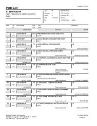
2.5.2 C5515 <strong>EVM</strong> Power Domain Probe Points<br />
The C5515 <strong>EVM</strong> has pre-designed probe points in the circuitry which could be used to<br />
observe power domains. Several of the power domains have INA219 power monitors<br />
and these domains have a 1 ohm resistor shunted on the <strong>EVM</strong>. The probe points with<br />
power monitors are shown in the table below.<br />
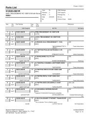
Table 27: C5515 <strong>EVM</strong> Power Probe Points With Power Monitors<br />
Jumper #/<br />
Schematic<br />
Page<br />
Signal<br />
# of Positions<br />
1 Ohm Shunt<br />
Resistor<br />
Installed at<br />
factory<br />
JP8 / 11 TPS65023_VCC_1V8 2 Monitor<br />
JP17 / 11 C5515 VDD_IO1 2 Monitor<br />
JP20 / 15 V1.8 2 Monitor<br />
JP22 / 13 VIN_<strong>EVM</strong> 2 Monitor<br />
JP23 / 15 VDD_IO2 2 Monitor - 0<br />
JP25 / 15 V3.3 2 Monitor<br />
JP37 / 11 VDDC 2 Monitor<br />
JP38 / 11 USB_VDD_IN 2 Monitor<br />
Shown below is a diagram of a typical Power Domain Probe Point with a one (1) ohm<br />
resistor.<br />
One (1) ohm<br />
resistor<br />
Figure 2-22, Diagram of a typical jumper<br />
2-29