TMS320C5515 Evaluation Module (EVM) - Spectrum Digital Support
TMS320C5515 Evaluation Module (EVM) - Spectrum Digital Support
TMS320C5515 Evaluation Module (EVM) - Spectrum Digital Support

Create successful ePaper yourself
Turn your PDF publications into a flip-book with our unique Google optimized e-Paper software.
<strong>Spectrum</strong> <strong>Digital</strong>, Inc<br />
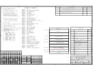
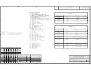
2.2.18 J19, Display Interface<br />
Connector J19 provides an interface to a display module. This connector is located on<br />
the bottom side of the board. The signals on this connector are shown in the table<br />
below.<br />
Table 11: J19, Display Interface<br />
Pin # Signal Name Pin # Signal Name<br />
1 GND 16 LCD_nWE / R/Wn<br />
2 V13 17 GND / BS0<br />
3 VCOMH 18 VDD_IO1 / BS1<br />
4 VDD_IO1 / VDDIO 19 LCD_BIAS_OE / CEn<br />
5 VSL 20 LCD_ALE / D/Cn<br />
6 NC 21 nRESET / RESETn<br />
7 LCD_DATA7 / D7 22 IREF<br />
8 LCD_DATA6 / D6 23 GPIO1<br />
9 LCD_DATA5 / D5 24 GPIO0<br />
10 LCD_DATA4 / D4 25 NC-25<br />
11 LCD_DATA3 / D3 26 VDD<br />
12 LCD_DATA2 / D2 27 VDD_IO1 / VCI<br />
13 LCD_DATA1 / D1 28 GND / VSS<br />
14 LCD_DATA0 / D0 29 NC-29<br />
15 LCD_RE / E/RDn 30 GND / NC-30<br />
2.2.19 M1, Left Microphone<br />
The M1 microphone (left channel) connects to the AIC_MIC1L input of the<br />
TLV320AIC3204.<br />
2.2.20 M2, Right Microphone<br />
The M2 microphone (right channel) connects to the AIC_MIC1R input of the<br />
TLV320AIC3204.<br />
2-16 <strong>TMS320C5515</strong> <strong>EVM</strong> Technical Reference