TMS320C5515 Evaluation Module (EVM) - Spectrum Digital Support
TMS320C5515 Evaluation Module (EVM) - Spectrum Digital Support
TMS320C5515 Evaluation Module (EVM) - Spectrum Digital Support

Create successful ePaper yourself
Turn your PDF publications into a flip-book with our unique Google optimized e-Paper software.
<strong>Spectrum</strong> <strong>Digital</strong>, Inc<br />
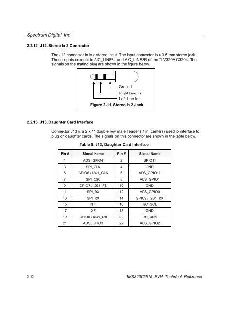
2.2.12 J12, Stereo In 2 Connector<br />
The J12 connector in is a stereo input. The input connector is a 3.5 mm stereo jack.<br />
These inputs connect to AIC_LINE3L and AIC_LINE3R of the TLV320AIC3204. The<br />
signals on the mating plug are shown in the figure below.<br />
Ground<br />
Right Line In<br />
Left Line In<br />
Figure 2-11, Stereo In 2 Jack<br />
2.2.13 J13, Daughter Card Interface<br />
Connector J13 is a 2 x 11 double row male header (.1 in. centers) used to interface to<br />
plug on daughter cards. The signals on this connector are shown in the table below.<br />
Table 8: J13, Daughter Card Interface<br />
Pin # Signal Name Pin # Signal Name<br />
1 ADS_GPIO4 2 GPIO11<br />
3 SPI_CLK 4 GND<br />
5 GPIO6 / I2S1_CLK 6 ADS_GPIO10<br />
7 SPI_CS0 8 ADS_GPIO1<br />
9 GPIO7 / I2S1_FS 10 GND<br />
11 SPI_DX 12 ADS_GPIO0<br />
13 SPI_RX 14 GPIO9 / I2S1_RX<br />
15 INT1 16 I2C_SCL<br />
17 XF 18 GND<br />
19 GPIO8 / I2S1_DX 20 I2C_SDA<br />
21 ADS_GPIO3 22 ADS_GPIO2<br />
2-12 <strong>TMS320C5515</strong> <strong>EVM</strong> Technical Reference