Software Manual - G4JNT
Software Manual - G4JNT
Software Manual - G4JNT
You also want an ePaper? Increase the reach of your titles
YUMPU automatically turns print PDFs into web optimized ePapers that Google loves.
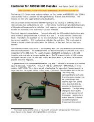
IF Offset<br />
A user defined IF offset which can be added to, or subtracted from, the input frequency can be<br />
stored in the PIC in EEProm. To change the stored value, hold down the pushbutton while<br />
switching on, or resetting the controller. Keep pressing the button until the introductory message<br />
goes and the display goes blank. On releasing the button, the IF offset setup display will appear;<br />
Press the button briefly to move through the digit<br />
to be changed, as indicated by the cursor. The<br />
rotary control is then used to set that digit. When<br />
under the sign, the rotary control is used to toggle<br />
between plus ‘+’ or minus ‘-‘ offset. TO<br />
complete the entry, press and hold the button for<br />
2 seconds, whereupon the new value will be stored to EEProm and normal operation resumes.<br />
Negative Frequencies<br />
The stored IF offset is added to, or subtracted from the input frequency. If a negative IF offset is<br />
stored that is significantly greater than the input frequency, the resulting display will correctly show<br />
a negative frequency. This capability has been included for upconverting receivers where the IF lies<br />
above the input band. In this situation , F IF = F RF + F LO , so the wanted indicated frequency (F RF ) is<br />
obtained by measuring F LO and subtracting the higher value of F IF to give a negative result.<br />
Frequency Meter <strong>Software</strong> details<br />
Refer to the source code listing FreqMeter.asm. As the TIMER1 counter is only 16 bits in length,<br />
it has to be continually tested for overflow by testing the flag in the interrupt enable register. Each<br />
time the counter overflows, another 16 bit counter made up of the two registers FreqCountHi/Lo are<br />
incremented, giving a 32 bit count overall.<br />
The main loop first calls the critical timing part of this software, the routine MeasureFreq Inside<br />
this routine, the combined 32 bit counter is first cleared and TIMER1 enabled to start it counting<br />
from the input signal. Another 16 bit counter GVHi/Lo is preloaded with a value defining the gate<br />
period. A loop is organised so is continually testing for overflow and decrementing a loop counter<br />
for each pass though with all branches and tests being carefully equalised to have constant length<br />
(number of clock cycles) by padding out with strategically placed nop statements. A constant delay<br />
of 16 clocks is achieved for each pass though. After the gate defining counter has decremented to<br />
zero after the required number of passes though the loop, TIMER1 is stopped and the resulting<br />
value frozen. The value to be prestored in Gv in therefore equal to the gate period in seconds,<br />
multiplied by the clock frequency of 1MHz and divided by the 16 clocks in the loop. 1s requires a<br />
value of 62500 (which just fits into a 16 bit count), 100ms gate period needs GV = 6250, and 10ms<br />
GV = 625<br />
The 32 bit count now holds the number of input cycles in either 10ms, 100ms or 1s gate time and<br />
needs to be corrected by the IF offset before display. The IF offset is stored in EEProm in units of<br />
<strong>G4JNT</strong> PIC Controller <strong>Software</strong> <strong>Manual</strong>. Page 6


