
Create successful ePaper yourself
Turn your PDF publications into a flip-book with our unique Google optimized e-Paper software.
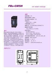
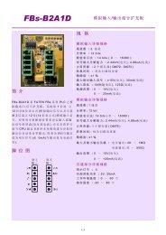
<st<strong>ro</strong>ng>FBs</st<strong>ro</strong>ng>-<st<strong>ro</strong>ng>2DA</st<strong>ro</strong>ng><br />
2 Channels Analog Output Module<br />
Int<strong>ro</strong>duction<br />
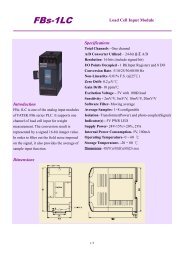
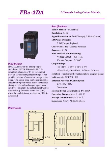
<st<strong>ro</strong>ng>FBs</st<strong>ro</strong>ng>-<st<strong>ro</strong>ng>2DA</st<strong>ro</strong>ng> is one of the analog output<br />
modules of FATEK <st<strong>ro</strong>ng>FBs</st<strong>ro</strong>ng> series PLC. It<br />
p<strong>ro</strong>vides 2 channels of 14 bit D/A output.<br />
Base on the different jumper settings it can<br />
p<strong>ro</strong>vide varieties of current or voltage output<br />
signal. The output code can be configured as<br />
unipolar or bipolar which makes the relation<br />
of output code and real output signal more<br />
intuitive. For safety, the output signal will be<br />
automatically forced to ze<strong>ro</strong>(0V or 0mA)<br />
when the module is not serviced by CPU for<br />
0.5 second<br />
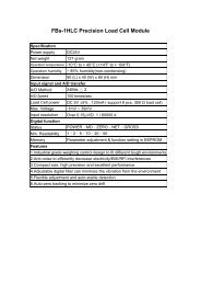
Specifications<br />
Total Channels –2 Channels<br />
Resolution- 14 bit<br />
Signal Resolution - 0.3mV(Voltage), 0.61uA(Current)<br />
I/O Points Occupied –<br />
2 RO(Output Register)<br />
Conversion Time- Updated each scan<br />
Accuracy- ±1 %<br />
Max. and Min. output loading-<br />
Voltage Output- 500~1MΩ<br />
Current Output- 0~500Ω<br />
Output Range-<br />
-10~+10V, -5~+5V, 0~10V, 0~5V<br />
-20~+20mA, -10~+10mA, 0~20mA, 0~10mA<br />
Isolation- Transformer(Power) and photo-coupler(Signal)<br />
Indicator(s) - 5V PWR LED<br />
External Power and Consumption-<br />
24V-15%/+20%,<br />
70mA max.<br />
Internal Power Consumption- 5V, 20mA<br />
Operating Temperature- 0 ~ 60 ℃<br />
Storage Temperature- -20 ~ 80 ℃<br />
Dimensions- 40(W)x90(H)x80(D) mm<br />
Dimensions<br />
1/4
<st<strong>ro</strong>ng>FBs</st<strong>ro</strong>ng>-<st<strong>ro</strong>ng>2DA</st<strong>ro</strong>ng><br />
2 Channels Analog Output Module<br />
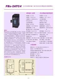
Wiring Diagram<br />
2/4
<st<strong>ro</strong>ng>FBs</st<strong>ro</strong>ng>-<st<strong>ro</strong>ng>2DA</st<strong>ro</strong>ng><br />
2 Channels Analog Output Module<br />
Jumper Setup<br />
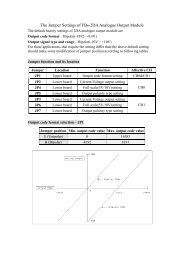
Output Code Format Selection<br />
There are two formats of output code can be selected, one is Unipolar and the other is Bipolar. The range<br />
of the Unipolar code value is 0~16383 while the Bipolar is –8192~8191. The extreme two ends of the<br />
code value corresponding to the minimal and maximal analog output level respectively. For example, if<br />
the analog signal is set to –10V~+10V range, for the same code value 0, the Bipolar code will result 0V<br />
output, while the Unipolar code will result –10V output, for the code value 8191, the Bipolar code will<br />
result 10V output, while the Unipolar code will result 0V output. The JP1 are shared for CH0, CH1 which<br />
means both channels can not configure to different output code format.<br />
Code Format Range JP1 Setting<br />
Bipolar -8192 ~ +8191<br />
Unipolar 0 ~ 16383<br />
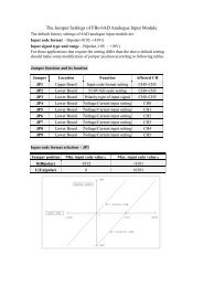
Output Signal Type Selection<br />
The output signal type of each channel can be set individually. There are three jumpers for each channel<br />
to cont<strong>ro</strong>l the output signal type. The corresponding jumpers for each channel are shown at below:<br />
JP3(CH1)<br />
JP2(CH0)<br />
JP4(CH0)<br />
JP5(CH0)<br />
JP1<br />
JP6(CH1)<br />
JP7(CH1)<br />
3/4
<st<strong>ro</strong>ng>FBs</st<strong>ro</strong>ng>-<st<strong>ro</strong>ng>2DA</st<strong>ro</strong>ng><br />
2 Channels Analog Output Module<br />
Please lookup the arrangement of jumper f<strong>ro</strong>m the following table according to the desired output signal<br />
type.<br />
Signal Type<br />
JP2/JP3<br />
JP4/JP6<br />
JP5/JP7<br />
0~20mA<br />
-20mA~+20mA<br />
0~10mA<br />
-10mA~+10mA<br />
0~10V<br />
-10V~+10V<br />
0~5V<br />
-5V~+5V<br />
The JP2,JP4,JP5 jumpers are used for CH0 output signal type setting while the JP3,JP6,JP7 jumpers are<br />
used for CH1.<br />
The default factory settings of <st<strong>ro</strong>ng>FBs</st<strong>ro</strong>ng>-<st<strong>ro</strong>ng>2DA</st<strong>ro</strong>ng> analogue output module are<br />
Output code format – Bipolar(-8192~+8191)<br />
Output signal type and range – Bipolar(-10V ~ +10V)<br />
For those applications that require the setting differ than the above default setting should make some<br />
modification according to the tables listed above<br />
4/4