Cam & groove couplings - LMC-Couplings
Cam & groove couplings - LMC-Couplings
Cam & groove couplings - LMC-Couplings

Create successful ePaper yourself
Turn your PDF publications into a flip-book with our unique Google optimized e-Paper software.
CAM & GROOVE COUPLINGS<br />
FED MIL / EN / DIN<br />
A.1<br />
STANDARD<br />
<br />
Federal Mil A-A-59326A<br />
The standard for cam & <strong>groove</strong> <strong>couplings</strong> is based on the US Military<br />
Specification Mil-C-27487. The Mil-C-27487 specified the casting methods,<br />
materials, dimensions, tolerances, pressure ratings and inspection procedures.<br />
In 1998, the original Mil-C-27487 specification was replaced by a new<br />
Federal Military standard: A-A-59326A. Federal Mil A-A-59326A guarantees<br />
interchangeability of <strong>couplings</strong> designed to the same specification.<br />
Interchangeability with other brands<br />
Between manufacturers cam & <strong>groove</strong> <strong>couplings</strong> are interchangeable with<br />
the exception of 1/2" (12.7 mm), 5" (127 mm) and 8" (203.2 mm).<br />
The A-A-59326A Mil-specification does not apply to 1/2", 5" and 8" cam & <strong>groove</strong><br />
<strong>couplings</strong>, due to the presence of two versions of cam & <strong>groove</strong> <strong>couplings</strong> in<br />
today’s market.<br />
Limitations: Hose shanks with larger serrations are not designed to be<br />
assembled with a ferrule or sleeve. Hose damage can result if they are<br />
swaged. The larger shank serrations will cut into the inner wall of the hose<br />
resulting in leakage or permanent hose failure.<br />
N.B.: <strong>Cam</strong> & <strong>groove</strong> <strong>couplings</strong> must never be used for steam or compressed air<br />
applications.<br />
CAM & GROOVE COUPLINGS FED MIL / EN / DIN<br />
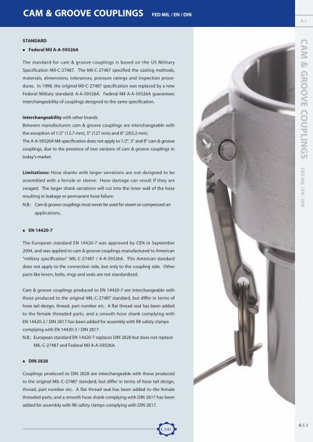
EN 14420-7<br />
The European standard EN 14420-7 was approved by CEN in September<br />
2004, and was applied to cam & <strong>groove</strong> <strong>couplings</strong> manufactured to American<br />
“military specification” MIL-C-27487 / A-A-59326A. This American standard<br />
does not apply to the connection side, but only to the coupling side. Other<br />
parts like levers, bolts, rings and seals are not standardized.<br />
<strong>Cam</strong> & <strong>groove</strong> <strong>couplings</strong> produced to EN 14420-7 are interchangeable with<br />
those produced to the original MIL-C-27487 standard, but differ in terms of<br />
hose tail design, thread, part number etc. A flat thread seal has been added<br />
to the female threaded parts, and a smooth hose shank complying with<br />
EN 14420-2 / DIN 2817 has been added for assembly with RK safety clamps<br />
complying with EN 14420-3 / DIN 2817.<br />
N.B.: European standard EN 14420-7 replaces DIN 2828 but does not replace<br />
MIL-C-27487 and Federal Mil A-A-59326A.<br />
DIN 2828<br />
<strong>Couplings</strong> produced to DIN 2828 are interchangeable with those produced<br />
to the original MIL-C-27487 standard, but differ in terms of hose tail design,<br />
thread, part number etc. A flat thread seal has been added to the female<br />
threaded parts, and a smooth hose shank complying with DIN 2817 has been<br />
added for assembly with RK safety clamps complying with DIN 2817.<br />
A.1.1
CAM & GROOVE COUPLINGS<br />
FED MIL / EN / DIN<br />
PRODUCT RANGE<br />
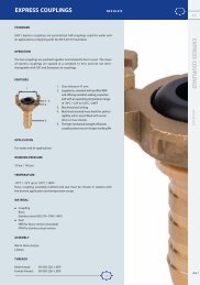
OPERATION<br />
To connect<br />
1. Open the coupler by pulling back the locking lever above the cam handles, whilst rotating the handles<br />
away from the body of the coupler.<br />
2. Insert the adaptor into the coupler<br />
3. Close the coupler by rotating the cam handles towards the body of the coupler. Locking occurs when<br />
the cam handles are closed. The coupler is properly closed when the locking levers on both the cam<br />
handles assemblies are flush. For extra security, insert safety clip through the holes above the cam<br />
handles. Line pressure, which moves the coupler and adaptor independently, increases the pressure<br />
on the cam face, ensuring increased locking leverage. Under normal conditions, safety locks are not<br />
necessary, but are recommended. The adaptor and the coupler are designed to minimize the fluid<br />
turbulence and the abrasion from dry products when connected.<br />
To disconnect<br />
4. Be sure that the hose-coupling connection is depressurized before disconnecting.<br />
5. Open the coupler by pulling back the locking lever above the cam handles, whilst rotating the handles<br />
away from the body of the coupler.<br />
6. Remove the adaptor from the coupler.<br />
7. Close the coupler by rotating the cam handles towards the body of the coupler. Locking the coupler<br />
when not in use will help protect it from accidental damage.<br />
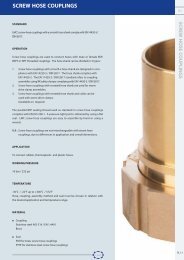
FEATURES<br />
2<br />
4<br />
5<br />
3 10 11 12<br />
6<br />
7<br />
1<br />
9<br />
8<br />
1<br />
1<br />
1<br />
1. Stainless steel triangular handles, pin, ring and safety pin are standard on all<br />
material versions. Handles manufactured by investment casting.<br />
2. Holes for safety pin inserts<br />
3. Earthing lug<br />
4. Reinforced coupling section for increased mechanical strength<br />
5. Long hose shank to ensure secure fixing<br />
6. Marked with cam & <strong>groove</strong> type<br />
7. Marked with diameter<br />
8. Marked with standard compliance: MS (Military Specification) or DIN (Deutsche<br />
Industrienorm)<br />
9. Marked with material identification: stainless steel, brass, bronze, aluminium,<br />
polypropylene<br />
10. Seals are available in NBR (standard), EPDM (for polypropylene), PTFE, CSM,<br />
FPM, FEP/Silicone, PTFE/EPDM and PTFE/FPM<br />
11. Safety couplers are available with monoblock safety boddy<br />
12. Coupling insurance by brand name <strong>LMC</strong>-<strong>Couplings</strong> ®<br />
APPLICATION<br />
<strong>Cam</strong> & <strong>groove</strong> <strong>couplings</strong> are used for hose-to-hose or hose-to-pipe / manifold connections for the transfer of liquids or dry bulk products.<br />
A.1.2<br />
Chapter A: Quick <strong>couplings</strong>
CAM & GROOVE COUPLINGS<br />
FED MIL / EN / DIN<br />
PRODUCT RANGE<br />
A.1<br />
WORKING PRESSURE<br />
INCH 1/2" 3/4"-2" 2.1/2" 3" 4" 5" 6" 8"<br />
Working pressure Bar Psi Bar Psi Bar Psi Bar Psi Bar Psi Bar Psi Bar Psi Bar Psi<br />
Brass 11 150 18 250 11 150 9 125 7 100 5 75 5 75 - -<br />
Bronze - - 18 250 11 150 9 125 7 100 - - - - - -<br />
Aluminium 11 150 18 250 11 150 9 125 7 100 5 75 5 75 5 75<br />
Stainless steel 11 150 18 250 16 225 14 200 7 100 7 100 7 100 3 50<br />
TEMPERATURE RANGE<br />
The working pressures shown above refer to ambient temperatures using elastomer seals. Higher temperatures and / or PTFE seals will<br />
reduce the rated coupling pressure. In the case of polypropylene, the maximum working temperature is 70°C / 160°F, at which<br />
temperature the working pressures shown above should be reduced by 40%.<br />
Hose, coupling, seal and assembly method must be chosen in relation with the desired application and temperature range.<br />
MATERIAL<br />
<br />
Coupling<br />
<strong>LMC</strong>-<strong>Couplings</strong> cam & <strong>groove</strong> <strong>couplings</strong> are available in the following materials:<br />
CAM & GROOVE COUPLINGS FED MIL / EN / DIN<br />
Stainless steel: AISI 316 - EN 1.4401<br />
Brass: C85700<br />
Bronze: C84400<br />
Aluminium: 380<br />
Polypropylene: <strong>LMC</strong>’s polypropylene cam & <strong>groove</strong> <strong>couplings</strong> contain 25-30% fiberglass reinforcements<br />
Production method<br />
All sizes of brass and bronze cam & <strong>groove</strong> <strong>couplings</strong> are shell-moulded or sand cast.<br />
The type of aluminium is a sand cast 713-T5 alloy, which can be anodised if required.<br />
Stainless steel <strong>couplings</strong> are investment-cast in a range of common sizes and are electro-polished for clean applications.<br />
The stainless steel quality for cam & <strong>groove</strong> <strong>couplings</strong> is standard AISI 316-EN 1.4401.<br />
Polypropylene <strong>couplings</strong> are made from polypropylene reinforced with 25%-30% acid-resistant fibreglass.<br />
Chapter A: Quick <strong>couplings</strong><br />
A.1.3
CAM & GROOVE COUPLINGS<br />
FED MIL / EN / DIN<br />
W W W. L M C- C O U P L I N G S. C O M<br />
Materials and sizes<br />
INCH 1/2” 3/4”-2” 2.1/2” 3”-4” 5”-6” 8”<br />
Materials and sizes<br />
ND 13 20-50 65 75-100 125-150 200<br />
Brass -<br />
Bronze - -<br />
Aluminium <br />
Stainless steel <br />
Polypropylene - - -<br />
Available<br />
- Not available<br />
Material<br />
Seal<br />
Standard seal<br />
The standard cam & <strong>groove</strong> seal consists of a standard square-section, available in:<br />
NBR - Silicone free (standard for all materials, except polypropylene)<br />
EPDM (standard for material polypropylene)<br />
FPM<br />
CSM<br />
Closed seal<br />
VLXPSG closed cam & <strong>groove</strong> seals are designed for extreme chemical applications. These seals combine the best properties of two<br />
different materials; the pressure set of the rubber silicone core and the chemical resistance provided by the FEP encapsulation.<br />
Encapsulation of the Silicone core ensures improved operational safety, when compared with an open envelope seal.<br />
VLXPSG seals are produced without the use of animal derived ingredients, ADI free. This reduces the risk of BSE prion contamination.<br />
VLXPSG closed cam & <strong>groove</strong> seals resist high temperature operation: from -60°C / -76°F up to 204°C / 399°F.<br />
FEP envelope<br />
Silicone core (standard)<br />
FPM core (on request)<br />
Open envelope seal<br />
The open envelope seal consists of a U-section PTFE envelope and a square-section EPDM core. The construction method used for the<br />
open envelope seal ensures excellent compression properties. The PTFE envelope allows the seal to withstand temperatures up to<br />
200°C / 382°F.<br />
PTFE envelope<br />
EPDM core (standard)<br />
FPM and silicone core (on request)<br />
A.1.4<br />
Chapter A: Quick <strong>couplings</strong>
CAM & GROOVE COUPLINGS<br />
FED MIL / EN / DIN<br />
W W W. L M C- C O U P L I N G S. C O M<br />
A.1<br />
Closed envelope seal<br />
The closed envelope seal removes all contact between chemicals and the seal core. The fully-closed PTFE envelope<br />
completely encapsulates the FPM. The maximum temperature for this type is 200°C / 392°F.<br />
PTFE envelope<br />
FPM core (standard)<br />
VMQ core (on request)<br />
Thread seal<br />
Female threaded coupler and adaptor components complying with EN 14420-7 / DIN 2828 standards contain a thread<br />
seal. Female threaded cam & <strong>groove</strong> <strong>couplings</strong> are sealed by screwing a male BSPT / BSP thread up to the thread seal.<br />
Thread seals are available in: PTFE - PUR<br />
Properties seals<br />
PTFE or PUR<br />
REF. ASTM POLYMER TRADE NAME HARDNESS °C °F + PROPERTIES -<br />
VLXB... NBR Acrylonitrile Butadiene Perbunan ® 60 +/- 5 -30°C -22°F Oil based hydraulic Ozone,<br />
Shore A 120°C 248°F fluid, fats, animal and sunlight<br />
vegetable oils, flame<br />
weather<br />
retardant, liquids, grease,<br />
water and air<br />
CAM & GROOVE COUPLINGS FED MIL / EN / DIN<br />
VLXE... EPDM Ethylene-propylene- Keltan ® 70 +/- 5 -40°C -40°F Acids, steam, alcohol Oil,<br />
Diene Rubber Shore A 145°C 293°F greases<br />
VLXV... FPM Fluorocarbon Viton ® 70 +/- 5 -30°C -22°F Mineral oils and greases, Steam<br />
Shore A 200°C 392°F alifatic, aromatic, and also<br />
special chlorinated hydrocarbons,<br />
petrol, diesel fuels,<br />
silicon oils and greases<br />
VLXH... CSM Chlorosylfonated Hypalon ® 70 +/- 5 -40°C -40°F Acids and oils, obsolescent Chlorine<br />
polyethylene Shore A 140°C 284°F and ozone resistant<br />
VLXPSG... FEP / Copolymer of Hexa-fluorpropylene / Teflon ® / 60 +/- 5 -60°C -76°F Resistant to almost all kinds Hardness<br />
VMQ Silicone Silicone Shore D 204°C 399°F of chemical products, steam,<br />
oils... Excellent self-lubricating<br />
and anti adhesive properties<br />
VLXP... PTFE / Poly tetrafluorethylene / Teflon ® / 85 +/-5 -25°C -13°F Alcohols, acids Hardness<br />
EPDM Keltan ® Shore D 100°C 212°F Oil, greases<br />
VLXP...V PTFE / Poly tetrafluorethylene / Teflon ® / 85 +/-5 -10°C 14°F Mineral oils and greases, Low temp.<br />
FPM Fluorocarbon Viton ® Shore D 200°C 392°F alifatics, aromatics<br />
VLXPG... PTFE / Poly tetrafluorethylene / TFM TM / 74 +/- 5 -15°C -5°F Acids and oils, obsolescent Benzene,<br />
FPM Fluorocarbon Viton ® Shore D 200°C 392°F and ozone resistant toluene,<br />
petrol<br />
NBR= Perbunan ® is a registered trademark of Bayer AG / EPDM= Keltan ® is a registered trademark of DSM / FPM= Viton ® is a registered trademark of DuPont Performance Elastomer<br />
CSM= Hypalon ® is a registered trademark of DuPont Performance Elastomer / PTFE = Teflon ® is a registered trademark of DuPont Performance Elastomer<br />
VMQ = Silplus ® is a registered trademark of General Electric Co / TFM TM is a registered trademark of Dyneon.<br />
Chapter A: Quick <strong>couplings</strong><br />
A.1.5
CAM & GROOVE COUPLINGS<br />
FED MIL / EN / DIN<br />
W W W. L M C- C O U P L I N G S. C O M<br />
ASSEMBLY<br />
Worm drive clamps<br />
RK safety clamps to EN-14420-3 / DIN 2817<br />
RKP safety clamps to EN-14420-3 / DIN 2817<br />
FLEXOLINE ® safety clamps<br />
Welding: butt welding and socket welding (see pg. A.1.27)<br />
THREADS<br />
Three different types of thread are generally used for cam & <strong>groove</strong> <strong>couplings</strong>:<br />
BSP = British Standard Pipe<br />
BSPT = British Standard Pipe Taper<br />
NPT = National Pipe Taper<br />
In Europe, BSP and BSPT threads are more commonly used than NPT threads. NPT threads are typically American threads. Since many<br />
American industrial machines and products are exported to European markets, <strong>couplings</strong> with NPT threads are a regular requirement. The<br />
main difference between the three thread types referred to above is the seal method used. Although BSP threads are sealed using a seal<br />
or o-ring, BSPT and NPT threads are sealed by their conical thread.<br />
THREAD DESCRIPTION STANDARD TYPICAL CALL OUT SEALING METHOD PROPERTIES<br />
BSP British standard pipe EN ISO 228-1 G1 Parallel thread 55° degree thread angle<br />
DIN ISO 228-1 Pressure tight joint is Trucation of rood and crest<br />
obtained with a seal<br />
are round<br />
or o-ring Diameter measured in inches<br />
BSPT British standard EN 10226-1 R1 Conical thread. 55° degree thread angle<br />
pipe taper DIN 2999-1 Pressure tight joint is Trucation of rood and crest<br />
achieved by the thread are round<br />
BSPP British standard G 1(cyl) Cylindrical thread 55° degree thread angle<br />
pipe parallel<br />
Trucation of rood and crest<br />
are round<br />
NPT National pipe taper ANSI B 1.20.1 NPT 1 Conical thread 60° degree round angle<br />
(American standard pipe thread) Pressure tight joint is Trucation of rood and crest<br />
achieved by the thread are flat<br />
<strong>Cam</strong> & <strong>groove</strong> threads<br />
COUPLING TYPE STANDARD ON REQUEST<br />
ADAPTOR<br />
Female threaded A BSP EN ISO 228-1/ DIN ISO 228-1 NPT ANSI B 1.20.1<br />
Male threaded F BSPT EN 10226-1 / DIN 2999-1 NPT ANSI B 1.20.1<br />
COUPLER<br />
Female threaded D BSP EN ISO 228-1/ DIN ISO 228-1 NPT ANSI B 1.20.1<br />
Male threaded B BSPT EN 10226-1 / DIN 2999-1 NPT ANSI B 1.20.1<br />
A.1.6<br />
Chapter A: Quick <strong>couplings</strong>
CAM & GROOVE COUPLINGS<br />
FED MIL / EN / DIN<br />
W W W. L M C- C O U P L I N G S. C O M<br />
A.1<br />
TESTING<br />
The following aspects of <strong>LMC</strong>’s cam & <strong>groove</strong> <strong>couplings</strong> are tested in house:<br />
<br />
<br />
<br />
<br />
<br />
<br />
<br />
Adaptor and coupler dimensions<br />
Material quality<br />
Handle strength<br />
Seal properties<br />
Thread dimensions<br />
Impact resistant<br />
Adaptor and coupler dimensions<br />
High-technology measuring equipment<br />
High-technology measuring tools are used to measure the specific dimensions of cam &<br />
<strong>groove</strong> <strong>couplings</strong> to ensure compliance with the dimensions required under the Federal Mil<br />
A-A-59326A, European EN 14420-7 and the German DIN 2828 standards. Although ordinary<br />
measuring systems are unable to give sufficiently precise dimensions for this purpose, our<br />
high-technology measuring system is able to measure complex cam & <strong>groove</strong> coupling product<br />
positions and shapes.<br />
Dimension gauges<br />
The shape of the adaptor coupling enables the interchangeability of coupler parts. Specially<br />
designed gauges are used in addition to measurement systems. The use of test gauges<br />
minimises inspection times, ensures interchangeability and maintains seal properties when<br />
using specially-designed seals, such as envelope seals.<br />
Two gauges are used for each dimension; one small and the other larger. In the first stage of<br />
testing, the small gauge is passed across the head of the adaptor section. If the gauge can not<br />
pass, the adapter head falls within the permissible – (minus) tolerances.<br />
If the larger gauge passes across the adaptor head with no interruption, the component is<br />
compliant and its dimensions fall within the permissible + (plus) tolerances.<br />
CAM & GROOVE COUPLINGS FED MIL / EN / DIN<br />
<br />
Material quality<br />
An in-house spectroscope is used to identify the materials used in the cam & <strong>groove</strong> <strong>couplings</strong>.<br />
The spectroscope analyses the precise quantity of all materials of the coupling.<br />
We can therefore offer our customers a guarantee that the materials used comply fully with the<br />
relevant standard.<br />
Chapter A: Quick <strong>couplings</strong><br />
A.1.7
CAM & GROOVE COUPLINGS<br />
FED MIL / EN / DIN<br />
W W W. L M C- C O U P L I N G S. C O M<br />
<br />
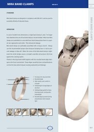
Handle strength<br />
<strong>LMC</strong> handles are designed to resist a wide range of applications in many industries. All standard handles are investment-cast and<br />
triangular in section. The production method and triangular section guarantees excellent mechanical properties. The wear resistance<br />
of this material was tested using a Rockwell hardness tester. <strong>LMC</strong> handles achieve better test results than sintered handles.<br />
Sintered handles begin to fracture when subjected to a load of 1600 Kg, <strong>LMC</strong> handles do not even start to bend until subjected to a<br />
load of 1000 Kg. Even when subjected to a load of 2400 Kg, <strong>LMC</strong> cam & <strong>groove</strong> handles still show no sign of fracture.<br />
6000<br />
5000<br />
(*) Fractured.<br />
(0, ) Bend, not fracture.<br />
4000<br />
Load (kg)<br />
3000<br />
2000<br />
1000<br />
0<br />
P/M<br />
* <strong>LMC</strong><br />
0 0<br />
X<br />
0.0 2.5 5.0 7.5 10.0 12.5 15.0<br />
Bending stroke (mm)<br />
Bend investment cast <strong>LMC</strong> handle<br />
Fractured sintered handle<br />
<br />
Seal properties<br />
After chemical structure, seal compression set has the next most significant effect on the seal of cam & <strong>groove</strong> <strong>couplings</strong>. A seal of<br />
correct hardness will ensure that the cam & <strong>groove</strong> coupling is sealed properly and safely. <strong>Cam</strong> & <strong>groove</strong> seal hardness is tested using<br />
a durometer.<br />
<br />
Thread dimensions<br />
All cam & <strong>groove</strong> threads are tested using thread gauges. Our production site has gauges for all dimensions and all standards.<br />
<br />
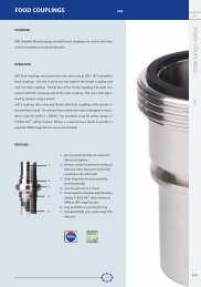
Impact resistance<br />
Impact resistance tests were carried out on 3” and 4” aluminium couplers and nine other brands in order to test the mechanical<br />
strength of <strong>LMC</strong> cam & <strong>groove</strong> <strong>couplings</strong>. A 2.3 kg / 5 lbs weight was dropped from a height of 1.5 metres / 5 feet, and the impact on<br />
the coupler body measured.<br />
A<br />
Impact<br />
B<br />
Drop weight impact on<br />
bowl of coupler<br />
Original ID: A<br />
ID after impact: B<br />
BRAND<br />
E<br />
F<br />
G<br />
H<br />
I<br />
J<br />
K<br />
<strong>LMC</strong><br />
M<br />
PRODUCTION METHOD<br />
Gravity cast<br />
Gravity cast<br />
Sand cast<br />
High pressure die cast<br />
High pressure die cast<br />
Squeeze die cast<br />
High pressure die cast<br />
High pressure die cast<br />
High pressure die cast<br />
A.1.8<br />
Chapter A: Quick <strong>couplings</strong>
CAM & GROOVE COUPLINGS<br />
FED MIL / EN / DIN<br />
W W W. L M C- C O U P L I N G S. C O M<br />
A.1<br />
Size 3”<br />
Type C C C C C C C B B C C D C<br />
Brand E F G H H I J K K K K K <strong>LMC</strong><br />
Original ID A 92.14 91.72 91.98 92.21 92.01 92.53 91.98 92.24 92.42 92.74 92.58 92.15 93.54<br />
1 91.75 89.43 89.86 91.06 91.67 90.98 91.16 91.43 91.12 91.48 91.59 91.31 93.17<br />
2 91.38 88.65 90.57 90.54 90.08 89.57 91.00 90.43 90.68 91.20 90.75 92.57<br />
3 90.73 90.54 90.27 89.06 88.66 90.26 90.30 90.28 91.11 90.38 92.57<br />
4 90.56 90.25 90.09 90.12 89.28 90.68 90.30 92.35<br />
5 90.16 90.05 89.83 90.65 89.78 92.19<br />
6 90.11 90.00 90.47 89.72 91.92<br />
7 89.55 89.49 91.89<br />
8 89.35 89.44 91.87<br />
9 89.37 89.33 91.79<br />
10 89.33 91.77<br />
11 89.22 91.76<br />
12 89.14 91.55<br />
13 91.68<br />
14 91.58<br />
15 91.58<br />
16 91.65<br />
17 91.61<br />
18 91.19<br />
19 91.15<br />
20 91.18<br />
21 91.08<br />
22 90.58<br />
23 90.05<br />
Impact times B<br />
Measurements in mm<br />
Adaptor unable to fit in coupler<br />
Coupler cracked<br />
CAM & GROOVE COUPLINGS FED MIL / EN / DIN<br />
Test result<br />
The impact resistance test showed that the product quality of cam & <strong>groove</strong> <strong>couplings</strong> is variable. Nine couplers from different<br />
manufacturers were also tested.<br />
Four brands of adaptor were unable to fit the corresponding coupler following a single impact from a 2.3 kg / 5 lbs weight dropped<br />
from a height of 1.5 metres / 5 feet. However, it took 18 such impacts before <strong>LMC</strong>-<strong>Couplings</strong> couplers were unable to fit their adaptors.<br />
The average number of impacts required before fractures became aparent was 4.25. <strong>LMC</strong>-<strong>Couplings</strong> couplers resisted 23 impacts before<br />
showing signs of fracture; a result far in excess of the average value.<br />
94.50<br />
FUNCTIONAL<br />
0 *<br />
0 *<br />
DX (MM)<br />
92.50<br />
90.50<br />
0 *<br />
2 *<br />
3 *<br />
0 *<br />
0 *<br />
0 *<br />
1 *<br />
0 *<br />
1 *<br />
2 *<br />
0 *<br />
1 *<br />
0 *<br />
0<br />
0 *<br />
*<br />
1 *<br />
1<br />
1*<br />
*<br />
2 *<br />
2 *<br />
0 *<br />
1 *<br />
2 *<br />
0 *<br />
1 *<br />
2 *<br />
0 *<br />
1 *<br />
2 *<br />
17 *<br />
18 * 18 *<br />
19 *<br />
1 *<br />
88.50<br />
1 *<br />
DISABLED<br />
C(E) C(F) C(G) C(H) C(H) C(I) C(J) B(K) B(K) C(K) C(K) D(K) C(<strong>LMC</strong>) C(<strong>LMC</strong>)<br />
Chapter A: Quick <strong>couplings</strong><br />
A.1.9
CAM & GROOVE COUPLINGS<br />
FED MIL / EN / DIN<br />
W W W. L M C- C O U P L I N G S. C O M<br />
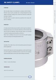
COATINGS<br />
Sometimes standard cam & <strong>groove</strong> coupling materials, like stainless steel, are not sufficiently resistant to extremely aggressive chemicals.<br />
However, at <strong>LMC</strong>-<strong>Couplings</strong>, our <strong>couplings</strong> feature high-resistance coatings, such as:<br />
<br />
<br />
<br />
ECTFE<br />
PTFE<br />
PFA<br />
ECTFE (up to 1000µ)<br />
ECTFE (Ethylene chlorotrifluoroethylene) coatings are designed to resist highly-concentrated and aggressive chemicals. <strong>Couplings</strong><br />
with an ECTFE-coating show excellent electric isolating and fire properties and resist to temperatures up to 150°C / 302°F.<br />
PFA (up to 200µ)<br />
The key quality of a PFA (Perfluoroalkoxy) coating is the temperature resistance up to 260°C / 500°F. Their effective anti-ad-hesive<br />
layer makes PFA coatings particularly well-suited to food and pharmaceutical industry applications.<br />
PTFE (up to 40µ)<br />
PTFE (Poly tetrafluoroethylene) coatings are only 40µ thick. PTFE-coated <strong>couplings</strong> can withstand temperatures up to 260°C / 500°F.<br />
Like PFA-coated <strong>couplings</strong>, PTFE <strong>couplings</strong> have excellent anti-adhesive qualities and are suitable for food industry applications.<br />
PVDF (up to 800µ)<br />
Like ECTFE coatings, PVDF (Polyvinylidene fluoride) coatings can resist highly-concentrated and aggressive chemicals, but with the<br />
added advantage of high temperature resistance. These <strong>couplings</strong> are wear-proof and also suitable for food industry applications.<br />
PTFE liner<br />
<strong>LMC</strong>-<strong>Couplings</strong> is able to provide his customers PTFE lined <strong>couplings</strong>. Our PTFE<br />
facility has been specially built to meet the highest industrial requirements.<br />
This room is separated from our other production facilities to ensure a clean<br />
and dust-free working environment. PTFE lined <strong>couplings</strong> are used in the pharmaceutical,<br />
cosmetics and food industry for applications with a temperature<br />
range of maximum 40°C / 104°F. Please contact our sales department for<br />
further information.<br />
A.1.10<br />
Chapter A: Quick <strong>couplings</strong>
CAM & GROOVE COUPLINGS<br />
FED MIL / EN / DIN<br />
W W W. L M C- C O U P L I N G S. C O M<br />
A.1<br />
ACCESSORIES<br />
All <strong>LMC</strong>-<strong>Couplings</strong>, cam & <strong>groove</strong> <strong>couplings</strong> (stainless steel, brass, bronze, aluminium and<br />
polypropylene)* as standard are supplied with stainless steel investment-cast triangular-section<br />
handles. Stainless steel provides the best chemical resistance. Their triangular section and<br />
investment-casting production method improves the mechanical strength of the handle.<br />
Even greater security and safety is ensured by <strong>LMC</strong>’s cam & <strong>groove</strong> <strong>couplings</strong> with patented<br />
safety handles. Simply push the nut on the handle downwards and the coupling connection is<br />
sealed. The safety version of <strong>LMC</strong>’s cam & <strong>groove</strong> <strong>couplings</strong> can be made extra-secure by<br />
using the safety pin, as on all standard <strong>LMC</strong>-<strong>Couplings</strong> cam & <strong>groove</strong> <strong>couplings</strong>.<br />
Where dust caps (type DC) are used to terminate hose or pipe assemblies, <strong>LMC</strong>’s lockable handles<br />
offer even higher safety levels. These patented L-shaped handles are physically locked, so<br />
that the dust cap can only be removed by unlocking the handles with a key. Safety handles are<br />
also recommended to secure dust caps.<br />
* With exception of 8"<br />
1<br />
2<br />
3<br />
CAM & GROOVE COUPLINGS FED MIL / EN / DIN<br />
1 2 3<br />
Handle types<br />
TYPE HANDLE MATERIAL REFERENCE 1/2" 3/4" 1" 1.1/4" 1.1/2" 2" 2.1/2" 3" 4" 5" 6" 8"<br />
Investment-cast Stainless steel VLHRPR <br />
triangular handle standard<br />
Investment-cast Brass VLHRPM - - - - - -<br />
triangular handle<br />
Safety locking handle Stainless steel VLHRPR S - - - - - - - -<br />
Cap L-handle Stainless steel VLHRPR L - - - -<br />
available<br />
- not available<br />
8" aluminium with 4 handles<br />
4" polypropylene with 3 handles<br />
1/2” with 1 handle for all materials<br />
Chapter A: Quick <strong>couplings</strong><br />
A.1.11
CAM & GROOVE COUPLINGS<br />
FED MIL / EN / DIN<br />
W W W. L M C- C O U P L I N G S. C O M<br />
CROSS REFERENCES<br />
<strong>Cam</strong> & <strong>groove</strong> <strong>couplings</strong><br />
COUPLING TYPE DESCRIPTION EN REFERENCE COMMON USED REF.<br />
A Adapter, female threaded Federal Mil - 633-ABS<br />
AF Adapter, female threaded EN 14420-7 / DIN 2828 AF 633-ABSF<br />
with thread seal<br />
B Coupler, female threaded EN 14420-7 / Federal Mil BF 633-BB<br />
C Coupler, with serrated hose shank Federal Mil - 633-C<br />
CC Coupler, with hose shank EN 14420-7 / DIN 2828 CC 633-CC<br />
D Coupler, female threaded Federal Mil - 633-DBS<br />
DF Coupler, female threaded EN 14420-7 / DIN 2828 DF 633-DBSF<br />
with thread seal<br />
E Adapter, with serrated hose shank Federal Mil - 633-E<br />
EC Adapter, with smooth hose shank EN 14420-7 / DIN 2828 EC 633-EC<br />
F Adapter, male threaded Federal Mil / EN 14420-7 FF 633-FB<br />
K Female dust cap Federal Mil / EN 14420-7 DC 634-B<br />
P Male dust plug Federal Mil / EN 14420-7 DP 634-A<br />
<strong>Cam</strong> & <strong>groove</strong> coupling<br />
Material<br />
A: Aluminium<br />
B: Bronze<br />
M: Brass<br />
P: Polypropylene<br />
R: Stainless steel<br />
VL A * 13 *<br />
Size<br />
-: Federal Mil A-A-59326A<br />
D: EN 14420-7 / DIN 2828<br />
S: With safety handles<br />
SD: EN 14420-7 / DIN 2828 with safety handles<br />
N: NPT thread<br />
<strong>Cam</strong> & <strong>groove</strong> seals<br />
<strong>Cam</strong> & <strong>groove</strong> coupling<br />
VL X * 13<br />
Size<br />
Seal<br />
Material<br />
B: NBR square seal<br />
E: EPDM square seal<br />
V: FPM square seal<br />
H: CSM square seal<br />
P: PTFE / EPDM open envelope seal<br />
PG: PTFE / FPM closed envelope seal<br />
PSG: FEP / Silicone closed square seal<br />
A.1.12<br />
Chapter A: Quick <strong>couplings</strong>
CAM & GROOVE COUPLINGS<br />
FED MIL / EN / DIN<br />
W W W. L M C- C O U P L I N G S. C O M<br />
A.1<br />
DIMENSIONS<br />
ND Inch A B C D E F G H J K L<br />
13 1/2" 30 40 31 46 13 31 66 10 46 14 33<br />
20 3/4" 115 50 33 49 19 55 85 14 49 21 34<br />
25 1" 138 62 40 60 24 40 98 20 60 26 41<br />
32 1.1/4” 178 81 46 68 31 46 104 26 70 35 48<br />
40 1.1/2” 185 87 48 70 38 48 109 32 73 38 50<br />
50 2" 195 90 54 79 48 54 124 43 79 46 57<br />
65 2.1/2” 208 111 55 85 62 55 135 54 87 56 59<br />
80 3" 250 143 57 90 75 57 159 66 92 73 62<br />
100 4" 270 171 61 101 100 61 169 89 101 98 65<br />
125 5" 300 - 61 101 122 61 188 118 105 128 65<br />
150 6" 400 254 67 112 150 67 240 140 111 144 73<br />
CAM & GROOVE COUPLINGS FED MIL / EN / DIN<br />
M N O P S T U V W X Y Z AA<br />
13 24 37 14 10 62 28 24 52 37 14 4 26<br />
13 32 40 19 14 76 25 32 57 40 19 10 26<br />
13 43 48 23 19 92 36 43 69 49 23 10 23<br />
13 50 55 28 25 98 41 58 77 55 28 10 40<br />
13 56 36 36 31 102 44 56 78 56 36 10 42<br />
13 68 62 46 43 117 49 68 87 62 46 10 48<br />
13 85 86 56 56 129 51 85 98 68 56 10 49<br />
13 102 88 73 64 153 51 102 108 70 73 10 51<br />
13 126 78 98 89 168 55 126 118 78 98 12 53<br />
13 - 83 118 118 188 56 - 103 63 118 12 58<br />
16 - 82 150 138 230 60 - 108 68 150 12 58<br />
Dimensions in mm and are given as illustration only.<br />
Chapter A: Quick <strong>couplings</strong><br />
A.1.13
CAM & GROOVE COUPLINGS<br />
W W W. L M C- C O U P L I N G S. C O M<br />
A.1<br />
TYPE A: ADAPTOR FEMALE THREADED<br />
ND Inch Thread Material Weight/pc Reference<br />
EN ISO 228-1<br />
Kg<br />
15 1/2” G 1/2 Aluminium 0.02 VLAA013<br />
20 3/4” G 3/4 Aluminium 0.04 VLAA019<br />
25 1” G 1 Aluminium 0.05 VLAA025<br />
32 1.1/4” G 1.1/4 Aluminium 0.09 VLAA032<br />
40 1.1/2” G 1.1/2 Aluminium 0.11 VLAA038<br />
50 2” G 2 Aluminium 0.15 VLAA050<br />
65 2.1/2” G 2.1/2 Aluminium 0.24 VLAA063<br />
80 3” G 3 Aluminium 0.27 VLAA075<br />
100 4” G 4 Aluminium 0.58 VLAA100<br />
125 5” G 5 Aluminium 0.90 VLAA125<br />
150 6” G 6 Aluminium 0.84 VLAA150<br />
200 8” G 8 Aluminium 2.31 VLAA200<br />
15 1/2” G 1/2 Stainless steel 0.07 VLAR013<br />
20 3/4” G 3/4 Stainless steel 0.11 VLAR019<br />
25 1” G 1 Stainless steel 0.15 VLAR025<br />
32 1.1/4” G 1.1/4 Stainless steel 0.24 VLAR032<br />
40 1.1/2” G 1.1/2 Stainless steel 0.32 VLAR038<br />
50 2” G 2 Stainless steel 0.42 VLAR050<br />
65 2.1/2” G 2.1/2 Stainless steel 0.71 VLAR063<br />
80 3” G 3 Stainless steel 0.73 VLAR075<br />
100 4” G 4 Stainless steel 1.42 VLAR100<br />
125 5” G 5 Stainless steel 1.92 VLAR125<br />
150 6” G 6 Stainless steel 3.17 VLAR150<br />
15 1/2” G 1/2 Brass 0.07 VLAM013<br />
20 3/4” G 3/4 Brass 0.10 VLAM019<br />
25 1” G 1 Brass 0.15 VLAM025<br />
32 1.1/4” G 1.1/4 Brass 0.20 VLAM032<br />
40 1.1/2” G 1.1/2 Brass 0.29 VLAM038<br />
50 2” G 2 Brass 0.35 VLAM050<br />
65 2.1/2” G 2.1/2 Brass 0.72 VLAM063<br />
80 3” G 3 Brass 0.73 VLAM075<br />
100 4” G 4 Brass 1.48 VLAM100<br />
125 5” G 5 Brass 1.79 VLAM125<br />
150 6” G 6 Brass 3.38 VLAM150<br />
20 3/4” G 3/4 Bronze 0.12 VLAB019<br />
25 1” G 1 Bronze 0.16 VLAB025<br />
32 1.1/4” G 1.1/4 Bronze 0.22 VLAB032<br />
40 1.1/2” G 1.1/2 Bronze 0.29 VLAB038<br />
50 2” G 2 Bronze 0.47 VLAB050<br />
65 2.1/2” G 2.1/2 Bronze 0.81 VLAB063<br />
80 3” G 3 Bronze 0.80 VLAB075<br />
100 4” G 4 Bronze 1.46 VLAB100<br />
15 1/2” G 1/2 Polypropylene 0.02 VLAP013<br />
20 3/4” G 3/4 Polypropylene 0.02 VLAP019<br />
25 1” G 1 Polypropylene 0.03 VLAP025<br />
32 1.1/4” G 1.1/4 Polypropylene 0.05 VLAP032<br />
40 1.1/2” G 1.1/2 Polypropylene 0.07 VLAP038<br />
50 2” G 2 Polypropylene 0.09 VLAP050<br />
80 3” G 3 Polypropylene 0.21 VLAP075<br />
100 4” G 4 Polypropylene 0.36 VLAP100<br />
CAM & GROOVE COUPLINGS FED MIL / EN / DIN<br />
A.1<br />
Coupling standard: Federal Mil A-A-59326A<br />
Female thread: EN ISO 228-1, BSP<br />
ANSI B 1.20.1, NPT on request<br />
Stainless steel: AISI 316 - EN 1.4401<br />
ND 200 stainless steel on request available<br />
Chapter A: Quick <strong>couplings</strong><br />
A.1.15
CAM & GROOVE COUPLINGS<br />
W W W. L M C- C O U P L I N G S. C O M<br />
TYPE B: COUPLER MALE THREADED<br />
ND Inch Thread Material Coupler Handles Weight/pc Reference<br />
EN 10226-1 seal Kg<br />
15 1/2” R 1/2 Aluminium NBR 1 0.07 VLBA013<br />
20 3/4” R 3/4 Aluminium NBR 2 0.10 VLBA019<br />
25 1” R 1 Aluminium NBR 2 0.16 VLBA025<br />
32 1.1/4” R 1.1/4 Aluminium NBR 2 0.27 VLBA032<br />
40 1.1/2” R 1.1/2 Aluminium NBR 2 0.30 VLBA038<br />
50 2” R 2 Aluminium NBR 2 0.35 VLBA050<br />
65 2.1/2” R 2.1/2 Aluminium NBR 2 0.43 VLBA063<br />
80 3” R 3 Aluminium NBR 2 0.68 VLBA075<br />
100 4” R 4 Aluminium NBR 2 0.92 VLBA100<br />
125 5” R5 Aluminium NBR 2 1.81 VLBA125<br />
150 6” R 6 Aluminium NBR 2 1.78 VLBA150<br />
15 1/2” R 1/2 Stainless steel NBR 1 0.12 VLBR013<br />
20 3/4” R 3/4 Stainless steel NBR 2 0.20 VLBR019<br />
25 1” R 1 Stainless steel NBR 2 0.29 VLBR025<br />
32 1.1/4” R 1.1/4 Stainless steel NBR 2 0.47 VLBR032<br />
40 1.1/2” R 1.1/2 Stainless steel NBR 2 0.54 VLBR038<br />
50 2” R 2 Stainless steel NBR 2 0.67 VLBR050<br />
65 2.1/2” R 2.1/2 Stainless steel NBR 2 1.14 VLBR063<br />
80 3” R 3 Stainless steel NBR 2 1.35 VLBR075<br />
100 4” R 4 Stainless steel NBR 2 1.97 VLBR100<br />
125 5” R 5 Stainless steel NBR 2 2.98 VLBR125<br />
150 6” R 6 Stainless steel NBR 2 4.11 VLBR150<br />
15 1/2” R 1/2 Brass NBR 1 0.17 VLBM013<br />
20 3/4” R 3/4 Brass NBR 2 0.21 VLBM019<br />
25 1” R 1 Brass NBR 2 0.32 VLBM025<br />
32 1.1/4” R 1.1/4 Brass NBR 2 0.45 VLBM032<br />
40 1.1/2” R 1.1/2 Brass NBR 2 0.52 VLBM038<br />
50 2” R 2 Brass NBR 2 0.64 VLBM050<br />
65 2.1/2” R 2.1/2 Brass NBR 2 0.94 VLBM063<br />
80 3” R 3 Brass NBR 2 1.38 VLBM075<br />
100 4” R 4 Brass NBR 2 1.94 VLBM100<br />
125 5” R 5 Brass NBR 2 3.98 VLBM125<br />
150 6” R 6 Brass NBR 2 3.65 VLBM150<br />
20 3/4” R 3/4 Bronze NBR 2 0.22 VLBB019<br />
25 1” R 1 Bronze NBR 2 0.34 VLBB025<br />
32 1.1/4” R 1.1/4 Bronze NBR 2 0.53 VLBB032<br />
40 1.1/2” R 1.1/2 Bronze NBR 2 0.59 VLBB038<br />
50 2” R 2 Bronze NBR 2 0.73 VLBB050<br />
65 2.1/2” R 2.1/2 Bronze NBR 2 1.12 VLBB063<br />
80 3” R 3 Bronze NBR 2 1.58 VLBB075<br />
100 4” R 4 Bronze NBR 2 2.02 VLBB100<br />
15 1/2” R 1/2 Polypropylene EPDM 2 0.07 VLBP013<br />
20 3/4” R 3/4 Polypropylene EPDM 2 0.08 VLBP019<br />
25 1” R 1 Polypropylene EPDM 2 0.11 VLBP025<br />
32 1.1/4” R 1.1/4 Polypropylene EPDM 2 0.21 VLBP032<br />
40 1.1/2” R 1.1/2 Polypropylene EPDM 2 0.21 VLBP038<br />
50 2” R 2 Polypropylene EPDM 2 0.25 VLBP050<br />
80 3” R 3 Polypropylene EPDM 2 0.50 VLBP075<br />
100 4” R 4 Polypropylene EPDM 3 0.76 VLBP100<br />
Coupling standard: Federal Mil A-A-59326A / EN 14420-7 / DIN 2828<br />
Male thread: EN 10226-1 / DIN 2999-1, BSPT<br />
ANSI B 1.20.1, NPT on request<br />
Stainless steel: AISI 316 - EN 1.4401<br />
ND 200 stainless steel on request available<br />
A.1.16<br />
Chapter A: Quick <strong>couplings</strong>
CAM & GROOVE COUPLINGS<br />
W W W. L M C- C O U P L I N G S. C O M<br />
A.1<br />
TYPE C: COUPLER WITH SERRATED HOSE SHANK<br />
ND Inch For hose Collar Material Coupler Handles Weight/pc Reference<br />
mm seal Kg<br />
15 1/2” 13 x Aluminium NBR 1 0.07 VLCA013<br />
20 3/4” 19 - Aluminium NBR 2 0.12 VLCA019<br />
25 1” 25 - Aluminium NBR 2 0.17 VLCA025<br />
32 1.1/4” 32 - Aluminium NBR 2 0.28 VLCA032<br />
40 1.1/2” 38 - Aluminium NBR 2 0.34 VLCA038<br />
50 2” 50 - Aluminium NBR 2 0.44 VLCA050<br />
65 2.1/2” 63 - Aluminium NBR 2 0.59 VLCA063<br />
80 3” 75 - Aluminium NBR 2 0.86 VLCA075<br />
100 4” 100 - Aluminium NBR 2 1.25 VLCA100<br />
125 5” 125 - Aluminium NBR 2 1.68 VLCA125<br />
150 6” 150 - Aluminium NBR 2 2.66 VLCA150<br />
200 8” 200 - Aluminium NBR 4 4.75 VLCA200<br />
15 1/2” 13 - Stainless steel NBR 1 0.13 VLCR013<br />
20 3/4” 19 x Stainless steel NBR 2 0.25 VLCR019<br />
25 1” 25 x Stainless steel NBR 2 0.37 VLCR025<br />
32 1.1/4” 32 x Stainless steel NBR 2 0.59 VLCR032<br />
40 1.1/2” 38 x Stainless steel NBR 2 0.70 VLCR038<br />
50 2” 50 x Stainless steel NBR 2 0.81 VLCR050<br />
65 2.1/2” 63 x Stainless steel NBR 2 1.34 VLCR063<br />
80 3” 75 x Stainless steel NBR 2 1.97 VLCR075<br />
100 4” 100 x Stainless steel NBR 2 3.14 VLCR100<br />
125 5” 125 x Stainless steel NBR 2 4.96 VLCR125<br />
150 6” 150 x Stainless steel NBR 2 6.58 VLCR150<br />
15 1/2” 13 x Brass NBR 1 0.15 VLCM013<br />
20 3/4” 19 - Brass NBR 2 0.23 VLCM019<br />
25 1” 25 - Brass NBR 2 0.36 VLCM025<br />
32 1.1/4” 32 - Brass NBR 2 0.49 VLCM032<br />
40 1.1/2” 38 - Brass NBR 2 0.62 VLCM038<br />
50 2” 50 - Brass NBR 2 0.77 VLCM050<br />
65 2.1/2” 63 - Brass NBR 2 1.07 VLCM063<br />
80 3” 75 - Brass NBR 2 1.58 VLCM075<br />
100 4” 100 - Brass NBR 2 4.13 VLCM100<br />
125 5” 125 - Brass NBR 2 3.32 VLCM125<br />
150 6” 150 - Brass NBR 2 6.05 VLCM150<br />
CAM & GROOVE COUPLINGS FED MIL / EN / DIN<br />
20 3/4” 19 - Bronze NBR 2 0.25 VLCB019<br />
25 1” 25 - Bronze NBR 2 0.39 VLCB025<br />
32 1.1/4” 32 - Bronze NBR 2 0.55 VLCB032<br />
40 1.1/2” 38 - Bronze NBR 2 0.74 VLCB038<br />
50 2” 50 - Bronze NBR 2 0.87 VLCB050<br />
65 2.1/2” 63 - Bronze NBR 2 1.32 VLCB063<br />
80 3” 75 - Bronze NBR 2 1.96 VLCB075<br />
100 4” 100 - Bronze NBR 2 3.01 VLCB100<br />
15 1/2” 13 - Polypropylene EPDM 2 0.07 VLCP013<br />
20 3/4” 19 - Polypropylene EPDM 2 0.08 VLCP019<br />
25 1” 25 - Polypropylene EPDM 2 0.12 VLCP025<br />
32 1.1/4” 32 - Polypropylene EPDM 2 0.23 VLCP032<br />
40 1.1/2” 38 - Polypropylene EPDM 2 0.23 VLCP038<br />
50 2” 50 - Polypropylene EPDM 2 0.31 VLCP050<br />
80 3” 75 - Polypropylene EPDM 2 0.64 VLCP075<br />
100 4” 100 - Polypropylene EPDM 3 0.90 VLCP100<br />
Coupling standard: Federal Mil A-A-59326A<br />
Assembly: worm drive clamps, buckling, binding and band clamps<br />
Stainless steel: AISI 316 - EN 1.4401<br />
Hose shank and collar are subject to change without prior notice<br />
ND 200 stainless steel on request available<br />
Chapter A: Quick <strong>couplings</strong><br />
A.1.17
CAM & GROOVE COUPLINGS<br />
W W W. L M C- C O U P L I N G S. C O M<br />
TYPE D: COUPLER FEMALE THREADED<br />
ND Inch Thread Material Coupler Handles Weight/pc Reference<br />
EN ISO 228-1 seal Kg<br />
15 1/2” G 1/2 Aluminium NBR 1 0.06 VLDA013<br />
20 3/4” G 3/4 Aluminium NBR 2 0.12 VLDA019<br />
25 1” G 1 Aluminium NBR 2 0.16 VLDA025<br />
32 1.1/4” G 1.1/4 Aluminium NBR 2 0.28 VLDA032<br />
40 1.1/2” G 1.1/2 Aluminium NBR 2 0.32 VLDA038<br />
50 2” G 2 Aluminium NBR 2 0.36 VLDA050<br />
65 2.1/2” G 2.1/2 Aluminium NBR 2 0.47 VLDA063<br />
80 3” G 3 Aluminium NBR 2 0.73 VLDA075<br />
100 4” G 4 Aluminium NBR 2 1.21 VLDA100<br />
125 5” G 5 Aluminium NBR 2 1.40 VLDA125<br />
150 6” G 6 Aluminium NBR 2 2.16 VLDA150<br />
200 8” G 8 Aluminium NBR 4 2.60 VLDA200<br />
15 1/2” G 1/2 Stainless steel NBR 1 0.13 VLDR013<br />
20 3/4” G 3/4 Stainless steel NBR 2 0.23 VLDR019<br />
25 1” G 1 Stainless steel NBR 2 0.31 VLDR025<br />
32 1.1/4” G 1.1/4 Stainless steel NBR 2 0.49 VLDR032<br />
40 1.1/2” G 1.1/2 Stainless steel NBR 2 0.55 VLDR038<br />
50 2” G 2 Stainless steel NBR 2 0.70 VLDR050<br />
65 2.1/2” G 2.1/2 Stainless steel NBR 2 1.00 VLDR063<br />
80 3” G 3 Stainless steel NBR 2 1.30 VLDR075<br />
100 4” G 4 Stainless steel NBR 2 2.14 VLDR100<br />
125 5” G 5 Stainless steel NBR 2 3.54 VLDR125<br />
150 6” G 6 Stainless steel NBR 2 4.61 VLDR150<br />
15 1/2” G 1/2 Brass NBR 1 0.16 VLDM013<br />
20 3/4” G 3/4 Brass NBR 2 0.22 VLDM019<br />
25 1” G 1 Brass NBR 2 0.32 VLDM025<br />
32 1.1/4” G 1.1/4 Brass NBR 2 0.46 VLDM032<br />
40 1.1/2” G 1.1/2 Brass NBR 2 0.54 VLDM038<br />
50 2” G 2 Brass NBR 2 0.67 VLDM050<br />
65 2.1/2” G 2.1/2 Brass NBR 2 0.94 VLDM063<br />
80 3” G 3 Brass NBR 2 1.40 VLDM075<br />
100 4” G 4 Brass NBR 2 2.09 VLDM100<br />
125 5” G 5 Brass NBR 2 2.58 VLDM125<br />
150 6” G 6 Brass NBR 2 5.02 VLDM150<br />
20 3/4” G 3/4 Bronze NBR 2 0.23 VLDB019<br />
25 1” G 1 Bronze NBR 2 0.35 VLDB025<br />
32 1.1/4” G 1.1/4 Bronze NBR 2 0.50 VLDB032<br />
40 1.1/2” G 1.1/2 Bronze NBR 2 0.66 VLDB038<br />
50 2” G 2 Bronze NBR 2 0.78 VLDB050<br />
65 2.1/2” G 2.1/2 Bronze NBR 2 0.95 VLDB063<br />
80 3” G 3 Bronze NBR 2 1.63 VLDB075<br />
100 4” G 4 Bronze NBR 2 2.42 VLDB100<br />
15 1/2” G 1/2 Polypropylene EPDM 2 0.07 VLDP013<br />
20 3/4” G 3/4 Polypropylene EPDM 2 0.08 VLDP019<br />
25 1” G 1 Polypropylene EPDM 2 0.13 VLDP025<br />
32 1.1/4” G 1.1/4 Polypropylene EPDM 2 0.21 VLDP032<br />
40 1.1/2” G 1.1/2 Polypropylene EPDM 2 0.23 VLDP038<br />
50 2” G 2 Polypropylene EPDM 2 0.27 VLDP050<br />
80 3” G 3 Polypropylene EPDM 2 0.50 VLDP075<br />
100 4” G 4 Polypropylene EPDM 3 0.75 VLDP100<br />
Coupling standard: Federal Mil A-A-59326A<br />
Female thread: EN IS0 228-1, BSP<br />
ANSI B 1.20.1, NPT on request<br />
Stainless steel: AISI 316 - EN 1.4401<br />
ND 200 stainless steel on request available<br />
A.1.18<br />
Chapter A: Quick <strong>couplings</strong>
CAM & GROOVE COUPLINGS<br />
W W W. L M C- C O U P L I N G S. C O M<br />
A.1<br />
TYPE E: ADAPTOR WITH SERRATED HOSE SHANK<br />
ND Inch For hose Collar Material Weight/pc Reference<br />
mm<br />
Kg<br />
15 1/2” 13 - Aluminium 0.03 VLEA013<br />
20 3/4” 19 x Aluminium 0.05 VLEA019<br />
25 1” 25 x Aluminium 0.09 VLEA025<br />
32 1.1/4” 32 x Aluminium 0.12 VLEA032<br />
40 1.1/2” 38 x Aluminium 0.19 VLEA038<br />
50 2” 50 x Aluminium 0.28 VLEA050<br />
65 2.1/2” 63 x Aluminium 0.45 VLEA063<br />
80 3” 75 x Aluminium 0.66 VLEA075<br />
100 4” 100 x Aluminium 1.13 VLEA100<br />
125 5” 125 x Aluminium 1.48 VLEA125<br />
150 6” 150 x Aluminium 2.20 VLEA150<br />
200 8” 200 - Aluminium 3.60 VLEA200<br />
15 1/2” 13 x Stainless steel 0.07 VLER013<br />
20 3/4” 19 x Stainless steel 0.14 VLER019<br />
25 1” 25 x Stainless steel 0.25 VLER025<br />
32 1.1/4” 32 x Stainless steel 0.37 VLER032<br />
40 1.1/2” 38 x Stainless steel 0.56 VLER038<br />
50 2” 50 x Stainless steel 0.85 VLER050<br />
65 2.1/2” 63 x Stainless steel 1.17 VLER063<br />
80 3” 75 x Stainless steel 1.73 VLER075<br />
100 4” 100 x Stainless steel 2.85 VLER100<br />
125 5” 125 x Stainless steel 4.05 VLER125<br />
150 6” 150 x Stainless steel 5.64 VLER150<br />
15 1/2” 13 - Brass 0.11 VLEM013<br />
20 3/4” 19 x Brass 0.16 VLEM019<br />
25 1” 25 x Brass 0.24 VLEM025<br />
32 1.1/4” 32 x Brass 0.33 VLEM032<br />
40 1.1/2” 38 x Brass 0.44 VLEM038<br />
50 2” 50 x Brass 0.73 VLEM050<br />
65 2.1/2” 63 x Brass 0.96 VLEM063<br />
80 3” 75 x Brass 1.25 VLEM075<br />
100 4” 100 x Brass 1.91 VLEM100<br />
125 5” 125 x Brass 4.54 VLEM125<br />
150 6” 150 x Brass 5.07 VLEM150<br />
CAM & GROOVE COUPLINGS FED MIL / EN / DIN<br />
20 3/4” 19 x Bronze 0.18 VLEB019<br />
25 1” 25 x Bronze 0.29 VLEB025<br />
32 1.1/4” 32 x Bronze 0.40 VLEB032<br />
40 1.1/2” 38 x Bronze 0.56 VLEB038<br />
50 2” 50 x Bronze 0.80 VLEB050<br />
65 2.1/2” 63 x Bronze 1.12 VLEB063<br />
80 3” 75 x Bronze 1.67 VLEB075<br />
100 4” 100 x Bronze 1.96 VLEB100<br />
15 1/2” 13 x Polypropylene 0.01 VLEP013<br />
20 3/4” 19 x Polypropylene 0.03 VLEP019<br />
25 1” 25 x Polypropylene 0.04 VLEP025<br />
32 1.1/4” 32 x Polypropylene 0.07 VLEP032<br />
40 1.1/2” 38 x Polypropylene 0.09 VLEP038<br />
50 2” 50 x Polypropylene 0.15 VLEP050<br />
80 3” 75 x Polypropylene 0.35 VLEP075<br />
100 4” 100 x Polypropylene 0.55 VLEP100<br />
Coupling standard: Federal Mil A-A-59326A<br />
Assembly: worm drive clamps, buckling, binding and band clamps<br />
Stainless steel: AISI 316 - EN 1.4401<br />
Hose shank and collar are subject to change without prior notice<br />
ND 200 stainless steel on request available<br />
Chapter A: Quick <strong>couplings</strong><br />
A.1.19
CAM & GROOVE COUPLINGS<br />
W W W. L M C- C O U P L I N G S. C O M<br />
TYPE F: ADAPTOR MALE THREADED<br />
ND Inch Thread Material Weight/pc Reference<br />
EN 10226-1<br />
Kg<br />
15 1/2” R 1/2 Aluminium 0.03 VLFA013<br />
20 3/4” R 3/4 Aluminium 0.07 VLFA019<br />
25 1” R 1 Aluminium 0.09 VLFA025<br />
32 1.1/4” R 1.1/4 Aluminium 0.12 VLFA032<br />
40 1.1/2” R 1.1/2 Aluminium 0.18 VLFA038<br />
50 2” R 2 Aluminium 0.26 VLFA050<br />
65 2.1/2” R 2.1/2 Aluminium 0.36 VLFA063<br />
80 3” R 3 Aluminium 0.51 VLFA075<br />
100 4” R 4 Aluminium 0.92 VLFA100<br />
125 5” R 5 Aluminium 1.34 VLFA125<br />
150 6” R 6 Aluminium 1.44 VLFA150<br />
200 8” R 8 Aluminium 3.40 VLFA200<br />
15 1/2” R 1/2 Stainless steel 0.09 VLFR013<br />
20 3/4” R 3/4 Stainless steel 0.16 VLFR019<br />
25 1” R 1 Stainless steel 0.26 VLFR025<br />
32 1.1/4” R 1.1/4 Stainless steel 0.40 VLFR032<br />
40 1.1/2” R 1.1/2 Stainless steel 0.52 VLFR038<br />
50 2” R 2 Stainless steel 0.69 VLFR050<br />
65 2.1/2” R 2.1/2 Stainless steel 0.98 VLFR063<br />
80 3” R 3 Stainless steel 1.42 VLFR075<br />
100 4” R 4 Stainless steel 2.52 VLFR100<br />
125 5” R 5 Stainless steel 3.79 VLFR125<br />
150 6” R 6 Stainless steel 5.38 VLFR150<br />
15 1/2” R 1/2 Brass 0.09 VLFM013<br />
20 3/4” R 3/4 Brass 0.15 VLFM019<br />
25 1” R 1 Brass 0.23 VLFM025<br />
32 1.1/4” R 1.1/4 Brass 0.30 VLFM032<br />
40 1.1/2” R 1.1/2 Brass 0.35 VLFM038<br />
50 2” R 2 Brass 0.51 VLFM050<br />
65 2.1/2” R 2.1/2 Brass 0.80 VLFM063<br />
80 3” R 3 Brass 0.94 VLFM075<br />
100 4” R 4 Brass 1.71 VLFM100<br />
125 5” R 5 Brass 3.32 VLFM125<br />
150 6” R 6 Brass 3.78 VLFM150<br />
20 3/4” R 3/4 Bronze 0.16 VLFB019<br />
25 1” R 1 Bronze 0.24 VLFB025<br />
32 1.1/4” R 1.1/4 Bronze 0.31 VLFB032<br />
40 1.1/2” R 1.1/2 Bronze 0.42 VLFB038<br />
50 2” R 2 Bronze 0.66 VLFB050<br />
65 2.1/2” R 2.1/2 Bronze 0.95 VLFB063<br />
80 3” R 3 Bronze 1.25 VLFB075<br />
100 4” R 4 Bronze 2.32 VLFB100<br />
15 1/2” R 1/2 Polypropylene 0.02 VLFP013<br />
20 3/4” R 3/4 Polypropylene 0.03 VLFP019<br />
25 1” R 1 Polypropylene 0.05 VLFP025<br />
32 1.1/4” R 1.1/4 Polypropylene 0.08 VLFP032<br />
40 1.1/2” R 1.1/2 Polypropylene 0.10 VLFP038<br />
50 2” R 2 Polypropylene 0.14 VLFP050<br />
80 3” R 3 Polypropylene 0.29 VLFP075<br />
100 4” R 4 Polypropylene 0.42 VLFP100<br />
Coupling standard: Federal Mil A-A-59326A / EN 14420-7 / DIN 2828<br />
Male thread: EN 10226-1 / DIN 2999-1, BSPT<br />
ANSI B 1.20.1, NPT on request<br />
Stainless steel: AISI 316 - EN 1.4401<br />
ND 200 stainless steel on request available<br />
A.1.20<br />
Chapter A: Quick <strong>couplings</strong>
CAM & GROOVE COUPLINGS<br />
W W W. L M C- C O U P L I N G S. C O M<br />
A.1<br />
TYPE DC: FEMALE DUST CAP<br />
ND Inch Material Coupler Handles Weight/pc Reference<br />
seal<br />
Kg<br />
15 1/2” Aluminium NBR 1 0.05 VLKA013<br />
20 3/4” Aluminium NBR 2 0.10 VLKA019<br />
25 1” Aluminium NBR 2 0.14 VLKA025<br />
32 1.1/4” Aluminium NBR 2 0.24 VLKA032<br />
40 1.1/2” Aluminium NBR 2 0.27 VLKA038<br />
50 2” Aluminium NBR 2 0.33 VLKA050<br />
65 2.1/2” Aluminium NBR 2 0.41 VLKA063<br />
80 3” Aluminium NBR 2 0.65 VLKA075<br />
100 4” Aluminium NBR 2 0.92 VLKA100<br />
125 5” Aluminium NBR 2 1.16 VLKA125<br />
150 6” Aluminium NBR 2 1.78 VLKA150<br />
200 8” Aluminium NBR 4 4.20 VLKA200<br />
15 1/2” Stainless steel NBR 1 0.13 VLKR013<br />
20 3/4” Stainless steel NBR 2 0.18 VLKR019<br />
25 1” Stainless steel NBR 2 0.25 VLKR025<br />
32 1.1/4” Stainless steel NBR 2 0.43 VLKR032<br />
40 1.1/2” Stainless steel NBR 2 0.51 VLKR038<br />
50 2” Stainless steel NBR 2 0.76 VLKR050<br />
65 2.1/2” Stainless steel NBR 2 0.84 VLKR063<br />
80 3” Stainless steel NBR 2 1.01 VLKR075<br />
100 4” Stainless steel NBR 2 1.73 VLKR100<br />
125 5” Stainless steel NBR 2 2.74 VLKR125<br />
150 6” Stainless steel NBR 2 4.28 VLKR150<br />
15 1/2” Brass NBR 1 0.12 VLKM013<br />
20 3/4” Brass NBR 2 0.13 VLKM019<br />
25 1” Brass NBR 2 0.27 VLKM025<br />
32 1.1/4” Brass NBR 2 0.41 VLKM032<br />
40 1.1/2” Brass NBR 2 0.48 VLKM038<br />
50 2” Brass NBR 2 0.60 VLKM050<br />
65 2.1/2” Brass NBR 2 0.77 VLKM063<br />
80 3” Brass NBR 2 1.20 VLKM075<br />
100 4” Brass NBR 2 1.87 VLKM100<br />
125 5” Brass NBR 2 2.10 VLKM125<br />
150 6” Brass NBR 2 3.72 VLKM150<br />
CAM & GROOVE COUPLINGS FED MIL / EN / DIN<br />
20 3/4” Bronze NBR 2 0.18 VLKB019<br />
25 1” Bronze NBR 2 0.31 VLKB025<br />
32 1.1/4” Bronze NBR 2 0.49 VLKB032<br />
40 1.1/2” Bronze NBR 2 0.56 VLKB038<br />
50 2” Bronze NBR 2 0.62 VLKB050<br />
65 2.1/2” Bronze NBR 2 0.92 VLKB063<br />
80 3” Bronze NBR 2 1.30 VLKB075<br />
100 4” Bronze NBR 2 2.03 VLKB100<br />
15 1/2” Polypropylene EPDM 2 0.07 VLKP013<br />
20 3/4” Polypropylene EPDM 2 0.07 VLKP019<br />
25 1” Polypropylene EPDM 2 0.10 VLKP025<br />
32 1.1/4” Polypropylene EPDM 2 0.20 VLKP032<br />
40 1.1/2” Polypropylene EPDM 2 0.22 VLKP038<br />
50 2” Polypropylene EPDM 2 0.24 VLKP050<br />
80 3” Polypropylene EPDM 2 0.43 VLKP075<br />
100 4” Polypropylene EPDM 3 0.67 VLKP100<br />
Coupling standard: Federal Mil A-A-59326A / EN 14420-7 / DIN 2828<br />
Standard hole for chain<br />
Stainless steel: AISI 316 - EN 1.4401<br />
ND 200 stainless steel on request available<br />
Chapter A: Quick <strong>couplings</strong><br />
A.1.21
CAM & GROOVE COUPLINGS<br />
W W W. L M C- C O U P L I N G S. C O M<br />
TYPE DP: MALE DUST PLUG<br />
ND Inch Material Weight/pc Reference<br />
Kg<br />
15 1/2” Aluminium 0.02 VLPA013<br />
20 3/4” Aluminium 0.03 VLPA019<br />
25 1” Aluminium 0.05 VLPA025<br />
32 1.1/4” Aluminium 0.07 VLPA032<br />
40 1.1/2” Aluminium 0.12 VLPA038<br />
50 2” Aluminium 0.16 VLPA050<br />
65 2.1/2” Aluminium 0.22 VLPA063<br />
80 3” Aluminium 0.28 VLPA075<br />
100 4” Aluminium 0.50 VLPA100<br />
125 5” Aluminium 0.55 VLPA125<br />
150 6” Aluminium 0.74 VLPA150<br />
15 1/2” Stainless steel 0.06 VLPR013<br />
20 3/4” Stainless steel 0.08 VLPR019<br />
25 1” Stainless steel 0.13 VLPR025<br />
32 1.1/4” Stainless steel 0.25 VLPR032<br />
40 1.1/2” Stainless steel 0.32 VLPR038<br />
50 2” Stainless steel 0.46 VLPR050<br />
65 2.1/2” Stainless steel 0.67 VLPR063<br />
80 3” Stainless steel 0.93 VLPR075<br />
100 4” Stainless steel 1.59 VLPR100<br />
125 5” Stainless steel 1.90 VLPR125<br />
150 6” Stainless steel 3.84 VLPR150<br />
15 1/2” Brass 0.07 VLPM013<br />
20 3/4” Brass 0.09 VLPM019<br />
25 1” Brass 0.13 VLPM025<br />
32 1.1/4” Brass 0.20 VLPM032<br />
40 1.1/2” Brass 0.24 VLPM038<br />
50 2” Brass 0.40 VLPM050<br />
65 2.1/2” Brass 0.59 VLPM063<br />
80 3” Brass 0.72 VLPM075<br />
100 4” Brass 1.03 VLPM100<br />
125 5” Brass 1.60 VLPM125<br />
150 6” Brass 1.80 VLPM150<br />
20 3/4” Bronze 0.10 VLPB019<br />
25 1” Bronze 0.15 VLPB025<br />
32 1.1/4” Bronze 0.24 VLPB032<br />
40 1.1/2” Bronze 0.32 VLPB038<br />
50 2” Bronze 0.47 VLPB050<br />
65 2.1/2” Bronze 0.60 VLPB063<br />
80 3” Bronze 0.90 VLPB075<br />
100 4” Bronze 1.42 VLPB100<br />
15 1/2” Polypropylene 0.01 VLPP013<br />
20 3/4” Polypropylene 0.02 VLPP019<br />
25 1” Polypropylene 0.02 VLPP025<br />
32 1.1/4” Polypropylene 0.04 VLPP032<br />
40 1.1/2” Polypropylene 0.05 VLPP038<br />
50 2” Polypropylene 0.08 VLPP050<br />
80 3” Polypropylene 0.22 VLPP075<br />
100 4” Polypropylene 0.26 VLPP100<br />
Coupling standard: Federal Mil A-A-5932A / EN 14420-7 / DIN 2828<br />
Stainless steel: AISI 316 - EN 1.4401<br />
ND 200 stainless steel on request available<br />
A.1.22<br />
Chapter A: Quick <strong>couplings</strong>
CAM & GROOVE COUPLINGS EN 14420-7 / DIN 2828<br />
W W W. L M C- C O U P L I N G S. C O M<br />
A.1<br />
TYPE AF: ADAPTOR FEMALE THREADED WITH THREAD SEAL<br />
ND Inch Thread Thread Material Weight/pc Reference<br />
EN ISO 228-1 seal Kg<br />
20 3/4” G 3/4 PTFE Stainless steel 0.11 VLAR019D<br />
25 1” G 1 PTFE Stainless steel 0.18 VLAR025D<br />
32 1.1/4” G 1.1/4 PTFE Stainless steel 0.31 VLAR032D<br />
40 1.1/2” G 1.1/2 PTFE Stainless steel 0.44 VLAR038D<br />
50 2” G 2 PTFE Stainless steel 0.60 VLAR050D<br />
65 2.1/2” G 2.1/2 PTFE Stainless steel 1.02 VLAR063D<br />
80 3” G 3 PTFE Stainless steel 1.12 VLAR075D<br />
100 4” G 4 PTFE Stainless steel 1.87 VLAR100D<br />
50 2” G 2 PUR Brass 0.71 VLAM050D<br />
65 2.1/2” G 2.1/2 PUR Brass 0.80 VLAM063D<br />
80 3” G 3 PUR Brass 1.38 VLAM075D<br />
100 4” G 4 PUR Brass 1.51 VLAM100D<br />
Coupling standard: EN 14420-7 / DIN 2828<br />
Female thread: EN ISO 228-1, BSP<br />
Thread seal: PTFE for stainless steel coupling<br />
PUR for brass coupling<br />
Stainless steel: AISI 316 - EN 1.4401<br />
Thread seal<br />
CAM & GROOVE COUPLINGS FED MIL / EN / DIN<br />
TYPE EC: ADAPTOR WITH SMOOTH HOSE SHANK<br />
ND Inch For hose Material Weight/pc Reference<br />
mm<br />
Kg<br />
20 3/4” 19 Stainless steel 0.13 VLER019D<br />
25 1” 25 Stainless steel 0.20 VLER025D<br />
32 1.1/4” 32 Stainless steel 0.33 VLER032D<br />
40 1.1/2” 38 Stainless steel 0.45 VLER038D<br />
50 2” 50 Stainless steel 0.58 VLER050D<br />
65 2.1/2” 63 Stainless steel 0.96 VLER063D<br />
80 3” 75 Stainless steel 1.16 VLER075D<br />
100 4” 100 Stainless steel 2.26 VLER100D<br />
20 3/4” 19 Brass 0.14 VLEM019D<br />
25 1” 25 Brass 0.21 VLEM025D<br />
32 1.1/4” 32 Brass 0.35 VLEM032D<br />
40 1.1/2” 38 Brass 0.45 VLEM038D<br />
50 2” 50 Brass 0.66 VLEM050D<br />
65 2.1/2” 63 Brass 0.98 VLEM063D<br />
80 3” 75 Brass 1.26 VLEM075D<br />
100 4” 100 Brass 2.69 VLEM100D<br />
Coupling standard: EN 14420-7 / DIN 2828<br />
Shank standard: EN 14420-2 / DIN 2828<br />
Assembly: RK safety clamps EN 14420-3 / DIN 2817, FLEXOLINE® safety clamps (see chapter E)<br />
Stainless steel: AISI 316 - EN 1.4401<br />
Smooth hose shank<br />
and collar<br />
Chapter A: Quick <strong>couplings</strong><br />
A.1.23
CAM & GROOVE COUPLINGS EN 14420-7 / DIN 2828<br />
W W W. L M C- C O U P L I N G S. C O M<br />
TYPE DF: COUPLER FEMALE THREADED WITH THREAD SEAL<br />
ND Inch Thread Thread Material Coupler Weight/pc Reference<br />
EN ISO 228-1 seal seal Kg<br />
20 3/4” G 3/4 PTFE Stainless steel NBR 0.18 VLDR019D<br />
25 1” G 1 PTFE Stainless steel NBR 0.29 VLDR025D<br />
32 1.1/4” G 1.1/4 PTFE Stainless steel NBR 0.58 VLDR032D<br />
40 1.1/2” G 1.1/2 PTFE Stainless steel NBR 0.57 VLDR038D<br />
50 2” G 2 PTFE Stainless steel NBR 0.71 VLDR050D<br />
65 2.1/2” G 2.1/2 PTFE Stainless steel NBR 0.96 VLDR063D<br />
80 3” G 3 PTFE Stainless steel NBR 1.28 VLDR075D<br />
100 4” G 4 PTFE Stainless steel NBR 2.01 VLDR100D<br />
Coupling standard: EN 14420-7 / DIN 2828<br />
Female thread: EN ISO 228-1, BSP<br />
Thread seal: PTFE - white for stainless steel coupling<br />
Stainless steel: AISI 316 - EN 1.4401<br />
Brass available upon request<br />
Thread seal<br />
TYPE CC: COUPLER WITH SMOOTH HOSE SHANK<br />
ND Inch For hose Coupler Material Weight/pc Reference<br />
mm seal Kg<br />
20 3/4” 19 NBR Stainless steel 0.24 VLCR019D<br />
25 1” 25 NBR Stainless steel 0.35 VLCR025D<br />
32 1.1/4” 32 NBR Stainless steel 0.59 VLCR032D<br />
40 1.1/2” 38 NBR Stainless steel 0.68 VLCR038D<br />
50 2” 50 NBR Stainless steel 0.90 VLCR050D<br />
65 2.1/2” 63 NBR Stainless steel 1.24 VLCR063D<br />
80 3” 75 NBR Stainless steel 1.57 VLCR075D<br />
100 4” 100 NBR Stainless steel 2.59 VLCR100D<br />
20 3/4” 19 NBR Brass 0.25 VLCM019D<br />
25 1” 25 NBR Brass 0.38 VLCM025D<br />
32 1.1/4” 32 NBR Brass 0.63 VLCM032D<br />
40 1.1/2” 38 NBR Brass 0.69 VLCM038D<br />
50 2” 50 NBR Brass 0.91 VLCM050D<br />
65 2.1/2” 63 NBR Brass 1.18 VLCM063D<br />
80 3” 75 NBR Brass 1.57 VLCM075D<br />
100 4” 100 NBR Brass 2.71 VLCM100D<br />
Coupling standard: EN 14420-7 / DIN 2828<br />
Shank standard: EN 14420-2 / DIN 2828<br />
Assembly: RK safety clamps EN 14420-3 / DIN 2817, FLEXOLINE® safety clamps (see chapter E)<br />
Stainless steel: AISI 316 - EN 1.4401<br />
Smooth hose shank<br />
and collar<br />
A.1.24<br />
Chapter A: Quick <strong>couplings</strong>
CAM & GROOVE SAFETY COUPLINGS<br />
W W W. L M C- C O U P L I N G S. C O M<br />
A.1<br />
TYPE D: COUPLER FEMALE THREADED WITH SAFETY HANDLES<br />
ND Inch Thread Material Weight/pc Reference<br />
EN ISO 228-1<br />
Kg<br />
25 1” G 1” Stainless steel 0.47 VLDR025S<br />
40 1.1/2” G 1.1/2” Stainless steel 0.82 VLDR038S<br />
50 2” G 2” Stainless steel 1.07 VLDR050S<br />
80 3” G 3” Stainless steel 1.76 VLDR075S<br />
100 4” G 4” Stainless steel 2.48 VLDR100S<br />
Coupling standard: Federal Mil A-A-59326A<br />
Female thread: EN IS0 228-1, BSP<br />
Version: monoblock safety body<br />
Stainless steel: AISI 316 - EN 1.4401<br />
TYPE B: COUPLER MALE THREADED WITH SAFETY HANDLES<br />
ND Inch Thread Material Weight/pc Reference<br />
EN 10226-1<br />
Kg<br />
25 1” R 1 Stainless steel 0.45 VLBR025S<br />
40 1.1/2” R 1.1/2 Stainless steel 0.75 VLBR038S<br />
50 2” R 2 Stainless steel 0.98 VLBR050S<br />
80 3” R 3 Stainless steel 1.68 VLBR075S<br />
100 4” R 4 Stainless steel 2.35 VLBR100S<br />
CAM & GROOVE COUPLINGS FED MIL / EN / DIN<br />
Coupling standard: Federal Mil A-A-59326A / EN 14420-7 / DIN 2828<br />
Male thread: EN 10226-1 / DIN 2999-1, BSPT<br />
Version: monoblock safety body<br />
Stainless steel: AISI 316 - EN 1.4401<br />
TYPE C: COUPLER WITH SERRATED HOSE SHANK AND SAFETY HANDLES<br />
ND Inch For hose Collar Material Weight/pc Reference<br />
mm<br />
Kg<br />
25 1” 25 - Stainless steel 0.51 VLCR025S<br />
40 1.1/2” 38 x Stainless steel 0.90 VLCR038S<br />
50 2” 50 x Stainless steel 1.33 VLCR050S<br />
80 3” 75 x Stainless steel 2.39 VLCR075S<br />
100 4” 100 x Stainless steel 3.55 VLCR100S<br />
Coupling standard: Federal Mil A-A-59326A<br />
Assembly: worm drive clamps, buckling, binding and band clamps<br />
Version: monoblock safety body<br />
Stainless steel: AISI 316 - EN 1.4401<br />
Collar is subjet to change without prior notice<br />
Chapter A: Quick <strong>couplings</strong><br />
A.1.25
CAM & GROOVE SAFETY COUPLINGS<br />
W W W. L M C- C O U P L I N G S. C O M<br />
TYPE CC: COUPLER WITH SMOOTH HOSE SHANK AND SAFETY HANDLES<br />
ND Inch For hose Material Weight/pc Reference<br />
mm<br />
Kg<br />
40 1.1/2” 38 Stainless steel 0.79 VLCR038SD<br />
50 2” 50 Stainless steel 1.06 VLCR050SD<br />
Coupling standard: EN 14420-7 / DIN 2828<br />
Shank standard: EN 14420-2 / DIN 2828<br />
Assembly: RK safety clamps EN 14420-3 / DIN 2817, FLEXOLINE® safety clamps (see chapter E)<br />
Version: monoblock safety body<br />
Stainless steel: AISI 316 - EN 1.4401<br />
TYPE DC: FEMALE DUST CAP WITH SAFETY HANDLES<br />
ND Inch Material Weight/pc Reference<br />
Kg<br />
25 1” Stainless steel 0.43 VLKR025S<br />
40 1.1/2” Stainless steel 0.70 VLKR038S<br />
50 2” Stainless steel 0.88 VLKR050S<br />
80 3” Stainless steel 1.58 VLKR075S<br />
Coupling standard: Federal Mil A-A-59326A / EN 14420-7 / DIN 2828<br />
Standard chain access<br />
Version: monoblock safety body<br />
Stainless steel: AISI 316 - EN 1.4401<br />
SAFETY REBUILDING SET<br />
ND Inch Material Weight/pc Reference<br />
Kg<br />
25 1” Stainless steel 0.10 VLHRPR2S<br />
32 - 65 1.1/2” - 2” Stainless steel 0.13 VLHRPR3S<br />
80 - 100 3”-4” Stainless steel 0.17 VLHRPR4S<br />
Safety rebuilding set: Safety handle stainless steel AISI 304 - EN 1.4301<br />
Pull ring stainless steel AISI 304 - EN 1.4301<br />
Safety pin stainless steel AISI 304 - EN 1.4301<br />
Safety hook stainless steel AISI 304 - EN 1.4301<br />
VLHRPR2S VLHRPR4S SAFETY<br />
VLHRPR3S<br />
HOOK<br />
A.1.26<br />
Chapter A: Quick <strong>couplings</strong>
CAM & GROOVE WELDING COUPLINGS<br />
W W W. L M C- C O U P L I N G S. C O M<br />
A.1<br />
Butt weld vs socket weld<br />
<strong>Cam</strong> & <strong>groove</strong> <strong>couplings</strong> can be welded on hoses, pipes an other welding <strong>couplings</strong> by using:<br />
cam & <strong>groove</strong> <strong>couplings</strong> with butt weld connection<br />
cam & <strong>groove</strong> <strong>couplings</strong> with socket weld connection<br />
Butt welding<br />
Welding ends with a butt weld connection are used for welding the majority of cam & <strong>groove</strong><br />
<strong>couplings</strong>. A butt weld connection consists of a 30° welding end. During the welding process,<br />
the butt weld cam & <strong>groove</strong> coupling is connected to a hose, pipe or coupling by the application<br />
of heat and pressure.<br />
Socket welding<br />
In socket welding, the pipe or hose slides partially inside the coupling. Both components are then<br />
welded together at the point of insertion. Stainless steel socket welding <strong>couplings</strong> provide a tight<br />
and integral line system that remains unaffected by shock, vibration or termal distortion.<br />
Welding dimensions<br />
The welding dimensions for cam & <strong>groove</strong> <strong>couplings</strong> are based on inch sizes.<br />
ND INCH A mm B mm<br />
15 1/2" 21.34 2.0<br />
20 3/4" 26.67 2.3<br />
25 1" 33.40 2.6<br />
32 1.1/4” 42.16 2.6<br />
40 1.1/2” 48.26 2.6<br />
50 2" 60.33 2.9<br />
65 2.1/2” 76.03 2.9<br />
80 3" 88.90 3.2<br />
100 4" 114.30 3.6<br />
125 5" 139.70 4.0<br />
150 6" 168.28 4.5<br />
Butt weld connection<br />
Socket weld connection<br />
A<br />
B<br />
A<br />
CAM & GROOVE COUPLINGS FED MIL / EN / DIN<br />
TYPE AWB: ADAPTOR WITH BUTT WELD CONNECTION<br />
ND Inch Material Weight/pc Reference<br />
Kg<br />
15 1/2” Stainless steel 0.11 VLAWBR013<br />
20 3/4” Stainless steel 0.16 VLAWBR019<br />
25 1” Stainless steel 0.26 VLAWBR025<br />
32 1.1/4” Stainless steel 0.41 VLAWBR032<br />
40 1.1/2” Stainless steel 0.53 VLAWBR038<br />
50 2” Stainless steel 0.69 VLAWBR050<br />
65 2.1/2” Stainless steel 0.96 VLAWBR063<br />
80 3” Stainless steel 1.38 VLAWBR075<br />
100 4” Stainless steel 2.04 VLAWBR100<br />
125 5” Stainless steel 3.52 VLAWBR125<br />
150 6” Stainless steel 5.14 VLAWBR150<br />
Coupling standard: Federal Mil A-A-59326A<br />
Welding end: butt weld end to inch size<br />
Stainless steel: AISI 316 - EN 1.4401<br />
30°<br />
Chapter A: Quick <strong>couplings</strong><br />
A.1.27
CAM & GROOVE WELDING COUPLINGS<br />
W W W. L M C- C O U P L I N G S. C O M<br />
TYPE DWB: COUPLER WITH BUTT WELD CONNECTION<br />
ND Inch Material Weight/pc Reference<br />
Kg<br />
15 1/2” Stainless steel 0.12 VLDWBR013<br />
20 3/4” Stainless steel 0.20 VLDWBR019<br />
25 1” Stainless steel 0.29 VLDWBR025<br />
32 1.1/4” Stainless steel 0.50 VLDWBR032<br />
40 1.1/2” Stainless steel 0.54 VLDWBR038<br />
50 2” Stainless steel 0.67 VLDWBR050<br />
65 2.1/2” Stainless steel 1.04 VLDWBR063<br />
80 3” Stainless steel 1.36 VLDWBR075<br />
100 4” Stainless steel 1.84 VLDWBR100<br />
125 5” Stainless steel 3.36 VLDWBR125<br />
150 6” Stainless steel 3.67 VLDWBR150<br />
30°<br />
Coupling standard: Federal Mil A-A-59326A<br />
Welding end: butt weld end to inch size<br />
Stainless steel: AISI 316 - EN 1.4401<br />
TYPE AWS: ADAPTOR WITH SOCKET WELD CONNECTION<br />
ND Inch Material Weight/pc Reference<br />
Kg<br />
15 1/2” Stainless steel 0.07 VLAWSR013<br />
20 3/4” Stainless steel 0.11 VLAWSR019<br />
25 1” Stainless steel 0.15 VLAWSR025<br />
32 1.1/4” Stainless steel 0.24 VLAWSR032<br />
40 1.1/2” Stainless steel 0.27 VLAWSR038<br />
50 2” Stainless steel 0.42 VLAWSR050<br />
65 2.1/2” Stainless steel 0.71 VLAWSR063<br />
80 3” Stainless steel 0.73 VLAWSR075<br />
100 4” Stainless steel 1.42 VLAWSR100<br />
150 6” Stainless steel 3.17 VLAWSR150<br />
Coupling standard: Federal Mil A-A-59326A<br />
Welding end: socket weld end to inch size<br />
Stainless steel: AISI 316 - EN 1.4401<br />
TYPE DWS: COUPLER WITH SOCKET WELD CONNECTION<br />
ND Inch Material Weight/pc Reference<br />
Kg<br />
15 1/2” Stainless steel 0.13 VLDWSR013<br />
20 3/4” Stainless steel 0.23 VLDWSR019<br />
25 1” Stainless steel 0.36 VLDWSR025<br />
32 1.1/4” Stainless steel 0.48 VLDWSR032<br />
40 1.1/2” Stainless steel 0.57 VLDWSR038<br />
50 2” Stainless steel 0.90 VLDWSR050<br />
65 2.1/2” Stainless steel 1.03 VLDWSR063<br />
80 3” Stainless steel 1.23 VLDWSR075<br />
100 4” Stainless steel 2.30 VLDWSR100<br />
150 6” Stainless steel 4.42 VLDWSR150<br />
Coupling standard: Federal Mil A-A-59326A<br />
Welding end: socket weld end to inch size<br />
Stainless steel: AISI 316 - EN 1.4401<br />
A.1.28<br />
Chapter A: Quick <strong>couplings</strong>
CAM & GROOVE FLANGE COUPLINGS<br />
W W W. L M C- C O U P L I N G S. C O M<br />
A.1<br />
TYPE AF: ADAPTOR WITH FIXED FLANGE IN COMPLIANCE WITH DIN<br />
ND Inch Material Welding neck flange Total Weight/pc Reference<br />
length* Kg<br />
15 1/2” Stainless steel DIN 2633 - PN 10/16 92.0 0.82 VLAFDR013<br />
20 3/4” Stainless steel DIN 2633 - PN 10/16 95.0 1.22 VLAFDR019<br />
25 1” Stainless steel DIN 2633 - PN 10/16 105.0 1.35 VLAFDR025<br />
32 1.1/4” Stainless steel DIN 2633 - PN 10/16 114.0 2.05 VLAFDR032<br />
40 1.1/2” Stainless steel DIN 2633 - PN 10/16 119.0 2.45 VLAFDR038<br />
50 2” Stainless steel DIN 2633 - PN 10/16 129.0 3.29 VLAFDR050<br />
65 2.1/2” Stainless steel DIN 2633 - PN 10/16 133.0 3.85 VLAFDR063<br />
80 3” Stainless steel DIN 2633 - PN 10/16 144.0 4.80 VLAFDR075<br />
100 4” Stainless steel DIN 2633 - PN 10/16 155.0 7.21 VLAFDR100<br />
125 5” Stainless steel DIN 2633 - PN 10/16 160.0 9.82 VLAFDR125<br />
150 6” Stainless steel DIN 2633 - PN 10/16 162.0 13.86 VLAFDR150<br />
Coupling standard: Federal Mil A-A-59326A<br />
Flange standard: DIN 2633 form C, PN 10/16<br />
Stainless steel: AISI 316 - EN 1.4401<br />
*Total length flange coupling in mm and is subject to change without prior notice<br />
TYPE AF: ADAPTOR WITH FIXED FLANGE IN COMPLIANCE WITH ASTM<br />
CAM & GROOVE COUPLINGS FED MIL / EN / DIN<br />
ND Inch Material Welding neck flange Total Weight/pc Reference<br />
length* Kg<br />
15 1/2” Stainless steel ASTM - ASA 150 lbs 105.0 0.81 VLAFA1R013<br />
20 3/4” Stainless steel ASTM - ASA 150 lbs 113.0 0.96 VLAFA1R019<br />
25 1” Stainless steel ASTM - ASA 150 lbs 123.0 1.36 VLAFA1R025<br />
32 1.1/4” Stainless steel ASTM - ASA 150 lbs 131.0 1.91 VLAFA1R032<br />
40 1.1/2” Stainless steel ASTM - ASA 150 lbs 139.0 2.33 VLAFA1R038<br />
50 2” Stainless steel ASTM - ASA 150 lbs 148.0 3.39 VLAFA1R050<br />
65 2.1/2” Stainless steel ASTM - ASA 150 lbs 158.0 5.36 VLAFA1R063<br />
80 3” Stainless steel ASTM - ASA 150 lbs 164.0 6.58 VLAFA1R075<br />
100 4” Stainless steel ASTM - ASA 150 lbs 180.0 9.54 VLAFA1R100<br />
125 5” Stainless steel ASTM - ASA 150 lbs 194.0 12.72 VLAFA1R125<br />
150 6” Stainless steel ASTM - ASA 150 lbs 196.0 16.14 VLAFA1R150<br />
Coupling standard: Federal Mil A-A-59326A<br />
Flange standard: ASTM A 182 and ASME B16.5, RF, ASA 150 lbs<br />
Stainless steel: AISI 316 - EN 1.4401<br />
*Total length flange coupling in mm and is subject to change without prior notice<br />
Chapter A: Quick <strong>couplings</strong><br />
A.1.29
CAM & GROOVE FLANGE COUPLINGS<br />
W W W. L M C- C O U P L I N G S. C O M<br />
TYPE DF: COUPLER WITH FIXED FLANGE IN COMPLIANCE WITH DIN<br />
ND Inch Material Welding neck flange Total Weight/pc Reference<br />
length* Kg<br />
15 1/2” Stainless steel DIN 2633 PN 10/16 81.0 0.92 VLDFDR013<br />
20 3/4” Stainless steel DIN 2633 PN 10/16 90.0 1.16 VLDFDR019<br />
25 1” Stainless steel DIN 2633 PN 10/16 96.0 1.39 VLDFDR025<br />
32 1.1/4” Stainless steel DIN 2633 PN 10/16 111.0 2.34 VLDFDR032<br />
40 1.1/2” Stainless steel DIN 2633 PN 10/16 115.0 2.54 VLDFDR038<br />
50 2” Stainless steel DIN 2633 PN 10/16 122.0 3.49 VLDFDR050<br />
65 2.1/2” Stainless steel DIN 2633 PN 10/16 125.0 5.44 VLDFDR063<br />
80 3” Stainless steel DIN 2633 PN 10/16 132.0 6.56 VLDFDR075<br />
100 4” Stainless steel DIN 2633 PN 10/16 137.0 7.01 VLDFDR100<br />
125 5” Stainless steel DIN 2633 PN 10/16 142.0 12.56 VLDFDR125<br />
150 6” Stainless steel DIN 2633 PN 10/16 150.0 14.67 VLDFDR150<br />
Coupling standard: Federal Mil A-A-59326A<br />
Flange standard: DIN 2633 form C, PN 10/16<br />
Stainless steel: AISI 316 - EN 1.4401<br />
*Total length flange coupling in mm and is subject to change without prior notice<br />
TYPE DF: COUPLER WITH FIXED FLANGE IN COMPLIANCE WITH ASTM<br />
ND Inch Material Welding neck flange Total Weight/pc Reference<br />
length* Kg<br />
15 1/2” Stainless steel ASTM - ASA 150 lbs 94.0 0.62 VLDFA1R013<br />
20 3/4” Stainless steel ASTM - ASA 150 lbs 108.0 0.90 VLDFA1R019<br />
25 1” Stainless steel ASTM - ASA 150 lbs 114.0 1.09 VLDFA1R025<br />
32 1.1/4” Stainless steel ASTM - ASA 150 lbs 128.0 1.70 VLDFA1R032<br />
40 1.1/2” Stainless steel ASTM - ASA 150 lbs 135.0 1.94 VLDFA1R038<br />
50 2” Stainless steel ASTM - ASA 150 lbs 141.0 2.87 VLDFA1R050<br />
65 2.1/2” Stainless steel ASTM - ASA 150 lbs 150.0 4.54 VLDFA1R063<br />
80 3” Stainless steel ASTM - ASA 150 lbs 152.0 5.16 VLDFA1R075<br />
100 4” Stainless steel ASTM - ASA 150 lbs 161.0 7.44 VLDFA1R100<br />
125 5” Stainless steel ASTM - ASA 150 lbs 176.0 9.86 VLDFA1R125<br />
150 6” Stainless steel ASTM - ASA 150 lbs 184.0 11.77 VLDFA1R150<br />
Coupling standard: Federal Mil A-A-59326A<br />
Flange standard: ASTM A 182 and ASME B16.5, RF, ASA 150 lbs<br />
Stainless steel: AISI 316 - EN 1.4401<br />
*Total length flange coupling in mm and is subject to change without prior notice<br />
A.1.30<br />
Chapter A: Quick <strong>couplings</strong>
CAM & GROOVE SPOOL COUPLINGS<br />
W W W. L M C- C O U P L I N G S. C O M<br />
A.1<br />
TYPE AA: SPOOL ADAPTOR<br />
ND Inch Material Weight/pc Reference<br />
Kg<br />
40 1.1/2” Aluminium 0.20 VLAAA038<br />
50 2” Aluminium 0.30 VLAAA050<br />
50-80 2” - 3” Aluminium 0.48 VLAAA050075<br />
65 2.1/2” Aluminium 0.49 VLAAA063<br />
80 3” Aluminium 0.47 VLAAA075<br />
80 3” - 4” Aluminium 0.81 VLAAA075100<br />
100 4” Aluminium 0.89 VLAAA100<br />
20 3/4” Stainless steel 0.22 VLAAR019<br />
25 1” Stainless steel 0.36 VLAAR025<br />
40 1.1/2” Stainless steel 0.82 VLAAR038<br />
40-50 1.1/2” - 2” Stainless steel 0.96 VLAAR038050<br />
50 2” Stainless steel 2.08 VLAAR050<br />
50-80 2” - 3” Stainless steel 1.46 VLAAR050075<br />
80 3” Stainless steel 2.08 VLAAR075<br />
80-100 3” - 4” Stainless steel 2.55 VLAAR075100<br />
100 4” Stainless steel 3.32 VLAAR100<br />
40 1.1/2” Brass 0.59 VLAAM038<br />
50 2” Brass 0.90 VLAAM050<br />
65 2.1/2” Brass 1.49 VLAAM063<br />
80 3” Brass 1.45 VLAAM075<br />
100 4” Brass 2.33 VLAAM100<br />
CAM & GROOVE COUPLINGS FED MIL / EN / DIN<br />
Coupling standard: Federal Mil A-A-59326A<br />
Version: monoblock<br />
Stainless steel: AISI 316 - EN 1.4401<br />
TYPE DD: SPOOL COUPLER<br />
ND Inch Material Coupler Weight Reference<br />
seal kg<br />
40 1.1/2” Stainless steel NBR 0.96 VLDDR038<br />
50 2” Stainless steel NBR 1.29 VLDDR050<br />
80 3” Stainless steel NBR 2.17 VLDDR075<br />
100 4” Stainless steel NBR 3.02 VLDDR100<br />
Coupling standard: Federal Mil A-A-59326A<br />
Version: monoblock<br />
Stainless steel: AISI 316 - EN 1.4401<br />
Chapter A: Quick <strong>couplings</strong><br />
A.1.31
CAM & GROOVE SPOOL COUPLINGS<br />
W W W. L M C- C O U P L I N G S. C O M<br />
TYPE DA: SPOOL COUPLER - ADAPTOR<br />
ND Inch Material Weight/pc Reference<br />
Coupler-Adaptor Coupler-Adaptor<br />
Kg<br />
50-80 2” - 3” Aluminium 0.75 VLDAA050075<br />
80-50 3” - 2” Aluminium 1.14 VLDAA075050<br />
80-100 3” - 4” Aluminium 1.30 VLDAA075100<br />
100-50 4” - 2” Aluminium 1.26 VLDAA100050<br />
100-80 4” - 3” Aluminium 1.51 VLDAA100075<br />
100-150 4” - 6” Aluminium 1.92 VLDAA100150<br />
50-80 2” - 3” Stainless steel 1.75 VLDAR050075<br />
80-50 3” - 2” Stainless steel 1.85 VLDAR075050<br />
100-80 4” - 3” Stainless steel 4.31 VLDAR100075<br />
150-100 6” - 4” Stainless steel 5.71 VLDAR150100<br />
50-80 2” - 3” Brass 1.96 VLDAM050075<br />
80-50 3” - 2” Brass 2.80 VLDAM075050<br />
100-50 4” - 2” Brass 3.22 VLDAM100050<br />
100-80 4” - 3” Brass 4.31 VLDAM100075<br />
150-100 6” - 4” Brass 8.16 VLDAM150100<br />
Coupling standard: Federal Mil A-A-59326A<br />
Version: monoblock<br />
Stainless steel: AISI 316 - EN 1.4401<br />
A.1.32<br />
Chapter A: Quick <strong>couplings</strong>
CAM & GROOVE REDUCING COUPLINGS<br />
W W W. L M C- C O U P L I N G S. C O M<br />
A.1<br />
TYPE A: REDUCING ADAPTOR FEMALE THREADED<br />
ND - Inch ND Thread EN ISO 228-1 Material Weight/pc Reference<br />
Adaptor thre thread Kg<br />
20 - 3/4" 15 G 1/2 Polypropylene 0.03 VLAP019013<br />
40 - 1.1/2" 32 G 1.1/4 Polypropylene 0.23 VLAP038032<br />
Coupling standard: Federal Mil A-A-59326A<br />
Female thread: EN ISO 228-1, BSP<br />
TYPE B: REDUCING COUPLER MALE THREADED<br />
ND - Inch ND Thread EN 10226-1 Material Weight/pc Reference<br />
Coupler thread<br />
Kg<br />
40 - 1.1/2” 25 R 1 Aluminium 0.31 VLBA038025<br />
50 - 2” 40 R 1.1/2 Aluminium 0.37 VLBA050038<br />
80 - 3” 50 R 2 Aluminium 0.86 VLBA075050<br />
100 - 4” 80 R 3 Aluminium 1.20 VLBA100075<br />
20 - 3/4” 15 R 1/2 Polypropylene 0.07 VLBP019013<br />
40 - 1.1/2” 32 R 1.1/4 Polypropylene 0.23 VLBP038032<br />
CAM & GROOVE COUPLINGS FED MIL / EN / DIN<br />
Coupling standard: Federal Mil A-A-59326A<br />
Male thread: EN 10226-1, BSPT<br />
TYPE C: REDUCING COUPLER WITH SERRATED HOSE SHANK<br />
ND - Inch For hose Material Weight/pc Reference<br />
Coupler<br />
mm<br />
Kg<br />
50 - 2” 38 Aluminium 0.44 VLCA050038<br />
80 - 3” 50 Aluminium 0.86 VLCA075050<br />
80 - 3” 100 Aluminium 1.10 VLCA075100<br />
100 - 4” 75 Aluminium 1.20 VLCA100075<br />
20 - 3/4” 13 Polypropylene 0.07 VLCP019013<br />
40 - 1.1/2” 32 Polypropylene 0.24 VLCP038032<br />
Coupling standard: Federal Mil A-A-59326A<br />
Assembly: worm drive clamps, buckling, binding and band clamps<br />
Chapter A: Quick <strong>couplings</strong><br />
A.1.33
CAM & GROOVE REDUCING COUPLINGS<br />
W W W. L M C- C O U P L I N G S. C O M<br />
TYPE D: REDUCING COUPLER FEMALE THREADED<br />
ND - Inch ND Thread EN ISO 228-1 Material Weight/pc Reference<br />
Coupler thread<br />
Kg<br />
40 - 1.1/2” 25 G 1 Aluminium 0.32 VLDA038025<br />
50 - 2” 40 G 1.1/2 Aluminium 0.39 VLDA050038<br />
80 - 3” 50 G 2 Aluminium 0.72 VLDA075050<br />
100 - 4” 80 G 3 Aluminium 1.11 VLDA100075<br />
Coupling standard: Federal Mil A-A-59326A<br />
Female thread: EN ISO 228-1, BSP<br />
TYPE E: REDUCING ADAPTOR WITH SERRATED HOSE SHANK<br />
ND - Inch For hose Material Weight/pc Reference<br />
Adaptor<br />
mm<br />
Kg<br />
20 - 3/4” 13 Polypropylene 0.03 VLEP019013<br />
40 - 1.1/2” 32 Polypropylene 0.08 VLEP038032<br />
Coupling standard: Federal Mil A-A-59326A<br />
Assembly: worm drive clamps, buckling, binding and band clamps<br />
TYPE F: REDUCING ADAPTOR MALE THREADED<br />
ND - Inch ND Thread EN 10226-1 Material Weight/pc Reference<br />
Adaptor Thread<br />
Kg<br />
20 - 3/4” 15 R 1/2 Polypropylene 0.03 VLFP019013<br />
40 - 1.1/2” 32 R 1.1/4 Polypropylene 0.09 VLFP038032<br />
Coupling standard: Federal Mil A-A-59326A<br />
Male thread: EN 10226-1, BSPT<br />
A.1.34<br />
Chapter A: Quick <strong>couplings</strong>
CAM & GROOVE SEALS<br />
W W W. L M C- C O U P L I N G S. C O M<br />
A.1<br />
SQUARE SEAL - NBR<br />
ND Inch OD Ø +/- 0.3 mm ID Ø +/- 0.2 mm Height +/- 0.2 mm Weight/pc Reference<br />
Kg<br />
15 1/2” 26.5 17.5 4.0 0.002 VLXB013<br />
20 3/4” 35.0 22.0 5.5 0.005 VLXB019<br />
25 1” 40.0 27.0 6.4 0.007 VLXB025<br />
32 1.1/4” 50.0 35.0 6.4 0.009 VLXB032<br />
40 1.1/2” 56.0 41.0 6.4 0.010 VLXB038<br />
50 2” 67.0 51.0 6.4 0.010 VLXB050<br />
65 2.1/2” 80.0 60.0 6.4 0.020 VLXB063<br />
80 3” 95.0 76.0 6.4 0.020 VLXB075<br />
100 4” 124.0 102.0 6.4 0.030 VLXB100<br />
125 5” 150.5 124.0 6.4 0.050 VLXB125<br />
150 6” 180.0 153.0 6.4 0.060 VLXB150<br />
200 8” 232.5 203.5 7.9 0.070 VLXB200<br />
Material: NBR - Silicone free<br />
Colour: Black<br />
Dimensions in compliance with EN 14420-7, with exception of ND 15, ND 125, ND 150 and ND 200<br />
See chapter F for more information regarding chemical resistance<br />
CAM & GROOVE COUPLINGS FED MIL / EN / DIN<br />
SQUARE SEAL - EPDM<br />
ND Inch OD Ø +/- 0.3 mm ID Ø +/- 0.2 mm Height +/- 0.2 mm Weight/pc Reference<br />
Kg<br />
15 1/2” 26.5 17.5 4.0 0.002 VLXE013<br />
20 3/4” 35.0 22.0 5.5 0.005 VLXE019<br />
25 1” 40.0 27.0 6.4 0.007 VLXE025<br />
32 1.1/4” 50.0 35.0 6.4 0.009 VLXE032<br />
40 1.1/2” 56.0 41.0 6.4 0.010 VLXE038<br />
50 2” 67.0 51.0 6.4 0.010 VLXE050<br />
65 2.1/2” 80.0 60.0 6.4 0.020 VLXE063<br />
80 3” 95.0 76.0 6.4 0.020 VLXE075<br />
100 4” 124.0 102.0 6.4 0.030 VLXE100<br />
125 5” 150.5 124.0 6.4 0.050 VLXE125<br />
150 6” 180.0 153.0 6.4 0.060 VLXE150<br />
Material: EPDM<br />
Colour: Black yellow marked<br />
Dimensions in compliance with EN 14420-7, with exception of ND 15, ND 125, ND 150 and ND 200<br />
See chapter F for more information regarding chemical resistance<br />
Chapter A: Quick <strong>couplings</strong><br />
A.1.35
CAM & GROOVE SEALS<br />
W W W. L M C- C O U P L I N G S. C O M<br />
SQUARE SEAL - FPM<br />
ND Inch OD Ø +/- 0.3 mm ID Ø +/- 0.2 mm Height +/- 0.2 mm Weight/pc Reference<br />
Kg<br />
15 1/2” 26.5 17.5 4.0 0.002 VLXV013<br />
20 3/4” 35.0 22.0 5.5 0.005 VLXV019<br />
25 1” 40.0 27.0 6.4 0.007 VLXV025<br />
32 1.1/4” 50.0 35.0 6.4 0.009 VLXV032<br />
40 1.1/2” 56.0 41.0 6.4 0.010 VLXV038<br />
50 2” 67.0 51.0 6.4 0.010 VLXV050<br />
65 2.1/2” 80.0 60.0 6.4 0.020 VLXV063<br />
80 3” 95.0 76.0 6.4 0.020 VLXV075<br />
100 4” 124.0 102.0 6.4 0.030 VLXV100<br />
125 5” 150.5 124.0 6.4 0.050 VLXV125<br />
150 6” 180.0 153.0 6.4 0.060 VLXV150<br />
Material: FPM<br />
Colour: Green<br />
Dimensions in compliance with EN 14420-7, with exception of ND 15, ND 125, ND 150 and ND 200<br />
See chapter F for more information regarding chemical resistance<br />
SQUARE SEAL - CSM<br />
ND Inch OD Ø +/- 0.3 mm ID Ø +/- 0.2 mm Height +/- 0.2 mm Weight/pc Reference<br />
Kg<br />
15 1/2” 26.5 17.5 4.0 0.002 VLXH013<br />
20 3/4” 35.0 22.0 5.5 0.005 VLXH019<br />
25 1” 40.0 27.0 6.4 0.007 VLXH025<br />
32 1.1/4” 50.0 35.0 6.4 0.009 VLXH032<br />
40 1.1/2” 56.0 41.0 6.4 0.010 VLXH038<br />
50 2” 67.0 51.0 6.4 0.010 VLXH050<br />
65 2.1/2” 80.0 60.0 6.4 0.020 VLXH063<br />
80 3” 95.0 76.0 6.4 0.020 VLXH075<br />
100 4” 124.0 102.0 6.4 0.030 VLXH100<br />
125 5” 150.5 124.0 6.4 0.050 VLXH125<br />
150 6” 180.0 153.0 6.4 0.060 VLXH150<br />
Material: CSM<br />
Colour: Black green marked<br />
Dimensions in compliance with EN 14420-7, with exception of ND 15, ND 125, ND 150 and ND 200<br />
See chapter F for more information regarding chemical resistance<br />
A.1.36<br />
Chapter A: Quick <strong>couplings</strong>
CAM & GROOVE SEALS<br />
W W W. L M C- C O U P L I N G S. C O M<br />
A.1<br />
CLOSED SEAL - FEP / SILICONE<br />
ND Inch OD Ø +/- 0.3 mm ID Ø +/- 0.2 mm Height +/- 0.2 mm Weight/pc Reference<br />
Kg<br />
15 1/2” 26.6 17.5 4.0 0.002 VLXPSG013<br />
20 3/4” 35.0 22.2 5.5 0.004 VLXPSG019<br />
25 1” 39.7 27.0 6.5 0.006 VLXPSG025<br />
32 1.1/4” 49.2 34.5 6.5 0.010 VLXPSG032<br />
40 1.1/2” 55.5 41.3 6.5 0.012 VLXPSG038<br />
50 2” 66.7 50.8 6.5 0.014 VLXPSG050<br />
65 2.1/2” 79.4 60.3 6.5 0.018 VLXPSG063<br />
80 3” 95.5 76.2 6.5 0.022 VLXPSG075<br />
Material: FEP encapsulation - Silicone core<br />
Colour: Translucent outside / red inside<br />
Seal and seal dimensions not specified by EN 14420-7 / FED MIL A-A59326A<br />
FDA conformity certificate on request available<br />
See chapter F for more information regarding chemical resistance<br />
CAM & GROOVE COUPLINGS FED MIL / EN / DIN<br />
OPEN ENVELOPE SEAL - PTFE / EPDM<br />
ND Inch OD Ø +/- 0.3 mm ID Ø +/- 0.2 mm Height +/- 0.2 mm Weight/pc Reference<br />
Kg<br />
15 1/2” 26.2 17.5 4.0 0.002 VLXP013<br />
20 3/4” 35.3 21.2 5.5 0.004 VLXP019<br />
25 1” 39.0 23.0 6.4 0.006 VLXP025<br />
32 1.1/4” 49.5 32.4 6.4 0.009 VLXP032<br />
40 1.1/2” 55.2 35.2 6.4 0.012 VLXP038<br />
50 2” 66.0 47.0 6.4 0.014 VLXP050<br />
63 2.1/2” 79.0 58.5 6.4 0.020 VLXP063<br />
80 3” 94.5 76.3 6.4 0.022 VLXP075<br />
100 4” 124.0 102.0 6.4 0.032 VLXP100<br />
Material: PTFE envelope / EPDM core<br />
Colour: White outside / black inside<br />
Seal and seal dimensions not specified by EN 14420-7 / FED MIL A-A59326A<br />
See chapter F for more information regarding chemical resistance<br />
Chapter A: Quick <strong>couplings</strong><br />
A.1.37
CAM & GROOVE SEALS<br />
W W W. L M C- C O U P L I N G S. C O M<br />
OPEN ENVELOPE SEAL - PTFE / FPM<br />
ND Inch OD Ø +/- 0.3 mm ID Ø +/- 0.2 mm Height +/- 0.2 mm Weight/pc Reference<br />
Kg<br />
15 1/2” 26.2 17.5 4.0 0.002 VLXP013V<br />
20 3/4” 35.3 21.2 5.5 0.004 VLXP019V<br />
25 1” 39.0 23.0 6.4 0.006 VLXP025V<br />
32 1.1/4” 49.5 32.4 6.4 0.009 VLXP032V<br />
40 1.1/2” 55.2 35.2 6.4 0.012 VLXP038V<br />
50 2” 66.0 47.0 6.4 0.014 VLXP050V<br />
65 2.1/2” 79.0 58.5 6.4 0.020 VLXP063V<br />
80 3” 94.5 76.3 6.4 0.022 VLXP075V<br />
100 4” 124.0 102.0 6.4 0.032 VLXP100V<br />
Material: PTFE envelope / FPM core<br />
Colour: White outside / black grey marked inside<br />
Seal and seal dimensions not specified by EN 14420-7 / FED MIL A-A59326A<br />
See chapter F for more information regarding chemical resistance<br />
CLOSED ENVELOPE SEAL - PTFE / FPM<br />
ND Inch OD Ø +/- 0.3 mm ID Ø +/- 0.2 mm Height +/- 0.2 mm Weight/pc Reference<br />
Kg<br />
15 1/2” 26.5 13.5 4.5 0.002 VLXPG013<br />
20 3/4” 35.0 18.0 5.7 0.004 VLXPG020<br />
25 1” 41.8 23.5 6.5 0.006 VLXPG025<br />
32 1.1/4” 48.0 30.0 6.5 0.009 VLXPG032<br />
40 1.1/2” 56.0 35.5 6.5 0.010 VLXPG038<br />
50 2” 67.0 46.5 6.5 0.012 VLXPG050<br />
65 2.1/2” 81.5 60.0 6.6 0.016 VLXPG065<br />
80 3” 94.0 76.0 6.6 0.018 VLXPG075<br />
100 4” 122.5 100.5 6.6 0.024 VLXPG100<br />
Material: TFM TM PTFE enveloppe / FPM core; TFM TM is a registered trademark of Dyneon<br />
Colour: Translucent outside / black inside<br />
FDA conformity certificate on request available<br />
Seal and seal dimensions not specified by EN 14420-7 / FED MIL A-A59326A<br />
See chapter F for more information regarding chemical resistance<br />
On request cam & <strong>groove</strong> seals made of anti-microbiological rubber available<br />
A.1.38<br />
Chapter A: Quick <strong>couplings</strong>
CAM & GROOVE SEALS<br />
W W W. L M C- C O U P L I N G S. C O M<br />
A.1<br />
THREAD SEAL - PTFE<br />
ND Inch OD Ø mm ID Ø mm Height mm Weight/pc Reference<br />
kg<br />
20 3/4” 26.0 19.0 1.5 0.001 X2RP020<br />
25 1” 33.0 24.0 2.0 0.002 X2RP025<br />
32 1.1/4” 42.0 33.0 2.0 0.002 X2RP032<br />
40 1.1/2” 48.0 39.0 2.0 0.003 X2RP038<br />
50 2” 60.0 49.0 2.0 0.004 X2RP050<br />
65 2.1/2” 76.0 63.0 2.5 0.006 X2RP065<br />
80 3” 88.0 77.0 3.0 0.010 X2RP075<br />
100 4” 114.0 100.0 3.0 0.015 X2RP100<br />
Material: PTFE<br />
Colour: White<br />
Seal dimensions in compliance with EN 14420-5<br />
See chapter F for more information regarding chemical resistance<br />
THREAD SEAL - PUR<br />
ND Inch OD Ø mm ID Ø mm Height mm Weight/pc Reference<br />
kg<br />
20 3/4” 26.0 19.0 1.5 0.001 X2RV020<br />
25 1” 33.0 24.0 2.0 0.001 X2RV025<br />
32 1.1/4” 42.0 33.0 2.0 0.001 X2RV032<br />
40 1.1/2” 48.0 39.0 2.0 0.001 X2RV038<br />
50 2” 60.0 49.0 2.0 0.002 X2RV050<br />
65 2.1/2” 76.0 63.0 2.5 0.003 X2RV065<br />
80 3” 88.0 77.0 3.0 0.005 X2RV075<br />
100 4” 114.0 100.0 3.0 0.008 X2RV100<br />
CAM & GROOVE COUPLINGS FED MIL / EN / DIN<br />
Material: PUR<br />
Colour: Brown<br />
Seal dimensions in compliance with EN 14420-5<br />
See chapter F for more information regarding chemical resistance<br />
Chapter A: Quick <strong>couplings</strong><br />
A.1.39
CAM & GROOVE ACCESSORIES<br />
W W W. L M C- C O U P L I N G S. C O M<br />
STANDARD HANDLE<br />
ND Inch Material Weight/pc Reference<br />
Kg<br />
15 - 20 1/2” - 3/4” Stainless steel 0.02 VLHRPR1<br />
25 1” Stainless steel 0.03 VLHRPR2<br />
32 - 65 1.1/4” - 2.1/2” Stainless steel 0.06 VLHRPR3<br />
80 - 100 3” - 4” Stainless steel 0.11 VLHRPR4<br />
150 6” Stainless steel 0.25 VLHRPR6<br />
25 1” Brass 0.04 VLHRPM2<br />
32-65 1.1/4” - 2.1/2” Brass 0.08 VLHRPM3<br />
80-100 3” - 4” Brass 0.10 VLHRPM4<br />
150 6” Brass 0.26 VLHRPM6<br />
Standard handle: Handle stainless steel AISI 304 - EN 1.4301<br />
Pull ring stainless steel AISI 304 - EN 1.4301<br />
Safety pin stainless steel AISI 304 - EN 1.4301<br />
SAFETY REBUILDING SET<br />
ND Inch Material Weight/pc Reference<br />
Kg<br />
25 1” Stainless steel 0.10 VLHRPR2S<br />
32 - 65 1.1/2” - 2” Stainless steel 0.13 VLHRPR3S<br />
80 - 100 3” -4” Stainless steel 0.17 VLHRPR4S<br />
Safety rebuilding set: Safety handle stainless steel AISI 304 - EN 1.4301<br />
Pull ring stainless steel AISI 304 - EN 1.4301<br />
Safety pin stainless steel AISI 304 - EN 1.4301<br />
Safety hook stainless steel AISI 304 - EN 1.4301<br />
VLHRPR2S VLHRPR4S SAFETY<br />
VLHRPR3S<br />
HOOK<br />
PULL RING<br />
ND Inch Nr of wires ID mm OD mm Material Weight/pc Reference<br />
kg<br />
15 - 65 1/2” - 2.1/2” 2 30.0 34.0 Stainless steel 0.005 VLRR1<br />
80 - 150 3” - 6” 3 30.0 34.5 Stainless steel 0.007 VLRR2<br />
Stainless steel AISI 304 - EN 1.4301<br />
A.1.40<br />
Chapter A: Quick <strong>couplings</strong>
CAM & GROOVE ACCESSORIES<br />
W W W. L M C- C O U P L I N G S. C O M<br />
A.1<br />
PIN<br />
ND Inch Material Weight/pc Reference<br />
Kg<br />
15-20 1/2” - 3/4” Stainless steel AISI 304 0.002 VLPR1<br />
25 1” Stainless steel AISI 304 0.004 VLPR2<br />
32-65 1.1/4” - 2.1/2” Stainless steel AISI 304 0.008 VLPR3<br />
80-100 3” - 4” Stainless steel AISI 304 0.014 VLPR4<br />
S-HOOK<br />
Material Weight/pc Reference<br />
Kg<br />
Stainless steel AISI 304 0.002 KETRS<br />
Brass 0.002 KETMS<br />
SAFETY PIN<br />
Material Weight/pc Reference<br />
Kg<br />
Galvanized steel 0.018 VLBVS2<br />
Stainless steel AISI 304 0.018 VLBVR2<br />
CAM & GROOVE COUPLINGS FED MIL / EN / DIN<br />
CHAIN WITH S-HOOK<br />
Length Material Weight/pc Reference<br />
mm<br />
Kg<br />
200 Stainless steel AISI 304 0.015 KETR200<br />
150 Brass 0.013 KETM150<br />
CAP L-HANDLE 90°<br />
ND Inch Material Weight/pc Reference<br />
Kg<br />
32-65 1.1/4” - 2.1/2” Stainless steel AISI 304 0.08 VLHRPR3L<br />
80-100 3” - 4” Stainless steel AISI 304 0.16 VLHRPR4L<br />
150 6” Stainless steel AISI 304 0.27 VLHRPR6L<br />
L-handle: Patented handle stainless steel AISI 304 - EN 1.4301<br />
Pull ring: stainless steel AISI 304 - EN 1.4301<br />
Safety pin: stainless steel AISI 304 - EN 1.4301<br />
Chapter A: Quick <strong>couplings</strong><br />
A.1.41