LARUCP R-1 Occupancy Plan Review List - ladbs
LARUCP R-1 Occupancy Plan Review List - ladbs
LARUCP R-1 Occupancy Plan Review List - ladbs

You also want an ePaper? Increase the reach of your titles
YUMPU automatically turns print PDFs into web optimized ePapers that Google loves.
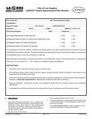
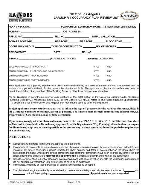
CITY of Los Angeles<br />
<strong>LARUCP</strong> R-1 OCCUPANCY PLAN REVIEW LIST<br />
PLAN CHECK NO. PLAN CHECK EXPIRATION DATE: 18 months from submittal date<br />
PCIS# (s): _____________________________ JOB ADDRESS:<br />
APPLICANT TEL. NO. INITIAL VALUATION<br />
SQUARE FOOTAGE USE ZONE FIRE ZONE FLOOD ZONE<br />
OCCUPANCY GROUP TYPE OF CONSTRUCTION NO. OF STORIES<br />
REVIEWED BY: _________________<br />
DATE: ______________ TEL. NO. : __________________<br />
E-MAIL: _______________________@LADBS.LACITY.ORG Website: LADBS.ORG<br />
BUILDING SPRINKLERS THROUGHOUT? 9 YES 9 NO<br />
SPRINKLER USED IN LIEU OF ONE-HOUR CONSTRUCTION? 9 YES 9 NO<br />
SPRINKLER USED FOR AREA INCREASE? 9 YES 9 NO<br />
SPRINKLER USED FOR STORY INCREASE? 9 YES 9 NO<br />
Your application for a permit, together with plans and specifications, has been examined and you are advised that the<br />
issuance of a permit is withheld for the reasons hereinafter set forth. The approval of plans and specifications does not<br />
permit the violation of any section of the Building Code, or other local ordinance or state law.<br />
NOTE: Numbers in parenthesis refer to Code sections of the 2001 edition of the California Building Code, (T=Table),<br />
Plumbing Code (P.C.), Mechanical Code (M.C.) or Fire Code (F.C.). N.D.S. refers to The National Design Specifications.<br />
(*) Corrections used by the City of Los Angeles that may not be used by other municipalities.<br />
Project applicants/representatives are advised to initiate the sign-off processes for the required clearances, listed in<br />
the Clearance Summary Worksheet, as soon as possible. The time to obtain the sign-off from some departments, i.e.,<br />
Department of City <strong>Plan</strong>ning, may be time-consuming.<br />
If you cannot comply with the plan check corrections circled under PLANNING & ZONING of this correction sheet,<br />
and instead, wish to obtain a discretionary approval from the Department of City <strong>Plan</strong>ning, please initiate the request<br />
for discretionary approval as soon as possible as the process may be time-consuming due to the probable requirement<br />
of a public hearing.<br />
INSTRUCTIONS<br />
! Corrections with circled item numbers apply to this plan check.<br />
! Incorporate all comments as marked on checked set of plans and calculations and this corrections sheet. In the left hand<br />
margin of the circled corrections, please indicate the sheet number and detail or note number on the plans where the<br />
corrections are made. Once all the circled corrections and additional corrections have been addressed, contact the plan<br />
check engineer to schedule a verification appointment to demonstrate compliance with all the corrections.<br />
! Bring the original checked set of plans and calculations along with this correction sheet to the verification appointment.<br />
Do not schedule a verification until all corrections have been addressed.<br />
! Incomplete, indefinite or faded drawings or calculations will not be accepted.<br />
! The plan check engineer will only be available for conference and telephone calls between the hours of and<br />
on the following days:<br />
. Appointments are recommended.<br />
LADBS-Corr.Lst.18 (6/2003)<br />
Page 1 of 23<br />
www.<strong>ladbs</strong>.org
A. APPLICATION<br />
1. Obtain the building Permit prior to expiration or file an<br />
extension with an additional fee of $ .<br />
2. Valuation is low. It should be $ .<br />
Pay a supplemental plan check fee of $ .<br />
3. Art development fees are applicable to the proposed hotel. ( 107.4.6)<br />
4. Complete the permit application form to show the legal<br />
description, building area, street address, owner, designer,<br />
occupancy group, type of construction, fire zone,<br />
.<br />
5. A separate application and permit(s) is/are required for:<br />
a. Retaining walls<br />
b. Block walls (>3.5')<br />
c. Signs<br />
d. Swimming pools<br />
e. Fire sprinkler systems<br />
f. Each separate structure<br />
g. Electrical work<br />
h. Mechanical work<br />
i. Plumbing work<br />
* j. Grading (Backfill)(Removal/Recompaction)(Site grading)<br />
* k. Shoring<br />
* l. Demolition work<br />
* m. ( )<br />
6. Obtain proof of lot cut date prior to___________<br />
(After 6-1-46 comply to zone minimums.)<br />
(After 7-29-62 obtain Certificate of Compliance<br />
from City <strong>Plan</strong>ning.)<br />
7. A recorded affidavit is required for ( ). The<br />
affidavit must be approved by the plan check engineer prior to<br />
recording.<br />
8. Provide copies of the following documents which appear on<br />
this parcel: ( ).<br />
For information on how to obtain copies of affidavits,<br />
please call Building and Safety Records Section, Metro<br />
office (213) 482-6899 or Van Nuys Office (818) 374-4390.<br />
For all other City <strong>Plan</strong>ning documents contact the<br />
Department of City <strong>Plan</strong>ning at (213) 978-1259, or fax<br />
request to (213) 978-1263. Additional corrections and/ or<br />
Clearances may follow upon review of the documents.<br />
9. Provide a copy of the Certificate of <strong>Occupancy</strong> and/or<br />
building permit showing the permitted use and required<br />
parking.<br />
10. Show the legal description, building area, occupancy<br />
group(s), use(s), type of construction, number of story(s),<br />
fire zone, lot size, lot area and height on the first sheet or<br />
title sheet of plans.<br />
11. Comply with protection of adjoining property by giving a 30<br />
day written notice (by certified mail) of attached letter to<br />
adjacent property owners, of intent to excavate where<br />
excavation is deeper than the foundation of adjoining building<br />
and located closer to property line than the depth of<br />
excavation.<br />
12. The permit application must be signed by the property owner,<br />
or licensed contractor, or authorized agent at the time the<br />
permit is to be issued:<br />
a. For owner-builder permits: Owner’s signature must be<br />
verified by notarization or personal identification.<br />
b. For contractor building permits: Prior to the issuance<br />
of a building permit, the contractor shall have the following:<br />
I. Certificate of workers Compensation Insurance<br />
made out to the Contractors State License Board.<br />
II. Notarized letter of authorization for agents.<br />
III.Copy of Contractors State License or pocket ID.<br />
* IV. Copy of ( ) City business tax<br />
registration certificate or a newly paid receipt<br />
for one.<br />
13. (Soil)(Foundation)(Geology) report(s) must be approved by<br />
City Grading Section. Provide copy of approved report and<br />
Department approval letter. Show compliance with all the<br />
requirements of the reports and the approval letter conditions.<br />
14. Provide temporary shoring plans for excavations that remove<br />
the lateral support from a public way or an existing building.<br />
Excavations adjacent to a public way require Public Works<br />
approval prior to issuance of building permit.<br />
B. REFERRALS<br />
1. Please see the attached clearance summary worksheet for the<br />
clearance required prior to issuance of building permit.<br />
Project applicants/representatives are advised to<br />
initiate the sign-off processes for these clearances<br />
as soon as possible. The time to obtain the signoff<br />
from some departments, i.e., Department of<br />
City <strong>Plan</strong>ning, may be time-consuming. Read<br />
the comments attached to the clearance, if any,<br />
as they often contain important and useful<br />
information.<br />
2. Call ( ) ___________ for information on obtaining the<br />
required clearance for ______________ Specific <strong>Plan</strong>,<br />
_______________ HPOZ, ______________ CDO, and<br />
_______________ POD. Not all projects can be cleared the<br />
same day and an appointment may be necessary.<br />
LADBS-Corr.Lst.18 (6/2003)<br />
Page 2 of 23<br />
www.<strong>ladbs</strong>.org
3. Prior to issuance of building permit, obtain approval from:<br />
a). California Division of Occupational Safety and<br />
Health(Cal-OSHA) for (excavations exceeding 5-ft height<br />
where worker descends) (Building over 3-story’s or 35-ft<br />
height). 350 W. 4 th St. Ste 850, Los Angeles, CA<br />
(213)576-7451 or 6150 Van Nuys Bl, Rm 405, Van Nuys,<br />
CA (818)901-5403<br />
b). Los Angeles County Health Department for: (food<br />
establishment)(swimming pool)(potable chemical<br />
toilet)(water well construction/monitoring/destruction)<br />
3530 Wilshire Bl, 9 th floor Los Angeles, CA (213)351-<br />
7352<br />
6851 Lennox Ave, 3 rd floor, Van Nuys, CA (818)902-4470<br />
6053 Bristol Parkway, 2 nd floor, Culver City, CA<br />
(310)665-8483<br />
122 W. 8 th St. Rm 20-A, San Pedro, CA (310)519-6081<br />
Admin HQ: 5050 Commerce Dr., Baldwin Park, CA<br />
(626)430-5560<br />
c). Dept. of Conservation, Division of Oil and Gas (DOG) for<br />
project on land with an abandoned oil well. 5816<br />
Corporate Ave., Room 200, Cypress, CA (714)816-6847.<br />
4. Rough grading approval is required before a building permit<br />
can be issued.<br />
5. Parcel Map/Tract Map _______________ must be recorded<br />
before a permit can be issued. Submit a copy of the recorded<br />
map.<br />
6. Submit a copy of CUP, plot plan number .<br />
7. For energy insulation requirements, see attached sheet.<br />
Submit energy calculations for the shell. The energy<br />
Certificate of Compliance shall be a part of the plans.<br />
D. BEST MANAGEMENT PRACTICES<br />
1. Storm water provisions are required to be shown on the plans<br />
in accordance with the following requirements of exception<br />
14, section 106.4.1.<br />
a. Construction Projects - Small construction sites with less<br />
than two acres of disturbed soil and not located in<br />
designated hillside areas nor in or adjacent to an<br />
environmental sensitive areas shall implement the Best<br />
Management Practices (BMP) identified on attachment<br />
“A” entitled “Minimum Requirements for Construction<br />
Projects/Certification Statement”. In addition, attachment<br />
“A” shall be signed by the owner or an authorize agent of<br />
the owner.<br />
b. Priority Projects - Medium construction sites of two or<br />
more acres and up to, but less than five acres of disturbed<br />
soil shall prepare a local Storm Water Pollution Prevention<br />
<strong>Plan</strong> (SWPPP). The plans shall show all BMPs necessary<br />
to control and prevent discharge of sediments and other<br />
pollutants generated by the construction activities specific<br />
to each site, see Attachment “B” . Included as part of the<br />
SWPPP, the owner or authorized agent of the owner must<br />
sign the certification statement, attachment “1", and<br />
incorporate attachment “2" into the SWPPP. All sediment<br />
and pollution prevention measures identified on the plans<br />
shall be in place and maintained for the duration of the<br />
project or until no longer deemed necessary by the<br />
responsible City/County inspector.<br />
c. General Construction Permit Projects - Large construction<br />
sites with five acres or more disturbed soil are required to<br />
comply with the State General Permit for Construction<br />
Activity. This permits requires the submittal of a Notice of<br />
Intent to the State Water Resources Control Board and<br />
development of a state Storm Water Pollution Prevention<br />
<strong>Plan</strong>. The developer is required to show proof of these<br />
submittals.<br />
2. Note: An Wet Weather Erosion Control <strong>Plan</strong> (WWECP),<br />
utilizing sediment and erosion control BMPs, for projects that<br />
will leave disturb soil during the rainy season (October 1 to<br />
April 15) is required. The WWECP must be prepared, for<br />
projects that have already broken ground, not less than 30<br />
days priors to the beginning of each rainy season during which<br />
soil will be disturbed, and implemented throughout the entire<br />
rainy season. A copy of the WWECP shall be kept on the<br />
project site at all times beginning 30 days prior to the start of<br />
the rainy season through the end of the rainy season. For<br />
projects that will begin construction during the rainy season,<br />
the WWECP must be available 30 days before construction<br />
commences. The WWECP must be submitted to the Bureau of<br />
Engineering, Public Works for review and approval. The<br />
WWECP is not a requirement for the issuance of a building or<br />
grading permit.<br />
D. SITE PLAN<br />
1. The address of the building and the name and address of the<br />
owner and designer are required on the first sheet of the plans.<br />
2. Provide fully dimensioned plot plan to scale, in ink, or copied<br />
to the application plot plan sheet provided. Show building<br />
lines, easements, lot size, zone boundaries, highway<br />
dedication lines, street center line, alley, parking spaces, area<br />
separation walls, and location of all buildings. (Show type of<br />
construction, number of stories and use of all buildings.)<br />
Must agree with plot plan shown on plans. (106.3.2.1)<br />
3. Building projections into public properties must comply with<br />
Chapter 32.<br />
4. Note on the plans: "Temporary pedestrian protection shall be<br />
provided as required by Section 303.7<br />
5. Show on site plans finish floor, natural and grade elevations.<br />
LADBS-Corr.Lst.18 (6/2003)<br />
Page 3 of 23<br />
www.<strong>ladbs</strong>.org
6. Show location and distance of active and abandoned oil wells<br />
with respect to building perimeter.<br />
E. *PLANNING & ZONING<br />
If you cannot comply with circled corrections in this<br />
section, and instead, wish to obtain a discretionary<br />
approval from the Department of City <strong>Plan</strong>ning,<br />
please initiate the request for discretionary approval<br />
as soon as possible as the process may be timeconsuming<br />
due to the probable requirement of a<br />
public hearing.<br />
1. Number of dwelling units is excessive for lot area in the<br />
( ) Zone.<br />
2. A basement containing habitable rooms is considered a story<br />
for side yard, rear yard and number of stories.<br />
12.21C1(l), 12.21.1A8.<br />
3. Yards- Provide and dimension: ____________ front yard;<br />
____________ side yard; ___________ rear yard.<br />
4. Building exceeds (45' height) (3 times buildable area) limit(s)<br />
of Height District #1. Not limited as to number of stories.<br />
12.21.1.<br />
5. Provide ( ) paved parking spaces. A minimum of 1 space<br />
per unit shall be standard stall. 12.21A4, 5.<br />
6. Maximum driveway slope is 20%. Grade details and<br />
transition slopes are required where slope exceeds 12½%.<br />
Maximum driveway cross slope is 10%. Maximum slope<br />
within parking area is 5%. 12.21A5(g).<br />
7. Parking is not permitted in the required front yard, and 5'<br />
side yard along the side street lot line of a corner lot.<br />
12.21A6(a).<br />
8. Automobiles are not permitted to back onto a public street or<br />
sidewalk. 12.21A5(i)1.<br />
9. Provide parking design per the attached Building Department<br />
Standards. <strong>Plan</strong>s shall be drawn to an appropriate scale<br />
(suggest 1/8"=1') and be fully dimensioned to show aisle<br />
widths (including Fig 3 circulation driveway), stall widths<br />
(including increases for obstructions and end aisle stalls).<br />
12.21A5<br />
10. Walls - Parking and turning areas within 15' of a property line<br />
must be enclosed by a 5'-9" high wall*. A 3' high wall* is<br />
required where within 15' of the sidewalk. 12.21A6(d), (e),(f).<br />
*A concrete or masonry construction is required for parking<br />
areas.<br />
11. Maintain minimum 10'(20') separation between buildings.<br />
12.21C2(a).<br />
12. Provide a minimum 10'(12') passageway from the street to<br />
each dwelling unit and guest room. 12.21C2(b).<br />
13. Maximum eave projection of ( ) inches allowed in<br />
( ). 12.22C20(b).<br />
14. Projection of ( ) into the<br />
( ) yard/passageway<br />
(not permitted) (limited to<br />
). 12.22C2.<br />
15. (Fences) (<strong>Plan</strong>ters) (Retaining walls) shall not exceed a height<br />
of ( ) ft. above the natural ground level in required<br />
( ) yard. 12.22C20(f).<br />
16. Provide 30" minimum clear access around main building(s)<br />
and accessory living quarters. 12.22C20(l).<br />
17. Comply with the provisions of Specific <strong>Plan</strong> (<br />
).<br />
18. Zoning Information File No. ( ) requires that<br />
___________________________________________________<br />
___________________________________________________<br />
____________________________________________________<br />
19. For hotels and motels, provide a 400 sq ft loading zone with<br />
a 20' minimum length along the alley. 12.21C6(c).<br />
20. Provide a recycling room or area for 4 or more units.<br />
12.21A19(c).<br />
13. For development of over 5 units, Provide a total minimum<br />
usable open space on site of: 100 sq ft for each unit smaller<br />
than 3 habitable rooms; 125 sq ft for each unit of 3 habitable<br />
rooms; and 175 sq ft for each unit over 3 habitable rooms. (A<br />
kitchen is not counted in this section as a habitable room.)<br />
Sec.12.21G2<br />
a) Common open space shall be open to the sky and have no<br />
structures that project into the open space area and readily<br />
accessible to all residents of the site. Sec. 12.21G2(a)<br />
b) 400 ft 2 -15' min. Common open space shall have a<br />
minimum of 400 sf. with no horizontal dimension less than<br />
15 ft. Sec. 12.21G2(a)(1)(iii)<br />
c) At Grade Level: Common open space shall be located at<br />
grade level or first habitable room level, except for<br />
developments in R3, R4 and/or R5. Sec.12.21G2(a)(1)(iv).<br />
d) Obtain City <strong>Plan</strong>ning Approval: 25% of the common<br />
open space to be landscaped according to City <strong>Plan</strong>ning<br />
Standards.12.21G2(A)(3).<br />
22. Accessory building is not permitted on front half of lot,<br />
except when located minimum 55-ft from the front line or<br />
private garage located on sloping lot in accordance with<br />
12.21C5(l).<br />
12.21C5(b).<br />
23. Provide minimum 5-ft setback from rear property line ( 10'<br />
from alley center line ) and ( )_setback from side<br />
property line for accessory building containing recreation<br />
room or accessory living quarters. 12.21C5(e), (f), (g)<br />
LADBS-Corr.Lst.18 (6/2003)<br />
Page 4 of 23<br />
www.<strong>ladbs</strong>.org
24. No mezzanine is permitted within a recreation room.<br />
12.03<br />
PLANS & CALCULATIONS<br />
F. ACCESSIBILITY REQUIREMENTS<br />
1. For the State of California requirements, see separate<br />
correction sheet.<br />
G. SECURITY REQUIREMENTS<br />
Compliance with Chapter 67* is required at door(s) to<br />
individual units, at exterior doors to the main building, at<br />
doors between the R-1 and S-3 occupancies and at all doors to<br />
the Group B/F/M/R/S occupancy.<br />
General:<br />
1. All entry doors to dwelling units or guest rooms shall be arranged<br />
so that the occupant has a view of the area immediately outside<br />
the door without opening the door. Such view may be provided<br />
by a door viewer, through windows located in the vicinity of the<br />
door or through view ports in the door or adjoining wall. (6706)<br />
2.. Screens, barricades, or fences made of material which preclude<br />
human climbing shall be provided at every portion of every roof,<br />
balcony, or similar surface which is within 8 ft. of the utility pole or<br />
similar structures. (6707)<br />
Doors:<br />
3. Wood flush-type doors shall be 1 3/8" thick minimum with solid<br />
core construction. 91.6709.1 - Door stops of in-swinging doors shall<br />
be of one-piece construction with the jamb or joined by rabbet to the<br />
jamb. (6709.4)<br />
4. Every door in a security opening for an apartment house shall be<br />
provided with a light bulb (60 watt min.) At a maximum height of 8<br />
feet on the exterior. (6708)<br />
5. All pin-type door hinges accessible from outside shall have nonremovable<br />
hinge pins. Hinges shall have min. 1/4" dia. steel jamb stud<br />
with 1/4" min. protection. The strike plate for latches and holding<br />
device for projecting dead bolts in wood construction shall be secured<br />
to the jamb and the wall framing with screws no less than 2-1/2" long.<br />
(6709.5, 6709.7)<br />
6. Provide dead bolts with hardened inserts; deadlocking latch with<br />
key-operated locks on exterior. Locks must be openable from inside<br />
without key, special knowledge or special effort (latch not required in<br />
B, F, and S occupancies. (6709.2)<br />
7. Straight dead bolts shall have a min. throw of 1" and an<br />
embedment of not less than 5/8", and a hook-shaped or an<br />
expanding-lug deadbolt shall have a minimum throw of 3/4".<br />
(6709.2)<br />
8. The use of a locking system which consists of a deadlocking latch<br />
operated by a doorknob and a deadbolt operated by a non-removable<br />
thumb turn which is independent of the deadlocking latch and which<br />
must be separately operated, shall not be considered as a system which<br />
requires special knowledge or effort when used in dwelling units. The<br />
door knob and the thumb turn which operates the deadbolt shall not be<br />
separated by more than 8 inches.<br />
9. Wood panel type doors must have panels at least 9/16 in. thick<br />
with shaped portions not less than 1/4 in. thick and individual panels<br />
LADBS-Corr.Lst.18 (6/2003)<br />
Page 5 of 23<br />
must be no more than 300 sq. in. in area. Mullions shall be considered<br />
a part of adjacent panels except mullions not over 18 inches long may<br />
have an overall width of not less than 2 inches. Stiles and rails shall be<br />
of solid lumber in thickness with overall dimensions of not less than<br />
1 3/8 inches and 3 inches in width. (6709.1 item 2 )<br />
10. Sliding doors shall be provided with a device in the upper channel<br />
of the moving panel to prohibit raising and removing of the moving<br />
panel in the closed or partially open position. (6710)<br />
11. Sliding glass doors shall be equipped with locking devices and<br />
shall be so constructed and installed that they remain intact and<br />
engaged when subjected to the tests specified in section 6717.1.<br />
12. Metal or wooden overhead or sliding doors shall be secured with<br />
a cylinder lock, padlock with a min. 9/32" diameter hardened steel<br />
shackle and bolted, hardened steel hasps, metal slide board, bolt or<br />
equivalent device unless secured electrically operated. (6711)<br />
13. Provide metal guides at top and bottom of metal accordion grate<br />
or grille-type doors and cylinder locks or padlocks. Cylinder guards<br />
shall be installed on all cylinder locks whenever the cylinder projects<br />
beyond the face of the door or is otherwise accessible to gripping<br />
tools. (6712)<br />
Glazing:<br />
14. In B, F, M, and S occupancies, panes of glazing with at least one<br />
dimension greater than 5 in. but less than 48 in, shall be constructed<br />
of tempered or approved burglary-resistant material or protected with<br />
metal bars or grilles. (6714)<br />
15. Glazed openings within 40" of the door lock when the door is in<br />
the closed position, shall be fully tempered glass or approved burglary<br />
resistant material, or shall be protected by metal bars, screens or grills<br />
having a maximum opening of 2". The provisions of this section shall<br />
not apply to view ports or windows which do not exceed 2" in their<br />
greatest dimensions. (6713)<br />
Windows:<br />
16. Louvered windows shall be protected by metal bars or grills with<br />
openings that have at least one dimension of 6" or less, which are<br />
constructed to preclude human entry. (6715.3)<br />
17. Other openable windows shall be provided with substantial<br />
locking devices. In B, F, M and S occupancies, such devices shall be<br />
glide bars, bolts, cross-bars, and/or padlocks with minimum 9/32"<br />
hardened steel shackles and bolted, hardened steel hasps. (6715.2)<br />
18. Sliding windows shall be provided with a device in the upper<br />
channel of the moving panel to prohibit raising and removing of the<br />
moving panel in the closed or partially open position. ( 6715.1)<br />
19. Sliding windows shall be equipped with locking devices and<br />
shall be so constructed and installed that they remain intact and<br />
engaged when subjected to the tests specified in (6717.2)<br />
20. Any release for metal bars, grills, grates or similar devices<br />
constructed to preclude human entry that are installed shall be located<br />
on the inside of the adjacent room and at least 24 inches from the<br />
closest opening through such metal bars, grills, grates or similar<br />
devices that exceeds two inches in any dimension. (6715.4)<br />
Openings other than Doors or Glazed Openings:<br />
21. All other openings must be protected by metal bars or<br />
grilles with openings of not less than 6 inches in one dimension.<br />
(67160<br />
13. Provide security lighting for garage and/or exterior parking<br />
area serving dwelling units or guestrooms and for recreation<br />
room, service rooms accessory to apartment houses, and at<br />
every door in a security opening. Security lighting shall have<br />
a surface illumination of 0.2 foot-candles at the floor level.<br />
www.<strong>ladbs</strong>.org
(6708, 6305, 12.21A5(k))<br />
H. SOUND REQUIREMENTS BETWEEN UNITS<br />
General<br />
In Group R Occupancies, wall and floor- ceiling assemblies<br />
separating dwelling units or guest rooms from each other and<br />
from public space such as interior corridors and service areas<br />
shall provide airborne sound<br />
insulation for walls, and both airborne and impact sound<br />
insulation for floor-ceiling assemblies. All such separating walls<br />
and floor-ceiling assemblies shall provide an airborne sound<br />
insulation equal to that required to meet a sound transmission<br />
class (STC) f 50 (45 if field tested). All separating floor-ceiling<br />
shall provide impact sound insulation equal to that required to<br />
meet an impact insulation class (IIC) of 50 (45 if field tested)<br />
(1208A.2).<br />
EXCEPTION: Impact sound insulation is not required for floorceiling<br />
assemblies over non-habitable rooms or spaces not<br />
designed to be occupied, such as garages, mechanical rooms or<br />
storage areas.<br />
1. Identify all sound rated partitions on the floor plans.<br />
2. Provide construction details for sound rated wall<br />
assemblies.<br />
3. Provide construction details for sound rated floor-ceiling<br />
assemblies<br />
4. All penetration into sound rated partitions or approved<br />
permanent resilient sealant. ~<br />
5. All rigid conduit, ducts, plumbing pipes, appliance vents<br />
located in sound assemblies shall be isolated from the building<br />
construction by means of resilient sleeves, mounts or minimum<br />
1/4" thick approved resilient material. vents located in sound<br />
assemblies shall be isolated from the building construction by<br />
means of resilient sleeves, mounts or minimum 1/4" thick<br />
approved resilient material<br />
6. An approved permanent, and resilient acoustical sealant<br />
shall be provided along the joint between the floor and the<br />
separation walls. ~ floor-ceiling assemblies shall be sealed,<br />
lined or insulated with<br />
7. Carpets or similar surface material which are part of the<br />
floor-ceiling assembly must be installed and inspected before<br />
the Certificate of <strong>Occupancy</strong> is issued and may be replaced only<br />
by other floor covering that provides the required impact sound<br />
insulation. (1208A.3)<br />
8. Metal ventilating and conditioned air ducts located in sound<br />
assemblies shall be lined. (Exception: Ducts serving only exit<br />
ways, kitchen cooking facilities, and bathrooms need not be<br />
lined).<br />
9. Mineral fiber insulation shall be installed in joist spaces<br />
whenever a plumbing piping, or duct penetrates a floor-ceiling<br />
assembly or where such unit passes through the plane of the<br />
floor-ceiling assembly from within a wall. The insulation shall be<br />
installed to a point 12" beyond the pipe or duct. This<br />
requirement is not applicable to fire sprinkler pipe, gas line or<br />
electrical conduit. ~<br />
10. Electrical outlet boxes in opposite faces of separation walls<br />
shall be separated horizontally by 24" and note that back and<br />
sides of boxes will be sealed with 1/8" resilient sealant and<br />
backed by a minimum of 2" thick mineral fiber insulation. (TV,<br />
telephone and intercom outlets must be installed in boxes<br />
accordingly.)~<br />
11. The entrance doors to residential units from interior<br />
corridors are required to have a minimum STC rating of 26.<br />
(Laminated 1 3/4" solid-core doors with resilient stops and<br />
gaskets or 18 gauge insulated steel slab doors with<br />
compression seals all around, including thresholds will meet this<br />
requirement). (1208A.2).<br />
12. Wall mounted lavatories and toilets are not permitted on<br />
sound rated partitions. ~<br />
I. AREA AND OCCUPANCY<br />
1. Show on the plans the proposed number of stories, occupancy<br />
group(s), type(s) of construction and area justification for this<br />
structure. Vent shafts and courts do not count as area. The<br />
mezzanine floor area must be included in the area of the story<br />
in which it is located. The basement need not be included in<br />
the total allowable area if it does not exceed the area permitted<br />
for a one-story building. Provide an area breakdown by level.<br />
2. Exterior (court) (bearing) (nonbearing) walls within<br />
feet of property lines must be of hour<br />
construction. (503.2)<br />
3. Provide minimum 30" high parapet on the ( )<br />
exterior walls. (709.4)<br />
4. Openings in exterior (court) walls within feet of<br />
property lines (must be protected with three-fourths-hour fire<br />
assemblies) (not permitted). (503.2)<br />
5. Limit openings to 50% of the area of any exterior wall where<br />
protected openings are required. (503.2.2)<br />
6. The building as shown is a mixed-occupancy building. The<br />
sum of the ratios of the actual area for each separate<br />
occupancy divided by the total allowable area for separate<br />
occupancy must not exceed one. ( 504.3)<br />
7. A property line must be assumed between buildings on the<br />
same property(court walls) to determine wall and opening<br />
protection requirements. ( 503.3)<br />
8. The total floor area must be limited to______ square feet,<br />
including increase of _______ percent for ______________-<br />
foot yards, 100 percent for multistory buildings and doubling<br />
(tripling in one-story buildings) for sprinkler through-out.<br />
(504 & 505)<br />
8. The floor area of the 2 nd floor between area separation walls<br />
shall not exceed 3000 sq. ft., otherwise 1 hour construction<br />
shall be provided. (310.2.2)<br />
9. Unobstructed yards of feet must be maintained on<br />
sides of the building to permit a Percent<br />
floor area increase. (505)<br />
10. Complete and return the attached yard Affidavit as part of the<br />
area justification.<br />
LADBS-Corr.Lst.18 (6/2003)<br />
Page 6 of 23<br />
www.<strong>ladbs</strong>.org
11. Clearly identify on the plans, provide details for and show<br />
the required opening protection for the following:<br />
a. The 1-hour occupancy separation between the R-1 and<br />
Occupancies.<br />
(302.3,T-3-B)<br />
b. The 3-hour occupancy separation between the R-1 and<br />
S-3 occupancies. (302.3,311.2.2.1,T-3-B)<br />
c. The ____hour area separation wall(s). (504.6)<br />
d. Show location of all area separation walls on plot,<br />
floor, foundation, and roof plans.<br />
12. Show maximum height of the structure on all elevation views.<br />
13. This structure is of type construction. Show on the<br />
plans the required roof, exterior wall<br />
construction, structural frame protection, and floor<br />
construction.<br />
(T-6-A)<br />
14. Ducts through two-hour area separation walls require dampers.<br />
15. Projections beyond the exterior wall must not extend beyond:<br />
a. A point one-third the distance to the property line from an<br />
exterior wall. (503.2.1)<br />
b. A point one-third the distance from an assumed vertical<br />
plane located where fire- resistive protection of openings<br />
is first required due to location on property.<br />
(503.2.1 & 705)<br />
c. A point more than 12" into area when openings are<br />
prohibited. ( 503.2.1)<br />
16. Exterior exit stairways, balconies and ramps must not project<br />
into yards where wall openings are not permitted or must be<br />
protected.<br />
17. Horizontal occupancy separation must be supported with a<br />
structural system having equivalent fire-resistive protection.<br />
(302.2)<br />
18. Vertical occupancy separations must afford a complete<br />
separation and must extend through underfloor and attic areas,<br />
including areas where fire-resistive ceilings are specified.<br />
( 302.2)<br />
19. Provide detail to show that (2) hour area separation<br />
walls will comply with Section 504.6<br />
a. Extend vertically from the foundation to a point 30 inches<br />
above the roof. (504.6.4)<br />
b. Total width of all openings limited to 25 percent of the<br />
wall length in the story under consideration. (504.6.2)<br />
c. All openings to be protected with fire assemblies having a<br />
fire-resistive rating of (1-1/2) (3) hours.<br />
d. Ducts through area separation walls should be avoided. If<br />
allowed duct penetrations should be protected as required<br />
in 713.11.<br />
20. Fire blocking must be provided in accordance with Section<br />
708.2.1 in the following locations:<br />
a. In concealed spaces of stud walls and partitions, including<br />
furred spaces, at the ceiling and floor levels.<br />
b. In concealed spaces of stud walls and partitions, including<br />
furred spaces, at 10-foot intervals along the length of the<br />
wall.<br />
c. At all interconnections between concealed vertical and<br />
horizontal spaces such as occur at soffits, drop ceilings and<br />
covered ceilings.<br />
d. In concealed spaces between stair stringers at the top and<br />
bottom of the run and between studs along and in line with<br />
the run of stairs if the wall under the stairs is unfinished.<br />
e. In openings around vents, pipes, ducts, chimneys,<br />
fireplaces and similar openings which afford a passage for<br />
fire at ceiling and floor levels, with noncombustible<br />
materials.<br />
21. Draft stops must be provided in the following locations:<br />
a. In the attics, mansards, overhangs, false fronts set out from<br />
walls and similar concealed spaces, and in floor-ceiling<br />
assemblies. Draft stops shall be in line with walls<br />
separating individual dwelling units and guest rooms from<br />
each other and from other uses. The separated attic space<br />
cannot exceed 3000 sq. ft and the greatest horizontal<br />
dimension cannot exceed 60 ft. (708.3.1-1.2, 708.3.1.2.1,<br />
1505.7)<br />
b. Show draft-stop construction on the plans. Draft-stopping<br />
materials must not be less than ½-inch gypsum board, 3/8-<br />
inch plywood, 3/8-inch Type 2-M particle board or other<br />
materials approved by the building department. Draftstopping<br />
must be adequately supported. ( 708.3.1.3)<br />
22. Members providing vertical support for concrete or masonry<br />
in upper story require 1-hour fire resistive protection. ( 704.4)<br />
23. Exterior stairs must be constructed of As<br />
specified in Section 602.4. (603.4) (604.4) (605.4) (606.4)<br />
24. No openings other than required exits are permitted in walls<br />
of exit passageways. The passageways must be of<br />
- hour fire-resistive construction. Openings must be<br />
protected with labeled three-fourths-hour fire assemblies.<br />
( 1011.1)<br />
25. An automatic sprinkler system is required in all buildings 3<br />
stories or more in height or containing 5 or more dwelling<br />
units. Note on plan sheet “This building and garage<br />
must be equipped with an automatic fire extinguishing<br />
system.” (904.2.9)<br />
LADBS-Corr.Lst.18 (6/2003)<br />
Page 7 of 23<br />
www.<strong>ladbs</strong>.org
26. Exceptions to, or reductions in building code requirements<br />
based on the installation of automatic fire extinguishing<br />
system is not allowed when utilizing NFPA-13R type<br />
residential sprinkler system allowed for R- occupancies four<br />
stories or less in height. 904.1.3, 505.3, 506, 508.<br />
27. Envelope ceilings must satisfy the following conditions of<br />
Section 704.2.6<br />
a. Envelope ceilings must not be used to provide fire<br />
protection for beam and girders supporting more<br />
than one floor or roof.<br />
b. Columns must be individually fire protected.<br />
c. The areas of openings for copper, sheet steel and ferrous<br />
plumbing pipes must be limited to 100 square inches in<br />
each 100 square feet of ceiling area. Duct openings<br />
must be protected by approved ceiling fire dampers.<br />
d. Individual electrical outlet boxes must be of steel and<br />
not greater than 16 square inches in area.<br />
28. Combustible materials framed into a fire-resistive wall must<br />
have one half the required wall thickness as end protection.<br />
( 709.2)<br />
29. In fire-resistive exterior wall construction, the fire-resistive<br />
rating must be maintained for such walls passing through attic<br />
areas. ( 709.3)<br />
30. Penetrations in walls requiring protected openings must be fire<br />
stopped with an approved material in accordance with Section<br />
709.6. Space between penetrating materials (described below)<br />
must be designed to prevent the movement of hot flame or<br />
gases.<br />
a. Copper or ferrous pipes or conduits may penetrate the<br />
walls or partitions, provided they are fire stopped.<br />
b. Openings for steel electrical outlet boxes not exceeding<br />
16 square inches are permitted provided openings do not<br />
aggregate more than 100 square inches or 100 square<br />
feet of wall or partitions. Outlet boxes on opposite sides<br />
of walls or partitions must be separated by a horizontal<br />
distance of 24 inches.<br />
c. Where walls are penetrated by the other materials or<br />
where larger openings are required than permitted in (b)<br />
above, they must be qualified by tests conducted in<br />
accordance with Section 703.2.<br />
32. Show the location on the plans.<br />
Class I, II or III standpipe (dry, wet, combination) are<br />
required in this building. Hose size is respectively 2 ½",<br />
1 ½" outlets for the sprinkler system. (904.5.1 thru 5, T-9-A)<br />
33. The Type I parking structure permitted by section 311.2.2 is<br />
a story rather than a basement. This structure is 4 stories in<br />
height and requires sprinklers throughout (904.2.2-5)<br />
.<br />
34. This structure has Atrium(s). Show that the<br />
requirements of Section 402 are satisfied. (402.1 thru 10)<br />
35. All openings in an exterior wall below and within 10 ft.<br />
measured horizontally, of an exterior exit stairway serving<br />
buildings over two stories in height shall be protected by fixed<br />
or self-closing assembly having 3/4 -hr. fire protection rating,.<br />
Openings may be unprotected when two separated exterior<br />
stairways serves an exterior exit balcony. (1006.3.3.3)<br />
36. Pressurized enclosures are required for all exits in buildings<br />
having floors used for human occupancy located more than 75<br />
ft. above the lowest level of Fire Department vehicle access.<br />
(1005.3.3.7)<br />
37. The exit passageway requires hour construction<br />
for walls, floor and ceiling. Walls shall be without openings<br />
except for required exits. Exit openings through enclosing<br />
walls shall be ______ hour rated. (1005.3.4.3, 1005.3.4.4)<br />
J. MEANS OF EGRESS<br />
1. In determinating the occupant load, all portions of a building<br />
shall be presumed to be occupied at the same time except for<br />
accessory use areas that ordinarily are used only by persons<br />
who occupy the main area. ( 1003.2.2.2.1)<br />
2. For areas without fixed seats, the occupant load shall not be<br />
less than the number determined by dividing the floor area<br />
under consideration by the occupant load factor. (Table 10-A)<br />
3. For areas having fixed benches or pews, the occupant load<br />
shall not be less than the number of seats based on one person<br />
for each 18 inches (457 mm) of length of pew or bench.<br />
Where fixed booths are used in dining areas, the occupant<br />
load shall be based on one person for each 24 inches (610<br />
mm) of booth length. Where fixed benches, pews or booths<br />
are curved, the larger radius shall determine the booth length.<br />
(1003.2.2.2.3)<br />
31. Smoke and fire dampers must be installed in the following<br />
locations per Section 713.11:<br />
a. Duct penetrations of area or occupancy separation walls<br />
with ratings of two hours or less.<br />
b. Ducts passing through horizontal exit walls.<br />
c. Ducts penetrating shafts (see exception).<br />
d. Ducts penetrating fire-resistive elements of fire-rated<br />
corridor walls. See exception for steel ducts with no<br />
openings into corridor.<br />
LADBS-Corr.Lst.18 (6/2003)<br />
Page 8 of 23<br />
4. All exit doors serving an occupant load of 10 or more, along<br />
the path of exit travel anywhere in a means of egress system<br />
shall comply with the requirements of Section (1003.3.1)<br />
a. Revolving, sliding and overhead doors shall not be used<br />
as required exit doors. (1003.3.1.2)<br />
www.<strong>ladbs</strong>.org
. All required exit doors shall be not less than 3 ft. wide<br />
6'-8" high, shall have a clear exit way width of not less<br />
than 32" and shall be capable of opening 90 degrees.<br />
The maximum door leaf width is 4 feet when serving an<br />
occupant load of 10 or more. (1003.3.1.3a) & (1003.3.1.4)<br />
c. Exit doors shall be of the pivoted, balanced or sidehinged<br />
swinging type. (1003.3.1.5)<br />
5. Swing door(s) in the direction of travel. OL>50<br />
(1003.3.1.5)<br />
6. The path of exit travel to and within exits in this building shall<br />
be identified by exit signs conforming to the requirements of<br />
Section 1003.2.8. Exit signs shall be readily visible from any<br />
direction of approach. Exit signs shall be located as necessary<br />
to clearly indicate the direction of egress travel. No point<br />
shall be more than 100 feet (30480 mm) from the nearest<br />
visible sign. (1003.2.8.2)<br />
7. Exit signs shall be internally or externally illuminated. When<br />
the face of an exit sign is illuminated from an external source,<br />
it shall have an intensity of not less than 5 foot candles (54<br />
(Ix)) from either of two electric lamps. Internally illuminated<br />
signs shall provide equivalent luminance and be listed for the<br />
purpose. (1003.2.8.4)<br />
8. The exit signs shall also be connected to an emergency<br />
electrical system provided from storage batteries, unit<br />
equipment or an on-site generator set, and the system shall be<br />
installed in accordance with the Electrical Code. For high-rise<br />
buildings, see Section 403. (1003.2.8.5)<br />
14. Elevators or escalators shall not be used as a required means<br />
of egress component. (1003.2.7)<br />
15. Exit doors shall be openable from the inside without the use<br />
of a key, special knowledge or effort. Flush bolts or surface<br />
bolts are prohibited. “Applies also to exit gates”. The<br />
unlatching of any leaf shall not require more than one<br />
operation. (1003.3.1.8)<br />
16. Show that the exit hardware on the exterior exit doors of this<br />
building satisfies the requirements of Section 1003.3.1.9.<br />
17. Double-acting door must not be used as exits where serving an<br />
occupant load of more than 100 (the door is part of a fire<br />
assembly) (the door is a part of a smoke- and draft-control<br />
assembly) (panic hardware is required or provided).<br />
(1003.3.1.5)<br />
18. Double-acting doors must have a view panel of not less than<br />
200 square inches. (1003.3.1.5)<br />
19. This structure has ramps. Provide enough details<br />
to show that the width, slope, landings and handrails satisfy<br />
the requirements of section 1003.3.4. (1003.1.3.1.6)<br />
20. Exiting through more than one intervening room is not<br />
permitted for an occupant load of more than 10. (1004.2.2)<br />
21. Post a sign adjacent to the required main exit door with 1"<br />
lettering stating: “ THIS DOOR MUST REMAIN<br />
UNLOCKED DURING BUSINESS HOURS.” Main exit<br />
only. (1003.3.1.8)<br />
9. The power supply for means of egress illumination shall<br />
normally be provided by the premises of electrical supply. In<br />
the event of its failure, illuminator shall be automatically<br />
provided from an emergency system for Group I, Divisions<br />
1.1 and 1.2 Occupancies and for all other occupancies where<br />
the means of egress system serves an occupant load pf 100 or<br />
more. (1003.2.9.2)<br />
10. Exits must have a minimum separation of one half the<br />
maximum overall diagonal of the building or area served<br />
measured in a straight line between exits. (1003.3)<br />
11. All exits must be continuous and terminate in a public way or<br />
exit court leading to a public way. (1001.1)<br />
12. All exterior elevation changes and interior elevation changes<br />
of 12 inches (305 mm) or more along the path of exit travel<br />
shall be made by steps, stairs or stairways conforming with<br />
the requirements of Section 1003.3.3.3 or ramps conforming<br />
with the requirements of Section 1003.3.3.4. (1003.2.6)<br />
13. Interior elevation changes of less than 12 inches (305 mm)<br />
along the path of exit travel serving an occupant load of 10 or<br />
more shall be by ramps conforming with the requirements of<br />
Section 1003.3.4. (1003.2.6)<br />
LADBS-Corr.Lst.18 (6/2003)<br />
Page 9 of 23<br />
22. <strong>Plan</strong>s must indicate the floor or landing on each side of doors<br />
is not more than 1/2 (1) inch lower than the threshold of the<br />
doorway. (1003.3.1.6)<br />
23. When a door opens over a landing, the landing shall have a<br />
length of not less than (36")(44")(60" HCD) and be not more<br />
than ½" below the threshold. 1" is OK if access is not<br />
required.<br />
(1003.3.1.6&7)<br />
24. Doors shall not project more than 7" into the required corridor<br />
width when fully opened, or more than one half into the<br />
required exit when in any position. Provide details showing<br />
compliance. (1003.3.1.7 & 1004.3.3.2)<br />
25. Dead end corridors and exit balconies must not exceed 20 feet.<br />
( 1004.2.6)<br />
26. Details of the stairway are required (1003.3.3)<br />
showing:<br />
a. A maximum 7" rise and minimum 11" run (tread).<br />
(1003.3.3.3)<br />
b. A minimum headroom over the stairs of 6'-8."<br />
(1003.3.3.3)<br />
c. A minimum (36") (44") clear width.<br />
(1003.3.3.2)<br />
www.<strong>ladbs</strong>.org
d. Handrails at all stairways with two or more risers, on<br />
the open, one or both sides.<br />
e. Handgrip portion of handrail shall not be less than 1 ¼"<br />
nor more than 2" cross-section diam. Dimension having<br />
a smooth surface with no sharp corners. (1003.3.3.6)<br />
f. A handrail height 34" to 38" above the nosing, 1 ½"<br />
clearance to the wall, 2" max. width and ends returned<br />
to the wall. The open side shall have intermediates<br />
rails or balusters spaced 4" maximum.(Less than 4"<br />
clear spacing)<br />
g. Handrails designed for 20 or 50 lbs./ft. lateral load.<br />
(T-16-B)<br />
h. One handrail extending 12" beyond the top and bottom<br />
riser.<br />
i. Stairway framing, footing, connections and bracing.<br />
j. One-hour construction for the enclosed usable space<br />
under the stairs. (1003.3.3.9)<br />
k. A stair width complying with section 1003.2.3 but not<br />
less than 44" for OL > 50, 36" for OL < 50.<br />
(1003.3.3.2)<br />
l. Stairway landing(s) (36") (44"). (1003.3.3.5)<br />
27. Spiral stairways shall not serve as required exit for an area<br />
exceeding 400 sq. ft. (1003.3.3.8.2)<br />
28. Submit drawings for spiral stairway showing compliance<br />
with Section 1003.3.3.8.2.<br />
29. Provide spiral stairway column base connection / footing<br />
detail.<br />
30. Provide sufficient details of the winding stairway to show<br />
compliance with Section 1003.3.3.8.2.<br />
31. For glass handrails and guardrails, without vertical supports,<br />
submit test report from a recognized testing agency showing<br />
that the glass and base connections shown on the plan are<br />
adequate for the required 20 or 50 lbs./ft lateral load.<br />
(T-16-B)<br />
32. The means of egress system shall have a clear height of not<br />
less than 7 feet (2134 mm) measured vertically from the<br />
walking surface to the lowest projection from the ceiling or<br />
overhead structure. (1003.2.3.4)<br />
33. The second story requires two exits. Occupant load > 10.<br />
(1004.2.3.2)<br />
34. Two exits, separated by feet at the floor and/or<br />
roof are required. (1004.2.3.2)<br />
35. A barrier in the exit enclosure is required to prevent<br />
accidental entry into the basement. (1005.3.3.4)<br />
36. Structures four (4) or more stories in height shall have an<br />
approved stairway sign indicating the floor level, terminus of<br />
the top and bottom of the stair and the identification number<br />
of the stair. It shall be located approximately 5 ft. above the<br />
floor landing and be readily visible when the stair doors are<br />
in an open or closed position. (1003.3.3.13, UBC Std. 10-2)<br />
37. Exit enclosure required for all interior public stairways.<br />
Enclosure shall be continuous until egress is provided from<br />
building. (1005.3.3.1a)<br />
a) One required stairway shall extend to the roof of<br />
buildings four or more stories in height. (1003.3.3.11)<br />
b) Stair construction shall comply with T 6-A.<br />
(1005.3.3.2)<br />
c) All openings to be protected by (1) (1 1 / 2 ) - hour self<br />
closing fire assemblies. No openings other than exit<br />
doorways and exterior wall openings are permitted.<br />
(1005.3.3.5)<br />
d) Provide barrier at exit level between upper story and<br />
basement. (1005.3.3.4 )<br />
e) Space under stairway shall not be used for any purpose.<br />
(1005.3.3.6)<br />
f) All exit enclosures four or more stories shall be of two<br />
hour construction. (1005.3.3.2)<br />
38. Show stairway landing details.<br />
a) Landing dimension in the direction of travel must equal<br />
the required width of the stairs. (1003.3.1.7)<br />
2. Swinging doors shall not reduce required landing width<br />
to less than one half. (1003.3.1.7)<br />
3. When door opens over landing, the landing shall have<br />
a length of not less than 44 inches. (1003.3.1.7)<br />
4. Maximum vertical distance between landings is 12 ft.<br />
(1003.3.3.5 )<br />
39. There shall not be enclosed usable space under interior<br />
stairways or ramps in an exit enclosure, and exterior<br />
stairways. The open space under such stairways shall not be<br />
used for any purpose. (1005.3.3.6, 1006.3.3.2)<br />
40. Provide floor-level exit signs in all corridors serving guest<br />
rooms of hotels where exit signs are required by Section<br />
1003.2.8.2. (1007.6.2)<br />
41. Where an exit passageway is used and more than one exit is<br />
required, dead ends shall not exceed 20 feet in length.<br />
(1005.3.4.6)<br />
42. Opening into exit passageways shall be limited to those<br />
necessary for egress from normally occupied spaces.<br />
is not considered as normally occupied space.<br />
Elevators shall not open into an exit passageway.<br />
(1005.3.4.4)<br />
43. Where an exit passageway is used and more than one exit is<br />
required, dead ends shall not exceed 20 feet in length.<br />
(1005.3.4.6)<br />
44. If occupant load is 50 or more, the minimum clear width of<br />
corridor is 44 inches. (1004.3.4.2)<br />
LADBS-Corr.Lst.18 (6/2003)<br />
Page 10 of 23<br />
www.<strong>ladbs</strong>.org
45. Handrails and doors, when fully opened, shall not reduce the<br />
required corridor width by more than 7 inches. Doors in any<br />
position shall not reduce the required width by more than one<br />
half. The width shall not be reduced by non-structural<br />
projection by more than 1 ½” on either side. (1004.3.4.2)<br />
46. Corridors require 1-hour rated walls and ceiling construction<br />
when occupant load is 10 or more OL$10. Provide details,<br />
properly referenced, at all corridors. (1004.3.4.3.1)<br />
47. Door(s) located in a 1-hour corridor shall be<br />
protected by a 20-minutes tight fitting, self-closing smoke<br />
and draft control door and frame assembly which bears an<br />
approved label followed by the letter “S”. (1004.3.4.3.2.1)<br />
48. Windows in corridor walls shall be protected by fixed glass<br />
of 3/4 hour rating in steel frames. The total area of window<br />
in a corridor shall not exceed 25% of the area of a common<br />
wall with any room. (1004.3.4.3.2.2)<br />
49. Both smoke and fire dampers are required for duct openings<br />
in corridors. (1004.3.4.3.2.3)<br />
50. Provide 36" (42") high guardrail at ( ) with less<br />
than 4" clear spacing between intermediate rails. (509.2.3)<br />
51. Ramp slopes shall not exceed one foot in 8 feet (12 feet)<br />
(1003.2.5)<br />
52. Exterior stairs and exit balconies shall not project into areas<br />
where protected openings are required. (1006.2.1)<br />
53. Parking spaces shall not obstruct required exits. (1001.3)<br />
K. GENERAL REQUIREMENTS<br />
1. Submit structural calculations to justify the adequacy of the<br />
structural system for seismic, wind, dead and live loads.<br />
2. Each sheet of the architectural and structural plans must bear<br />
the signatures, registration number and expiration date of an<br />
architect or engineer registered in the State of California.<br />
3. The ( Soils engineer ) (Geologist) shall review and approve<br />
the detailed plans prior to issuance of any permit.<br />
4. Delete notes and details on sheets that do not<br />
apply.<br />
5. Specifications must be provided for all construction<br />
materials. (106.3.2)<br />
6. Toilet room floors shall have a smooth, hard non-absorbent<br />
surface such as Portland cement, ceramic tile or other<br />
approved material that extends upward onto the walls at<br />
least 5 inches (127 mm). (807.1.1)<br />
7. Walls within 2 feet (610 mm) of the front and sides of urinals<br />
and water closets shall have a smooth, hard non-absorbent<br />
surface of Portland cement, concrete, ceramic tile or other<br />
smooth, hard non-absorbent surface to a height of 4 feet<br />
(1219 mm), and except for structural elements, the materials<br />
used in such walls shall be of a type that is not adversely<br />
affected by moisture. (807.1.2)<br />
8. According to Section 2512, when gypsum is used as a base<br />
for tile or wall panels for tub, shower or water closet<br />
compartment walls, water resistant gypsum backing board<br />
shall be used. Regular gypsum wallboard is permitted under<br />
tile or wall panels in other wall and ceiling areas when<br />
installed in accordance with Table 25-G. Water-resistant<br />
gypsum board shall not be used in the following locations:<br />
a. Over a vapor retarder.<br />
b. In areas subject to continuous high humidity, such as<br />
saunas, steam rooms or gang shower rooms.<br />
c. On ceilings where frame spacing exceeds 12 inches<br />
(305 mm) on center.<br />
9. All shower compartments, regardless of shape, shall have a<br />
minimum finished interior area of not less than 1024 square<br />
inches (0.66 m 2 ) and shall be capable of encompassing a 30<br />
inch (0.76 m) circle. The minimum area and dimensions<br />
shall be maintained to a point 70 inches (1.8 m) above the<br />
shower drain outlet. (P.C. 410.4)<br />
10. Separation is required between food preparation area<br />
(including food storage rooms) and toilet room by a tight<br />
fitting door. (302.6)<br />
11. Each light of safety glazing material installed in hazardous<br />
locations as defined in section 2406.4 shall be identified by<br />
a permanent label that specifies the labeler, and states that<br />
safety glazing material has been utilized in such installations<br />
6. Details of the guardrails at the floor and roof openings,<br />
occupied roofs and balconies or porches more than 30" above<br />
grade are required. Guardrails shall be 42" in height, have<br />
intermediate rails or balusters spaced at 4" maximum and be<br />
designed for 20 or 50 lbs./ft. lateral load. (T-16-b) (509.1)<br />
7. Toilet rooms shall be provided with a fully openable exterior<br />
window with an area not less than 3 square feet (0.279 m 2 ),<br />
or a vertical duct not less than 100 square inches (64,516<br />
mm 2 )in area for the first water closet plus 50 square inches<br />
(32,258 mm 2 ) additional of area for each additional water<br />
closet, or a mechanically operated exhaust system capable of<br />
providing a complete change of air every 15 minutes. Such<br />
mechanically operated exhaust system shall be connected<br />
directly to the outside, and the point of discharge shall be at<br />
least 3 feet (914 mm) from any opening that allows air entry<br />
into occupied portions of the building.<br />
(1202.2.1)<br />
LADBS-Corr.Lst.18 (6/2003)<br />
Page 11 of 23<br />
www.<strong>ladbs</strong>.org
8. Indicate on plans that interior finish materials applied to wall<br />
and ceilings shall be tested as specified in Section 802. In<br />
addition, provide details showing application in accordance<br />
with Section 803, 804, and Table 8A & 8B.<br />
9. The flame-spread rating of paneling materials on the walls<br />
of the corridor, lobby and exit enclosure must be<br />
class<br />
. Clearly indicate on the plans.<br />
(T-8-B)<br />
10. Clearly indicate on the plans if the skylights are glass or<br />
plastic. Show that the requirements of Chapter 24 or 26 are<br />
satisfied.<br />
11. Glass skylights shall comply with Section 2409. Plastic<br />
skylights shall comply with Section 2603.7.1.<br />
12. Provide veneer details. Show method of anchorage, size and<br />
spacing of anchors. Type of backing to comply with Section<br />
1403.<br />
13. Note on the plans: “A fire alarm system is required for this<br />
structures. <strong>Plan</strong>s for the fire alarm system must be submitted<br />
to the Fire Department for approval prior to installation.”<br />
Required for:<br />
a. Apartment buildings three or more stories in height or<br />
containing more than 15 units.<br />
b. Hotels three or more stories in height, or containing 20<br />
or more guest rooms. (310.14.12.1)<br />
20. Show on the plans the location of the descriptive diagram<br />
indicating the identification patter and location of each<br />
dwelling unit in the apartment house or complex. Required<br />
for 6 or more units.<br />
21. This structure is required to have 3 approved recording<br />
accelerographs. Show the locations on the plans. (Appendix<br />
Chap. 16 Div. II)<br />
22. This building is of Type I construction and requires special<br />
fire and life safety features. Provide complete plans and<br />
specification. (401.3 thru 403,10 & 602)<br />
23. Provide, on the plans, details of the suspended ceiling that<br />
conform to the requirements of the section 2504.<br />
24. Wood structures three and four stories in height suffer<br />
breakage of plumbing pipes due to wood shrinkage. Clearly<br />
indicate on the plans how this problem is going to be<br />
addressed. (PCM 313.2)<br />
25. Provide “36/42" inch high (minimum) protective guardrail for<br />
decks, porches, balconies and raised floors (when more than<br />
30 inches above grade or floor below), and open side(s) of<br />
stair landings. Opening between balusters/ rails shall preclude<br />
passage of 4 inch diameter sphere. (509)<br />
26.Show attic ventilation type, size, and location. The required net<br />
ventilation area ratio is 1/150 of attic area or 1/300 of attic area<br />
if at least half of the vent area is located more than 3 feet above<br />
eave vents with the balance of the required ventilation provided<br />
by the eave vents. Openings shall have 1/4 inch corrosion<br />
resistant metal mesh covering. (1505.3)<br />
27.Show underfloor net ventilation opening size and locations<br />
equal to 1 sq. ft. for each 150 sq. ft. of under floor area.<br />
Openings shall be as close to corners as practicable and shall<br />
provide cross ventilation along the length of at least two<br />
opposite sides. Opening shall have 1/4 inch corrosion resistant<br />
metal mesh covering. (2306.7)<br />
28.Where planter boxes are installed adjacent to wood frame walls<br />
a 2-inch-wide air space shall be provided between the planter<br />
and the wall. Flashings shall be installed when the air space is<br />
less than 6 inches in width. (2306.8)<br />
29.This plan contains<br />
courts. See plan for location.<br />
Call out dimensions of the courts. Provide details of the<br />
proposed wall construction, opening protection and stair<br />
protection. (204, 503.3, T5-A, 1203.4.3, 1006.3.5)<br />
30.For interior courts more than 2 stories in height, the following<br />
is required:<br />
a. Provide access to the bottom for cleaning purposes.<br />
b. Provide a horizontal air intake at the bottom not less than 10<br />
sq. ft. in area. The intake shall be at least 1-hr. construction<br />
and shall be lead to the exterior of the building unless<br />
abutting a yard or public space.<br />
31.This plan contains<br />
shafts. See plans for location.<br />
Provide details of the 1-hr./2-hr. wall construction and on the<br />
door) schedule provide 1-hr./ 1 ½ hr. opening protection.<br />
(711-1, T6-A, 711.4)<br />
32.A vent is required at an elevator shaft extending through more<br />
than two stories. The venting area shall be 3 ½ percent of the<br />
shaft area but no less than 3 sq. ft. per elevator. (3004)<br />
33.Provide notes on <strong>Plan</strong> Sheet<br />
Stating all the<br />
provisions of Chapter 30 that the elevators in this structure<br />
must satisfy. Reference to Code sections is not acceptable.<br />
34.Rubbish and/or linen chutes and termination rooms shall be<br />
separated from the remaining of the building by a 1-hour<br />
occupancy separation or as required for the shaft enclosure.<br />
(711.5)<br />
35.Openings into trash chutes shall not be located in corridors or<br />
stairways. Separation may be by an intervening vestibule with<br />
all openings protected. (711.5)<br />
36.Sprinkler heads are required in trash and linen chutes extending<br />
through three or more floors. Provide a section view through<br />
the shaft. (904.2.2.2)<br />
LADBS-Corr.Lst.18 (6/2003)<br />
Page 12 of 23<br />
www.<strong>ladbs</strong>.org
37.The mezzanine(s) on <strong>Plan</strong> Sheet(s)<br />
does<br />
not/do not satisfy the definition given in Section 214 and 507.<br />
This is a story.<br />
38.Combustible material (wood) in ducts and return air plenums<br />
shall have a flame-spread rating # 50. Clearly note on the<br />
plans. (M.C. 601.4)<br />
39.Required 1-hr. corridors (including the space above the<br />
dropped ceiling) shall not be used as a return air plenum for<br />
circulating air.<br />
(M.C.601.1.1)<br />
40.No mechanical duct penetration are permitted (except for those<br />
serving the exit enclosure) through exit enclosure walls or<br />
ceiling. (1005.3.3.5)<br />
2. Smoke detectors shall be provided as follows: ( 310.9.1.3,4)<br />
a) In new construction smoke detectors shall receive their<br />
primary power source from the building wiring and shall be<br />
equipped with battery back up and low battery signal.<br />
Smoke detectors shall be located in each sleeping room &<br />
hallway or area giving access to a sleeping room, and on<br />
each story and basement for dwellings with more than one<br />
story.<br />
b) In existing construction smoke detectors may be battery<br />
operated, installed in location as specified in a) above. -~<br />
3. Provide smoke detectors at the top of common stairwells<br />
serving two or more tenants. (Health and Safety Code<br />
13113.7)~<br />
41.Smoke and fire dampers are required at duct penetration of area<br />
or occupancy separations walls, horizontal exit walls, fire-rated<br />
shafts, fire-resistive floor-ceiling or roof ceiling assemblies,<br />
and fire-rated corridor walls or ceilings when any extension of<br />
the ducts leads to an opening into the corridor. Show all<br />
dampers on the mechanical plan. (713.11)<br />
42.Note on the plan “ The construction shall not restrict a fivefoot<br />
clear and unobstructed access to any water or power<br />
distribution facilities (Power poles, pull-boxes, transformers,<br />
vaults, pumps, valves, meters, appurtenances, etc.) or to the<br />
location of the hook-up. The construction shall not be within<br />
ten feet of any power lines-whether or not the lines are<br />
located on the property. Failure to comply may cause<br />
construction delays and/or additional expenses.”<br />
43.<br />
44.Walls and floors separating dwelling units in the same building<br />
shall not be less than 1-hour fire resistive construction. Clearly<br />
identify on the plans and provide details showing how fire<br />
resistive rating will be provided.<br />
45.Note on the plan “ All elevator pits shall be equipped with<br />
a drain to prevent the accumulation of water. The water<br />
and other liquids collected in the bottom of an elevator<br />
shaft may not be discharged to the sanitary sewer or<br />
storm drain.” See Plumbing Information Bulletin P/PC<br />
2001-04. Visit LADBS.ORG for a copy of the Information<br />
Bulletin.<br />
L. SPECIAL HAZARDS<br />
1. Glazing in hazardous locations shall be tempered.<br />
(2406.4)<br />
a Ingress and egress doors<br />
b.Panels in sliding or swinging doors<br />
c. Doors and enclosure for hot tub, bathtub, showers (Also<br />
glazing in wall enclosing these compartments within 5' of<br />
standing surface)<br />
1115B.9.8<br />
d.If within 2' of vertical edge of closed door and within 5' of<br />
standing surface<br />
e.In wall enclosing stairway landing<br />
LADBS-Corr.Lst.18 (6/2003)<br />
Page 13 of 23<br />
4. O “Provide an approved spark arrester for the chimney of<br />
a fireplace, stove, or barbecue.” (L.A.M.C. 57.20.25 )~<br />
5. O “Provide an alarm for doors to the dwelling that form a<br />
part of the pool enclosure. The alarm shall sound<br />
continuously for a min. of 30 seconds when the door is<br />
opened It shall automatically reset and be equipped with a<br />
manual means to deactivate (for 15 secs. max.) for a single<br />
opening. The deactivation switch shall be at least 54" above<br />
the floor.” RGA 14-67~<br />
6. O “An approved Seismic gas shutoff valve will be installed<br />
on the fuel gas line on the down stream side of the utility<br />
meter and be rigidly connected to the exterior of the building<br />
or structure containing the fuel gas piping.” (Per Ordinance<br />
171,874-for work over $10,000.)~<br />
7. “Water heater must be strapped to wall.” Sec. 507.3, UPC .<br />
8. Fire lane access is required. The entrance to the dwelling<br />
is more than 150 ft. as measured from the edge of an<br />
improved street or approved fire lane along the normal<br />
entrance roadway or walkway to the front door. Obtain<br />
clearance from the Hydrants and Access Unit of the Fire<br />
Department in 221 N. Figueroa Street, Suite # 1500.<br />
(L.A.M.C. 57.09.03) A fire lane is 20' min. width, 15%max.<br />
Slope and has a std. turn around.<br />
F. RECREATION ROOM (A-3 <strong>Occupancy</strong>) OL # 300, No<br />
Stage<br />
1. The windows shown are inadequate for the required light and<br />
ventilation. (1203)<br />
2. Assembly room(A-3) must be 1-hour construction. It is located<br />
in a basement or above the first story.<br />
(303.2.2.2, T 5-B)<br />
3. Assembly room must be separated from the usable space below<br />
by 1-hour construction. OL$50. (303.2.2.2)<br />
4. Provide two (2) exits from the assembly room separated by<br />
feet. OL$50. (1004.2.3.2, T 10-A, 1004.2.4)<br />
5. Show that the exit hardware in the doors from the room and<br />
building satisfy Sections 1003.3.1.5, 1003.3.1.8, 1003.3.1.9 and<br />
1007.2.5.<br />
www.<strong>ladbs</strong>.org
6. Occupant load signs are required in assembly rooms with an<br />
occupant load $50. At all required locations, note on the plans<br />
“Post Occupant Load Sign - Maximum Occupant Load<br />
People”.<br />
(1007.2.6, T 10-A)<br />
N. LAUNDRY ROOM<br />
1. Clothes dryer(s) located in an area that is habitable or<br />
containing fuel burning appliances shall be exhausted to the<br />
outside or to an area which is not habitable and does not<br />
contain other fuel burning appliances (but not beneath the<br />
building or in the attic area). (M.C. 504.3.1.)<br />
2. A 4" clothes dryer moisture exhaust duct is limited to a 14"<br />
length with two elbows from the clothes dryer to the point of<br />
termination. Reduce this length by 2 feet for every elbow in<br />
excess of 2. (M.C. 504.3.2, M.C. 908)<br />
3. Door, window and exhaust openings are not permitted or must<br />
be protected within feet of the property lines.<br />
(T5-A)<br />
4. Show the opening protection for and provide details properly<br />
referenced of the occupancy separation wall required between<br />
the B and R-1/S-3/U-1 occupancies.<br />
(T3-B, 503-3)<br />
6. The following are required:<br />
a. A rated self-closing door between the<br />
garage and<br />
. (302.4, T 3-B)<br />
b. An asphalt floor or concrete floor. (312.5)<br />
c. A garage floor system adequate to support a wheel load of<br />
2000 lbs. (1607.3.3)<br />
d. Minimum headroom of 7'-0". (311.2.3.3)<br />
e. Delete door(s) and openings from garage into sleeping room.<br />
(312.4)<br />
7. S-3 <strong>Occupancy</strong> garage requires (three-hour) (two-hour)<br />
separation from R-1 <strong>Occupancy</strong>. Show details. (302.4,<br />
exception 2)<br />
8. Sprinklers required in basement(s) where distance between<br />
access openings exceeds 75'. (904.2.2)<br />
9. U-1 <strong>Occupancy</strong> garage requires one-hour occupancy<br />
separation from R-1 <strong>Occupancy</strong>. (302.4)<br />
Show:<br />
a)Specification for one-hour separation wall.<br />
b)All openings to be protected by one-hour fire assemblies.<br />
c)Specifications for l-hour floor-ceiling assembly.<br />
d)Walls, beams, and columns supporting floor above garage<br />
shall be protected with one-hour, fire-resistive construction.<br />
O. GARAGE (S-3 or U-1 <strong>Occupancy</strong>)<br />
1. A U-1 garage shall not exceed 1000 sq. ft. or one-story in<br />
height except in a mixed occupancy where the floor area shall<br />
not exceed 3000 sq. ft. provided the exterior walls and<br />
openings are protected as required for the major occupancy of<br />
the buildings. (312.2.1, 312.2.2)<br />
2. For the S-3 occupancy, show how the ventilation requirements<br />
of Section 1202.2.7 are satisfied. If a mechanical system is<br />
used, provide plans and show how and where it exhausts to the<br />
outside. (1206)<br />
3. For this garage, the wall and opening protection within<br />
feet of the property line must be<br />
and<br />
respectively. Show how this is achieved.<br />
(T-5-A)<br />
4. Exterior wall openings for a S-3 garage require a ¾-hour<br />
assemblies within 20' (10') from property line or center line of<br />
public way.91.602.3.2, T 5-A .<br />
5. This occupancy requires an automatic fire sprinkler and stand<br />
pipes systems. (311.7, 904.2.2, 904.2.9)<br />
P. TYPE V 1-HOUR CONSTRUCTION<br />
1. Continuous drywall behind all tubs is required unless the walls<br />
are within the unit and non-bearing. Back to back tubs with a<br />
common plumbing wall are impractical in 1-hour buildings.<br />
2. Interior nonload-bearing partitions within individual dwelling<br />
units in apartment houses and guest rooms or suites in hotels<br />
when such dwelling units, guest rooms or suites are separated<br />
from each other and from corridors by not less than 1-hour fireresistive<br />
constructive construction (continuous to the roof) may<br />
be constructed of: (310.2.2)<br />
a. Noncombustible materials (steel studs and drywall) or fireratardant-teated<br />
wood in buildings in any type of construction<br />
or<br />
b. Combustible framing (wood studs) with noncombustible<br />
materials (drywall) applied to the framing in buildings of<br />
Type III or V construction.<br />
3. Continuous drywall is required behind all electrical service<br />
panels, fire hoses and medicine cabinets.<br />
4. Recessed ceiling light fixtures must be boxed around with 5/8"<br />
Type “X” drywall” to maintain the 1-hour ceiling assembly.<br />
LADBS-Corr.Lst.18 (6/2003)<br />
Page 14 of 23<br />
www.<strong>ladbs</strong>.org
5. All plumbing penetration through walls which required<br />
protected openings (occupancy separation walls, area<br />
separation walls, corridor walls and walls to close to a real or<br />
imaginary property line) are required to be galvanized or cast<br />
iron piping.<br />
6. Plumbing penetration through a horizontal occupancy<br />
separations shall be boxed out and filled with approved safing<br />
material. Insulation is not approved. (709.6.3)<br />
7. Plastic bathroom fans in the ceiling or laundry hookup boxes in<br />
occupancy separation walls are not permitted unless<br />
specifically approved by a recognized testing agency. Provide<br />
a detail showing what is to be done. (710.2.1)<br />
8. Exhaust fans from the bathroom must enter through the wall.<br />
Dampers are required if the ceiling is penetrated. (713.11)<br />
9. Steel beams and columns shall be protected as required for 1-<br />
hour protection.<br />
(704, T7-A)<br />
a. Where ceiling forms the protective membrane for fireresistive<br />
assemblies (occupancy separations and rated<br />
roof/ceiling or floor/ceiling assemblies), the construction<br />
(floor joists) and their supporting horizontal structural<br />
members (beams) need not be individually fire protected<br />
except where such members support directly applied loads<br />
from more than one floor or roof. The required fire<br />
resistance shall not be less than that required for individual<br />
protection of members. (704.2.6)<br />
b. Columns must always be individually protected.<br />
c. Water heater combustion air ducts through 1-hour ceilings<br />
must be in a shaft. Water heater combustion air ducts in<br />
walls and ceiling without penetrating the ceiling are<br />
permitted. (710.2.1)<br />
10.Attic access openings in 1-hour ceiling can be 2 layers of 3/4"<br />
plywood or one layer of 1-5/8" T&G material, self-closing.<br />
11.Plastic electrical boxes are to be clearly identified as approved<br />
for 1-hour construction. (710.2.1, 710.3)<br />
12.Penetration of the 1-hour ceiling by ducts from the FAU and<br />
the stove hood require dampers (use a ductless hood whenever<br />
possible). Attic units (including heat pumps) require dampers<br />
at all ceiling penetrations.<br />
R. ROOF AND ATTICS<br />
1. A fire retardant roof covering is required. Provide a complete<br />
description on the plans. Class A roof covering is required for<br />
all buildings located in Fire Zone 4 or Very High Fire Hazard<br />
Severity Zone. (1503, 1504, 6403.2)<br />
2. Show roof slope(s), drain(s) and overflow drain(s) or scuppers<br />
on the roof plan. Provide a detail of the roof drain and<br />
overflow system.<br />
a. Use Appendix D of the UPC and 3"/hour for a 15 minute<br />
duration to size the drains.<br />
b. The roof drain and overflow drain must be independent lines<br />
to a yard box. (1506.3)<br />
c. Roof drainage is not permitted to flow over public property.<br />
It must be conducted under sidewalk. (1506.5)<br />
d. Overflow scuppers shall have a minimum opening height of<br />
4", a minimum area three times that of the roof drain and<br />
shall be located not more than 2" above the low point of the<br />
roof. (1506.3)<br />
3. The roof slope shown for the roof<br />
is not adequate. A<br />
Slope is required.<br />
(T-15-B-1, B-2)<br />
4. An attic access opening (22" x 30" with 30" headroom above<br />
the opening) is required into each separate attic space.<br />
(1505.1)<br />
5. Roof access to service equipment is required.<br />
(1513, MC 307.5)<br />
6. A stairway to the roof is required in every building four (4) or<br />
more stories in height unless the roof slope over 4 to 12.<br />
(1003.3.3.11)<br />
7. Show that the penthouse satisfy the requirements of section<br />
1511. Aggregate area of penthouses and roof structures is<br />
limited to 33% of the roof area.<br />
8. Attic ventilation of 1/150 of the area of ventilated space<br />
(approximately 10 sq. in. for each 10 sq. ft. of attic area) is<br />
required. (1505.3)<br />
13.Special details at all soffits are required to show the 1-hour<br />
floor/ceiling or roof/ceiling assembly. Soffits are normally<br />
shown on the plans with hash marks or shading.<br />
Q. TRASH ENCLOSURE (when it is covered and defined as<br />
S-1 <strong>Occupancy</strong>)<br />
1. Provide details for the wall and roof construction enclosing the<br />
bin.<br />
2. An occupancy separation of hours is required<br />
between the trash enclosure and the<br />
. Show<br />
the required wall and ceiling construction and the hour<br />
door rating.<br />
LADBS-Corr.Lst.18 (6/2003)<br />
Page 15 of 23<br />
9. Unprotected openings are prohibited in envelope protection<br />
type ceilings. All duct openings require fire dampers and are<br />
limited in area to 100 sq. in. in any 100 sq. ft. of ceiling. Access<br />
openings require 1-hour fire rated assemblies with closing<br />
devices approved by the Department. (710.2)<br />
S. DWELLING UNITS (R-1 <strong>Occupancy</strong>)<br />
1. The window area in is insufficient for light and<br />
ventilation. (1203.1 thru 3)<br />
2. A porch over required windows must have a minimum clear<br />
height of 7 feet with the longer side at least 65% open and<br />
unobstructed. (1203.1)<br />
www.<strong>ladbs</strong>.org
3. For the purpose of providing natural light or ventilation at<br />
exterior openings of buildings, a minimum yard of 3 feet in<br />
width for one and two story building is required. For buildings<br />
more than two stories, the minimum width of the yard shall be<br />
increased to 1 foot for each additional story.<br />
(1203.4.2)<br />
4. For the purposed of providing natural light or ventilation at<br />
exterior openings of buildings, a minimum court of 3 feet in<br />
width is required. Courts having windows opening on opposite<br />
slides shall not be less than 6 feet in width. Courts bounded on<br />
three or more sides by the walls of the buildings shall not be<br />
less than 10 feet in length, unless bounded one end by a public<br />
way or yard. For buildings more than two stories in height, the<br />
court shall be increased 1 foot in width and 2 feet in length for<br />
each additional story. (1203.4.3)<br />
5. A mechanical ventilation system in lieu of openable windows<br />
in the bathroom, toilet room and laundry, which furnishes five<br />
air changes per hour direct to the outside, is required.<br />
(1203.3)<br />
6. One openable window with an openable area of not less than<br />
5.7 sq. ft., minimum clear 24" height and 20" width, and a sill<br />
height not over 44" above the floor is required in all bedrooms<br />
below the fourth story and basement. (310.4)<br />
7. Escape and rescue windows with a finished sill height below<br />
the adjacent ground elevation shall have a window well<br />
complying with Section 310.4. All window wells shall extend<br />
below the window sill height. (1402.5)<br />
8. One habitable room shall have not less than 120 square feet of<br />
floor area. Other habitable rooms, except kitchens, shall contain<br />
at least 70 square feet of floor area. A minimum room area of<br />
sq. ft. is required for the . (310.6.2)<br />
9. Habitable rooms other than a kitchen shall not be less than 7<br />
feet in any dimension. (310.6.3)<br />
10.Show that ceiling height for habitable rooms is 7 ft. 6 in.<br />
Minimum. (310.6.1)<br />
11.Show that ceiling height for kitchens, halls, bathrooms, and<br />
toilet compartment is 7 feet minimum. (310.6.1)<br />
12.Show locations of hard-wired smoke detectors with a battery<br />
back up in each sleeping room and at a point centrally located<br />
in the corridor or area giving access to each sleeping area.<br />
(310.9.1)<br />
13.The inside finished dimensions of the shower and toilet must be<br />
30" min. width and 24" clear space in front of the toilet.<br />
(2904)<br />
14.The wall covering shall be cement plaster, tile or approved<br />
equal, 70" above the drain at the showers or tubs with showers.<br />
Materials other than a structural elements shall be moisture<br />
resistant. Glass enclosure doors and panels must be labeled<br />
Category II. Swing the door outward. Net area of shower<br />
receptor shall be not less than 1024 sq. in. of floor area, and<br />
encompass 30 inch diameter circle.<br />
(807.1.3, 2406.4, 2407, T24-2-A, UBC STD. 24-2)<br />
15.A min 12" sq. access panel to the bathtub trap slip joint<br />
connection is required. Show the location and size on the<br />
plans,. If a solid joint is to be used, clearly state on the plans<br />
and no access panel is required. (P.C. 405.2)<br />
16.Show how the dwelling unit is provided with comfort heating<br />
facilities capable of maintaining a room temperature of 70<br />
degrees F above 3 feet from the floor. (310.11)<br />
17.The type of glass, thickness and method of protection against<br />
impact for glass lights with bottoms 18" or less above the floor<br />
or walking surface must be indicated on the plans.<br />
(2406.4-7)<br />
18.Prefabricated fireplaces are required to be approved by a<br />
recognized agency. Show the make, model and ICBO / UL<br />
number on the plans. (3102.5)<br />
19.Interior wall and ceiling finishes shall be installed in<br />
accordance with section 803. Show flame spread and smoke<br />
density ratings for finish materials.<br />
20.Provide veneer details. Show method of anchorage, size and<br />
spacing of anchors, and type of backing to comply with Chapter<br />
14. (2320.5.3,1403).<br />
21.Glass skylights shall comply with 91.2409. Plastic skylight<br />
shall comply with section 2603.7.1.<br />
22.Architectural projections on ( )limited to ( )<br />
(Not allowed). Must be constructed of ( ).<br />
(3204)<br />
23.Provide 32" wide doors to all interior accessible rooms.<br />
(2306.3).<br />
24.Fire alarm system is required. Submit three copies of system<br />
to Fire Department for approval prior to installation.<br />
(310.10).<br />
25.Courts having required windows opening therein shall not be<br />
less than (3') (6') ( _______ ) in width and (10')<br />
( _____) in length. (1203.4.2).<br />
26. Provide access to the bottom of the court for cleaning<br />
purposes. (1203.4.3).<br />
27. A court more than two stories in height shall be provided<br />
with a horizontal air intake with a minimum area of 10 sq ft.<br />
91.1203.4.3.<br />
LADBS-Corr.Lst.18 (6/2003)<br />
Page 16 of 23<br />
www.<strong>ladbs</strong>.org
28. ICBO evaluation reports are required for the following<br />
non-structural items; provide report number:~<br />
9 deck coating 9 roofing tile 9 interior finishes<br />
9 sound/thermal insulation 9 hardboard siding<br />
9 fiber cement panel 9 9<br />
29. All openings in floors are required to be enclosed by a shaft<br />
having wall, floor, and ceiling of ________ hour fire<br />
resistive construction.<br />
(601.1, T’ 6-A)<br />
30. Building exceeds allowable height limit of T’5-B for Type<br />
( )construction. (506)<br />
31. Building exceeds allowable height limit of T’5-B for Type<br />
( )construction. (506)<br />
32. Parapet walls not less than (30") ( ) in height<br />
are required at .............................................. (709.4)<br />
33. Rubbish and linen chutes: Provide automatic sprinkler<br />
system at top of chute and in the terminal room. (904.2.2)<br />
34. Sprinklers are required for floor areas over 1500 sq ft.<br />
(904.2.2)<br />
35. Note on the plan "Sprinkler system to be approved by<br />
Plumbing Section prior to installation."<br />
36. “Provide Ultra flush water closets for all new construction.<br />
Existing shower heads and toilets must be ultra flush.”<br />
37. Provide and specify LARR# for an approved graffitiresistant<br />
finish for the first 9 feet of exterior walls.<br />
(6306)<br />
38. Provide and specify LARR # for damp-proofing for all walls<br />
below grade that enclose habitable or non-habitable space.<br />
(1402.4)<br />
*T. FIRE ZONE REQUIREMENT ( LA CITY SPECIFIC)<br />
1. Type V buildings shall comply with (7206.2)<br />
2. Type (IV) (V) building is not permitted in Fire District<br />
No 1. (7204.1).<br />
3. In every building in Fire District Nos. 1 and 2, every story<br />
or basement with a floor surface elevation more than 4 ft<br />
lower than the highest elevation of the floor landing or tread<br />
of any required exit that story shall be sprinklered .<br />
(7203.5.1)<br />
U. FLOOD HAZARD<br />
1. The lot is located in an area subject to flood. An Elevation<br />
Certificate must be filled out for submittal to the inspector<br />
certifying that foundation was built at the required elevation.<br />
2. This project is in the Special Flood Hazard Zone ( ).<br />
Elevate the structure above elevation ( ), or design the<br />
structure for flood proofing.<br />
3. Flood Zone (A, AR VI-30, AO (AF), A1-30 (FW)) require<br />
clearance from the Department of Public Works, NFIP<br />
Coordinator, (213) 847-5210.<br />
4. Note on the plan:<br />
a) “Survey by a licensed surveyor or Civil Engineer<br />
authorized to perform survey work is required to verify<br />
elevation of lowest finished floor.”<br />
b) “Completed (Elevation/Flood Proofing) Certificate<br />
(attached) shall be given to the inspector. If misplaced, the<br />
certificate can be downloaded from the Internet at<br />
http://www.fema.gov/library/elvinst.htm<br />
V. STRUCTURAL REQUIREMENTS<br />
1. Floor dead load must include a 20 psf partition, in addition<br />
to other loads. (1606.2)<br />
2. Exit facilities must be designed for a 100 psf live load.<br />
(T16-A)<br />
3. Garage floors which support private or pleasure-type cars<br />
must be designed per Section 1607.3.3.<br />
4. The following uniform (concentrated, special) loads must be<br />
used in accordance with T16-A & T16-B.<br />
5. Marquees (balconies) must be designed for a 60 psf<br />
live load.<br />
(T16-A)<br />
6. Ceiling joists must be designed for a live load of not less than<br />
10 psf. (T16-B)<br />
7. The live load for which commercial and<br />
industrial floors are designed shall be posted in each room.<br />
Clearly note on the plans and show the design live load on<br />
the structural plans. (1607.3.5, T-16-A )<br />
8. Key or identify all sections and details as to their location on<br />
the plan or elevation views.<br />
9. Structural observation per Section 1702 is required for this<br />
project. The engineer of record shall prepare an inspection<br />
program, including the name(s) of the individuals or firms<br />
who will perform the work. The inspection program shall be<br />
shown on the first sheet of the structural drawings. (See<br />
attached “General Notes for Structural Observation” form)<br />
10. The required snow load for this area is psf.<br />
The tributary live load reduction in section 1607.5 is not<br />
permitted. See Section 1614 for snow load reduction.<br />
(1607.5, T-16-C)<br />
11. For the design wind load in this area, use<br />
q s<br />
= _______psf, exposure B, C or D from Table 16-G<br />
and Cq from Table 16-H. (1620)<br />
LADBS-Corr.Lst.18 (6/2003)<br />
Page 17 of 23<br />
www.<strong>ladbs</strong>.org
12. Specify the grade and species of framing lumber, treated mud<br />
sills, type and grade of plywood, design strength of concrete,<br />
and glued-laminated timber, ASTM designation of structural<br />
steel shapes and masonry units, mix of mortar and grout, type<br />
of soil and bearing value, and . (106.4.3)<br />
13. Note on plans. "An AITC Certificate of Inspection for all<br />
glued laminated timber shall be submitted to a Building and<br />
Safety Division inspector prior to erection."<br />
14. Submit design and details of manufactured trussed rafters<br />
with a layout plan, complete calculations and connector plate<br />
design.<br />
15. Fabricated wood trusses shall comply with the requirements<br />
of Section 2321.<br />
16. Note or detail lateral support for the top of interior nonbearing<br />
walls when manufactured trusses are used. (1611.5)<br />
17. Specify the size, spacing and direction of rafters.(106.4.3)<br />
18. The _____” x __________ rafters at _________ o.c. over<br />
_____________ exceed the allowable span for __________<br />
grade.<br />
(T 23-IV-R)<br />
19. The size of ridge board, valley or hip members shall not be<br />
less than the cut end depth of the rafter. (2320.12.3)<br />
20. Roof purlins shall not be smaller than the rafter they support.<br />
The maximum span for 2x4 / 2x6 inch roof purlins is 4 / 6 ft.<br />
respectively. For purlin supports provide struts not smaller<br />
than 2x4 inch with an unbraced length not over 8 feet, and<br />
not flatter than 45 from the horizontal, to bearing walls or<br />
partitions. (2320.12.7)<br />
21. Provide designed ridge beams (4 x min.) for open beam<br />
vaulted ceilings when ceiling joists or rafter ties are not<br />
provided.<br />
28. Show size, spacing and direction of floor joists. (106.4.3)<br />
29. Doubled joists are required under parallel bearing partitions.<br />
(2320.8.5)<br />
30. The “ x “ floor joists at ” o.c.<br />
at<br />
exceeds the allowable span for<br />
grade. (T-23-IV-J-1 & J-2)<br />
31. The “x “ floor girder / beam under<br />
exceeds the allowable stress for grade.<br />
(T-4A, N.D.S.)<br />
32. Specify the header size at door, window and other openings<br />
over 4 ft. wide in bearing walls. (2320.11.6)<br />
33. The _____ x______ ‘ header at _____________ exceeds the<br />
allowable stress for _____________ grade. (T 23-4-A N.D.S.)<br />
34. Detail is required for header support at the corner window(s)<br />
at (106.4.3)<br />
35. Studs in bearing walls are limited to 10 feet in height unless<br />
an approved design is submitted.<br />
(T 23-IV-B)<br />
36. Note the use of full length studs (balloon frame) on exterior<br />
walls of rooms with vaulted ceiling. (2320.11.1, T 23 -IV-B)<br />
37. Plywood roof panels shall be bonded with intermediate or<br />
exterior glue and bonded with exterior glue where exposed<br />
to the weather. (2312)<br />
38. For plywood roofs and floors, specify panel index no.<br />
, plywood thickness, grades, nailing schedule<br />
and panel layout Pattern. Note on the plans "Roof<br />
diaphragm nailing to be inspected before covering". Face<br />
grain of plywood shall be Perpendicular to supports. Floor<br />
shall have tongue and groove or blocked panel edges.<br />
Plywood spans shall conform with Table T-23-11-H.<br />
(106.4.3)<br />
22. Ridge / hip / valley members shall be designed as vertical<br />
load carrying members when roof slope is less than 3 :12.<br />
Provide calculations. (2320.12.1)<br />
23. Provide manufactured roof truss profiles, layout plan and<br />
calculations from truss manufacturer. (106.4.3)<br />
39. Justify the roof/floor diaphragm could be considered as<br />
flexible diaphragm.<br />
40. Specify the size, height, and spacing for studs. Studs in<br />
bearing walls are limited to 10 ft. in height unless an<br />
approved design is submitted.<br />
(T-23-IV-B)<br />
24. Show ceiling joist size, spacing, and direction on plans.<br />
(106.4.3)<br />
25. The _______ x _______ ceiling joists at ________” o.c.<br />
over___________________ exceed the allowable span for<br />
________ grade. (T 23-IV-J-3 & J- 4)<br />
26. Rafter ties spaced 4 ft. (max.) on center are required<br />
immediately above ceiling joists which are not parallel to the<br />
rafters. (2320.12.6)<br />
27. Show blocking at ends of rafters and trusses at exterior walls,<br />
and at supports of floor joists. (2320.12.8 & 2320.8.6)<br />
LADBS-Corr.Lst.18 (6/2003)<br />
Page 18 of 23<br />
41. Three- and four-story wood structures require 3x4 or 2x6<br />
studs at16" o.c. max. in bearing partitions below the top<br />
two stories. Submit calculations showing that allowable<br />
stress in compression perpendicular to grain is not exceeded<br />
in the plates at the proposed stud spacing.<br />
(T-23-IV-B)<br />
42. Exterior stairs and balconies must be positively attached to<br />
the structure without the use of toenails or nails in<br />
withdrawal. (2320.13)<br />
www.<strong>ladbs</strong>.org
43. Light frame construction of unusual shape, size split-level,<br />
or more than 1 story shall be designed to resist lateral<br />
forces. Submit design for lateral forces.<br />
(2320.1)<br />
44. Provide a diaphragm analysis to show diaphragm adequacy.<br />
(1633.2.9)<br />
45. Structural framing not using Conventional Light-Frame<br />
Construction Provisions of Section 2320 requires the plans<br />
and calculations to be signed and sealed by an architect or<br />
civil/structural engineer licensed in the State of California.<br />
(106.4.2)<br />
46. Cross reference all calculations for joists, beams, shear<br />
walls, etc, to framing / floor plans.<br />
(106.4.3)<br />
47. Design and details are required for retaining walls over 4<br />
feet high (top of wall to bottom of footing) or with<br />
surcharge. (106.4.2, 106.4.3)<br />
48. Provide a vertical and longitudinal section through each<br />
glass block wall showing how it is supported at each edge<br />
and reinforced in each direction. Submit lateral<br />
calculations.<br />
a. Glass-block panels in exterior walls shall not exceed<br />
144 sq. ft. of unsupported area or 15 ft. in any<br />
dimension. (2110.5)<br />
b. Every exterior glass-block panel shall be provided with<br />
a min. 3/8 - inch expansion joints at the side and top.<br />
Expansion joints shall be entirely free of mortar and<br />
shall be filled with resilient material. Provide a detail<br />
on the plans. (2110.6)<br />
c. Lateral support shall be provided by panel anchors<br />
spaced not more than 16" o.c. (2110.3)<br />
49. Provide details, properly referenced, of the anchorage<br />
system between the wood roof and floor diaphragms and the<br />
concrete or masonry walls. Minimum design force shall be<br />
280 lb/lf. (1611.4)<br />
50. Provide calculations and details on the plans for the subdiaphragm<br />
and continuous cross-tie system required for all<br />
wood diaphragms providing lateral support to masonry or<br />
concrete walls. (1633.2.9, item 4)<br />
51. Submit structural calculations / design details for<br />
. (106.4.3)<br />
52. The Engineer or Architect of record, shall review and<br />
approve truss design for loads, location, and suitability<br />
for intended use. (106.4.4.1)<br />
53. Allowable values for structural design shall be per the 1999<br />
LABC.<br />
54. Structural calculations and details are required for anchored<br />
masonry or stone veneer that extends more than 5 ft. above<br />
the first floor. (2320.5.3)<br />
55. Veneer supported by wood frame shall not exceed 30'-0"<br />
above ground unless differential movement is considered by<br />
an engineer. (1403.1.2)<br />
56. Show size, type and location of all brace wall panels.<br />
Clearly show required braced wall lines (25 ft. o.c.<br />
maximum for Conventional Light-Frame C construction.)<br />
(2320.5.1)<br />
57. Solid blocking shall be provided at all horizontal joints<br />
occurring in braced wall panels. (2320.11.3)<br />
58. Allowable shear for stucco is (90 plf for seismic) (180 plf<br />
for wind) and for gypsum board (30 plf for seismic) (100<br />
plf for wind).<br />
(T25-I)<br />
59. Stucco and drywall shear walls cannot exceed a height to<br />
length ratio of 1:1. These shear walls are not allowed below<br />
the top level of a multi-story building. (2513.4 & T25-I)<br />
60. Stucco shear walls shall utilize furring, galvanized nails<br />
(having a minimum 11 ga., 1-1/2" long, 7/16" diameter<br />
head, and furred out a min of 1/4") to attach the lath to the<br />
studs. Staples shall not be used.” (T25-I)<br />
61. The maximum allowable shear three-ply plywood resisting<br />
seismic loads is 200 plf. Footnote 6 of T23-II-I-1.<br />
62. Limit height : length of plywood (wood structural panels)<br />
shear walls to 2:1. Provide complete calculations (including<br />
deflection) and details where straps are used at openings to<br />
reduce the effective height of shear walls. (2315.5.7, T23-II-<br />
G)<br />
63. The is inadequate to resist lateral<br />
forces / uplift wind pressure. Show roof floor diaphragm<br />
nailing, wall bracing. shear connections, tie down hardware<br />
and hold-down anchors. Submit lateral design. (1615, 1626)<br />
64. Wood structural panel shear walls shall meet the story drift<br />
limitation of section 1630.10. Conformance shall be<br />
determined by testing or calculations. Calculated deflection<br />
shall be determined according to UBC Standard 23-2<br />
section 23.223 and shall be increased by 25% to account for<br />
inelastic action and repetitive loading. Total vertical<br />
deflection shall be multiplied by the aspect ratio and added<br />
to the horizontal deflection.<br />
(2315.5.7)<br />
65. Lumber and structural wood panel diaphragms shall not be<br />
considered as transmitting lateral forces by rotation except<br />
one story, attached or detached residential garages or similar<br />
non habitable wood structures provided the diaphragm is<br />
not constructed of straight sheathing. (2315.1)<br />
LADBS-Corr.Lst.18 (6/2003)<br />
Page 19 of 23<br />
www.<strong>ladbs</strong>.org
66. Provide details of the lateral support for the top and bottom<br />
of the interior non-bearing walls. (1611.5)<br />
67. Clearly indicate on the plans all plywood and drywall shear<br />
walls. Provide a complete nailing schedule for each.<br />
68. Provide shear connection details, properly referenced, at the<br />
top and bottom of all shear walls.<br />
69. Specify the size, LARR number and manufacturer of the<br />
shot pins. The max. spacing of shot pings in bearing on<br />
nonbearing wall is / Respectively<br />
indicated on plans. The max. shear value of shot pins is 100<br />
lbs./ft. without supporting calculations for their value in<br />
wood.<br />
70. Nominal shear values for shear walls framed with cold<br />
formed steel studs other than 20 gauge shall be justified by<br />
complete, accurate analysis or tests. (2220.3)<br />
71. If required by structural calculations, show size, location<br />
and embedment length of hold-down anchors on foundation<br />
plan. Note on the plans that hold-down hardware must be<br />
secured in place prior to foundation inspection. (1630.8)<br />
72. Provide referenced calculations showing the overturning<br />
moments in the shear wall segments. (106.4.3)<br />
73. The capacity of hold-down connectors that do not consider<br />
cyclic loading of the product shall be reduced to 75% of the<br />
allowable earthquake load values. (2315.5.6)<br />
74. Note on the plans that hold-down connector bolts into wood<br />
framing require approved plate washers; and hold-downs<br />
shall be tightened just prior to covering the wall framing.<br />
(2315.5.6)<br />
75. Where allowable shear values exceed 350 pounds per foot,<br />
foundation sill plates and all framing members receiving<br />
edge nailing from abutting panels shall be not less than a<br />
single 3 inch nominal or larger member.<br />
(T 23-II-I-1 note 3)<br />
76. Provide an analysis of all tilt-up panels with openings.<br />
Show that the reinforcing in the panels, on each side of the<br />
openings, is adequate.<br />
77. For each of the metal decks provide the manufacturer and<br />
designation, height, complete welding information,<br />
reinforcing and thickness and type of fill. Specify LARR on<br />
the plans.<br />
78. Bracing members and connections in steel braced frames<br />
shall be designed per Seismic Provisions for Structural Steel<br />
Building of AISE Part I, Section 13, 14 or 15.<br />
(Chapter 22 Division IV)<br />
79. Concrete shear walls must be designed based on<br />
requirements of 1921.6.3<br />
80. Concrete shear wall reinforcement shall be terminated with<br />
required development length per Section 1921.6.6.6 beyond<br />
the boundary reinforcing at the vertical and horizontal end<br />
faces of wall sections.<br />
81. Special inspection by a registered deputy inspector is<br />
required for field welding, concrete strength >2500 psi, high<br />
strength bolting, sprayed on fireproofing, high-strength<br />
masonry, high-lift grouting, prestressed concrete and special<br />
moment-resisting concrete frames. Note on the plans.<br />
(1701.5*, & Chapter 19, 21 & 22)<br />
82. Masonry shear walls shall be designed for 1.5 time the<br />
required seismic force. A stress increase of 33% is allowed.<br />
(2107.1.7)<br />
83. The masonry or concrete walls below grade may be<br />
designed to span simply supported between slabs. NOTE<br />
ON THE PLANS: "The perimeter walls are not to be<br />
backfilled until the floor slabs are poured and cured."<br />
84. Where flexible diaphragms, as defined in Section 1630.6,<br />
provide lateral support for walls and partitions of masonry<br />
and concrete. Shall be determined using Formula (33.1).<br />
85. Call out minimum thickness of 3½ inch concrete slab on<br />
grade, reinforcement, and moisture barrier on foundation<br />
plan. (1900.4.4)<br />
86. Call out foundation bolt size and spacing on foundation<br />
plan. The foundation bolts shall be 5/8 inch diameter<br />
embedded at least 7 inches into the concrete or masonry<br />
foundation spaced not more than 6 feet apart.<br />
(1806.6)<br />
87. Foundation sill bolts require steel plate washers of size and<br />
thickness as specified by table 23-II-L. (1806.6.1)<br />
88. Detail (and reference location on foundation plan) typical<br />
foundation sections for: perimeter walls, interior bearing<br />
walls, depressed slabs, foundation common to dwelling and<br />
garage, garage entrance, spread and/or post pads. (106.4.3)<br />
89. Foundations with stem walls shall be reinforced with a<br />
minimum of one No. 4 bar at the top of the wall and one<br />
No. 4 bar at the bottom of the footing. (1806.7.1)<br />
90. Slabs-on-grade with turn-down footings shall be reinforced<br />
with a minimum of one No. 4 bar at the top and one No. 4<br />
bar at the bottom. (1806.7.2)<br />
91. Foundation sections 12/15/ 18 inches wide, 6 / 8 / 10 inches<br />
thick and 12 /18 / 24 inches depth below natural ground<br />
surface or certified fill grade are required. (T 18-I-C)<br />
92. Provide details for stepped footings when slope of top<br />
and/or bottom of footing exceeds 1:10.<br />
(1806.4)<br />
LADBS-Corr.Lst.18 (6/2003)<br />
Page 20 of 23<br />
www.<strong>ladbs</strong>.org
93. Show minimum 18 inch underfloor clearance from grade to<br />
bottom of floor joists and minimum 12 inch clearance to<br />
bottom of girders. (2306.3)<br />
94. Specify that foundation sills shall be pressure treated, or<br />
foundation grade Redwood. (2306.4)Foundation cripple<br />
walls shall be framed and sheathed per Section 2320.11.5.<br />
A cripple wall over 4 feet in height shall be framed of studs<br />
having the size required for an additional story.<br />
95. Provide a weep screed for stucco at the foundation plate line<br />
a minimum of 4 inches above the earth or 2 inches above<br />
paved areas. (2506.5)<br />
96. Show location of underfloor access crawl hole (18 x 24<br />
inches). (2306.3)<br />
97. Foundation and floor slabs on expansive soil shall conform<br />
as follows, unless approved soil report and GPI indicates<br />
soil is not expansive by the Expansion Index Test method,<br />
or recommends other details: (1804.4)<br />
a. Continuous footings under exterior walls and interior<br />
bearing walls extending below grade 24" and 18"<br />
respectively and below foundation wall crawl hole.<br />
Piles or piers are permitted without interconnected<br />
grade beams to support first floor loads only. Pad<br />
footing located under a reinforced slab within the<br />
confines of a perimeter footing need not be connected<br />
by a grade beam.<br />
b. Four continuos #4 bars, two 4 inches from bottom and<br />
two 4 inches from top of foundation.<br />
c. Floor slab 3½ inches thick over 4-inch thick coarse<br />
aggregate base or plastic moisture barrier membrane (6<br />
mils thick) and reinforced with #3 bars at 24 inches on<br />
center both ways or welded wire mesh with a cross<br />
sectional area of not less than 0.5 square inches per<br />
foot each way.<br />
103. When the roof slope is less than 3 units vertical in 12<br />
units horizontal, members supporting rafters and ceiling<br />
joists such as ridge board, hips and valleys shall be<br />
designed as beams. (2320.12.1)<br />
104. Retaining walls higher than 12 feet (3658 mm), as<br />
measured from the top of the foundation, shall be designed<br />
to resist the additional earth pressure caused by seismic<br />
ground shaking. (1611A6)<br />
105. Provide details and calculations for a brick fireplace and<br />
chimney. Show compliance with. (3102)<br />
106. Cantilevered diaphragms shall not exceed 15% of the<br />
distance between lines of lateral load resisting elements<br />
from which the diaphragm cantilevers. The depth to width<br />
ratio of the cantilevered portion of the diaphragm shall not<br />
be less than 4:1. (2315.1)<br />
107. The principle of diaphragm rotation shall not be permitted<br />
to distribute shear forces to shear walls. (2315.1)<br />
108. For Steel moment frame connection design see attached<br />
“ Steel Frame Design” supplemental correction sheets.<br />
109. The following applies to all shear walls with a shear value<br />
greater than 300 plf. These walls shall be clearly identified<br />
on the plans. Table 23-II-I-1 footnote 3. Provide the<br />
following:<br />
a) 3x foundation sill plates.<br />
b) 3 x studs and blocks between adjacent panels.<br />
c) 1/2" edge distance for plywood boundary nailing..<br />
d) Stagger nails if nail spacing is less than 2" o.c.<br />
e) Square plate washers shall be used with all anchor<br />
bolts. Table 23-II-L<br />
5/8" bolt - 2.5x2.5x1/4 3/4"bolt - 2.75x2.75x5/16<br />
7/8" bolt - 3x3x5/16 1" bolt - 3.5x3.5x3/8<br />
d. Saturate the soil 18 inches deep before placing the<br />
concrete slab.<br />
98. Provide detail for rigid conduit. Due to shrinkage of the<br />
wood framing, provisions must be made to allow movement<br />
of the rigid conduit.<br />
99. Roof nailing must be designed for wind uplift when the<br />
mean roof height exceeds 35 feet. T 23-II-B-2, 2404.3<br />
100. Show full height studs at gable end walls for vaulted<br />
ceiling room(s).<br />
101. Cripple walls exceeding 4' in height shall be framed of<br />
studs having the size required for an additional story.<br />
(2320.11.5)<br />
102. Provide double joists under parallel bearing partitions.<br />
(2320.8.5)<br />
LADBS-Corr.Lst.18 (6/2003)<br />
Page 21 of 23<br />
110. Provide pile ties: Individual pile caps and caissons subject<br />
to seismic forces shall be interconnected by ties in two<br />
directions. Ties shall be capable of resisting, in tension or<br />
compression, a minimum horizontal force equal to 10% of<br />
the larger column load. Design lateral force resisting piles<br />
and caissons for flexure for a length equal to 120% of the<br />
flexural length. (1921.4.2, 1807.2, 1809.5.1.)<br />
111. Provide an ascending slope clearance to building of H/2 or<br />
15' max. ( 1806.5.6, Figure 18-I-1)<br />
112. Earthquake Induced Liquefaction/Landslide Area:<br />
A geotechnical report is required to evaluate the<br />
potential for soil liquefaction and soil strength loss<br />
during earthquake. ( 1804.5)<br />
113. Detail a footing setback of H/3 to the face of slope or as<br />
required by the approved soil report. (1806.5.3, Fig 18-I-1)<br />
www.<strong>ladbs</strong>.org
114. There is an excavation of a greater depth than are the walls<br />
or foundation of an adjoining building or structure and<br />
located closer to the property line than the depth of the<br />
excavation. The owner shall provide the Department of<br />
Building and Safety with evidence that the adjacent property<br />
owner or owners have been given a 30-day written notice by<br />
certified mail of such intent to make an excavation prior to<br />
the issuance of the permit. This notice shall state the depth<br />
of such excavation and when it will commence. ( 3301.2.1)<br />
115. Add the following material specifications and/or notes to<br />
plans:<br />
9 Soil: Type of soil and bearing value Per T 18-I-A.<br />
9 Plywood diaphragms: Product Standard PS 1-95,<br />
Douglas fir-Larch, Structural I (or CDX).<br />
9 Particle board: ANSI A208.1-1989. Moisture protection<br />
is required.<br />
9 Wood Framing members: Grade and species of all<br />
lumber. “must be grade marked.”<br />
9 Glue Lam Beams: “GLB must be fabricated in LA City<br />
Bldg.. Dept. licenced shop.” Identify grade symbol and<br />
lamination species per T 5-A, ‘91 NDS Supp.<br />
9 “Field Welding to be done by welders must be certified<br />
by the L.A. City Building Department for (structural<br />
steel) (reinforcing steel) (light gage steel). Continuous<br />
inspection by a deputy inspector is required.”~<br />
9 Steel: Structural steel ASTM (A36)(A992), Structural<br />
Pipe ASTM A53 Gd B, Tubing ASTM A 501.<br />
Reinforcing bars ASTM A615.<br />
9 “Shop welds must be performed in a LA City Bldg.<br />
Dept. licenced fabricator’s shop.”~<br />
9 “Concrete: Standard 2500 psi concrete. 3000 psi min<br />
for grade beams and caissons.” (1905.1, 91.1921.2.4.1)<br />
9 “Continuous inspection by a deputy inspector is<br />
required for all concrete designed with f’c greater than<br />
2500psi.”<br />
9 “Lag Bolts: Provide lead hole 40%-70% of threaded<br />
shank dia. and full dia. for smooth shank portion.” ‘97<br />
NDS<br />
9 Masonry: Specify type and f’m of masonry units.<br />
Proportions of mortar and grout mixes. ( 2103, T 21-D)<br />
9 “LA City Bldg. Dept. licensed fabricator is required for<br />
(Glulam beams)(Trusses)(Structural Steel) ( ).”<br />
9 “Continuous inspection by a deputy inspector required<br />
for ( ).”<br />
9 Specify that foundation sills shall be pressure treated,<br />
or foundation grade Redwood. (2306.4).<br />
Douglas-Fir (Group II Lumber ) pressure treated sill<br />
plates shall be used. Engineer shall be notified for<br />
redesign if other species of sill plates are used or<br />
delivered to the site.<br />
9 Only common nails shall be used for all plywood shear<br />
walls and nail guns using “Clipped head” or Sinker<br />
nails are not acceptable.<br />
9 “All bolt holes shall be drilled 1/32 to 1/16"<br />
oversized. 8.1.2.1, ‘ 91 NDS .<br />
LADBS-Corr.Lst.18 (6/2003)<br />
Page 22 of 23<br />
116. Provide LARR number for screws used in plywood<br />
shear walls framed with cold formed steel studs.<br />
Shear values for plywood shear walls framed with<br />
cold formed steel studs other than 20 gauge shall be<br />
justified by complete, accurate analysis or tests.<br />
(T 22-VIII-C, footnote 2, 2220.3)<br />
117. Cantilevered columns resisting seismic forces shall<br />
be designed with a K factor of 2.1 and shall be limited<br />
to a maximum inelastic response displacement, ∆M, of<br />
.025h. (1630.9.2, 1630.10.2)<br />
118. Hold down straps - Include the following in design<br />
and detailing between floors:<br />
a). Design and detail straps installation when used as<br />
hold downs across floor joists. Account for<br />
reduced number of nails across joist.<br />
b).<br />
Determine the allowable load based on the<br />
number of nails thru the strap into the posts<br />
above and below the "Dead Space" between<br />
floors. Specify # of nails required.<br />
c). Design and detail straps so that the minimum nail<br />
spacing will be provided when the strap nailing is<br />
combined with the shear wall edge nailing (i.e.<br />
provide 4x member wherever a strap and shear<br />
wall edge nailing occur or detail strap nailed over<br />
and thru unnailed plywood--show nailing pattern<br />
on plan).<br />
119. Calculate seismic drift, ∆ M = 0.7 R ∆ S , using strength<br />
level forces in accordance with Section 1630.9.2 .<br />
120. Provide separation from property line or adjacent<br />
building(s) in accordance with Section 1633.2.11.<br />
121. The value of R used for design in a specific direction<br />
shall not exceed the lowest value of R for any of the<br />
lateral force resisting systems utilized in that same<br />
direction. (1630.4.4)<br />
122. Provide calculations and details to show that collector<br />
elements, splices, and connections to resisting<br />
elements have the strength to resist the combined<br />
loads resulting from the special seismic load of<br />
Section 1612.4. (1633.2.6)<br />
123. Provide mix design calculation for concrete with f ‘ c $<br />
6000 psi.<br />
124. For concrete columns that are not part of the lateralforce-resisting<br />
system, provide transverse<br />
reinforcement in accordance with Sections 1921.7.2.2<br />
and 1921.4.4.1.<br />
www.<strong>ladbs</strong>.org
125. A supplemental plan check and permit with the applicable<br />
fees is required for deferred item(s) :<br />
1. Prefabricated stairs including handrails<br />
2. Prefabricated roof and floor trusses<br />
3. Curtain walls<br />
4. Storage Racks<br />
The engineer of record shall review the design of the<br />
deferred item(s) and verify their conformance with the<br />
intent of the original design.<br />
126. Submit structural calculations and connection details<br />
for the structural members that provide support for the<br />
seismic forces generated by elevators. The seismic<br />
forces must be determined in accordance with Section<br />
1632. The calculations and details provided must<br />
show the complete load path from the rail supports to<br />
the building’s lateral-force-resisting system.<br />
ADDITIONAL CORRECTIONS<br />
( SEE PLANS FOR ADDITIONAL COMMENTS)<br />
--------------------------------------------------------------------------------<br />
--------------------------------------------------------------------------------<br />
--------------------------------------------------------------------------------<br />
--------------------------------------------------------------------------------<br />
--------------------------------------------------------------------------------<br />
--------------------------------------------------------------------------------<br />
--------------------------------------------------------------------------------<br />
LADBS-Corr.Lst.18 (6/2003)<br />
Page 23 of 23<br />
www.<strong>ladbs</strong>.org