Fibertex Reinforcement - Fibertex AS
Fibertex Reinforcement - Fibertex AS
Fibertex Reinforcement - Fibertex AS

You also want an ePaper? Increase the reach of your titles
YUMPU automatically turns print PDFs into web optimized ePapers that Google loves.
C O N S T R U C T I O N<br />
200.02 200707<br />
Design Guide<br />
<strong>Fibertex</strong> <strong>Reinforcement</strong>
C O N S T R<br />
<strong>Fibertex</strong><br />
<strong>Reinforcement</strong><br />
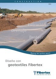
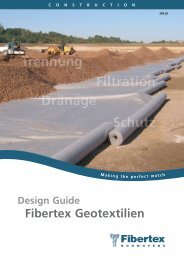
<strong>Fibertex</strong> <strong>Reinforcement</strong> products are cost effective<br />
and offer considerable performance benefits in<br />
sub-base layers and in the construction of steep<br />
slopes.<br />
<strong>Fibertex</strong> <strong>Reinforcement</strong>s are woven products made<br />
from various polymers including PP, PET and PVA<br />
(polypropylene, polyester, and polyvinyl alcohol).<br />
They are made from high tenacity yarns ensuring<br />
high strength and low elongation. For certain<br />
applications, <strong>Fibertex</strong> <strong>Reinforcement</strong>s are coated<br />
with PVC for maximum durability.<br />
Focus on the environment<br />
No chemical binders are used in <strong>Fibertex</strong> products<br />
or during the production process. Polypropylene<br />
is a polymer material and when incinerated it<br />
turns into carbon dioxide and water vapour, both<br />
completely harmless substances.<br />
Concern for the environment is proved by the<br />
fact that <strong>Fibertex</strong> is among the first in the<br />
nonwoven industry to introduce an environmental<br />
management system and thereby obtaining the<br />
ISO 14001 certificate. This ensures continuous<br />
focus on efficient and financially viable<br />
management of environmental issues, which in<br />
return ensures minimal harmful effects resulting<br />
from the company’s activities.<br />
Implemented at all levels in the organisation,<br />
daily focus is on waste handling/recycling,<br />
implementation of new technologies and<br />
minimisation of waste and energy consumption.<br />
The importance of quality<br />
<strong>Fibertex</strong>’s quality management system is certified<br />
in accordance with the most comprehensive<br />
standards set by the International Organisation<br />
for Standardisation namely DS/EN ISO 9001:2000.<br />
This means that the quality management system<br />
has been implemented and verified at all levels<br />
within the organisation.<br />
<strong>Fibertex</strong> <strong>Reinforcement</strong>s are CE marked under the<br />
EU Construction Products Directive. CE marking<br />
certifies that <strong>Fibertex</strong>’s quality management<br />
system (DS/EN ISO 9001:2000) complies with the<br />
EN standards (level 2+). <strong>Fibertex</strong> <strong>Reinforcement</strong>s<br />
are submitted to production control and tests in<br />
accordance with the EN standards.<br />
2
U C T I O N<br />
Applications<br />
with <strong>Fibertex</strong> <strong>Reinforcement</strong><br />
Steep reinforced slopes<br />
Reinforcing soils with high strength and low<br />
elongation geosynthetics enables soil structures<br />
to stay stable under high loads with vertical or<br />
near-vertical surfaces. The soils are added internal<br />
shear resistance through geosynthetics, and when<br />
wrapping the geosynthetics over the surface for<br />
each layer, the horizontal forces on the vertical<br />
surface are also absorbed in the geosynthetics.<br />
Asphalt reinforcement<br />
Reinforcing the lower part of the asphalt layer<br />
adds internal shear resistance to the asphalt.<br />
When the underlying surface contracts and<br />
expands with the temperature and when heavy<br />
loads are applied to the asphalt the reinforcement<br />
absorbs the tensile strains and thereby prevents<br />
the asphalt from cracking.<br />
Embankments<br />
Reinforcing the lower part of embankments<br />
prevents setting and sliding failures. The reinforcement<br />
distributes the vertical loads, and ensures<br />
horizontal stability by adding shear resistance at<br />
the base.<br />
3
C O N S T R<br />
Steep reinforced<br />
Slopes<br />
Steep reinforced slopes<br />
The design of a steep reinforced slope can be<br />
divided into five stages:<br />
1. Calculation of the total earth pressure<br />
2. Choice of reinforcement<br />
3. Determination of reinforcement spacing<br />
4. Determination of reinforcement length<br />
5. Calculation of wrapping length<br />
q [kN/m 2 ]<br />
1. Calculation of the total earth<br />
pressure<br />
The vertical pressure from the soil and a<br />
possible surcharge, r v , is used later to calculate<br />
the necessary anchoring length and is found as:<br />
r v,z = q + c • z<br />
Where,<br />
r v,z<br />
the vertical earth pressure at depth z in<br />
the slope [kN/m 2 ]<br />
q the surcharge load [kN/m 2 ]<br />
c the unit weight of the fill material [kN/<br />
m 3 ]<br />
z the vertical distance from the top of the<br />
slope [m]<br />
z [m]<br />
q [kN/m 2 ]<br />
q<br />
r v<br />
r h<br />
K • q<br />
h [m]<br />
Failure plane<br />
h [m]<br />
z [m]<br />
Reinforced<br />
slope<br />
Fill material:<br />
c [kN/m 3 ], u [°]<br />
Fig 15. Reinforced slope<br />
Fig 16. Total earth pressure<br />
q + c • h<br />
K • c • h + K • q<br />
4
U C T I O N<br />
K<br />
K<br />
K<br />
r u= 0.0<br />
0.5<br />
0.4<br />
0.3<br />
0.2<br />
0.1<br />
0<br />
30 40 50 60 70 80 90<br />
Slope angle b<br />
r u= 0.25<br />
0.7<br />
0.6<br />
0.5<br />
0.4<br />
0.3<br />
0.2<br />
0.1<br />
Figure: 4 Lateral earth pressure coefficient<br />
at different pore water pressure r u [Jewel<br />
1991]<br />
20°<br />
25°<br />
30°<br />
35°<br />
The total lateral (horizontal)<br />
earth pressure can be calculated<br />
as a percentage of the total<br />
vertical earth pressure. This<br />
percentage is called the lateral<br />
earth pressure coefficient, K:<br />
40°<br />
r h,z = K • c • z + K • q<br />
r u = H water • c water<br />
45°<br />
H • c soil<br />
Soil<br />
50°<br />
20°<br />
25°<br />
30°<br />
35°<br />
40°<br />
45°<br />
50°<br />
0<br />
30 40 50 60 70 80 90<br />
Slope angle b<br />
r u= 0.5<br />
0.8<br />
20°<br />
0.7<br />
25°<br />
30°<br />
35°<br />
0.6<br />
40°<br />
45°<br />
50°<br />
0.5<br />
0.4<br />
0.3<br />
0.2<br />
0.1<br />
0<br />
30 40 50 60 70 80 90<br />
Slope angle b<br />
Where,<br />
r h,z<br />
pressure<br />
Surcharge<br />
load<br />
the lateral earth pressure<br />
at depth z in the slope<br />
[kN/m 2 ]<br />
the lateral earth pressure<br />
coefficient [can be read<br />
from figure 4]<br />
c the unit weight of the<br />
fill material [kN/m 3 ]<br />
z the vertical distance<br />
from the top of the<br />
slope [m]<br />
q the surcharge load<br />
[kN/m 2 ]<br />
u the angle of internal<br />
friction in the fill<br />
material [º]<br />
slope angle [º]<br />
Pore Water Pressure<br />
r u =<br />
H water • c water<br />
H • c soil<br />
Where,<br />
r u Pore water pressure[-]<br />
H water Height of water table<br />
from base of the<br />
slope[m]<br />
{<br />
{<br />
H<br />
c w<br />
c soil<br />
H<br />
2. Choice of<br />
reinforcement<br />
Based on the calculations, a<br />
<strong>Fibertex</strong> reinforcement product<br />
is chosen, and the design long<br />
term tensile strength of the<br />
product, T lt , is calculated:<br />
T lt =<br />
Height of the slope[m]<br />
the unit weight of the<br />
water [kN/m 3 ]<br />
the unit weight of the<br />
soil [kN/m 3 ]<br />
c,u<br />
b<br />
Figure: 3 Pore water pressure<br />
T k<br />
H water<br />
f c • k i • k d • f m<br />
Where,<br />
T lt the long term tensile<br />
strength of a reinforcement<br />
product [kN/m]<br />
T k the short term tensile<br />
strength of a product<br />
(see datasheet) [kN/m]<br />
f c the creep reduction<br />
coefficient<br />
(see datasheet)<br />
k i the installation damage<br />
coefficient<br />
(see datasheet)<br />
k d the chemical<br />
degradation coefficient<br />
(see datasheet)<br />
f m the partial material<br />
coefficient (normally<br />
set to 1.4 for material<br />
security)<br />
5
C O N S T R<br />
Steep reinforced<br />
Slopes<br />
3. <strong>Reinforcement</strong> Spacing<br />
As the strength of the reinforcement in the<br />
face of the slope must always exceed the lateral<br />
earth pressure the reinforcement spacing, Sv, is<br />
calculated as:<br />
r h,z ≤ T lt<br />
S v<br />
S v ≤<br />
Lateral earth<br />
Pressure<br />
T lt<br />
r h,z<br />
<strong>Reinforcement</strong> strength<br />
per unit spacing<br />
Where,<br />
S v spacing of the reinforcement [m]<br />
T lt the long term tensile strength of a<br />
reinforcement product [kN/m]<br />
r h,z the lateral earth pressure at depth z in<br />
the slope [kN/m 2 ]<br />
As the stresses increase with the depth we have<br />
three possible approaches for designing the reinforcement<br />
spacing<br />
• Vary the spacing distance with same reinforcement<br />
strength<br />
• Vary the strength of the reinforcement with<br />
same spacing distance<br />
• Vary both the spacing distance and the strength<br />
of the reinforcement<br />
It is recommended to use only one or at most<br />
two types of reinforcement and vary the spacing<br />
distance.<br />
In theory the spacing distance, should be calculated<br />
for each new layer to minimize product<br />
consumption. However, in practice it is extremely<br />
work intensive and time consuming, so normally<br />
calculation of the spacing distance is done in 4-5<br />
intervals through out the entire construction.<br />
Because of the face stability problems and uneven<br />
characteristics of soil the vertical spacing should<br />
never exceed 1 m. If the stresses at the top are<br />
very low, the equation will compute a higher<br />
spacing which must then be regulated to 1 m.<br />
4. <strong>Reinforcement</strong> Length<br />
The reinforcement length is determined by one<br />
of two different situations. The length needed for<br />
internal stability and the length needed for external<br />
stability. The greater of two reinforcement<br />
lengths will be the design anchoring length.<br />
Internal stability<br />
There are two internal failure possibilities<br />
1. Internal direct sliding over reinforcement layer<br />
2. Pullout of reinforcement<br />
Internal direct sliding<br />
The direct sliding on top of the reinforcement is<br />
resisted by the friction developed at the interface<br />
between the soil and top of the reinforcement.<br />
The resistant shear stress provided by friction is<br />
given by:<br />
s ds = r v,z • f ds • tan()<br />
Where,<br />
s ds Shear stress required to resist direct sliding<br />
[kN/m 2 ]<br />
r v,z The vertical earth pressure at depth z in<br />
the slope [kN/m 2 ]<br />
f ds Factor of direct sliding (see table 1 for<br />
<strong>Fibertex</strong> reinforcement) [-]<br />
The angle of internal friction in the fill<br />
material [º]<br />
ds<br />
L A<br />
r n<br />
Figure: 5.1 Internal failure mode (direct sliding)<br />
L <br />
Direct Sliding over a reinforcement layer<br />
r h<br />
r h<br />
6<br />
L A<br />
L <br />
b
U C T I O N<br />
Required length of the reinforcement after failure<br />
plane for resisting direct sliding over reinforcement<br />
T lt<br />
L ,sliding =<br />
B • s ds<br />
Where,<br />
L ,sliding Required length of the reinforcement after<br />
failure plane to resist direct sliding [m]<br />
T lt the long term tensile strength of a<br />
reinforcement product [kN/m] (Found in<br />
section 2)<br />
B Width of the reinforcement in the<br />
anchorage zone [m]<br />
s ds Shear stress required to resist direct<br />
sliding [kN/m 2 ]<br />
f ds<br />
0.95-<br />
1.00<br />
Gravel Sand Silt Clay<br />
0.92-<br />
0.98<br />
0.80-<br />
0.90<br />
0.70-<br />
0.80<br />
Table 1. Recommended factor of direct sliding for various fill<br />
materials<br />
Pullout<br />
Pull out of the reinforcement is resisted by the<br />
friction provided by the soil above and below<br />
the reinforcement. The resistant shear stress is<br />
calculated as:<br />
s p = r v,z • fpo • tan()<br />
ds<br />
Where,<br />
s p Shear stress required to resist pullout [kN/m 2 ]<br />
L<br />
r v,z the vertical earth pressure A<br />
L<br />
at depth<br />
<br />
z in<br />
the slope [kN/m 2 ]<br />
fpo Factor Direct of pullout Sliding over (see a reinforcement table 2 for layer<br />
<strong>Fibertex</strong> reinforcement)<br />
the angle of internal friction in the fill<br />
material [º]<br />
r n<br />
r h<br />
Required length of the reinforcement after failure<br />
plane for resisting pullout of the reinforcement<br />
T lt<br />
L ,pullout =<br />
2 • B • s p<br />
Where,<br />
L ,pullout Required length of the reinforcement after<br />
failure plane to resist pullout [m]<br />
T lt the long term tensile strength of a<br />
reinforcement product [kN/m]<br />
(Found in section 2)<br />
B Width of the reinforcement in the<br />
anchorage zone [m]<br />
s p Shear stress required to resist pullout<br />
[kN/m 2 ]<br />
f po<br />
0.90-<br />
1.05<br />
Gravel Sand Silt Clay<br />
0.75-<br />
0.95<br />
0.70-<br />
0.90<br />
0.60-<br />
0.85<br />
Table 2. Recommended factor of pullout for various fill materials<br />
Required length of the reinforcement after failure<br />
plane for internal stability is given by:<br />
L = max (L ,sliding , L ,pullout )<br />
z [m]<br />
L A<br />
L rz<br />
b [°]<br />
45° + q/2<br />
Fill material:<br />
c kN/m 3 ] , u [°]<br />
L <br />
q [kN/m 2 ]<br />
S vz<br />
L A<br />
r h<br />
b<br />
L<br />
Figure: 6 <strong>Reinforcement</strong> spacing and length<br />
L <br />
Figure: 5.2 Internal failure <strong>Reinforcement</strong> mode (pullout) Pullout<br />
7
C O N S T R<br />
Steep reinforced<br />
Slopes<br />
<br />
Length of the reinforcement required for the<br />
internal stability<br />
L int ernal<br />
= L ε<br />
+ L A<br />
Where,<br />
L internal Total <strong>Reinforcement</strong> length for internal<br />
stability [m]<br />
L <strong>Reinforcement</strong> length after failure plane [m]<br />
L A <strong>Reinforcement</strong> length before the failure<br />
plane [m]<br />
⎡ ⎛<br />
L A<br />
= tan 45 − ρ ⎞<br />
⎤<br />
⎢ ⎜ ⎟ − tan(90 − β) ⎥ ∗H<br />
⎣ ⎝ 2⎠<br />
⎦<br />
<br />
angle of friction for design<br />
The total reinforcement length required for external<br />
stability is calculated as:<br />
L external = max [ H* • (L/H) ds , H* • (L/H) ovrl ]<br />
Where,<br />
L external Length of the reinforcement for external<br />
stability [m]<br />
H* Equivalent height [m]<br />
(L/H) ds Ratio of length and height required to<br />
prevent external direct sliding [can be<br />
read from figure 7]<br />
(L/H) ovrl Ratio of length and height required for<br />
overall stability of slope [can be read from<br />
figure 7]<br />
Length of the reinforcement required<br />
8<br />
<br />
<br />
⎛<br />
ρ = tan −1<br />
⎜<br />
⎝<br />
tan(ϕ)<br />
f m<br />
⎞<br />
⎟<br />
⎠<br />
the angle of internal friction in the fill<br />
material [º]<br />
ƒ m the partial material coefficient (normally<br />
set to1.4 for material security)<br />
Slope angle [º]<br />
H Height of the slope[m]<br />
External Stability<br />
For calculation of external stability the surcharge<br />
load if any is converted to an equivalent soil height<br />
and added to the actual height of the slope<br />
H* = H + q <br />
Where,<br />
H* Equivalent height[m]<br />
H Height of the slope[m]<br />
q The surcharge load [kN/m 2 ]<br />
c the unit weight of the fill material [kN/m 3 ]<br />
Knowing the pore water pressure and the slope<br />
angle, the length to height ratio can be read from<br />
the figure (7) for overall stability and direct sliding.<br />
L external = max ( L internal , L external )<br />
Where,<br />
L Length of the reinforcement [m]<br />
L internal Total <strong>Reinforcement</strong> length for internal<br />
stability [m]<br />
L external Length of the reinforcement for external<br />
stability [m]<br />
5. Wrapping Length<br />
Wrapping length at any depth z in the slope can<br />
be calculated by<br />
L rz =<br />
FS warp • K • (z + S v /2) • S v<br />
z c • f ds • tan()<br />
Where,<br />
L rz Wrapping length at depth z in the slope[m]<br />
FS 1.2-1.4 for <strong>Fibertex</strong> <strong>Reinforcement</strong><br />
ƒ ds Factor of direct sliding (see table 1 for<br />
<strong>Fibertex</strong> reinforcement)<br />
K the lateral earth pressure coefficient<br />
the angle of internal friction in the fill<br />
material [º]<br />
z the vertical distance from the top of the<br />
slope [m]<br />
S v Spacing of the reinforcement at depth z in<br />
the slope[m]
U C T I O N<br />
Overall Stability<br />
Length to height Length ratio to height ratio Length to height Length ratio to height ratio<br />
Length Overall to height stability ratio Overall stability External direct Length External sliding to height direct ratio sliding<br />
ru= 0.00 ru= 0.00<br />
ru= 0.00 ru= 0.00<br />
(L/H)ovri<br />
(L/H)ovri<br />
(L/H)ovri<br />
1.2<br />
1<br />
1<br />
1.4<br />
1.2<br />
1.4<br />
1.2<br />
0.8<br />
0.6<br />
0.8<br />
0.6<br />
20°<br />
25°<br />
30°<br />
35°<br />
1<br />
0.8<br />
20°<br />
25°<br />
30°<br />
35°<br />
1<br />
0.8<br />
40°<br />
0.6<br />
40°<br />
0.6<br />
20°<br />
20°<br />
0.4<br />
0.4<br />
45°<br />
45°<br />
50°<br />
50°<br />
0.4<br />
0.4<br />
25°<br />
25°<br />
0.2<br />
0.2<br />
0.2<br />
0.2<br />
30°<br />
30°<br />
35°<br />
35°<br />
40°<br />
40°<br />
0<br />
0<br />
0<br />
0<br />
45°<br />
45°<br />
30 40 50 60 3070 4080 5090<br />
60 70 30 80 40 90 50 60 3070 4080 5090<br />
60 70 80 90<br />
Slope angle <br />
Slope angle <br />
Slope angle <br />
Slope angle <br />
ru= 0.25<br />
2<br />
2<br />
1.8<br />
1.6<br />
1.4<br />
1.2<br />
1.8<br />
1.6<br />
1.4<br />
1.2<br />
1.8<br />
1.6<br />
1.4<br />
1.2<br />
1.8<br />
1.6<br />
1.4<br />
1.2<br />
1<br />
1<br />
1<br />
20°<br />
20°<br />
1<br />
20°<br />
20°<br />
0.8<br />
0.8<br />
25° 0.8<br />
25°<br />
30°<br />
30°<br />
0.8<br />
0.6<br />
0.6<br />
35°<br />
40° 0.6<br />
35°<br />
40° 0.6<br />
25°<br />
25°<br />
0.4<br />
0.4<br />
45°<br />
50° 0.4<br />
45°<br />
50° 0.4<br />
30°<br />
35°<br />
30°<br />
35°<br />
0.2<br />
0<br />
0.2<br />
0<br />
0.2<br />
0<br />
0.2<br />
0<br />
40°<br />
45°<br />
50°<br />
40°<br />
45°<br />
50°<br />
30 40 50 60 3070 4080 5090<br />
60 70 30 80 40 90 50 60 3070 4080 5090<br />
60 70 80 90<br />
Slope angle <br />
Slope angle <br />
Slope angle <br />
Slope angle <br />
ru= 0.5<br />
2.8<br />
2.6<br />
(L/H)ovri<br />
(L/H)ovri<br />
ru= 0.25<br />
2<br />
2.8<br />
2.6<br />
(L/H)ds<br />
(L/H)ds<br />
3.5<br />
2.4<br />
2.4<br />
3<br />
3<br />
2.2<br />
2.2<br />
2<br />
1.8<br />
2<br />
1.8<br />
2.5<br />
2.5<br />
1.6<br />
1.6<br />
20° 2<br />
20° 2<br />
20°<br />
20°<br />
1.4<br />
1.4<br />
1.2<br />
1.2<br />
25° 1.5<br />
25° 1.5<br />
1<br />
1<br />
30°<br />
30°<br />
25°<br />
25°<br />
30°<br />
30°<br />
0.6<br />
0.6<br />
45°<br />
45°<br />
50°<br />
50°<br />
35°<br />
35°<br />
0.4<br />
0.4<br />
0.5<br />
0.5<br />
40°<br />
40°<br />
0.8<br />
0.8<br />
35°<br />
40° 1<br />
35°<br />
40° 1<br />
0.2<br />
0.2<br />
45°<br />
45°<br />
50°<br />
50°<br />
0<br />
0<br />
0<br />
0<br />
30 40 50 60 3070 4080 5090<br />
60 70 30 80 40 90 50 60 3070 4080 5090<br />
60 70 80 90<br />
Slope angle Slope angle <br />
Slope angle <br />
Slope angle <br />
(L/H)ovri<br />
1.2<br />
ru= 0.5<br />
(L/H)ds<br />
1.6<br />
ru= 0.25<br />
ru= 0.5<br />
External direct sliding<br />
Figure: 7 The Relation between the length of reinforcement and the slope height for the overall stability and<br />
external direct sliding at different pore water pressure [Jewel 1991]<br />
(L/H)ds<br />
(L/H)ds<br />
(L/H)ds<br />
1.6<br />
ru= 0.25<br />
2<br />
ru= 0.5<br />
3.5<br />
9
C O N S T R<br />
Asphalt<br />
<strong>Reinforcement</strong><br />
Asphalt reinforcement<br />
The design of reinforced asphalt pavements can<br />
be divided in to three parts:<br />
1. Design of asphalt layer<br />
a. Design of layer thickness<br />
2. Design of foundation layer<br />
a. Calculation of equivalent wheel load<br />
b. Calculation of the pressure on<br />
the fill layer<br />
c. Determination of the fill layer depth<br />
d. Choice of reinforcement<br />
3. Design checks<br />
a. Check for the stability of fill<br />
b. Check for the stability of subsoil<br />
400<br />
300<br />
Asphalt<br />
thickness<br />
(mm) 200<br />
1. Design of asphalt layer<br />
Asphalt reinforcement is used to prevent classical<br />
fatigue cracking of new asphalt or reflection<br />
cracking in asphalt repairs. The presence of the<br />
grid will inhibit cracking under repeated loading<br />
through control of local tensile strains and will<br />
therefore result in a lower required thickness of<br />
the layer.<br />
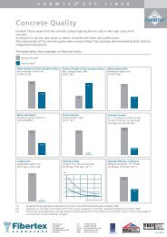
a. Thickness of asphalt layer<br />
The thickness of the asphalt layer can be read<br />
from the graph in Figure 1 when having decided<br />
the design life in terms of millions of standard<br />
axles.<br />
Dense bitumen<br />
macadam.<br />
unreinforced<br />
grid reinforced<br />
(bottom)<br />
100<br />
1.0 10<br />
100<br />
Design life (msa)<br />
Figure: 1 Asphalt layer thickness design<br />
10
U C T I O N<br />
2. Design of foundation layer<br />
Foundation of a paved road can be designed as<br />
an unpaved road with small allowable rut depth.<br />
c. Determination of the fill layer depth<br />
The required depth of the fill layer can be found<br />
from one of charts shown in the Figure 3. To<br />
select the correct chart, the variable<br />
<br />
<br />
a. Calculation of equivalent wheel load<br />
Using the number of passes for the life of the<br />
paved structure, the equivalent wheel load is derived<br />
from the equation<br />
F e<br />
= F p ( N p ) .16<br />
Where,<br />
F e Equivalent wheel load [kN]<br />
F p Maximum single wheel load [kN]<br />
N p Number of traffic passes [-]<br />
b. Calculation of the pressure on the fill layer<br />
The pressure on the fill layer is given by:<br />
P f<br />
=<br />
F e<br />
2<br />
π ∗R af<br />
Due to wheel<br />
load<br />
+ γ a<br />
∗D a<br />
Due to asphalt<br />
layer<br />
Where,<br />
P f Pressure on the fill layer [kN/m 2 ]<br />
F e Equivalent wheel load [kN] (calculated in<br />
section 2.a)<br />
R af Radius of distributed load between asphalt<br />
layer and fill layer [m]<br />
R af<br />
= R + D a<br />
∗ tanβ a<br />
C u / f R af ) must be calculated<br />
Where,<br />
C u Undrained shear strength of subsoil<br />
[kN/m 2 ]<br />
f Unit weight of the fill material [kN/m 3 ]<br />
R af Radius of distributed load between<br />
asphalt layer and fill layer [m] (calculated<br />
in section 2.b)<br />
The value of D f /R af is then read from the graph<br />
using the variables P f /C f and f<br />
Where,<br />
D f Depth of the fill layer [m]<br />
R af Radius of distributed load between<br />
asphalt layer and fill layer [m] (calculated<br />
in section 2.b)<br />
P f Pressure on the fill material [kN/m 2 ]<br />
(calculated in section 2b)<br />
f Load spreading angle of the fill layer [º]<br />
(For a good compacted fill material<br />
f = 35º)<br />
If a chart for the particular value of C u / f R af )<br />
is not available interpolation between the two<br />
nearest read values can be applied<br />
<br />
R<br />
Radius of circular contact area between tire<br />
and road surface [m]<br />
F p<br />
R<br />
<br />
R =<br />
F p<br />
F p<br />
π ∗P t<br />
Average single wheel load [kN]<br />
(found in section 2.a)<br />
P t Wheel pressure [kN/m 2 ]<br />
D a<br />
Depth of asphalt layer [m] (calculated in<br />
previous section)<br />
a Load spreading angle of the asphalt layer [º]<br />
(For a good compacted asphalt layer a = 40º)<br />
a Unit weight of asphalt layer [kN/m 3 ]<br />
Asphalt<br />
geogrid<br />
Granulat fill<br />
geogrid<br />
Subsoil<br />
a<br />
f<br />
f<br />
Figure: 2 Forces on the pavement<br />
<br />
R af<br />
R fs<br />
P f<br />
P r<br />
P xx<br />
P u<br />
Da<br />
Dr<br />
FS rw<br />
FS soil<br />
11
C O N S T R<br />
Asphalt<br />
<strong>Reinforcement</strong><br />
<br />
When D f /R af is read the depth of the fill can be<br />
calculated from<br />
⎛<br />
D f<br />
= R af<br />
∗⎜<br />
⎝<br />
D f<br />
R af<br />
⎞<br />
⎟<br />
⎠<br />
Where,<br />
D f Depth of the fill layer [m]<br />
R af Radius of distributed load between<br />
asphalt layer and fill layer [m] (calculated<br />
in section 2.b)<br />
Pf/Cu<br />
Pf/Cu<br />
30<br />
25<br />
20<br />
15<br />
10<br />
5<br />
25<br />
20<br />
15<br />
10<br />
f = 45 f = 35 f = 25<br />
0<br />
0 0.5 1 1.5 2 2.5 3 3.5<br />
Design chart for (C u/ f*R af = 5)<br />
f = 45 f = 35 f = 25<br />
30<br />
d. Choice of reinforcement<br />
The required strength of the asphalt reinforcement<br />
can be found from one of the charts shown in<br />
Figure 4. To select the correct chart, the variable<br />
must be calculated (as in section 2.c).<br />
C u / f R af )<br />
Where,<br />
C u Undrained shear strength of subsoil<br />
[kN/m 2 ]<br />
f Unit weight of fill material [kN/m 3 ]<br />
R af Radius of distributed load between<br />
asphalt layer and fill layer [m] (calculated<br />
in section 2.b)<br />
The value of D f /R af is then read from the graph<br />
using the variables P f /Cu, f and f<br />
Where,<br />
D f Depth of the fill layer[m]<br />
R af Radius of distributed load between<br />
asphalt layer and fill layer [m] (calculated<br />
in section 2.b)<br />
P f Pressure on the fill material [kN/m 2 ]<br />
(calculated in section 2b)<br />
C u Undrained shear strength of subsoil [kN/m 2 ]<br />
f Load spreading angle of the fill layer [º]<br />
f angle of friction in the fill material [º]<br />
5<br />
0<br />
0 0.5 1 1.5 2 2.5<br />
Design chart for (C u/ f*R af = 10)<br />
3 3.5<br />
If a chart for the particular value of C u / f R af )<br />
is not available interpolation between the two<br />
nearest read values can be applied.<br />
12<br />
Pf/Cu<br />
30<br />
25<br />
20<br />
15<br />
10<br />
5<br />
f = 45 f = 35 f = 25<br />
0<br />
0 0.5 1 1.5 2 2.5 3 3.5<br />
Design chart for (C u/ f*R af = 20)<br />
Figure: 3 Chart for designing the depth of the fill layer<br />
When T req /C u R af ) is found the required tensile<br />
strength of the reinforcement can be calculated<br />
from<br />
T<br />
T req = R af • C u •<br />
(<br />
req<br />
R af<br />
)<br />
• C u<br />
Where,<br />
T req Required tensile strength of the<br />
reinforcement [kN/m]<br />
R af Radius of distributed load between asphalt<br />
layer and fill layer [m] (calculated in section<br />
2.b)<br />
C u Undrained shear strength of subsoil [kN/m 2 ]
U C T I O N<br />
Required Force T req /CuR af<br />
Required Force T req /CuR af<br />
Required Force T req /CuR af<br />
C u<br />
Design chart for = 5 and ß = 25°<br />
R f R af<br />
C u<br />
Design chart for = 5 and ß = 35°<br />
R f R af<br />
f = 50° 45° f = 50° 45°<br />
f =<br />
50° 45°<br />
1<br />
1<br />
1<br />
1<br />
1<br />
1<br />
1<br />
1<br />
1<br />
1<br />
30°<br />
1<br />
1 2 3 4<br />
Dept<br />
Design chart for<br />
5<br />
of Fill<br />
C u<br />
C u<br />
40°<br />
35°<br />
6 7 8 9<br />
DIR af<br />
= 20 and ß = 25°<br />
1<br />
1<br />
1<br />
1<br />
1<br />
1<br />
40°<br />
1<br />
1<br />
1<br />
1<br />
1<br />
1<br />
1<br />
1<br />
1<br />
1<br />
1<br />
1<br />
1<br />
1<br />
30° 35°<br />
1 1 1 2 3 4 5 6 7 8 9<br />
1 2 3 4<br />
Dept of Fill DIR af<br />
Dept<br />
C u<br />
C u<br />
Design chart for = 20 and ß = 35° Design chart for<br />
R f R af<br />
30°<br />
5<br />
of Fill<br />
C u<br />
C u<br />
40°<br />
35°<br />
6 7 8 9<br />
DIR af<br />
= 20 and ß = 45°<br />
R f R af<br />
Design chart for = 10 and ß = 25° Design chart for = 10 and ß = 35°<br />
R f R af<br />
Design chart for = 10 and ß = 45°<br />
R f R af<br />
f = 50° 45° 40° f = 50° 45° 40° f =<br />
50° 45° 40°<br />
1<br />
1<br />
1<br />
1<br />
1<br />
1<br />
35°<br />
1<br />
1<br />
1<br />
1<br />
1<br />
1<br />
35°<br />
1<br />
1<br />
1<br />
35°<br />
1<br />
1<br />
1<br />
1<br />
1<br />
1<br />
1<br />
1<br />
1<br />
1<br />
1<br />
1<br />
1<br />
1<br />
1<br />
30°<br />
30°<br />
30°<br />
1<br />
1 1<br />
1 2 3 4 5 6 7 8 9<br />
1 2 3 4 5 6 7 8 9<br />
1 2 3 4 5 6 7 8 9<br />
Dept of Fill DIR af<br />
Dept of Fill DIR af<br />
Dept of Fill DIR af<br />
R f R af<br />
1<br />
Design chart for = 5 and ß = 45°<br />
R f R af<br />
f = 50° 45° 40° f = 50°45° 40° 35° f = 50°45° 40° 35°<br />
1<br />
1<br />
1<br />
35° 1<br />
1<br />
1<br />
1<br />
1<br />
30°<br />
1<br />
1<br />
1<br />
1<br />
1<br />
1<br />
1<br />
30° 1<br />
30°<br />
1<br />
1<br />
1<br />
1<br />
1<br />
1<br />
1<br />
1<br />
1<br />
1<br />
1<br />
1<br />
1<br />
1<br />
1 2 3 4 5 6 7 8 9<br />
1 1 2 3 4 5 6 7 8 9<br />
1 1 2 3 4 5 6 7 8 9<br />
Dept of Fill DIR af<br />
Dept of Fill DIR af<br />
Dept of Fill DIR af<br />
C u<br />
R f R af<br />
Figure: 4 Charts for tensile force in reinforcement<br />
13
C O N S T R<br />
Asphalt<br />
<strong>Reinforcement</strong><br />
<br />
3. Design Checks<br />
a. Stability of fill<br />
The stability of the fill can be checked by calculating<br />
the factor of safety for bearing failure.<br />
The factor of safety is calculated as the bearing<br />
capacity of the fill divided by the actual pressure<br />
applied to the fill (calculated in section 2b.)<br />
<br />
The Bearing Capacity of the fill is found as:<br />
P y = 0.6 • R af • f • N <br />
Where,<br />
P y Bearing capacity of fill layer [kN/m 2 ]<br />
R af Radius of distributed load between<br />
asphalt layer and fill layer [m] (calculated<br />
in section 2.b)<br />
f Unit weight of the fill material [kN/m 3 ]<br />
N Bearing capacity factor for a rough<br />
base footing [-]<br />
N = 2 • R af • (N q + 1) • (tan) ƒ<br />
N q Bearing capacity factor for the fill<br />
material [-]<br />
f<br />
N q<br />
= 1+ sinϕ f<br />
1− sinϕ f<br />
∗e π∗tan ϕ f<br />
Internal angle of friction of the fill material<br />
[º]<br />
<br />
0.6 is the shape factor for an axial symmetry.<br />
FS fill<br />
= P y<br />
P f<br />
Where,<br />
FS fill Factor of safety for the stability of fill [-]<br />
(Normally greater then 1.2 for material<br />
security)<br />
P y Bearing capacity of the fill layer [kN/m 2 ]<br />
P f Pressure on the fill layer [kN/m2] (calculated<br />
in section 2b)<br />
If the desired factor of safety is reached, the fill<br />
will be able to bear the proposed pavement.<br />
Otherwise either,<br />
• increase the load spreading angle in the<br />
asphalt layer by,<br />
º increasing the thickness of the asphalt<br />
layer or<br />
º using a different type of asphalt<br />
or,<br />
• increase the angle of friction in the fill layer<br />
by,<br />
º increasing compaction<br />
º using a different fill material<br />
b. Stability of subsoil<br />
The stability of the subsoil can be checked by<br />
calculating the factor of safety for bearing failure.<br />
The factor of safety is calculated as the bearing<br />
capacity of the subsoil divided by the applied<br />
pressure on the subsoil<br />
The bearing capacity of the subsoil is found as:<br />
⎛<br />
P u<br />
= N c<br />
∗C u<br />
∗ R ⎞<br />
fs<br />
⎜ ⎟<br />
⎝ ⎠<br />
R af<br />
Where,<br />
P u Bearing capacity of the sub soil [kN/m 2 ]<br />
N u Bearing capacity factor for the subsoil [-]<br />
(5.69 for reinforced structures)<br />
C u Undrained shear strength of the subsoil<br />
[kN/m 2 ]<br />
R fs Radius of distributed load between fill<br />
material and subsoil [m]<br />
R fs = R af + D f • f • tan f<br />
R af Radius of distributed load between<br />
asphalt layer and fill layer [m] (calculated<br />
in section 2.b)<br />
D f Thickness of the fill layer [m]<br />
f Load spreading angle of the fill layer [º]<br />
14
U C T I O N<br />
<br />
The pressure on the subsoil P es is found as:<br />
P es<br />
=<br />
F e<br />
π ∗R + γ ∗D + γ ∗D 2 a a f f<br />
fs<br />
Where,<br />
P es pressure on the subsoil [kN/m 2 ]<br />
F e Equivalent wheel load [kN] (calculated in<br />
section 2a)<br />
R fs Radius of distributed load between fill<br />
material and subsoil [m]<br />
R fs = R af + D f • f • tan f<br />
R af Radius of distributed load between<br />
asphalt layer and fill layer [m] (calculated<br />
in section 2.b)<br />
D f Thickness of the fill layer [m]<br />
f Load spreading angle of the fill layer [º]<br />
a Unit weight of asphalt layer [kN/m 3 ]<br />
D a Thickness of asphalt layer [m]<br />
f Unit weight of fill material [kN/m 3 ]<br />
If the desired factor of safety is reached, the<br />
subsoil is mechanically stable.<br />
Otherwise either,<br />
• increase the load spreading angle by,<br />
º increasing the thickness of the fill<br />
material, or by<br />
º increasing the compaction of the fill<br />
material, or by<br />
º using a different fill material<br />
or,<br />
• increase the Cu value of the subsoil by<br />
artificial consolidation.<br />
<br />
The factor of safety can then be calculated as:<br />
FS soil<br />
= P u<br />
P es<br />
Where,<br />
FS soil Factor of safety for the stability of the<br />
subsoil [-]<br />
P es Equivalent pressure on the subsoil [kN/m 2 ]<br />
P u Bearing capacity of the subsoil [kN/m 2 ]<br />
15
C O N S T R<br />
Design of<br />
Embankment<br />
Design of Embankment<br />
The design of an embankment can be divided<br />
into two stages, check for the bearing capacity of<br />
the foundation soil and if the bearing capacity is<br />
sufficient then design of the embankment.<br />
1. Checking the bearing capacity of<br />
foundation soil<br />
a. Calculation of equivalent footing width<br />
b.Calculation of bearing capacity of<br />
foundation soil<br />
c. Calculation of applied stresses<br />
d. Calculation of the factor of safety for<br />
bearing failure<br />
1. Checking the bearing capacity<br />
of foundation soil<br />
The equivalent footing width is used to calculate<br />
the bearing capacity of the foundation soil with<br />
the chosen embankment on top. After the bearing<br />
capacity of the chosen embankment is calculated<br />
the stresses that are actually applied are<br />
found and the two are compared to get a factor<br />
of safety.<br />
Embankment fill<br />
<strong>Reinforcement</strong><br />
2. Designing the Embankment<br />
a. Calculation of restoring and overturning<br />
moment<br />
b. Fixing the slip circle<br />
c. Calculation of required reinforcement<br />
strength<br />
Lateral Sliding<br />
Rotational Failure<br />
Figure: 1 Typical Failure mode for an embankment<br />
Lateral Extrusion of<br />
foundations (Bearing<br />
capacity failure)<br />
16<br />
Embankment<br />
n<br />
B<br />
b<br />
n(H - h*) nh*
U C T I O N<br />
a. Calculation of equivalent footing width<br />
Equivalent footing width is used for changing<br />
the non uniform vertical load distribution on the<br />
footing of embankment to uniform vertical load<br />
distribution for the calculation of bearing<br />
capacity.<br />
B = b + 2n(H − h ∗ )<br />
Where,<br />
q u Bearing Capacity [kN/m 2 ]<br />
N c Bearing capacity factor [-]<br />
C u Undrained shear strength of soil beneath<br />
the footing [kN/m 2 ]<br />
B Equivalent footing width of<br />
Embankment [m]<br />
D Depth of the soft soil [m]<br />
<br />
<br />
Where,<br />
h ∗ = C u<br />
(2 + π)<br />
γ<br />
B Equivalent footing width of embankment<br />
[m]<br />
b Embankment crest width [m]<br />
n Cotangent of the slope angle [-]<br />
H Height of Embankment [m]<br />
C u Undrained shear strength of soil beneath <br />
the footing [kN/m 2 ]<br />
Embankment fill unit weight [kN/m 3 ]<br />
c. Calculation of applied Bearing Stress<br />
The vertical pressure applied by the fill material<br />
on the foundation soil is found by:<br />
[ ( )]<br />
q a<br />
= γ b ∗H + n H2 − (h ∗ ) 2<br />
Where,<br />
h ∗ = C u<br />
(2 + π)<br />
γ<br />
q a Applied stress [kN/m 2 ]<br />
B<br />
b. Calculation of bearing capacity of foundation <br />
soil<br />
A bearing capacity factor is multiplied to the soil<br />
strength depending on the dimensions of the<br />
overlaying embankment<br />
q u<br />
= N c<br />
∗C u<br />
Embankment fill unit weight [kN/m 3 ]<br />
b<br />
H<br />
Embankment crest width [m]<br />
Height of Embankment [m]<br />
n Cotangent of the slope angle [-]<br />
B<br />
Equivalent footing width of<br />
embankment [m]<br />
<br />
<br />
<br />
for<br />
for<br />
B<br />
D < 2: N c = 2 + π<br />
Rotational Failure<br />
B<br />
D ≥ 2: N = π + .5 ⎛ B<br />
c ⎜<br />
⎝ D + 2 ⎞<br />
⎟<br />
⎠<br />
Embankment n<br />
Rigid footing<br />
D d<br />
Lateral Sliding<br />
Fill<br />
B<br />
b<br />
Unit weight<br />
<br />
Embankment fill<br />
<strong>Reinforcement</strong><br />
Lateral Extrusion of<br />
foundations (Bearing<br />
capacity failure)<br />
n(H - h*) nh*<br />
<br />
H<br />
h*<br />
Calculation of the factor of safety for bearing<br />
failure.<br />
FS b<br />
= q u<br />
q a<br />
Where,<br />
q a Applied bearing stress by the fill [kN/m 2 ]<br />
q u Bearing Capacity of foundation soil<br />
[kN/m 2 ]<br />
FS b Factor of safety for bearing capacity [-]<br />
Figure: 2 Embankment on soft soil<br />
(Xc, Zc) Circle centre<br />
Zc<br />
R<br />
h <br />
ZR<br />
W1<br />
(X )<br />
Zc<br />
W2<br />
(X2)<br />
Embankment<br />
fill h<br />
c, u<br />
17
C O N S T R<br />
Design of<br />
Embankment<br />
<br />
Recommended factor of safety for bearing<br />
capacity is 3.<br />
If the desired factor of safety is reached, the<br />
foundation soil will be able to bear the proposed<br />
embankment and calculation of the reinforcement<br />
can be done.<br />
<br />
If not, then either a lower factor of safety would<br />
have to be accepted or improvement of the<br />
foundation soil would be needed.<br />
2. Designing the Embankment<br />
The required tensile strength of the reinforcement<br />
for designing the embankment can be determined<br />
by considering the global stability analysis<br />
of desired embankment.<br />
FS g<br />
=<br />
Re storingMoments<br />
OverturningMoments<br />
a. Calculation of restoring and overturning<br />
moment<br />
The restoring moment (RM) is the mechanism<br />
that works against the failure. It is provided by<br />
the mobilized shear strength along the failure<br />
surface in the foundation soil and the tensile<br />
force in the reinforcement.<br />
The overturning moment (OM) is the mechanism<br />
that causes the failure it is an effect of the horizontal<br />
earth pressure from the embankment fill<br />
and the self weight of embankment fill applied to<br />
the foundation soil.<br />
RM = Z r<br />
∗ T g<br />
+ C u<br />
∗R 2 ∗θ<br />
Due to<br />
<strong>Reinforcement</strong><br />
Due to shear<br />
strength of foundation<br />
K a<br />
=<br />
1− sinϕ<br />
1+ sinϕ<br />
Where,<br />
RM Restoring Moments [kN-m]<br />
Z r Vertical distance of the reinforcement<br />
from the center of slip circle [m]<br />
T g Limiting tensile force developed in the<br />
reinforcement [kN/m]<br />
C u Undrained shear strength of soil beneath<br />
the footing [kN/m 2 ]<br />
R Radius of the slip circle [m]<br />
h Angle made by the slip circle to the center<br />
[º]<br />
OM Overturning Moments [kN-m]<br />
K a<br />
Embankment fill<br />
Coefficient of active earth pressure [-]<br />
c<br />
<strong>Reinforcement</strong><br />
Lateral Sliding<br />
Embankment fill unit weight [kN/m3]<br />
Rotational Failure<br />
H<br />
Lateral<br />
Height of Embankment [m] foundations<br />
Extrusion of<br />
(Bearing<br />
capacity failure)<br />
Z c Z coordinate of the slip circle center [m]<br />
W i Weight of the embankment fill in region i<br />
[kN]<br />
B<br />
n(H - h*) nh*<br />
m<br />
b<br />
number of regions [-]<br />
x i x coordinate of center of mass in region i<br />
Fill<br />
Unit weight<br />
H<br />
[-]<br />
<br />
h*<br />
x c X coordinate of the slip circle center [-]<br />
the angle of internal friction in the fill<br />
material [º]<br />
Embankment n<br />
Rigid footing<br />
D d<br />
Zc<br />
(0,0)<br />
R<br />
(Xc, Zc) Circle centre<br />
ZR<br />
h <br />
W1<br />
(X1)<br />
Zc<br />
<strong>Reinforcement</strong><br />
Interface shear<br />
W2<br />
(X2)<br />
Embankment<br />
fill h<br />
c, u<br />
T<br />
chKa<br />
<br />
OM = 1 2 ∗K ∗ γ ⎛<br />
a ∗H2 Z c<br />
− H ⎞<br />
⎜ ⎟<br />
⎝ 3⎠<br />
+<br />
m<br />
∑<br />
i=1<br />
W i<br />
( x i<br />
− x c )<br />
Soft clay<br />
foundation<br />
D<br />
<br />
Due to horizontal<br />
earth pressur<br />
Due to self weight<br />
of fill material<br />
Rigid base<br />
Figure: 2 Embankment on soft soil<br />
18
U C T I O N<br />
b. Fixing the slip circle<br />
This method can be easily implemented in the<br />
form of a computer program, which can search<br />
for a slip circle giving the lowest factor of safety<br />
of the desired embankment. Once the slip circle is<br />
fixed then all the values related to geometry (R, h,<br />
X and Z coordinates) are fixed.<br />
<br />
Recommended factor of safety for global stability<br />
is 1.5.<br />
2. Calculation for T p<br />
T p<br />
= 2<br />
x c +R sin( θ 2 )<br />
∫ σ n<br />
0<br />
dx<br />
Where,<br />
T p Pullout strength of reinforcement [kN/m]<br />
σ n Normal stress acting on the reinforcement<br />
[kN/m 2 ]<br />
σ n<br />
= γ ∗ z<br />
<br />
<br />
c. Calculation of required reinforcement strength<br />
The limiting force developed in the reinforcement<br />
( )<br />
T g<br />
= min T s<br />
,T p<br />
,T lt<br />
,T a<br />
Where,<br />
T s Required reinforcement strength to resist<br />
shear failure [kN/m]<br />
T p Required reinforcement strength to resist<br />
pullout [kN/m]<br />
T lt the long term tensile strength of a<br />
reinforcement product [kN/m]<br />
T a Required reinforcement strength required<br />
to maintain allowable strain [kN/m] <br />
1. Calculation for T s<br />
Sum of thrust force in fill and clay fill interface<br />
shear<br />
T s<br />
= 1 2 ∗K ∗ γ ⎡ ⎛<br />
a ∗H2 + δ ∗C u<br />
x c<br />
+ R ∗ sin θ ⎞ ⎤<br />
⎢ ⎜ ⎟ ⎥<br />
⎣ ⎝ 2⎠<br />
⎦<br />
Thrust force<br />
In fill<br />
Shear at<br />
clay fill interface<br />
Where,<br />
T s Required reinforcement strength to resist<br />
shear failure [kN/m]<br />
K a Coefficient of active earth pressure [-]<br />
Embankment fill unit weight [kN/m 3 ]<br />
coefficient of friction at clay fill interface [-]<br />
C u Undrained shear strength of soil beneath<br />
the footing [kN/m 2 ]<br />
<br />
x c X coordinate of the slip circle center [-]<br />
R Radius of the slip circle [m]<br />
h Angle made by the slip circle to the<br />
center [º]<br />
<br />
z<br />
the vertical distance from the surface of<br />
the slope [m]<br />
x c X coordinate of the slip circle center [-]<br />
R<br />
Radius of the slip circle [m]<br />
h Angle made by the slip circle to the center [º]<br />
3. Calculation for Tlt<br />
Allowable reinforcement force governed by strength,<br />
T k<br />
T lt<br />
=<br />
f c<br />
∗k i<br />
∗k d<br />
∗ f m<br />
Where,<br />
T lt the long term tensile strength of a<br />
reinforcement product [kN/m]<br />
T k the short term tensile strength of a<br />
product (see datasheet) [kN/m]<br />
f c the creep reduction coefficient (see datasheet)<br />
k i the installation damage coefficient<br />
(see datasheet)<br />
k d the chemical degradation coefficient<br />
(see datasheet)<br />
f m the partial material coefficient (normally set<br />
to 1.4 for material security)<br />
4. Calculation for T a<br />
Allowable reinforcement force governed by<br />
allowable strain a , T a<br />
T a<br />
= J∗ ε a<br />
Where,<br />
T a <strong>Reinforcement</strong> force governed by allowable<br />
strain [kN/m]<br />
J Secant stiffness of reinforcement over the range<br />
(0- a a) (Can be found from stress strain curve)<br />
a Allowable tensile strain in the reinforcement [-]<br />
19
C O N S T R U C T I O N<br />
Denmark<br />
Czech Republic<br />
Malaysia<br />
Facts about <strong>Fibertex</strong><br />
The <strong>Fibertex</strong> Group is a market leading manufacturer of needlepunch<br />
and spunmelt nonwovens. Headquartered in Aalborg, Denmark,<br />
with production in Denmark, Malaysia and the Czech Republic, <strong>Fibertex</strong><br />
is globally represented. Since its foundation in 1968, <strong>Fibertex</strong> has<br />
continuously expanded and today manufactures nonwovens for<br />
customers all over the world for many different applications.<br />
The <strong>Fibertex</strong> way<br />
The <strong>Fibertex</strong> supply chain ensures that we do our utmost to fulfil our<br />
customers demands. This process is an efficient management tool,<br />
it helps us to maintain our superior level of technical support, R&D,<br />
logistics, production and quality in all areas. We strive to provide an<br />
unparralled service to our customers from initial contact to delivery and<br />
after-sales service.<br />
Disclaimer<br />
The information given in this publication is of an illustrative nature.<br />
The manner of use is the sole responsibility of the user and the user<br />
must assume all risk and liability in connection herewith.<br />
B10 MARKETING A/S 031.550.GB/07.12<br />
<strong>Fibertex</strong> A/S<br />
Svendborgvej 2, Box 8029<br />
DK-9220 Aalborg Ø Denmark<br />
Tel. +45 96 35 35 35<br />
Fax +45 98 15 85 55<br />
fibertex@fibertex.com<br />
www.fibertex.com<br />
<strong>Fibertex</strong> A/S<br />
Box 8029<br />
Svendborgvej 2<br />
DK-9220 Aalborg Ø<br />
Denmark<br />
Contact us at:<br />
Tel. +45 96 35 35 35<br />
Fax +45 98 15 85 55<br />
E-mail fibertex@fibertex.com<br />
Web www.fibertex.com