TurboCAD Pro V15 - Construction Drawings - Textual Creations
TurboCAD Pro V15 - Construction Drawings - Textual Creations
TurboCAD Pro V15 - Construction Drawings - Textual Creations

You also want an ePaper? Increase the reach of your titles
YUMPU automatically turns print PDFs into web optimized ePapers that Google loves.
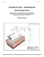
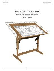
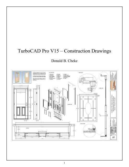
<strong>TurboCAD</strong> <strong>Pro</strong> <strong>V15</strong> – <strong>Construction</strong> <strong>Drawings</strong><br />
Donald B. Cheke<br />
1
Copyright © 2008 Donald B. Cheke<br />
<strong>TurboCAD</strong> is a registered trademark of<br />
IMSI Design.<br />
Published by:<br />
Donald B. Cheke<br />
Saskatoon, SK Canada<br />
Visit: www.textualcreations.ca<br />
All rights reserved<br />
No part of this document may be reproduced, copied, stored on a retrieval system or transmitted in any<br />
form without written permission from the author. The purchaser may, however, print one copy of the<br />
document to paper and may make one backup copy of the downloaded material for personal use only.<br />
Limitation of Liability<br />
While every effort has been taken in the preparation and the writing of this document the author assumes<br />
no responsibility for errors and/or omissions nor for the uses of the material and the decisions based on<br />
such use. No warranties are made, express or implied with regard to either the contents of the document,<br />
its merchant ability or fitness for a particular purpose. The author should not be liable for direct, indirect,<br />
special, incidental or consequential damages arising out of the use or inability to use the contents of this<br />
document.<br />
Special Note<br />
All of the work presented within this tutorial is based on <strong>TurboCAD</strong> <strong>Pro</strong> <strong>V15</strong>. Although users of<br />
previous versions are welcome to try the tutorial it cannot be stated what results will be achieved. Many<br />
changes, some subtle and others not so subtle, are made with each program revision. Although many<br />
steps and directions would be generic some may not be. The same can be said for tools between<br />
versions. Older versions may not have the same tools as <strong>Pro</strong> <strong>V15</strong> and if the same tools are available the<br />
tools themselves may have been revised and hence, work in a different manner than they previously did.<br />
2
Table of Contents<br />
__________<br />
Table of Contents...................................................................................................................................... 3<br />
Introduction............................................................................................................................................... 4<br />
Setup........................................................................................................................................................... 7<br />
Initial Lighting ........................................................................................................................................ 13<br />
2D Door Frame <strong>Pro</strong>files.......................................................................................................................... 18<br />
2D Door <strong>Pro</strong>files...................................................................................................................................... 44<br />
3D <strong>Construction</strong> - Door .......................................................................................................................... 69<br />
3D <strong>Construction</strong> - Frame...................................................................................................................... 109<br />
Threshold Screws.................................................................................................................................. 126<br />
Door Modifications & Hinges .............................................................................................................. 146<br />
Hinge Installation.................................................................................................................................. 150<br />
Leaded Glass Window.......................................................................................................................... 154<br />
3D Fillets ................................................................................................................................................ 157<br />
Materials Application ........................................................................................................................... 162<br />
Named View........................................................................................................................................... 185<br />
Render Scene Environment ................................................................................................................. 189<br />
Saving the Rendered Image ................................................................................................................. 194<br />
Additional Named Views...................................................................................................................... 197<br />
Exploded View....................................................................................................................................... 198<br />
Paper Space – Borders and Title Bar.................................................................................................. 206<br />
Paper Space – Viewports...................................................................................................................... 226<br />
Paper Space – Drafting Palette Inserts ............................................................................................... 235<br />
Paper Space – Annotations & Dimensions ......................................................................................... 264<br />
Printing .................................................................................................................................................. 288<br />
Appendix................................................................................................................................................ 289<br />
3
Introduction<br />
Recently I received an email with a request to create a tutorial that would lead a reader through all the<br />
steps necessary to create a set of construction drawings. The request specified a double hung window or<br />
an entry door of sorts. Initially I had my mind set on illustrating the double hung window but it quickly<br />
became apparent that the window was just too complex to fit into a tutorial of reasonable length. The<br />
entry door, although complex enough, requires fewer components and so seemed much more suitable,<br />
but by all means adequate, to illustrate the processes necessary to create a set of construction drawings.<br />
Although I have usually confined my tutorial paper space output to 8.5 x 11" or 8.5 x 14" sheets I have<br />
decided to create the construction drawings on a blueprint sized sheet. In this case it will be 24 x 36"<br />
(Arch D).<br />
There likely exists many standard drafting conventions that determine the size and position of the<br />
various paper space components. As I do not have a formal background in drafting, the paper set up is<br />
based more on artistic appeal than by actual drafting conventions. However, the processes involved in<br />
creating the paper space output would be the same in any event. Should a reader require additional<br />
information on standard drafting conventions, they will need to look elsewhere for accurate<br />
documentation in that field.<br />
I hope that you will enjoy the tutorial as much as I had creating it.<br />
Best regards, Don<br />
During the tutorial, the reader will learn how to create the framed 36" entry door illustrated on the cover<br />
of the tutorial from scratch, using 2D profiles and 3D primitive shapes. The reader will learn how to<br />
create a render scene environment. The reader will learn how to render their drawing and save it in a<br />
high resolution image format. The reader will also learn how to utilize paper where the construction<br />
drawings will be created utilizing viewports, inserted drafting palette views, dimensions and<br />
annotations. The tutorial will illustrate all these processes with each keystroke.<br />
This tutorial is in no way intended to teach door construction, but rather it is intended to teach the use of<br />
some of the tools that <strong>TurboCAD</strong> has to offer and to introduce the new user to a drawing methodology.<br />
The author feels confident that the techniques outlined within the tutorial can help lay the foundation for<br />
future successful <strong>TurboCAD</strong> drawing and illustration for even the newest user.<br />
As with any technically advanced software, the user is generally faced with a steep learning curve. It is<br />
the hope of the author that the money and time spent working through a <strong>Textual</strong> Creation tutorial will<br />
help ease the learning and allow the reader to come away feeling confident that they made a wise<br />
decision.<br />
This tutorial will assume that the reader has the full edition of <strong>TurboCAD</strong> <strong>Pro</strong> <strong>V15</strong> with the current the<br />
Architectural and Mechanical add-ons, although no architectural or mechanical add-on tools will be<br />
used during the tutorial, that the author is aware of.<br />
There are many ways to approach a project and it is likely that each person using the program would<br />
proceed in very different ways, so be open to alternative methods as experience builds. What is<br />
important is that the user becomes familiar with the objects that they wish to model and begin to look at<br />
them in a different way than they might otherwise do. What primitive shapes make up the whole? What<br />
will be required of these primitive shapes early in the drawing and how will this affect needs further<br />
along? What component or components should be started with? Many questions can only be answered<br />
4
through experience, but hopefully some of them will be answered by the time the beginner has worked<br />
through this tutorial. There is a great deal covered in this tutorial and the author urges the beginner to be<br />
patient, to read very carefully and to take the time necessary to do a good job. Try to enjoy the process<br />
as much as you will enjoy the final results.<br />
This tutorial assumes that the beginner has studied the desktop to some degree and can locate most of<br />
the tools. Since there are endless desktop configurations that can be set up in <strong>TurboCAD</strong> the author has<br />
opted to illustrate the required tools with the <strong>V15</strong> user interface, and the default toolbars in their<br />
undocked format (Office 2000 theme).<br />
This tutorial also utilizes a tool that does not come pre-packed with <strong>TurboCAD</strong>. It is the Copy in Place<br />
tool created by David Bell, based on an original macro by Winston Mitchell. It is available as a free<br />
download on the General Macros page at http://www.bcitool.com/. Please download it and install it as<br />
per the instruction that come with the download. It is truly an indispensable tool. Placement of the dll<br />
should be done with <strong>TurboCAD</strong> shutdown, so the dll will load when <strong>TurboCAD</strong> is started.<br />
5
This toolbar does not seem to show up, as it once did, when it was installed and <strong>TurboCAD</strong> was started.<br />
If this toolbar does not show up for the user, they will need to drag a copy onto an existing toolbar or<br />
create a new toolbar when <strong>TurboCAD</strong> is started. The tool is located under the second Copy Entities<br />
entry of the Customise dialogue. The category below the second Copy Entities, "Select By", also<br />
contains the two other tools that are part of the BCiTools_GM toolbar, should a user wish to add them to<br />
a toolbar.<br />
When it comes to printing the drawing during the tutorial, it will be printed to PDF with the use of the<br />
freeware known as PDF995. If you do not already have it please download it and install it prior to<br />
starting <strong>TurboCAD</strong>.<br />
"All three products are available as FREE downloads. The free versions display a sponsor page in your<br />
web browser each time you run the software. If you would prefer not to see sponsor pages, you may<br />
upgrade by obtaining individual keys for each product at any time for $9.95 each."<br />
The tutorial utilizes a font called Vogel. It was one of 1200 fonts the author purchased from Cosmi for<br />
$12. Due to copyright laws it cannot be supplied with the tutorial, so please use a font from your<br />
computer that is comparable in style and size.<br />
Some images have been supplied with the tutorial. Place them in a permanent location on the computer<br />
hard drive.<br />
A couple <strong>TurboCAD</strong> files have been supplied with the tutorial. Place them in a memorable folder on the<br />
computer hard drive.<br />
Please remember that any supplied images and files are for use within the tutorial only and may not be<br />
shared or sold to others.<br />
The beginner should not overlook the importance of the internet as a resource for material to help<br />
understand the dynamics of what they are trying to model. If only to help gain a better understanding of<br />
what a user is modeling a Google image search and regular web search is time well spent.<br />
6
Save the drawing now with the file name Door <strong>Construction</strong> <strong>Drawings</strong> Tutorial. Before the save button<br />
is selected copy the file name so that it can be pasted into the Summary dialogue when it opens.<br />
Paste the file name into the title field of the Summary dialogue and click OK.<br />
Be sure to click the Save button at the top of the <strong>TurboCAD</strong> desktop on a regular basis.<br />
Switch to World Plan view.<br />
Scroll in so that the grid is visible on screen.<br />
2D Door Frame <strong>Pro</strong>files<br />
The hinge side jamb profile will be created first – working toward the shape indicated below.<br />
18
Select the Rectangle tool from the Line toolbar.<br />
Select Green from the color dropdown menu on the <strong>Pro</strong>perty toolbar.<br />
G SEKE snap the first point of the rectangle to one of the grid intersections. Move the cursor in a left<br />
upwardly direction for a short distance and then Tab into the Inspector Bar and enter 1 1/4 in the Size A<br />
field and 6 3/4 in the Size B field. Press Enter. (Note: if a user knows the decimal equivalents they can<br />
be typed instead of fractions and the program will automatically create them, as the space units is set to<br />
fractions)<br />
V SEKE snap the first point of the next rectangle to the lower right corner of the last rectangle. Move<br />
the cursor in a left upwardly direction for a short distance and then Tab into the Inspector Bar and enter<br />
9/16 in the Size A field and 2 1/8 in the Size B field. Press Enter.<br />
V SEKE snap the first point of the next rectangle to the top left corner of the last rectangle. Move the<br />
cursor in a right upwardly direction for a short distance and then Tab into the Inspector Bar and enter<br />
1/16 in the Size A field and 3/8 in the Size B field. Press Enter. In progress below.<br />
Select the Polyline tool from the Line toolbar.<br />
19
Select Blue from the color dropdown menu on the <strong>Pro</strong>perty toolbar.<br />
Using a series of V SEKE snaps place the first eight points of the polyline as indicated in the picture<br />
below.<br />
After the eighth snap right mouse click and select Close from the local menu.<br />
Press Ctrl + K to open the Select by Colors dialogue. Select Green and click OK.<br />
20
Left mouse click on the reference point of the selection to pick it up. Move the cursor to the middle of<br />
the top line of the dado in the left door jamb profile and M SEKE snap the selection in place. In progress<br />
below.<br />
Press Esc to deselect the selection.<br />
Compressible objects will be illustrated in their uncompressed form and, as such, will intersect the<br />
surrounding profiles. This is acceptable and likely necessary so that the true form can be realized in the<br />
construction drawings. If necessary a user could always create a compressed set to show for comparison.<br />
The threshold profile will now be created – working toward the shapes indicated below.<br />
Select the Rectangle tool from the Line toolbar.<br />
Select Green from the color dropdown menu on the <strong>Pro</strong>perty toolbar.<br />
34
G SEKE snap the first point of the rectangle to a grid intersection in a clear area of the drawing. Move<br />
the cursor in a right upwardly direction for a short distance and then Tab into the Inspector Bar and enter<br />
1.75 in the Size A field and 1.5 in the Size B field. Press Enter.<br />
V SEKE snap the first point of the next rectangle to the lower right corner of the first rectangle. Move<br />
the cursor in a right upwardly direction for a short distance and then Tab into the Inspector Bar and enter<br />
6 1/16 in the Size A field and 7/16 in the Size B field. Press Enter.<br />
Select the Edit Tool from the Select toolbar.<br />
Select the longer horizontal rectangle as the object to edit. Place the cursor over the upper left node and<br />
when the four directional arrow cursor appears left mouse click to pick up the node. In progress below.<br />
Move the cursor upward to the middle of the right line of the left rectangle and M SEKE snap the node<br />
in place. In progress below.<br />
35
2D Door <strong>Pro</strong>files<br />
The door profiles will now be created in much the same manner.<br />
The first profile will be the Stile profile – working toward the shape indicated below.<br />
Switch to World Plan view.<br />
Select the Rectangle tool from the Line toolbar.<br />
Select Green from the color dropdown menu on the <strong>Pro</strong>perty toolbar.<br />
G SEKE snap the first point of the rectangle to a grid intersection in a clear area of the drawing. Move<br />
the cursor in a right upwardly direction for a short distance and then Tab into the Inspector Bar and enter<br />
6 1/2 in the Size A field and 1 3/4 in the Size B field. Press Enter.<br />
Select the Parallel tool from the Line toolbar.<br />
Select the right line of the new rectangle as the line to go parallel from. Tab into the Inspector Bar and<br />
enter 1/2 in the Offset field. Press Enter.<br />
Select the Rectangle tool from the Line toolbar.<br />
V SEKE snap the first point of the rectangle to the top vertex of the offset line. Move the cursor in a left<br />
downwardly direction for a short distance and then Tab into the Inspector Bar and enter 1/8 in the Size<br />
A field and Size B fields. Press Enter.<br />
44
Press the Space Bar to exit the tool.<br />
Select the 1/8" square. Select the Copy in Place tool from the BCiTool_GM toolbar 1X.<br />
With the square still selected, Tab into the Inspector Bar and enter 5/8 in the Delta X field and -1/2 in<br />
the Delta Y field. Press Enter to move it into place.<br />
Select the Double Point Circle tool from the Circle/Ellipse toolbar.<br />
V SEKE snap the lower right corner of the upper 1/8" square to place the first point of the circle. Tab<br />
into the Inspector Bar and enter 1/2 in the Diameter field and 270 in the Angle field. Press Enter.<br />
Select the Circle Tan to entities tool from the Circle/Ellipse toolbar<br />
Left mouse click the right side of the circle to select the first entity to go tangent from.<br />
Select the Through Point option.<br />
Using two V SEKE snaps place the next two points of the circle at the top left corner of the lower 1/8"<br />
square and the top right corner of the large rectangle. In progress below.<br />
45
Right mouse click and select Close from the local menu.<br />
Press Ctrl + K to open the Select by Colors dialogue. Select Green and click OK.<br />
Press Delete to remove the trace aids. It will be a little while before getting back to this last profile.<br />
Switch to Isometric SE view.<br />
Select the door stile profile, expansion gasket profile and the raised panel profile. Press D SEKE and<br />
relocate (V SEKE) the reference point to the lower left corner, as indicated in the picture below.<br />
Left mouse click on the reference point of the selection to pick it up. Move the cursor to the lower left<br />
corner of the threshold profile and V SEKE snap the selection in place. In progress below.<br />
With the profiles still selected Tab into the Inspector Bar and enter 1/8 in the Delta X field and 1 15/16<br />
in the Delta Z field. Press Enter.<br />
57
Select the Simple Extrude tool from the 3D Object toolbar.<br />
Select the horizontal raised panel profile as the object to extrude. Move the cursor to upward and left<br />
mouse click when the top of the extrusion passes beyond the vertical raised panel profile. In progress<br />
below.<br />
Select the vertical raised panel profile as the object to extrude. Move the cursor to the left and left mouse<br />
click when the side of the extrusion passes beyond the horizontal raised panel profile. In progress below.<br />
Select the 3D Intersect tool from the Boolean & Facet toolbar.<br />
71
Left mouse click the two extrusions to perform the intersection. In progress below.<br />
This intersection has created the upper left corner of one raised panel.<br />
Select the Simple Extrude tool from the 3D Object toolbar.<br />
Select the stile profile as the object to extrude. Tab into the Inspector Bar and enter 80 in the Height<br />
field. Press Enter.<br />
Press the Space Bar to exit the tool.<br />
Select the raised panel corner and then left mouse click the blank box next to the Raised Panels name on<br />
the Design Director. This assigns the selection to the layer and the object disappears from the drawing as<br />
the layer is turned off.<br />
Alternately a user can select the layer name from the layer dropdown menu on the <strong>Pro</strong>perty toolbar to<br />
assign the selection to the desired layer. Note too that layers can be turned off and on and locked and<br />
unlocked through this dropdown menu. Select the two blue raised panel profiles and assign them to the<br />
2D <strong>Pro</strong>files layer. In progress below.<br />
72
Select the 3D Add tool from the Boolean & Facet toolbar.<br />
Select the top left and top right raised panel corners to add them together. In progress below.<br />
Select the bottom left and bottom right raised panel corners to add them together. In progress below.<br />
The next step will be to move the facet from the sliced side of the raised panel to the opposite facet and<br />
then add the two components to complete the raised panel. In this example only the bottom needs to be<br />
moved to meet the top, but quite often a user will need to do this with the corner themselves as they may<br />
not already intersect as they did for this panel.<br />
Switch to Isometric SE view.<br />
Select the Facet editing tool from the Boolean & Facet toolbar.<br />
Place the cursor over the top face of the lower raised panel component and when the facet is highlight<br />
left mouse click to select it. In progress below.<br />
96
Place the cursor over the line that leads to the Z rotation handle and when the four directional arrow<br />
cursor appears left mouse click to pick up the facet. In progress below. Move the cursor so the selected<br />
facet moves just into the upper raised panel component. Once in, left mouse click to define the extent of<br />
the move. In progress below.<br />
Select the 3D Add tool from the Boolean & Facet toolbar.<br />
Select the two components of the raised panel to add them together.<br />
Press the Space Bar to exit the tool.<br />
Select the raised panel and the expansion gasket. They will be copied to the opposite side.<br />
Switch to World Plan view.<br />
97
Press Ctrl + T to open the Select by Entity Type dialogue. Select Point and click OK.<br />
Press Delete to permanently remove the points.<br />
Turn off the 3D layers.<br />
Create a new layer called Dowel Pins and turn it off.<br />
Select the sixteen dowel pins and assign them to the Dowel Pins layer. In progress below.<br />
Turn on the two Stile layers and the Top and Bottom Rail layers.<br />
Switch to Isometric SE view.<br />
3D <strong>Construction</strong> - Frame<br />
It is now time to create the 3D door frame.<br />
Select the Simple Extrude tool from the 3D Object toolbar.<br />
Turn off the Two sided extrude option.<br />
Select the left jamb profile as the object to extrude.<br />
109
Tab into the Inspector Bar and enter 82 3/4 in the Height field. Press Enter.<br />
Select the right jamb profile as the object to extrude. Tab into the Inspector Bar and enter -82 3/4 in the<br />
Height field. Press Enter. (Remember, this profile was mirror copied – that is why it now extrudes in the<br />
negative – it's all about workplanes.)<br />
Press the Space Bar to exit the tool.<br />
The left jamb can also be used for the header.<br />
Select the left jamb and then select the Copy in Place tool from the BCiTool_GM toolbar 1X.<br />
Press D SEKE and relocate (V SEKE) the reference point to the top back outer corner of the selection.<br />
With the jamb still selected, Tab into the Inspector Bar and enter 90 in the Y Rotation field. Press Enter.<br />
110
Switch to Isometric SE view.<br />
Select the 3D Add tool from the Boolean & Facet toolbar.<br />
Select the T-nut and then one of the prongs to add them together. In progress below.<br />
Select the newly added component and then select the next prong to add it to the T-nut.<br />
Repeat to add the other two prongs.<br />
Press the Space Bar to exit the tool.<br />
Select the short blue line, the rectangles region and the double circle region and delete them.<br />
Select the Thread3D tool from the Special Tools toolbar.<br />
This tool does not recognize fractions so decimals will be used.<br />
Tab into the Inspector Bar and enter 1 in the Length1 field, .25 in the ThtDiam field, .875 in the ThrLen<br />
field, .05 in the Pitch field, .625 in the BodyDiam field and 1.0938 in the FullLen field. Press Enter.<br />
140
Press Esc after the render occurs.<br />
Zoomed in on one below.<br />
Select the Wireframe tool to end the render.<br />
Turn off the Dowel Pins layer and turn on the Window layer and the Window Lead layer.<br />
Press Ctrl + L to open the Select by Layers dialogue. Select Window and click OK.<br />
On the Materials palette locate the Glass Category and then double click on the Mostly Clear Glass<br />
thumbnail to apply the material.<br />
Press Ctrl + L to open the Select by Layers dialogue. Select Window Lead and click OK.<br />
On the Materials palette locate the Metals Category and then double click on the Antique Brass<br />
thumbnail to apply the material.<br />
Back in the drawing area, press Ctrl + A to select all the visible objects.<br />
Select the Quality Rendering tool from the Render toolbar.<br />
Press Esc after the render occurs.<br />
182
Select the Wireframe tool to end the render.<br />
Turn off the two window layers and turn on the Threshold layer.<br />
Select the two metal parts of the threshold.<br />
Open the <strong>Pro</strong>perties dialogue. Under the 3D tab select Edit Material.<br />
Select the Create New Category icon to the right of the current category name field. Enter Metal Wraps<br />
in the New Category dialogue and click OK.<br />
183
Click OK to exit the Render Scene Environment Editor and click OK to exit the Drawing Setup<br />
dialogue.<br />
Allow the scene to rerender.<br />
From the View menu at the top of the desktop select Lights.<br />
Open the color menu for the Directional light and change the Value setting to 115 and click OK.<br />
Click OK to exit the Light <strong>Pro</strong>perties dialogue and allow the scene to recalculate and rerender.<br />
Right mouse click on one of the Standard View icons to open the Named View dialogue.<br />
Select Outside ISO and then click Modify. This will add the Quality and Raytrace Full setting to the<br />
saved view.<br />
191
Select the bottom six dowel pins. Tab into the Inspector Bar and enter -7 in the Delta Z field. Press<br />
Enter.<br />
Select the two raised panels, the two expansion gaskets and the mullion. Tab into the Inspector Bar and<br />
enter -3 in the Delta Z field. Press Enter.<br />
Select the hinge side raised panel and expansion gasket. Tab into the Inspector Bar and enter -4 in the<br />
Delta X field. Press Enter.<br />
Select the knob side raised panel and expansion gasket. Tab into the Inspector Bar and enter 6 in the<br />
Delta X field. Press Enter.<br />
Right mouse click and select Open Window Mode from the local menu to turn it off. With this option<br />
disengage only those items fully within the selection box will be selected.<br />
202
Press the Space Bar to exit the tool.<br />
Select Zoom Full View.<br />
Although many more dimensions could be applied and even more pages with additional detail, this is all<br />
that will be done within this tutorial.<br />
Please experiment with the many dimension tools and available options. There are some pretty amazing<br />
things that can be achieved with the available functions.<br />
Printing<br />
Printing is pretty straight forward since it is already set up.<br />
Select the Print icon at the top of the <strong>TurboCAD</strong> desktop.<br />
Click OK to print. Remember that this will take time as each viewport renders in the background.<br />
288