Cryogenic Standard Tanks LITS 2 - Linde Engineering
Cryogenic Standard Tanks LITS 2 - Linde Engineering
Cryogenic Standard Tanks LITS 2 - Linde Engineering

Create successful ePaper yourself
Turn your PDF publications into a flip-book with our unique Google optimized e-Paper software.
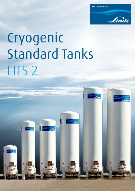
<strong>Cryogenic</strong><br />
<strong>Standard</strong> <strong>Tanks</strong><br />
<strong>LITS</strong> 2
2<br />
Contents.<br />
3 Introduction<br />
4 <strong>Standard</strong> vacuum-insulated tanks<br />
5 Quality standards for cryogenic tanks<br />
Optional standards for enhanced quality<br />
6 Technical data - tanks for air gases LIN, LOX, LAR<br />
7 Technical data - tanks for carbon dioxide<br />
8 Features<br />
Highly effective operation<br />
Safety<br />
Easy operation<br />
Ergonomical position of controls and instruments<br />
Non-corroding transport and lifting devices<br />
10 Flow diagram - tanks for nitrogen, oxygen, argon<br />
11 Flow diagram - tanks for carbon dioxide<br />
12 Clip-on standard design<br />
Special VAP - Quality for specific use<br />
14 SHEQ - safety, health, environment and quality police<br />
15 Service and guarantee<br />
16 Contact<br />
Title-page: The <strong>Linde</strong> standard tanks
3<br />
Introduction.<br />
To an increasing extent, industrial gases such as<br />
oxygen, nitrogen and argon are delivered to customers<br />
in liquid form at cryogenic temperatures and<br />
stored by the customer in tanks before further use.<br />
The pressure ratings and sizes of these tanks have<br />
been standardised in accordance with the requirements<br />
of distribution logistics and economical series<br />
production.<br />
3
4<br />
<strong>Standard</strong> vacuum insulated tanks.<br />
The vacuum-insulated double wall tanks consist<br />
of two concentric vessels, an austenitic steel<br />
inner tank and an outer jacket in carbon steel<br />
with an anti-corrosion primer and a special environmentally<br />
friendly top coat. The interspace<br />
between inner and outer tank is evacuated and<br />
filled with insulating powder (perlite). An adsorbent<br />
is also added to maintain the vacuum<br />
in the insulation interspace.<br />
The standard tanks come in gross nominal water<br />
capacities from 3,160 litre to 61,620 litre. The<br />
maximum allowable working pressure for the<br />
inner vessels is 18, 22 or 36 bar gauge for design<br />
temperatures ranking from -196°C up to 20°C.<br />
All standard tanks have vertical configuration,<br />
requiring little space for installation.<br />
The pressure vessels are manufactured and tested<br />
in accordance with the Pressure Equipment Directive<br />
EU 97/23/EC and EN 13458. These codes<br />
are internationally accepted. Consequently, it will<br />
be much easier than before to install and use<br />
these tanks in and outside of the European Union.<br />
The <strong>Linde</strong> quality management system satisfies<br />
all elements of the ISO 9001 program. All produced<br />
tanks are subjected to inspection and<br />
quality control under supervision of independent<br />
inspection bodies.<br />
The operating pressure may be set up to 90 % of<br />
the maximum allowable working pressure and is<br />
automatically maintained constant by the regulator<br />
and pressure building coil fitted to the tank.<br />
Each tank can also be equipped with a tank<br />
mounted (clip-on) air-heated vaporiser to<br />
supply product in gaseous form at ambient<br />
temperatures and flow rates up to 120 Nm 3 /h.<br />
<strong>Standard</strong> tank features are various fittings for<br />
transportation and installation. Vaporisers up<br />
to 1,000 Nm 3 /h are installed separately.<br />
Based on the standard design, <strong>Linde</strong> offers additional<br />
features depending on client´s requirements.<br />
<strong>Standard</strong> carbon dioxide tanks are very similar<br />
to the tanks for air gases. As a function of the<br />
application and customer’s request you have<br />
here the choice between an inner vessel either<br />
manufactured from a low temperature resistant<br />
austenitic steel or a fine grain carbon steel. The<br />
insulation system is equal to the system which<br />
is used for the air gas tanks.<br />
CO 2 -tanks, equipped with an inner vessel made<br />
out of a low temperature resistant austenitic<br />
steel can therefore also be used as multi-purpose<br />
storage for other industrial gases.<br />
<strong>Linde</strong> owns long standing experience in handling<br />
other liquefied gases such as for example<br />
LNG and hydrogen. <strong>Tanks</strong> for these gases are<br />
engineered and manufactured according to customers<br />
specifications, therefore quotations will<br />
be elaborated from case to case.<br />
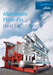
Arrangements of valves, pipes and instrumentation
5<br />
Quality standards for cryogenic tanks.<br />
Quality management and inspection is based<br />
on the following guiding principles:<br />
Quality management and inspection is an indispensable<br />
part of our corporate strategy and<br />
therefore a managerial responsibility carried<br />
out at all levels of the company. We consider the<br />
improvement of our product quality and the continued<br />
development of our quality management<br />
system as a permanent challenge.<br />
The Schalchen Plant is certified according to:<br />
– EN ISO 9001/2000<br />
– ASME (U, U2, R-Stamp)<br />
– Manufacture license of special equipment<br />
People‘s Republic of China and others<br />
Acceptance inspection is carried out by the<br />
experts of the Notified Body acc. to the valid<br />
(international) laws and further by <strong>Linde</strong>´s<br />
own specialists.<br />
Optional standards for enhanced quality<br />
Depending on customer requirements the tanks are<br />
available in two enhanced quality degrees:<br />
Quality degree Technical detail Applications<br />
HQ<br />
Degree for media – Inner vessel stainless steel High demands in semiconductor<br />
with purity >5.0 – Inner vessel and pipes pickled industry and research<br />
– Stainless steel cryogenic valves<br />
below sealed<br />
IQ<br />
Degree for corrosive – Inner vessel stainless steel Corrosive environment<br />
industrial environment<br />
– Stainless steel cryogenic valves<br />
with stuffing box
6<br />
Technical data - tanks for air gases LIN, LOX, LAR.<br />
Size 30 60 110 200 300 490 610 800<br />
Max. allowable working pressure air gases: 18 bar, 36 bar for LIN only<br />
Gross capacity approx. litre 3,160 6,365 11,535 20,355 30,205 49,020 61,620 80,360<br />
Net capacity approx. litre 18 bar 3,000 6,050 10,960 19,340 28,700 46,570 58,540 76,340<br />
36 bar 2,840 5,730 10,380 18,320 27,180 44,120 55,460<br />
Pressure stage<br />
18 bar, kg LIN 2,425 4,890 8,855 15,630 23,190 37,630 47,300 61,680<br />
filling ratio 95 %, 1 bar kg LOX 3,425 6,910 12,530 22,090 32,885 53,180 66,850<br />
kg LAR 4,185 8,440 15,290 26,980 40,040 64,965 81,660<br />
36 bar, kg LIN 2,300 4,630 8,390 14,800 21,970 35,650 44,810<br />
filling ratio 90 %, 1 bar kg LOX 3,250 6,540 11,850 20,920 31,050 50,390 63,340<br />
kg LAR 3,970 7,990 14,480 25,560 37,920 61,550 77,370<br />
Boil-off rate %/d LIN 0.67 0.58 0.44 0.31 0.30 0.21 0.20 0.19<br />
1 bar, 15°C A.T. %/d LOX 0.42 0.37 0.29 0.20 0.19 0.13 0.12<br />
referred to total capacity %/d LAR 0.46 0.40 0.32 0.21 0.21 0.15 0.14<br />
vacuum < 2 x 10 -2 mbar<br />
Discharge capacity with standard pressure building<br />
coil at 0,7 x MAWP and 8 hours operating time<br />
pressure stage<br />
18 bar m 3 /h (1 bar, 15°C) LIN 150 300 300 600 600 600<br />
m 3 /h (1 bar, 15°C) LOX 190 380 380 750 750<br />
m 3 /h (1 bar, 15°C) LAR 190 380 380 750 750<br />
36 bar m 3 /h (1 bar, 15°C) LIN 140 140 140 280 280<br />
m 3 /h (1 bar, 15°C) LOX 180 180 180 360 360<br />
m 3 /h (1 bar, 15°C) LAR 180 180 180 360 360<br />
Capacity of one safety valve at 1.1 x MAWP/cold condition<br />
pressure stage<br />
18 bar kg/h LIN 1,090 1,070<br />
kg/h LOX 1,010<br />
kg/h LAR 1,240<br />
36 bar kg/h LIN 5,610<br />
kg/h LOX 2,260<br />
kg/h LAR 2,850<br />
Insulation<br />
insulating powder (perlite), vacuum < 5 x 10 -2 mbar (tank in operation), status of delivery: 5 mbar<br />
Main material<br />
inner vessel: low temperature resistant austenitic steel<br />
outer vessel: carbon steel<br />
Main dimensions overall diameter 1,600 1,600 2,000 2,400 2,400 3,000 3,000 3,000<br />
overall hight 4,150 7,150 7,350 8,350 11,550 11,550 14,150 18,050<br />
Weight empty, kg 18 bar type 2,510 4,910 5,940 9,840 13,920 19,300 23,370 29,650<br />
36 bar type 2,600 5,220 7,180 12,310 17,090 24,570 30,260<br />
LIN = liquid nitrogen; LOX = liquid oxygen; LAR = liquid argon
7<br />
Technical data - tanks for carbon dioxide.<br />
Size 30 60 110 200 300 490 610<br />
Max. allowable<br />
working pressure<br />
CO 2 : 22 bar<br />
Gross capacity approx. litre 3,160 6,365 11,535 20,355 30,205 49,020 61,620<br />
Net capacity approx. litre 2,940 5,920 10,730 18,930 28,090 45,590 57,310<br />
Filling ratio 93 %, 1 bar kg CO 2 3,120 6,280 11,370 20,065 29,780 48,330 60,740<br />
Boil-off rate<br />
1 bar, 15°C A.T. %/d CO 2 0.22 0.19 0.14 0.10 0.10 0.07 0.06<br />
referred to total capacity<br />
vacuum < 2 x 10 -2 mbar<br />
Discharge capacity with standard<br />
pressure building coil at 0.7 x MAWP<br />
and 8 hours operating time<br />
pressure stage<br />
22 bar kg/h (1 bar, 15°C) CO 2 70 140 140 280 280<br />
Capacity of one safety valve<br />
at 1.1 x MAWP/cold condition<br />
pressure stage<br />
22 bar kg/h, CO 2 975<br />
Insulation<br />
insulating powder (perlite),<br />
vacuum < 5 x 10 -2 mbar (tank in operation)<br />
status of delivery: 5 mbar<br />
Main material<br />
inner vessel: low temp. resistant austenitic steel<br />
outer vessel: carbon steel<br />
Main dimensions overall diameter 1,600 1,600 2,000 2,400 2,400 3,000 3,000<br />
overall hight 4,150 7,150 7,350 8,350 11,550 11,550 14,150<br />
Weight empty, kg 22 bar Type 2,510 4,910 6,300 10,250 14,500 20,500 24,800
8<br />
Features.<br />
Highly effective operation<br />
Two service valves provide an exchange possibility<br />
for the filling valves even if the tank is<br />
filled.<br />
Integrated pressure building coil for standard<br />
discharge capacities (service valves see flow<br />
diagrams: valve 2 pressure building and valve<br />
13 gas shut-off). The tank also has an optimized<br />
design to reduce ice formation.<br />
Safety<br />
In case that the safety valves will release product,<br />
the medium will be blown off to a safe place.<br />
Easy operation<br />
All valves required for operation are set in one line
9<br />
Ergonomical position of controls<br />
and instruments<br />
The tank controls and instruments are set<br />
in two lines.<br />
– Operation line:<br />
Operation controls and instruments<br />
– Service line:<br />
Service controls and instruments<br />
– Weather protection for instruments<br />
The operation controls and instruments can be<br />
operated by the user. A white handwheel is<br />
fixed on top of this instruments and will be used<br />
for filling or extraction.<br />
The service controls and instruments will be<br />
used by trained employees of the gas supplier<br />
only. These valves are marked with a green<br />
handwheel.<br />
Non-corroding transport and lifting devices<br />
Stainless steel transport legs<br />
Additional vent valve (for T.. V110 - T.. V610)<br />
Lifting lugs with stainless steel inlay
10<br />
Flow diagram - tanks for nitrogen, oxygen, argon.<br />
Instrumentation and equipment, standard<br />
Valves, standard<br />
C/1 Fill coupling<br />
C/4, C/6 Connection add. transmitter<br />
C/PI Test connection pressure indicator<br />
D<br />
Pressure building coil<br />
I<br />
Inner vessel<br />
IN<br />
Insulation<br />
LI<br />
Level indicator<br />
L/11-1 Pipeline discharge<br />
L/11-2 Pipeline discharge (plugged)<br />
L/11-3 Pipeline discharge (plugged)<br />
NRV Non return valve<br />
O<br />
Outer vessel<br />
PC Pressure controller<br />
PI<br />
Pressure indicator<br />
RV/O Relief valve-outer vessel<br />
SV1, SV2 Safety valve<br />
1 Filling<br />
2 Pressure building valve<br />
3 Vent valve<br />
4 Bottom gauge (+)<br />
5 Gauge bypass<br />
6 Top gauge (-)<br />
9-1 Evacuation connection<br />
11 Discharge<br />
12 Top filling<br />
13 Gas shut-off<br />
18 Change over<br />
21 Trycock<br />
Options<br />
SAA Safety shut-off valve,<br />
control line for SAA<br />
LI(T) Level indicator Samson Media 6<br />
incl. instrument panel and standard<br />
programming,<br />
extra programming of Samson Media 6<br />
acc. to customer requirements<br />
LI(T) Level indicator WIKA with transmitter<br />
output 4 - 20 mA<br />
(1) only T ... V110 - T ... V800<br />
(2) only T18 V200 - T18 V800
11<br />
Flow diagramm - tanks for carbon dioxide.<br />
Instrumentation and equipment, standard<br />
Valves, standard<br />
C/3 Vent coupling<br />
C/4, C/6 Connection add. transmitter<br />
C/PI Test connection pressure indicator<br />
D<br />
Pressure building coil<br />
I<br />
Inner vessel<br />
IN<br />
Insulation<br />
LI(T) Level indicator<br />
L/11-1 Pipeline discharge<br />
L/11-2 Pipeline discharge (plugged)<br />
NRV Non return valve<br />
O<br />
Outer vessel<br />
PC Pressure controller<br />
PI<br />
Pressure indicator<br />
RV/O Relief valve-outer vessel<br />
SV1, SV2 Safety valve<br />
1 Filling<br />
2 Pressure building valve<br />
3 Vent<br />
4 Bottom gauge (+)<br />
5 Gauge bypass<br />
6 Top gauge (-)<br />
9-1 Evacuation connection<br />
11 Discharge<br />
12 Top filling<br />
13 Gas shut-off<br />
18 Change over<br />
21 Trycock<br />
26 Pressuring<br />
Options<br />
SAA Safety shut-off valve,<br />
control line for SAA<br />
LI(T) Level indicator Samson Media 6<br />
incl. instrument panel and standard<br />
programming,<br />
extra programming of Samson Media 6<br />
acc. to customer requirements<br />
LI(T) Level indicator WIKA with transmitter<br />
output 4 - 20 mA
12<br />
Clip-on standard design.<br />
Special VAP - Quality for specific use.<br />
The vaporisers are suitable for a design overpressure<br />
= max. allowable working pressure (PS)<br />
of 40 bar and an allowable operating temperature<br />
range (TS) of -269°C/+50°C.<br />
Design and testing was carried out in accordance<br />
with the directive 97/23/EC concerning<br />
pressure equipment, AD 2000-Merkblätter and<br />
DIN EN.<br />
Explanation of type designation:<br />
L = air heated<br />
40 = max. permissible working overpressure:<br />
40 bar<br />
8 F = number of Finned tubes: 8<br />
2,5 = length of single finned tube: 2,5 m<br />
The <strong>Linde</strong> finned tubes and connecting flanges<br />
are made of aluminium alloy and the seals are<br />
formed according to <strong>Linde</strong> <strong>Standard</strong>s.<br />
Clip-on standard design means the vaporiser<br />
without frame. Upon customer request, a mounting<br />
kit for installation on a cryo-tank is available.<br />
Type L 40 - 4 F 2,5<br />
Mounting kit<br />
Type L 40 - 2 F 2,5<br />
vaporiser type dimensions approx. weight empty<br />
nominal<br />
connections<br />
capacity* )<br />
(inlet/outlet)<br />
<strong>Linde</strong> ident-no.<br />
depth [m] widht [m] height[m] [kg] N 2 [Nm³/h] [mm]<br />
L 40 - 8 F 2,5 1,67 0,516 2,733 140 120<br />
screwed: M40 x 2<br />
J34895<br />
L 40 - 4 F 2,5 1,67 0,276 2,733 74 60<br />
pipe: DN 15 (21,3 x 1,5)<br />
socket welding end: ø18,2<br />
I32740<br />
L 40 - 2 F 2,5 0,69 0,276 2,709 37 30<br />
material: stainless steel<br />
I32631<br />
*) The capacity is based on an ambient temperature of 20°C, 70 % rel. humidity, 15°C temperature difference between ambient and gas outlet temperature at a continuous 8-hours-operation
14<br />
SHEQ - safety, health, environment<br />
and quality police.<br />
At the <strong>Engineering</strong> Division, we do not want to<br />
harm people or the environment. We will comply<br />
with all applicable legal, regulatory, internal<br />
and industry requirements.<br />
We strive to be leading in SHEQ to meet safe,<br />
secure and healthy working conditions and<br />
supplying safe, compliant and environmentally<br />
responsible products and services for our<br />
customers.<br />
SHEQ is a key part of The <strong>Linde</strong> Group’s overall<br />
strategy and we will also require our contractors<br />
and partners to manage in line with this policy.<br />
To achieve this vision,<br />
SHEQ is 100 % of our<br />
behaviour,<br />
100 % of the time.
15<br />
Service and guarantee.<br />
Welcome to the <strong>Engineering</strong> Division<br />
The <strong>Linde</strong> Schalchen Plant is located 100 km<br />
east of Munich, Germany. 700 engineers and<br />
skilled workers design and manufacture components<br />
and complete modules for the application<br />
in process plants.<br />
Backed up by more than 100 years of production<br />
know-how, highly developed plant modules are<br />
manufactured. Our innovative technologies and<br />
our competitiveness open the door to participation<br />
in prestigious plant projects worldwide.<br />
<strong>Linde</strong> provides complete services on field installation<br />
and operation. A specialised service crew<br />
is available for immediate and professional<br />
repair services.<br />
Do you need further and more<br />
detailed information?<br />
Just ask us – we will be pleased to help you.<br />
<strong>Linde</strong> AG<br />
<strong>Engineering</strong> Division<br />
Schalchen Plant<br />
Carl-von-<strong>Linde</strong>-Strasse 15<br />
83342 Tacherting/Germany<br />
Phone: +49.8621.85-6434<br />
Fax: +49.8621.85-6622<br />
E-Mail: plantcomponents@linde-le.com<br />
Internet: www.linde.de<br />
Production area<br />
of standardised equipment:<br />
– Advice and sale<br />
Phone: +49.8621.85-6777<br />
– After sales service, guarantee, spare parts<br />
Phone: +49.8621.85-6279<br />
Other products by production area<br />
of standardised equipment:<br />
– Static vacuum insulated cryogenic vessels<br />
– Spiral welded pipes
Designing processes – constructing plants.<br />
<strong>Linde</strong>´s <strong>Engineering</strong> Division continuously develops extensive process engineering know-how in the planning,<br />
project management and construction of turnkey industrial plants.<br />
The range of products comprises:<br />
− Petrochemical plants<br />
− LNG and natural gas processing plants<br />
− Synthesis gas plants<br />
− Hydrogen plants<br />
− Gas processing plants<br />
− Adsorption plants<br />
− Air separation plants<br />
− <strong>Cryogenic</strong> plants<br />
− Biotechnology plants<br />
− Furnaces for petrochemical plants and refineries<br />
More than 4,000 plants worldwide document the leading position of the <strong>Engineering</strong> Division in international<br />
plant construction.<br />
Production facilities.<br />
At <strong>Linde</strong> <strong>Engineering</strong> Schalchen Plant over 700<br />
skilled engineers and workers design and manufacture<br />
components and complete modules for<br />
numerous applications in process plants such as<br />
ethylene plants, hydrogen and synthesis gas<br />
plants, LNG plants and air separation plants. Production<br />
capacity totals approx. 1.3 million hours<br />
per year.<br />
In addition, the plant offers services for field installation<br />
and advice on operation. A specialised<br />
service crew is available for immediate and professional<br />
repair services.<br />
Product range.<br />
– Aluminium plate-fin heat exchangers as<br />
single units or as manifolded assemblies<br />
– Cold boxes with aluminium plate-fin heat<br />
exchangers, columns and vessels<br />
– Coil-wound heat exchangers and isothermal<br />
reactors for chemical and petrochemical<br />
plants<br />
– Columns and pressure vessels in aluminium<br />
for cryogenic plants<br />
– Spiral-welded pipes in aluminium<br />
– Storage tanks for liquefied gases<br />
– Steam-heated waterbath vaporisers as well<br />
as air-heated vaporisers for liquefied gases<br />
For further informations please contact:<br />
<strong>Linde</strong> AG<br />
<strong>Engineering</strong> Division, Schalchen Plant<br />
Carl-von-<strong>Linde</strong>-Strasse 15, 83342 Tacherting, Germany<br />
Phone +49.8621.85-6434, Fax +49.8621.85-6622<br />
E-Mail: plantcomponents@linde-le.com, www.linde-plantcomponents.com<br />
P/3.3.e/12