SATELLINE® -3AS(d) - Satel Norge
SATELLINE® -3AS(d) - Satel Norge
SATELLINE® -3AS(d) - Satel Norge

Create successful ePaper yourself
Turn your PDF publications into a flip-book with our unique Google optimized e-Paper software.
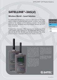
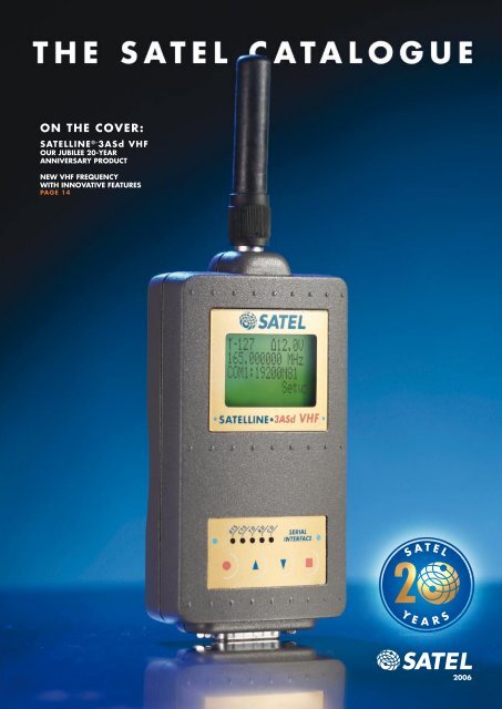
ON THE COVER:<br />
SATELLINE ®- <strong>3AS</strong>d VHF<br />
OUR JUBILEE 20-YEAR<br />
ANNIVERSARY PRODUCT<br />
NEW VHF FREQUENCY<br />
WITH INNOVATIVE FEATURES<br />
PAGE 14<br />
2006<br />
1
S A T E L C E L E B R A T I N G<br />
2 0 t h A N N I V E R S A R Y<br />
This year, 2006, marks our<br />
20th year of operation. It has<br />
been a long but rewarding time<br />
for us all. Our company began<br />
October 3,1986 with just me<br />
and two other persons. Today,<br />
the company employs 55 professionals.<br />
The customer base<br />
has expanded from a few local<br />
companies to today’s global<br />
market. For our growth, I thank<br />
our customers and partners<br />
who have trusted in our skills<br />
and the quality of services we<br />
provide.<br />
NEW PRODUCTS<br />
In this catalogue, you will find<br />
our latest developments, many<br />
of them marked as new. The<br />
SATELLINE-<strong>3AS</strong> VHF Radio Modem<br />
is our Product of the Year.<br />
This long-anticipated product<br />
fills a key frequency that has<br />
been requested by many customers.<br />
The SATELLINE radio<br />
modems have became a “de<br />
facto” standard in our business.<br />
We have redeveloped many<br />
products to provide improved<br />
performance. Along with our<br />
new application-specific products,<br />
we offer new OEM products<br />
to our key customers.<br />
I hope you enjoy this new edition<br />
of our catalogue.<br />
—Pekka Aura<br />
Founder and CEO<br />
D I D Y O U K N O W ?<br />
WHAT DO SATEL RADIOS DO?<br />
SATEL radios are used in place of a<br />
data cable and can reach distances<br />
of up to tens of kilometers, depending<br />
on the terrain and output power.<br />
If this isn’t long enough, the radios<br />
can be set to act as repeaters to extend<br />
the range over any distance.<br />
SATEL radio modems are used for a<br />
multitude of applications in numerous<br />
sectors of our everyday life. The security<br />
applications, for example, extend<br />
from extensive surveillance systems<br />
used to protect private or public property<br />
against crime. Radio modems<br />
are also used for a number of remote<br />
control applications, including haulage<br />
trucks in mines and snow guns<br />
on skiing slopes.<br />
I WANT TO USE SATEL IN A UNIQUE<br />
WAY, CAN YOU HELP?<br />
Most of our customers use SATEL for<br />
very specialized applications. We<br />
can meet most all specifications.<br />
B e c a u s e t h e r e a r e u n l i m i t e d<br />
applications, SATEL has adapted the<br />
policy of providing every product<br />
with a reasonable number of parallel<br />
versions. Our mission is to help our<br />
customers solve their local area data<br />
communication problems. This is why<br />
we are always open to the response<br />
and wishes from our customers.<br />
Send your specs and we’ll be happy<br />
to assist you!<br />
WHO USES SATEL?<br />
Public and private enterprises<br />
worldwide use SATEL. Anywhere a<br />
wireless data link is needed, SATEL<br />
has a solution. Industries use SATEL<br />
in their manufacturing process; utilities<br />
use SATEL for energy and water<br />
systems, and dispatchers use SATEL<br />
to track fleets of vehicles with GPS<br />
linking. We are a leading supplier in<br />
Europe and are currently extending<br />
our business into other market areas.<br />
During the past years, our sales have<br />
steadily grown 20 to 50 percent per<br />
annum.<br />
WHAT IS SATEL’S HISTORY?<br />
SATEL Oy, established in 1986,<br />
is a Finnish electronics and telecommunications<br />
company that specialises<br />
in the design, manufacturing,<br />
and international marketing of radio<br />
modems for data communication and<br />
alarm systems. One of the cornerstones<br />
of SATEL’s success is the experienced<br />
personnel—many of whom<br />
have devoted a major part of their<br />
working lives to wireless data communications<br />
technology. Our product<br />
development team is known for its innovativeness,<br />
efficiency, and impeccable<br />
quality control. Consequently,<br />
SATEL possesses the world’s widest<br />
selection of products in its field.<br />
2
CONTENTS<br />
PRODUCT GUIDES<br />
APPLICATIONS 4<br />
See how SATEL is used<br />
TYPE APPROVALS 5<br />
See where SATEL is type approved<br />
HOW TO SELECT YOUR ANTENNA 25<br />
Basic steps in antenna selection<br />
NETWORK DESIGN CENTER 26<br />
A new professional resource<br />
PLANNING A NETWORK 27<br />
Basic steps in network planning<br />
DISTRIBUTORS 28<br />
Locate your nearest distributor<br />
OEM PRODUCTS 16<br />
Use SATEL in your next OEM project<br />
SATELLINE ® PRODUCTS<br />
A modem for every occasion<br />
SATELLINE-1870 6<br />
SATELLINE-2ASc 7<br />
SATELLINE-2ASxE 8<br />
SATELLINE-<strong>3AS</strong>(d) 9<br />
SATELLINE-<strong>3AS</strong>(d) 869 9<br />
SATELLINE-<strong>3AS</strong>(d) EPIC 10<br />
SATELLINE-<strong>3AS</strong>(d) NMS 12<br />
SATELLINE-<strong>3AS</strong>(d) VHF 14<br />
ACCESSORIES<br />
A full line of accessories complement<br />
your radio modem and radio<br />
modem network<br />
SATEL-321 22<br />
HOUSING & POWER 22<br />
CABLES 23<br />
ANTENNAS 24<br />
ASP PRODUCTS<br />
C-LINK 19<br />
ESERV-10S 17<br />
I-LINK 19<br />
IP-LINK 17<br />
MINI-LINK 20<br />
SATELLINK PC PRO 21<br />
SATELCODE 8i 18<br />
SATELNODE X8SR 18<br />
WIRELESS M2M PACKAGE 20<br />
©2006 SATEL OY. All rights to this catalogue<br />
are owned solely by SATEL OY (referred to in<br />
this catalogue as SATEL). All rights reserved.<br />
The copying of this catalogue (without the<br />
written permission from the owner) by printing,<br />
copying, recording or by any other means, or<br />
the full or partial translation of the manual to<br />
any other language, including all programming<br />
languages, using any electrical, mechanical,<br />
magnetic, optical, manual or other methods<br />
or devices is forbidden. SATEL reserves<br />
the right to change the technical specifications<br />
or functions of its products, or to discontinue<br />
the manufacture of any of its products or to<br />
discontinue the support of any of its products,<br />
without any written announcement and urges<br />
its customers to ensure, that the information at<br />
their disposal is valid. SATEL software and programs<br />
are delivered ”as is”. The manufacturer<br />
does not grant any kind of warranty including<br />
guarantees on suitability and applicability to<br />
a certain application. Under no circumstances<br />
is the manufacturer or the developer of a program<br />
responsible for any possible damages<br />
caused by the use of a program. The names of<br />
the programs as well as all copyrights relating<br />
to the programs are the sole property of SATEL.<br />
Any transfer, licensing to a third party, leasing,<br />
renting, transportation, copying, editing,<br />
translating, modifying into another programming<br />
language or reverse engineering for any<br />
intent is forbidden without the written consent<br />
of SATEL.<br />
IMPORTANT<br />
S AT E L P R O D U C T S H AV E N O T B E E N<br />
DESIGNED, INTENDED NOR INSPECTED<br />
T O B E U S E D I N A N Y L I F E S U P P O RT<br />
RELATED DEVICE OR SYSTEM RELATED<br />
FUNCTION NOR AS A PART OF ANY OTHER<br />
CRITICAL SYSTEM AND ARE GRANTED<br />
NO FUNCTIONAL WARRANTY IF THEY<br />
ARE USED IN ANY OF THE APPLICATIONS<br />
MENTIONED.<br />
3
H O W T O U S E S A T E L<br />
APPLICATIONS<br />
The usual applications include<br />
telemetry as well as remote control<br />
and surveillance. The radio<br />
modems are typically placed at<br />
locations to which cable connection<br />
is impossible or too costly to<br />
build. A wireless connection is<br />
flexible and easy to install. The<br />
distance between the stations<br />
included in a wireless communications<br />
network is scaleable<br />
in both point-to-point and<br />
point-to-multipoint applications.<br />
Ordinary range of direct contact<br />
is several kilometres. Longer distances<br />
can be handled by routing<br />
the message through radio<br />
modems acting as repeaters.<br />
GPS: Send data several<br />
kilometres between<br />
GPS base and rover.<br />
Agriculture: SATEL<br />
data radios control<br />
irrigation equipment<br />
using GPS.<br />
Ports: Identify and<br />
control positions of<br />
shipping containers in<br />
ports and canals.<br />
Gas and Oil: Monitor<br />
data and control<br />
flow in remote positions.<br />
Construction: SATEL<br />
data radios control<br />
graders using GPS.<br />
Industrial Applications:<br />
SATEL Data Radios use<br />
PROFIBUS to control trains,<br />
trolleys, rotators, etc.<br />
Airports: Control traffic<br />
signs, security gateways,<br />
weather stations, fuel stations,<br />
and terminal gates.<br />
Fleet Management: Track<br />
locations and send messages<br />
to city busses, cabs, emergency<br />
vehicles, and patrol cars.<br />
Surveying: Use your own<br />
instrument and data collector<br />
to operate your data collector<br />
from the pole.<br />
Highway Signs: Warn motorists<br />
of road conditions and<br />
area alerts. Control traffic by<br />
changing posted speed.<br />
4
T Y P E A P P R O V A L S<br />
COUNTRY<br />
Australia<br />
Austria<br />
Belgium<br />
Brazil<br />
Canada<br />
Croatia<br />
Cyprus<br />
Czech<br />
Denmark<br />
Estonia<br />
Finland<br />
France<br />
Germany<br />
Greece<br />
Hong Kong<br />
Hungary<br />
Iceland<br />
India*<br />
Indonesia<br />
Ireland<br />
SATELLINE-2ASc<br />
SATELLINE-2ASxE<br />
SATELLINE-<strong>3AS</strong> (d)<br />
SATELLINE-<strong>3AS</strong> (d) Epic<br />
SATELLINE-<strong>3AS</strong> (d) 869<br />
SATELLINE-1870<br />
b b b<br />
b b b b b b<br />
b b b b b b<br />
b<br />
b b b<br />
b b b b b b<br />
b b<br />
b b b b b b<br />
b b b b b b<br />
b b b b b b<br />
b b b b b b<br />
b b b b b b<br />
b b b b b b<br />
b b b b b b<br />
b b<br />
b b b b b b<br />
b b b b b b<br />
b b<br />
b b b b b b<br />
COUNTRY<br />
Kazakhstan*<br />
Korea**<br />
Latvia<br />
Lithuania<br />
Malaysia<br />
Mexico<br />
Malta<br />
Netherlands<br />
Norway<br />
Poland<br />
Portugal<br />
Romania<br />
Russia<br />
Singapore<br />
Slovak Republic<br />
Slovenia<br />
South Africa<br />
Spain<br />
Sweden<br />
Switzerland<br />
SATELLINE-2ASc<br />
SATELLINE-2ASxE<br />
SATELLINE-<strong>3AS</strong> (d)<br />
SATELLINE-<strong>3AS</strong> (d) Epic<br />
SATELLINE-<strong>3AS</strong> (d) 869<br />
SATELLINE-1870<br />
b<br />
b b b b b b<br />
b b b b b b<br />
b b b<br />
b<br />
b b b b b b<br />
b b b b b b<br />
b b b b b b<br />
b b b b b b<br />
b b b b b b<br />
b b b<br />
b b<br />
b b<br />
b b b b b<br />
b b b b b<br />
b b b b b<br />
b b b b b b<br />
b b b b b b<br />
b b b b b b<br />
TYPE APPROVALS<br />
SATELLINE radio modems are typeapproved<br />
in most European countries<br />
and globally. Type approvals ensure<br />
frequency compatibility with other<br />
uses of the radio spectrum in a given<br />
country. The table on this page show<br />
where SATELLINE modems are currently<br />
type-approved. If you would<br />
like to use a product that is not<br />
currently type-approved with your<br />
national government, contact your<br />
local distributor. Your distributor may<br />
already be in the process of securing<br />
approval.<br />
RoHS COMPLIANCE<br />
Restriction of Hazardous Substances<br />
(RoHS) is a restriction on the use of<br />
certain hazardous substances in electrical<br />
or electronic equipment sold or<br />
used in the European Union after July<br />
1, 2006. These substances are lead,<br />
mercury, cadmium, hexavalent chromium,<br />
polybrominated biphenyls,<br />
and polybrominated diphenyl ethers.<br />
SATEL products meets the EU directive<br />
2002/95/EC on the RoHS and<br />
directive 2002/96/EC on Waste<br />
Electrical and Electronic Equipment<br />
(WEEE). If you require further information<br />
regarding type approvals or<br />
RoHS, please do not hesitate to contact<br />
your local distributor.<br />
COUNTRY<br />
Turkey<br />
UK<br />
Ukraine<br />
USA<br />
Vietnam<br />
SATELLINE-2ASc<br />
SATELLINE-2ASxE<br />
SATELLINE-<strong>3AS</strong> (d)<br />
SATELLINE-<strong>3AS</strong> (d) Epic<br />
SATELLINE-<strong>3AS</strong> (d) 869<br />
b b b b<br />
SATELLINE-1870<br />
b b b b b b<br />
b b<br />
b b<br />
b b<br />
Israel<br />
b b<br />
Thailand<br />
b b b<br />
*Project approval to be applied case–by–case.<br />
**Special versions only for Korea available.<br />
Italy<br />
b b b b b b<br />
Taiwan*<br />
NOTE! Check the SATELLINE-<strong>3AS</strong> VHF<br />
type approvals at www.satel.com<br />
5
S A T E L L I N E ® - 1 8 7 0<br />
KEY FEATURES<br />
b Low power, low range<br />
perfect for indoor applications.<br />
b Operates on a licensefree<br />
frequency band in<br />
Europe.<br />
b RS-232 interface<br />
compatible, software<br />
programmable.<br />
SATELLINE ® -1870<br />
SATELLINE-1870 is the most economical and smallest<br />
member of the SATELLINE radio modem family. Thanks to<br />
its small size, as well as low output power consumption,<br />
the SATELLINE-1870 is particularly well-suited for internal<br />
applications within factories.<br />
LICENSE-FREE FREQUENCY<br />
The SATELLINE-1870 uses the pan-European free 868<br />
to 870 MHz frequency band. This band is divided into<br />
sub-bands according to the output power and duty cycle<br />
allowed for the transmitter. When changing the frequency<br />
the user need not worry about the output power limitation;<br />
the modem automatically sets the output power according<br />
to the regulations. Due to the limited output<br />
power, the radio’s range is 5 kilometres, depending<br />
on surroundings. By using repeater<br />
stations and multiple addresses, the range of<br />
the radio modem network can be extended.<br />
SPECIAL FEATURES<br />
SATELLINE-1870 is compatible with RS-232<br />
interface. The modem can be connected to<br />
a terminal with a ribbon cable or by wiring<br />
a D9 connector. Like the preceding models,<br />
assembling is performed with 2.5 mm screws,<br />
Velcro ® , tape or the DIN-rail with a special<br />
installation kit. The settings of the SATELLINE-<br />
1870 radio modems can be modified by SL-commands<br />
in the normal communication mode or through an external<br />
terminal in programming mode. The software of the<br />
SATELLINE-1870 resides in a flash memory. The flash<br />
memory is easily re-programmable through a programming<br />
device.<br />
SATELLINE-1870<br />
Antenna 1870<br />
1870 TECHNICAL SPECIFICATIONS<br />
TRANSMITTER-RECEIVER<br />
YM4000<br />
YA1869<br />
Frequency Range<br />
868 … 870 MHz (programmable)<br />
Channel Spacing<br />
25 kHz<br />
No. Of Channels 74<br />
Communication Mode Half-duplex<br />
TRANSMITTER<br />
Carrier Power<br />
RECEIVER<br />
Sensitivity<br />
5, 10, 25, 50, 100 mW / 50 ohm<br />
< -108 dBm (BER 10E-3)<br />
DATA MODEM<br />
Interface<br />
RS-232<br />
Interface connector<br />
DIN41651-16pin (male)<br />
Data speed of RS Interface 300 – 19200 bps (programmable)<br />
Data speed of radio interface 9600 bps<br />
Data Formats Asynchronous RS-232<br />
GENERAL<br />
Operating Voltage<br />
Antenna Connector<br />
+ 8 ... + 30 Vdc<br />
SMA, 50 Ω, female<br />
6
S A T E L L I N E ® - 2 A S c<br />
SATELLINE ® -2ASc<br />
Primarily, the purpose of the 2ASc is to<br />
ensure network compatibility with the discontinued<br />
SATELLINE-1AS and 2AS radio<br />
modems. The SATELLINE-2ASc, a small,<br />
lightweight radio modem used for diverse<br />
applications in half-duplex data message<br />
transfer, features a synthesized 80-channel<br />
radio, operating in the 380-470 MHz frequency<br />
range. The accompanying RS-232<br />
interface facilitates trouble-free connections<br />
to many data terminals and systems.<br />
CHARACTERISTICS<br />
Data speed can be selected in the range 300-4800<br />
bits (25 kHz) or 300-2400 bits (20 kHz). There are two<br />
methods of initiating data relay with the SATELLINE-2ASc.<br />
Transmission can be activated with two methods—data<br />
coming from TD line activates the transmission, or by using<br />
RTS/CTS handshaking. RTS/CTS handshaking is only<br />
needed to be used when replacing existing 1AS / 2AS<br />
modems or in systems where timing demands usage of<br />
handshaking.<br />
SPECIAL FEATURES<br />
In the reception mode, a data squelch circuit built into<br />
the modem board of the SATELLINE-2ASc easily prevents<br />
imitation characters (from e.g. radio interference) from<br />
entering the RD line. The output signals from the radio<br />
modem include an analog RSSI (Received Signal Strength<br />
Indicator). This feature is especially useful.<br />
SATELLINE-2ASc<br />
YM0246<br />
KEY FEATURES<br />
b Compatible with 1AS<br />
& 2AS radio modems.<br />
b Compatible with RS-<br />
232.<br />
b 80 or 100 Channels.<br />
b 380-470 MHz.<br />
b Signal Strength<br />
Indicator.<br />
b Operating Voltage<br />
+9 to +30 Vdc<br />
2ASc TECHNICAL SPECIFICATIONS<br />
TRANSMITTER-RECEIVER<br />
Frequency Range 380...470 MHz<br />
Channel Spacing 20 or 25 kHz<br />
No. Of Channels 100 or 80<br />
TRANSMITTER<br />
Carrier Power<br />
RECEIVER<br />
Sensitivity<br />
Adjacent Channel<br />
Selectivity<br />
DATA MODEM<br />
Interface<br />
Interface connector<br />
Data speed of RS<br />
Interface<br />
Data Formats<br />
10 mW … 1 W / ohm (factory set)<br />
-110...-115 dBm (BER < 10 E-3)<br />
> 70 dB<br />
RS-232<br />
D15, female<br />
300-4800 bps (25 kHz)<br />
300-2400 bps (20 kHz)<br />
Asynchronous data<br />
Character length: 10 or 11 bits<br />
GENERAL<br />
Antenna Connector TNC, 50 ohm, female<br />
Operating Voltage +9 … +30 Vdc<br />
7
S A T E L L I N E ® - 2 A S x E<br />
SATELLINE-2ASxE<br />
SATELLINE-2ASxE is mostly used<br />
for local data communications in<br />
industrial and urban environments.<br />
Thanks to its small size it can easily<br />
be mounted and integrated into fixed<br />
and mobile terminals. Connection<br />
to customer’s terminals and systems<br />
is easy with the RS-232 Interface.<br />
SATELLINE-2ASxE is fully compatible<br />
with the SATELLINE-2ASxm2 radio<br />
modem.<br />
CHARACTERISTICS<br />
The function of SATELLINE-2ASxE is<br />
like a communication cable, except<br />
the data transfer happens in the halfduplex<br />
mode. The SATELLINE-2ASxE<br />
complies with the European specification<br />
ETS 300 113. The output power<br />
of the transmitter is 1 watt, and the<br />
sensitivity of the<br />
receiver is less than<br />
-115 dBm, which<br />
gives an operating<br />
range of tens of<br />
kilometers.The radio<br />
modem features data<br />
speed max 4800 or<br />
9600 bps depending<br />
on channel spacing. It can be<br />
operated at a voltage range of<br />
+9...+30 Vdc.<br />
OPERATING MODES AND<br />
AUXILIARY FUNCTIONS<br />
The SATELLINE-2ASxE has three<br />
modes of operation: programming<br />
mode, test mode, and data transfer<br />
mode. In the programming mode, the<br />
parameters and functions of the radio<br />
modem are set from a computer via<br />
the RS-232 interface. The data transfer<br />
mode of SATELLINE-2ASxE includes<br />
a command program function<br />
that allows the radio channel and<br />
addresses to be changed online from<br />
the serial port of the radio data modem.<br />
The radio modem is compatible<br />
with most protocols used worldwide.<br />
The SATELLINE-2ASxE radio modem<br />
also works as a repeater station, so<br />
KEY FEATURES<br />
b Compatible with<br />
RS-232.<br />
b Each radio can act as a<br />
repeater.<br />
b 380-470 MHz.<br />
b Tens of kilometres range.<br />
b 9600 bps maximum.<br />
wider coverage of the<br />
radio network is simple.<br />
In this function,<br />
it receives a data<br />
packet and transmits<br />
it over a longer distance<br />
as soon as it’s<br />
received.<br />
SOFTWARE<br />
SATELLINE-2ASxE uses programmable<br />
software with many functions<br />
and settings. Controlling the radio<br />
modem’s operating status is as convenient<br />
as using a PC—you simply<br />
set a table of parameters with an<br />
RS-232 interface from any personal<br />
computer.<br />
LOW VOLTAGE VERSION<br />
The SATELLINE-2ASxE is also available<br />
in a low voltage version. The<br />
range is from 6.5 to 8.5 Vdc with the<br />
nominal voltage being 7.2 Volts. The<br />
average power consumption is 160<br />
mA when receiving, 700 mA when<br />
transmitting, and 0.8 mA in standby<br />
mode. All the other technical specifications<br />
are the same as the standard<br />
version (+9...+30 Vdc).<br />
SATELLINE-2ASxE<br />
YM0236<br />
SATELLINE-2ASxE-7V2 (Low Voltage)<br />
YM0256<br />
2ASxE TECHNICAL SPECIFICATIONS<br />
TRANSMITTER-RECEIVER<br />
Frequency Range<br />
380...470 MHz<br />
Channel Spacing<br />
12.5 kHz, 20 kHz or 25 kHz<br />
No. Of Channels 160, 100 or 80<br />
TRANSMITTER<br />
Carrier Power<br />
Carrier Power Stability<br />
Frequency Deviation<br />
RECEIVER<br />
Maxium Usable Sensitivity<br />
Co-Channel Rejection<br />
Adjacent Channel Selectivity<br />
Intermodulation Attenuation<br />
Spurious Radiations<br />
DATA MODEM<br />
Interface<br />
Interface connector<br />
Data speed of RS Interface<br />
Data Formats<br />
GENERAL<br />
Antenna Connector<br />
10 mW ... 1 W / 50 ohm<br />
+ 2 dB / - 3 dB<br />
± 1.8 kHz or ± 3.0 kHz<br />
< - 115 (BER < 10 E-3)<br />
> - 8 dB<br />
> 60 dB / > 70 dB or > 70 dB<br />
> 65 dB<br />
< 2 nW<br />
RS-232<br />
Connector D 15, female<br />
1200...4800 bps (12.5/20 kHz channel)<br />
1200...9600 bps (25 kHz channel)<br />
Asynchronous data<br />
Character length: 10 or 11 bits<br />
TNC, 50 ohm, female<br />
8<br />
8
S A T E L L I N E ® - 3 A S & 3 A S d<br />
SATELLINE-<strong>3AS</strong> & <strong>3AS</strong>d<br />
The popular SATELLINE-<strong>3AS</strong> and <strong>3AS</strong>d radio modems<br />
make wireless networks of any size a possibility. These<br />
half-duplex radio modems are suitable for a vast variety<br />
of critical data applications that demand speed and precision.<br />
The SATELLINE-<strong>3AS</strong> software features<br />
selectable error correction, which improves<br />
the functioning of the radio under interference.<br />
A complete line of accessories, including<br />
weatherproof battery packs, housings,<br />
and antennas complement the <strong>3AS</strong> series.<br />
MESSAGE ROUTING<br />
Message Routing is a feature for the SATEL-<br />
LINE-<strong>3AS</strong> family of radio modems. It makes<br />
building large radio modem networks easier<br />
than ever before. Communication is fully<br />
transparent, which makes message routing<br />
directly compatible to most user protocols. Even though<br />
the network can cover large areas with multiple hops and<br />
repeater stations, only one radio channel is necessary.<br />
Any radio modem in the network can act as a repeater<br />
station, keeping infrastructure costs low.<br />
TECHNICAL SPECIFICATIONS<br />
TRANSMITTER-RECEIVER<br />
Frequency Range<br />
380...470 MHz<br />
Channel Spacing<br />
12.5 / 20 or 25 kHz<br />
No. Of Channels 160 /100 or 80<br />
Communication Mode Half-duplex<br />
TRANSMITTER<br />
Carrier Power<br />
RECEIVER<br />
Sensitivity<br />
Co-Channel Rejection<br />
DATA MODEM<br />
10 mW ... 1 W / 50 ohm<br />
< - 116 ... 110 dBm (BER < 10 E-3)<br />
> - 12 dB<br />
Interface<br />
RS-232 or RS-485, RS-422<br />
Interface connector<br />
Connector D 15, female<br />
Data speed of RS Interface 300 - 38400 bps<br />
Data speed of radio interface 19200 bps ( 25 kHz channel)<br />
9600 bps ( 12.5 kHz channel)<br />
Data Formats Asynchronous data<br />
GENERAL<br />
Operating Voltage<br />
Power Consumption<br />
Antenna Connector<br />
+ 9 ... +30 Vdc<br />
1.8 VA typical (Receive)<br />
6.0 VA typical (Transmit)<br />
0.05 VA (When DTR is “0”)<br />
TNC, 50 ohm, female<br />
RADIO NETWORK DESIGN<br />
With the included free SaTerm PC software you can<br />
graphically design a radio modem network, troubleshoot,<br />
and make radio modem firmware updates. With SaTerm<br />
it is possible to simply draw the connections between<br />
KEY FEATURES<br />
b Compatible with<br />
RS-232, RS-422 and<br />
RS-485<br />
b Each radio can be set to<br />
act as a repeater.<br />
b Included software makes<br />
setup easy.<br />
b Tens of kilometres range.<br />
b 19,200 bps maximum.<br />
radio modems, and the routing information<br />
is automatically generated. If<br />
access to a computer isn’t convenient,<br />
manual setup of the radio network can<br />
be configured directly via the <strong>3AS</strong>d<br />
radio modem’s LCD screen.<br />
FREE CHANNEL SCAN<br />
Free Channel Scan (FCS) is a new<br />
feature of SATELLINE-<strong>3AS</strong> modems. It<br />
is designed for one-way transmission<br />
between a transmitter and one or more<br />
receivers when there<br />
are multiple transmission frequencies<br />
available. The transmitter monitors the<br />
noise level of the channels between the<br />
transmissions and finds the best transmission<br />
channel. This feature is beneficial<br />
especially when license-free channels are<br />
used and there could be other transmitters<br />
using the same channels.<br />
LOW VOLTAGE VERSION<br />
The SATELLINE-<strong>3AS</strong> is also available<br />
in a low voltage version.<br />
The range is from 6.5 to 8.5<br />
Vdc with the nominal voltage<br />
being 7.2 Volts. The average<br />
power consumption is 160<br />
mA when receiving, 700 mA<br />
when transmitting, and 0.8 mA<br />
in standby mode. All the other<br />
technical specifications are the<br />
same as the standard version<br />
(+9...+30 Vdc).<br />
SATELLINE-<strong>3AS</strong><br />
YM1011<br />
SATELLINE-<strong>3AS</strong> Dual Band<br />
YM1012<br />
SATELLINE-<strong>3AS</strong>/7V2 (Low Voltage) YM1031<br />
SATELLINE-<strong>3AS</strong>d<br />
SATELLINE-<strong>3AS</strong>d Dual Band<br />
YM1016<br />
YM1017<br />
SATELLINE-<strong>3AS</strong>d/7V2 (Low Voltage) YM1033<br />
SATELLINE ® -<strong>3AS</strong> 869<br />
SATELLINE-<strong>3AS</strong> 869 uses the 869.4<br />
to 869.65 MHz frequency band.<br />
European Telecommunications Standards<br />
Institute (ETSI) has released a<br />
new frequency band for narrow and<br />
broadband ISM-purposes (industrial,<br />
scientific, and medical). The 868 to<br />
870 MHz band is divided into subbands<br />
according to transmit power<br />
(max 0.5W) and duty cycle allowed<br />
for the transmitter. This band has 10<br />
separate 25 kHz channels for a maximum<br />
power of 0.5 W ERP. Transmitter<br />
duty cycle of 10% and the maximum<br />
constant transmission time (max 36<br />
seconds) must be controlled by data<br />
terminal equipment. Other features of<br />
the SATELLINE-<strong>3AS</strong> 869 version are<br />
equivalent with the 450 MHz version.<br />
SATELLINE-<strong>3AS</strong>/869<br />
YM1021<br />
SATELLINE-<strong>3AS</strong>d/869<br />
Antenna 869<br />
YM1023<br />
YA0869<br />
9
®<br />
S A T E L L I N E<br />
- 3 A S E p i c<br />
SATELLINE ® -<strong>3AS</strong>(d) Epic<br />
SATELLINE-<strong>3AS</strong> Epic includes a high power 10 watt transmitter<br />
and two receivers. The powerful transmitter gives<br />
you better coverage and a potential 10 to 90 kilometer<br />
distance between stations. The modem automatically<br />
chooses the best signal from two independent receivers<br />
for greater signal reception. Compared to the regular<br />
SATELLINE-<strong>3AS</strong> radio modems, the Epic offers greater<br />
range and signal reliability; it more than doubles the distances<br />
between modems.<br />
DIVERSITY RECEPTION KEY FEATURES<br />
You don’t need to have a direct<br />
visual connection between the b 10 Watt transmitter offers<br />
master station and the moving potential 90 km range.<br />
substation because the radio b Diversity reception<br />
signal transmits by reflecting from improves reception.<br />
buildings and geography, like<br />
hills. The transmission speed of the radio signals is the<br />
speed of light, so signals reflecting off of different objects<br />
get to the receiver at different times. The signals at the receiving<br />
antenna come in different phases, so even in the<br />
worst case, two “opposite but equal” signals cancel each<br />
other out, causing fading. The dips of the signal appear<br />
with half-wave intervals. In connections based only on<br />
reflections, the reliability of the receiving signal depends<br />
on the position of the receiving antenna, even when it’s<br />
close to the base station. By setting the two antennas of<br />
the diversity receiver at least ¾ x wavelength apart from<br />
each other, the message can always be received by one<br />
of the receivers, if not both. This way they are rarely at the<br />
same time at the fading dips.<br />
<strong>3AS</strong> EPIC TECHNICAL SPECIFICATIONS<br />
TRANSMITTER-RECEIVER<br />
Frequency Range<br />
400 ... 470 MHz<br />
NEW POWER SAVE VERSION<br />
SATELLINE-<strong>3AS</strong> Epic is available also in a new Power<br />
Save Version. The power consumption in this version is<br />
1.7 VAMPS when receiving and when transmitting it is<br />
Channel Spacing<br />
No. Of Channels<br />
TRANSMITTER<br />
12.5 kHz or 25 kHz<br />
160 or 80<br />
Carrier Power<br />
1 ... 10 W / 50 ohm<br />
the same as the normal Epic. This feature is especially<br />
Carrier Power Stability + 2 dB / - 3 dB<br />
required, for instance, in applications where the power is<br />
generated by solar panels.<br />
RECEIVER<br />
SATELLINE-<strong>3AS</strong>(d) EPIC. ‘d’ STANDS FOR DISPLAY.<br />
SATELLINE-<strong>3AS</strong>/Epic<br />
SATELLINE-<strong>3AS</strong>d/Epic<br />
POWER SAVE VERSION<br />
SATELLINE-<strong>3AS</strong> Epic DB PWRS<br />
SATELLINE-<strong>3AS</strong> Epic C PWRS<br />
WITH HEAT SINK<br />
SATELLINE-<strong>3AS</strong>/Epic C<br />
SATELLINE-<strong>3AS</strong>d/Epic C<br />
DUAL BAND<br />
SATELLINE-<strong>3AS</strong>/Epic DB<br />
SATELLINE-<strong>3AS</strong>d/Epic DB<br />
DUAL BAND WITH HEAT SINK<br />
SATELLINE-<strong>3AS</strong>/Epic C DB<br />
SATELLINE-<strong>3AS</strong>d/Epic C DB<br />
YM3000<br />
YM3001<br />
YM3008<br />
YM3009<br />
YM3002<br />
YM3003<br />
YM3004<br />
YM3005<br />
YM3006<br />
YM3007<br />
Sensitivity<br />
Co-Channel Rejection<br />
Adjacent Channel Selectivity<br />
Intermodulation Attenuation<br />
Spurious Radiations<br />
Diversity Scheme<br />
DATA MODEM<br />
Interface<br />
Interface connector<br />
Data speed of RS Interface<br />
Data speed of Radio Interface<br />
Data Formats<br />
GENERAL<br />
-116 ... -110 dBm (BER < 10 E-3)<br />
> - 12 dB<br />
> 60 dB / > 70 dB<br />
> 65 dB<br />
< 2 nW<br />
Space diversity, selection combining<br />
RS-232 or RS-485, RS-422<br />
D15, female<br />
300—38400 bps<br />
19200 bps (25 kHz channel)<br />
9600 bps (12 kHz channel)<br />
Asynchronous data<br />
Power Consumption<br />
3 VA typical (Receive)<br />
25 VA typical (Transmit)<br />
Antenna Connector<br />
TNC, 50 ohm, female<br />
Temperature Range -25 °C to +55 °C<br />
10
S A T E L L I N E ® - 3 A S d N M S<br />
SATELLINE-<strong>3AS</strong>(d) NMS<br />
SATELLINE-<strong>3AS</strong> NMS introduces SATEL’s<br />
new concept of remotely manageable<br />
radio modems. In addition to ordinary<br />
communication functions, it allows remote<br />
configuration through the master radio,<br />
efficient diagnostics tools, and accumulation<br />
of operation statistics data.<br />
The management and surveillance of<br />
SATELLINE-<strong>3AS</strong>(d) NMS radio modem<br />
network is affected through the Master<br />
Station connected by a serial interface to<br />
a PC with dedicated Network Management<br />
software.<br />
The Network Management System provides<br />
easy configuration of the network<br />
and advance indication of faults for maximum<br />
reliability, labor-saving maintenance<br />
work, and efficient system management.<br />
The NMS radio modems monitor the quality<br />
of the radio connection, received signal<br />
strength (RSSI), and the voltage level<br />
of the power source, as well as the inner<br />
temperature of the modem, on a continuous<br />
basis. The information is transmitted<br />
to the SATEL NMS PC software, where the<br />
long-term logs of the operational data are<br />
stored. The software allows the followup<br />
of the trends and regularly occurring<br />
events.<br />
The Network Management System offers<br />
several significant benefits, including<br />
• Enhanced reliability, through<br />
advance indication of anticipated<br />
faults and failures<br />
• Reduced configuration and maintenance<br />
costs, through remote<br />
configuration<br />
• Efficient network development tool<br />
• Flexibility in adapting to customer<br />
protocols and applications<br />
A SATELLINE-<strong>3AS</strong> NMS network provides<br />
a solution to a variety of wireless data<br />
communications applications. It is especially<br />
suited for frequently changing networks<br />
and applications requiring utmost<br />
reliability, thanks to efficient monitoring<br />
of the signal quality and flexible use of<br />
alternative routing.<br />
Remote, continuous monitoring of the voltage<br />
level of the power source as well as<br />
the temperature of the radio modem provides<br />
early indication and the possibility<br />
of avoiding anticipated problems.<br />
SATELLINE-<strong>3AS</strong>d NMS<br />
SATELLINE-<strong>3AS</strong> NMS<br />
YM1070<br />
YM1075<br />
TECHNICAL SPECIFICATIONS<br />
TRANSMITTER-RECEIVER<br />
Frequency Range<br />
380…470 MHz<br />
Channel Spacing<br />
12.5 / 20 / 25 kHz<br />
No. Of Channels 160 / 100 / 80<br />
Communication Mode Half-duplex<br />
TRANSMITTER<br />
Carrier Power<br />
RECEIVER<br />
Sensitivity<br />
Co-Channel Rejection<br />
10mW…1W<br />
< - 116 ... 110 dBm (BER < 10 E-3)<br />
> - 12 dB<br />
DATA MODEM<br />
Interface<br />
RS-232, RS-485, or RS-422<br />
Interface connector<br />
D15, female<br />
Data speed of RS Interface 1200 - 38400 bps<br />
Data speed of radio interface 19200 bps ( 25 kHz channel)<br />
9600 bps ( 12.5 and 20 kHz channel)<br />
Data Formats Asynchronous data<br />
GENERAL<br />
Operating Voltage<br />
Power Consumption<br />
Antenna Connector<br />
+ 9 ... +30 Vdc<br />
1.4 VA typical (Receive)<br />
6.0 VA typical (Transmit)<br />
0.05 VA (When DTR is “0”)<br />
TNC, 50 ohm, female<br />
12<br />
12<br />
12
NETWORK<br />
MANAGEMENT<br />
SYSTEM (NMS)<br />
The new SATEL NMS improves your<br />
network’s reliability by allowing you<br />
to anticipate problems and even resolve<br />
them without needing to visit the<br />
site. Vital network statistics and modem<br />
settings are instantly accessible<br />
from your computer.<br />
SATEL NMS PC is a software tool<br />
designed by SATEL for assisting when<br />
configuring, monitoring, and diagnosing<br />
radio modem networks constructed<br />
with new SATELLINE-<strong>3AS</strong>(d)<br />
NMS or VHF modems. The program<br />
is compatible with Windows® 2000<br />
and Windows® XP operating systems.<br />
MONITORING AND<br />
DIAGNOSTICS<br />
SATEL NMS allows the modem<br />
network to be monitored constantly<br />
(online) while maintaining normal<br />
operations. SATEL NMS adds a small<br />
amount of diagnostics data to each<br />
packet sent by the network. A user’s<br />
data is not affected by SATEL NMS<br />
traffic.<br />
The system allows a real-time monitoring<br />
of several vital network diagnostics<br />
values, such as Received Signal<br />
Strength (RSSI) for each link direction,<br />
modem supply voltage, and<br />
operating temperature.<br />
SATEL NMS maintains log files for the<br />
monitored values and includes a log<br />
viewer window to show the values as<br />
a graph.<br />
RADIO MODEM<br />
CONFIGURATION<br />
SATEL NMS also replaces the terminal<br />
software SATERM, made by SATEL,<br />
as the network configuration tool for<br />
the new SATELLINE-<strong>3AS</strong>(d) NMS or<br />
VHF modems. The network is drawn<br />
on a PC screen by using an easy-touse<br />
graphical network designer, and<br />
the modem settings are automatically<br />
created. The modem settings are then<br />
initialized one-by-one using a serial<br />
cable between SATELLINE-<strong>3AS</strong>(d)<br />
NMS or VHF modem and PC before<br />
the final deployment to the field.<br />
Using SATEL NMS, it is possible to<br />
configure settings of any modem in<br />
a deployed network remotely from a<br />
central location.<br />
NETWORK DESIGN AND<br />
CONFIGURATION<br />
With the graphical interface of the<br />
SATEL NMS PC, the user can conveniently<br />
configure, add or remove radio<br />
modems, as well as draw message<br />
routes and set repeater links.<br />
All features of SATEL NMS may be<br />
activated while the user’s system is<br />
operational (online) or the system<br />
may be temporarily disabled (offline)<br />
while the maintenance and measurements<br />
are performed.<br />
13
S A T E L L I N E ® - 3 A S ( d ) V H F<br />
SATELLINE-<strong>3AS</strong> VHF<br />
with Heat Sink<br />
SATELLINE-<strong>3AS</strong>(d) VHF<br />
A SATELLINE-<strong>3AS</strong>(d) VHF network consists of<br />
remotely adjustable radio modems operated<br />
in a polling mode. It is controlled through the<br />
Master Station by dedicated SATEL NMS PC<br />
software. The user data and NMS information<br />
are transferred together seamlessly. The Network<br />
Management System is compatible with<br />
most user protocols, making the NMS network<br />
suitable for numerous applications.<br />
SATELLINE-<strong>3AS</strong>(d) VHF is a half-duplex,<br />
high speed radio modem, with up to date<br />
hardware features and completely renovated<br />
software architecture. It is operated on the<br />
138...174 MHz frequency band. Channel<br />
spacing 12.5 kHz or 25 kHz is available,<br />
with over-the-air data rates 9 600 bps and<br />
19 200 bps, respectively. The SATEL NMS<br />
software provides a powerful graphical tool<br />
for designing a radio network, which ensures<br />
that NMS radio modems receive and transfer<br />
only desired messages.<br />
The radio modem is compatible with the most<br />
widely used serial interfaces: RS-232, RS-<br />
485, and RS-422. Terminal data rates are selectable<br />
between 1 200 bps and 38 400 bps.<br />
The carrier power level of the transmitter can<br />
be set between the limits 100 mW...5 W.<br />
SATELLINE-<strong>3AS</strong>(d) VHF with heat sink is the<br />
appropriate choice when continuous transmission<br />
with 5 W output power is required. A<br />
connection range of up to tens of kilometers<br />
can be reached, depending on topography.<br />
A special advantage of the SATELLINE-<strong>3AS</strong><br />
VHF is the wider coverage. With the same<br />
carrier power and antenna gain, the connection<br />
ranges are 30 to 50 percent larger than<br />
those reached with the UHF radio modem.<br />
SATELLINE-<strong>3AS</strong> VHF<br />
SATELLINE-3Ad VHF with Display<br />
SATELLINE-<strong>3AS</strong> VHF with Heat Sink<br />
SATELLINE-3Ad VHF with Display and Heat Sink<br />
YM5000<br />
YM5010<br />
YM5020<br />
YM5030<br />
TECHNICAL SPECIFICATIONS<br />
TRANSCEIVER<br />
Frequency Range<br />
138...174 MHz<br />
Channel Spacing<br />
12.5 kHz / 25 kHz<br />
No. Of Channels 1600/800<br />
Frequency Stability<br />
< ± 650 Hz<br />
Type of Emission<br />
F1D<br />
Communication Mode Half-duplex<br />
TRANSMITTER<br />
Carrier Power<br />
Carrier Power Stability<br />
RECEIVER<br />
Sensitivity<br />
Co-Channel Rejection<br />
100 mW, 500 mW, 1 W, 5 W / 50 ohm<br />
+1,5 dB / - 1,5 dB<br />
< - 116 ... 110 dBm (BER < 10 E-3)<br />
> - 12 dB<br />
DATA MODEM<br />
Interface<br />
RS-232, RS-485, or RS-422<br />
Interface connector<br />
D15, female<br />
Data speed of RS Interface 1200 - 38400 bps<br />
Data speed of radio interface 9600 / 19200 bps<br />
Data Formats Asynchronous data<br />
GENERAL<br />
Operating Voltage<br />
+ 9 ... +30 Vdc<br />
Power Consumption<br />
1.7 VA max (Receive)<br />
6.6 VA typical (1WTransmit)<br />
22 VA max (5W Transmit)<br />
0.07 VA (When DTR is “0”)<br />
Temperature Range -25 °C...+55 °C<br />
Antenna Connector<br />
TNC, 50 ohm, female<br />
Construction<br />
Aluminium enclosure<br />
Size H x W x D<br />
137 x 67 x 29 mm (without a heat sink)<br />
137 x 80 x 56 mm (with heat sink)<br />
Weight<br />
265 g (without a heat sink)<br />
550 g (with heat sink)<br />
14
OEM PRODUCTS<br />
In the increasingly high-pressure<br />
world of manufacturing, outsourcing<br />
has become a way of survival<br />
for many companies. To others it is<br />
simply a way of cutting costs while<br />
maintaining quality. Over the past<br />
20 years, SATEL has worked with<br />
industry leaders to design data radio<br />
solutions for production and research<br />
needs in broad applications.<br />
Our reputation has grown as an innovator<br />
of dependable and reliable<br />
equipment designed for demanding<br />
environments.<br />
Our design, engineering, and production<br />
facilities are housed under<br />
one roof. Close proximity between<br />
departments allows our staff to<br />
provide smoother production and<br />
quicker turnaround times. If you<br />
are developing a product with requirements<br />
for reliable, long-range<br />
wireless data communication, SATEL<br />
offers innovative solutions based<br />
on proven technology. SATEL has<br />
a wide variety of pre-made OEM<br />
products (see some examples at<br />
right). Our OEM products are based<br />
on time-tested SATEL products, with<br />
custom form-factors to meet your<br />
needs. Our typical OEM project<br />
requires large quantities and constant<br />
communication with our design<br />
staff. Please feel free to contact us to<br />
discuss your OEM needs.<br />
16
I N T E R N E T C O N N E C T I V I T Y<br />
MONITOR AND CONTROL<br />
YOUR SYSTEM FROM THE<br />
OTHER SIDE OF THE GLOBE.<br />
IP-LINK<br />
IP ROUTER FOR<br />
WIRELESS<br />
APPLICATIONS<br />
WIRELESS TRANSFER OF DATA—<br />
LAST MILE TCP/IP<br />
Industrial automation is increasingly<br />
being based on Ethernet and TCP/IP<br />
communication networks. Accordingly,<br />
the control PLCs are more often<br />
equipped with Ethernet interfaces<br />
only. For wireless TCP/IP networks,<br />
SATEL now introduces the IP-LINK IP<br />
Router.<br />
The SATEL IP-LINK is a logical extension<br />
of the SATELLINK product group.<br />
Like the previous product, I-LINK, it<br />
opens numerous applications in wireless<br />
remote control, surveillance, and<br />
data transfer.<br />
ROUTING DATA OVER RADIO<br />
With the SATELLINE radio modem,<br />
the IP-LINK facilitates wireless connections<br />
within or between Ethernetbased<br />
control and management systems.<br />
The IP-LINK converts the data<br />
packets transmitted on the Ethernet<br />
to a form acceptable to the radio<br />
modem and vice versa.<br />
The IP-LINK has two IP addresses:<br />
one for the Ethernet and one for<br />
the radio modem interface. With a<br />
user-configurable routing table this<br />
feature makes it possible to route the<br />
data packets as needed. The data<br />
on the radio modem network can<br />
be encrypted for enhanced security<br />
and compressed to achieve a higher<br />
transfer rate.<br />
SATEL IP-LINK<br />
YI0020<br />
ESERV-10S<br />
ETHERNET BRIDGE, SPECIALLY<br />
DESIGNED FOR SATELLINE RADIO<br />
MODEMS<br />
The ESERV-10S is a transparent<br />
bridge that facilitates wireless<br />
networks with SATELLINE radio modems.<br />
ESERV-10S converts the data<br />
packets transmitted on the Ethernet<br />
to a form acceptable to the radio<br />
modem and vice versa.<br />
ESERV-10S is a transparent bridge<br />
without an IP address, but offers data<br />
filtering to reduce the amount of the<br />
data to the radio channel. The data<br />
filtering is based on user configurable<br />
IP network address filtering, enabling<br />
only the needed packets to be<br />
sent to the radio channel. In addition<br />
to the data filtering, ESERV-10S uses<br />
the CRC-16 checksum to ensure error<br />
free communication.<br />
CONFIGURATION<br />
The maximum packet size and interpacket<br />
delays are configurable via<br />
console to be suitable for different<br />
radio network configurations.<br />
ESERV-10S<br />
YP0700<br />
17
A L A R M T R A N S F E R<br />
ALARM TRANSFER<br />
RADIO MODEMS<br />
The SATELCODE transmitter and the<br />
SATELNODE receiver modems are<br />
used for one-way wireless transfer<br />
of alarms from the point of control<br />
or surveillance to the receiver of the<br />
information. The SATELCODE and<br />
SATELNODE product group includes<br />
a transmitter and a receiver model,<br />
which cover a wide range of alarm<br />
transfer applications. SATELCODE<br />
is a multifunction transmitter used<br />
for alarm transfer related to the<br />
safeguarding of industrial or private<br />
properties. The SATELCODE and<br />
SATELNODE provide an easy way<br />
of establishing a local-area alarm<br />
system. Each SATELCODE transmitter<br />
can monitor up to 8 alarm loops. The<br />
SATELNODE is capable of receiving<br />
contact information from up to<br />
65,000 points, which may be located<br />
several kilometres from the base<br />
station. Alternatively, SATELNODE<br />
has 8 programmable relay outputs.<br />
The system monitors to ensure circuits<br />
remain open or closed, depending on configuration.<br />
If a circuit connection is altered,<br />
an alarm is sent.<br />
SATELCODE ® 8i<br />
The SATELCODE is a one-way radio<br />
modem equipped with a synthesized<br />
0.1 to 4 watt transmitter operating in<br />
the 140-170 MHz frequency range.<br />
The SATELCODE is used to transmit<br />
alarms related to the control of production<br />
machinery or to the safety<br />
and security of people and property.<br />
An alarm is activated by either closing<br />
or opening an alarm loop. Once<br />
activated, the SATELCODE transmits<br />
a message that identifies the transmitter<br />
and the alarm information.<br />
SATELCODE serves 8 alarm loops. A<br />
diagnostic message is transmitted at<br />
a preset cycle, allowing you to know<br />
the transmitter is in perfect operating<br />
condition. The basic operational<br />
parameters, including the address,<br />
status, the time interval of the diagnostics<br />
messages, and radio channel<br />
are normally set at the factory. If<br />
necessary, they can be changed by<br />
the user.<br />
SATELCODE 8i Transmitter<br />
YL2601<br />
SATELNODE ® X8SR<br />
The SATELNODE X8SR is a generalpurpose<br />
receiver with high sensitivity<br />
operating in the 140-170 MHz<br />
frequency range. Together with the 4<br />
watt SATELCODE transmitter, it easily<br />
provides radio connections for several<br />
kilometers. SATELNODE X8SR<br />
also provides protocols for the receiver<br />
interface with user monitoring<br />
equipment. The received message<br />
also includes received signal strength<br />
(RSSI) information.<br />
The SATELNODE X8SR is programmed<br />
through the RS-232 interface<br />
from a PC or a terminal, with the<br />
receiver in programming mode. All<br />
basic operating parameters, like the<br />
address of the device, the operating<br />
mode, type of reception, and data<br />
speed (1200 to 9600), can be conveniently<br />
altered and set.<br />
SATELNODE X8SR Receiver<br />
YV0602<br />
18
S A T E L I - L I N K 1 0 0<br />
SATEL I-LINK 100<br />
FROM RADIO MODEMS TO<br />
APPLICATIONS<br />
A SATELLINE radio modem and<br />
I-LINK 100 offer a powerful combination<br />
for setting up a great number<br />
of applications. Building your own<br />
applications is now even easier than<br />
before. With the I-LINK I/O converter<br />
and SATELLINE radio modems you<br />
can transfer information on a switch<br />
position or the reading of a measuring<br />
gauge (analog or digital) from<br />
the point of surveillance to the control<br />
station, and vise-versa.<br />
RELIABLE TRANSMISSION<br />
Even though messages delivered<br />
through SATELLINE radio modems is<br />
technically well secured, a CR-protocol<br />
(Confirmation of Reception) are<br />
additionally used to ensure that a<br />
control command sent by the supervisor<br />
was correctly received by the<br />
I-LINK. The receiving end returns the<br />
message automatically to the sender<br />
station. In case the message does not<br />
match the original, the I-LINK generates<br />
a visible alarm. There is also an<br />
output for an external alarm system.<br />
Whatever your needs, the SATEL<br />
I-LINK makes interfacing with your<br />
application simple and reliable.<br />
EXPANDABLE CAPACITY<br />
Extension modules offer further capacity.<br />
The I-LINK 200 (four digital<br />
and two analog I/O ports) or I-LINK<br />
300 (equipped with six digital I/O<br />
ports) may be connected to the I-LINK<br />
100. A maximum of three extension<br />
modules can be added. Modbus<br />
compatible versions are available.<br />
SATEL I-LINK 100<br />
YI0007<br />
SATEL I-LINK 200<br />
SATEL I-LINK 300<br />
NEW: Modbus Compatibility<br />
YI0009<br />
YI0010<br />
SATEL C-LINK 100<br />
VERSATILE I/O CONVERTER AND PULSE<br />
COUNTER<br />
The C-LINK complements the SATEL-<br />
LINK product line featuring a digital<br />
I/O converter with a pulse counter.<br />
With the SATELLINE radio modem<br />
it provides a multipurpose tool for a<br />
variety of monitoring, metering, and<br />
process control applications.<br />
The C-LINK is used for receiving and<br />
transmitting recorded pulses and<br />
digital status information through<br />
an RS-232 serial interface. The 4<br />
digital inputs sense and receive contact<br />
closure information and gauge<br />
readings, while the pulse counter<br />
senses and counts pulses from pulse<br />
initiators.<br />
The C-LINK is equipped with 2 pulse<br />
inputs and 2 pulse outputs. An output<br />
pulse is triggered by the pulse counter,<br />
either time-based at given intervals<br />
or on a preset pulse count.<br />
One output provides a slow<br />
pulse suitable for relay-activated<br />
devices. The other output sends<br />
pulses at 10 kHz frequency. In<br />
Multipoint mode, the C-LINK<br />
can also send a fixed frequency<br />
between 0 and 5 kHz to alter<br />
the number of revolutions of a<br />
process machine.<br />
NEW: Modbus Compatibility<br />
VERSATILITY AND CAPACITY<br />
The combination of a pulse counter<br />
and digital I/O-converter makes the<br />
system flexible and versatile. Digital<br />
I/O ports can be used for driving<br />
motors and controls while the pulse<br />
input port is used for metering other<br />
pulse information related to e.g. water,<br />
energy, or gas consumption, or<br />
liquid flows.<br />
For further capacity and functions,<br />
plug-in extension units with additional<br />
digital and analogue I/O<br />
connections are available. Modbus<br />
compatible versions are available.<br />
SATEL C-LINK 100<br />
YI0015<br />
KEY FEATURES<br />
b 4 digital I/O-ports, solid<br />
state relays<br />
b Slow and fast counter<br />
inputs and outputs<br />
b Time based pulse transmission<br />
b Point-to-point or<br />
multipoint systems<br />
19
M2M MINI package<br />
M2M package<br />
WIRELESS M2M &<br />
M2M MINI PACKAGE<br />
QUICK TO INSTALL,<br />
EASY TO USE.<br />
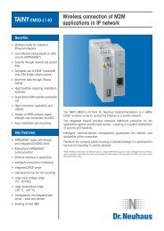
The SATEL I-LINK 100 or MINI-LINK<br />
I/O-converter and the SATELLINE-<br />
1870 radio modem are intended for<br />
setting up various short-range wireless<br />
monitor and control networks.<br />
Together they enable transferring I/O<br />
status, 4-20 mA or pulse information.<br />
These networks are best suited to<br />
environments where setting up cable<br />
connections would be either impossible<br />
or expensive.<br />
The SATELLINE-1870 is a lightweight<br />
and compact short-range radio modem,<br />
which operates on pan-European<br />
license-free frequencies. The radio<br />
modem is well suited to industrial<br />
data transfer solutions where connection<br />
distances are measured in<br />
hundreds of meters. In open environments,<br />
longer connection distances<br />
are possible. The SATEL I-LINK 100<br />
I/O-converter has four digital and<br />
two analog I/O-ports. MINI-LINK has<br />
two digital I/O-ports and fast pulse<br />
counter input.<br />
POINT-TO-POINT /<br />
POINT-TO-MULTIPOINT<br />
With two SATELLINE-1870 radio modems<br />
and SATEL I-LINK 100 or MINI-<br />
LINK converters, it is possible to setup<br />
a point-to-point connection. The easyto-use<br />
SATEL I-LINK PC Setting and<br />
Control Program enables the setup<br />
up of a wireless Point-to-Multipoint<br />
connection.<br />
M2M Point-to-Point package<br />
2 x SATELLINE-1870 radio modems<br />
2 x I-LINK 100 I/O converter<br />
2 x power supplies<br />
Cables, antennas<br />
User Guide<br />
M2M Point to Point Package<br />
YS0001<br />
M2M Multipoint package<br />
3 x SATELLINE-1870 radio modems<br />
2 x I-LINK 100 I/O converter<br />
3 x power supplies<br />
PC – software, cables, antennas<br />
User Guide<br />
M2M Point to MultiPoint Package<br />
YS0002<br />
MINI M2M package<br />
Similar to M2M packages, but<br />
includes MINI-LINK I/O-converters.<br />
Wireless MINI M2M package<br />
NEW: Modbus Compatibility<br />
MINI-LINK<br />
PULSE COUNTER AND I/O-CONVERTER<br />
FOR SATELLINE-1870.<br />
SATEL MINI-LINK is a compact, costeffective<br />
member of the SATELLINK<br />
product group of I/O converters. With<br />
the SATELLINE-1870 radio modem, it<br />
provides a handy tool for establishing<br />
wireless control and surveillance applications<br />
based on pulse counting and<br />
transfer of digital I/O-information.<br />
The MINI-LINK is a versatile converter,<br />
equipped with a pulse counter input and<br />
two digital inputs and outputs. It is connected<br />
directly to the SATELLINE-1870<br />
radio modem through an RS-232 serial<br />
interface. The pulse counter is used for<br />
online control of e.g. water, electricity,<br />
and gas consumption, while the digital<br />
ports are used to transfer the contact<br />
information of field instruments. The<br />
MINI-LINK is designed to receive pulse<br />
information in the Multipoint mode only,<br />
whereas I/O digital status information<br />
can be transferred in both Multipoint<br />
and Point-to-Point systems.<br />
SATEL MINI-LINK<br />
YI0090<br />
The MINI-LINK<br />
connects directly<br />
to the SATELLINE-870<br />
KEY FEATURES<br />
b 2 digital I/O-ports, solid<br />
state relays<br />
b Fast pulse counter input<br />
b Point-to-point or<br />
multipoint systems<br />
b Screw connectors to<br />
terminal<br />
b Small and cost effective<br />
b Ideal for remote<br />
controlling systems<br />
20
SATELLINK PC Pro<br />
EFFORTLESS CONTROL<br />
WITH RADIO MODEMS.<br />
With the SATELLINK PC Pro software<br />
you can monitor functions of the<br />
controls connected to the ports of<br />
the SATELLINK series I/O-converter.<br />
Using the Multipoint function, you<br />
can receive connector data, current<br />
loop values, pulses, set output states,<br />
adjust values and monitor radio links<br />
as well as perform other functions at<br />
a number of different substations.<br />
FUNCTIONALITY<br />
The external appearance of the user<br />
interface has been designed for easy,<br />
at-a-glance view of all functions. The<br />
function buttons and value fields can<br />
be renamed according to their userspecified<br />
functions. The analogue<br />
values can be set to show the value<br />
to be metered and the desired metering<br />
range. These functions are<br />
practical especially when others than<br />
the normal operator are using the<br />
system. Using the conversion feature,<br />
the analogue values can be changed<br />
to be digital when pre-defined alarm<br />
settings have been exceeded.<br />
SUPERVISION<br />
The supervision log was designed to<br />
facilitate user monitoring. It shows all<br />
functions that arise from a change in<br />
the settings. Based on the recorded<br />
data, a graphical presentation of<br />
information such as metering results<br />
and radio settings can easily be produced<br />
with the appropriate software.<br />
ROUTABLE<br />
Thanks to the routing feature, the<br />
digital or analogue inputs of the I/Oconverter<br />
can be routed as the output<br />
of any I/O-converter in the system.<br />
For example, in a group alarm one<br />
input can be set as the output of several<br />
substations simultaneously.<br />
COST-EFFECTIVE<br />
This cost-effective Multipoint software<br />
can be used to control several<br />
SATELLINK series I/O-converters and<br />
extension modules connected to<br />
SATELLINE radio modems. The maximum<br />
number of substations is 127<br />
pcs. At maximum, three extension<br />
modules can be connected to each<br />
basic unit if necessary.<br />
SATELLINK PC Pro<br />
ZA0001<br />
NEW FEATURES<br />
SATELLINK PC PRO NETWORK<br />
b Remote use through the WAN/<br />
LAN network<br />
b Several servers can be connected<br />
in the same system<br />
b Timed function settings<br />
b An alarm may be sent as an e-<br />
mail, which can be converted to<br />
an SMS message to the operator<br />
on duty<br />
b Routing from substation inputs to<br />
the outputs of another station/system<br />
b Routing through other modems in<br />
the system<br />
b Functions can be shown on top<br />
of user-selectable background image,<br />
such as a map<br />
b Automatic restarting after a<br />
power cut-off<br />
b Different products such as SATEL<br />
I-LINK 100, C-LINK 100 and<br />
MINI-LINK can be used in the<br />
same system<br />
b Automatic function control in a<br />
fault situation<br />
b Many user-friendly details<br />
b Analogue, digital, and pulse<br />
inputs/outputs<br />
<br />
<br />
<br />
<br />
<br />
<br />
<br />
21
A C C E S S O R I E S<br />
RS-LINK<br />
RS-232 TO RS-485/422<br />
SERIAL CONVERTER FOR<br />
THE SATELLINE-1870<br />
SATEL RS-LINK 100 is a cost-effective<br />
serial converter that can be configured<br />
to operate in compliance with<br />
RS-485 or RS-422. The galvanically<br />
isolated and surge suppression protected<br />
converter lines allow information<br />
exchange in full-duplex RS-422<br />
or half-duplex RS-485 mode. The<br />
RS-485 or RS-422 settings are easily<br />
selected by the DIP-switches. It is also<br />
possible to terminate the lines. The six<br />
LED indicators enable monitoring the<br />
system data transfer at a glance.<br />
SATEL-321<br />
Battery Pack<br />
Available for models 2ASc, 2ASxE,<br />
<strong>3AS</strong>(d), and <strong>3AS</strong>(d) 869, the<br />
SATEL-321 is beneficial when using<br />
radio modems in the field. The total<br />
weight of the splash-proof SATEL-<br />
321 package including the battery,<br />
charger, and radio modem is only<br />
1 kilogram. For easy carrying, the<br />
casing is equipped with a detachable<br />
shoulder strap. When used<br />
with the SATELLINE-<strong>3AS</strong>d, accessing<br />
the radio’s menu is possible since<br />
the buttons are extended through the<br />
casing.<br />
QUICK CHARGING<br />
The operating time of the modem<br />
(typically 8 - 10 hours) allows timeconsuming<br />
field jobs without recharging.<br />
SATEL offers both a standard<br />
charger and a car charger. The user<br />
can see at any time the remaining<br />
charge level of the battery, when used<br />
with the SATELLINE-<strong>3AS</strong>d.<br />
Complete Battery package SATEL-321 YP0321<br />
Data cable 321 / RS-485<br />
Data cable 321 / RS-232<br />
Charging cable 321<br />
AC adapter with charging cable 321<br />
Power cable 321<br />
YC0900<br />
YC0901<br />
YC0902<br />
YC0903<br />
YC0904<br />
Weather Proof<br />
Housing<br />
This accessory is a rugged, weatherproof<br />
housing for standard sized<br />
SATELLINE radios. Made of heavy<br />
duty ABS plastic, it comes complete<br />
with a cable interface kit and antenna<br />
coupling. Ideal for permanent applications,<br />
this kit can withstand the<br />
elements of water, sand, and time.<br />
Housing H-WP<br />
YI0001<br />
Weather Housing<br />
The unique design of this flexible,<br />
splash-proof weather housing offers<br />
the perfect solution for simple installations.<br />
Housing H-WPm2<br />
YI0004<br />
Other Power and<br />
Housing Products<br />
POWER SUPPLY<br />
230 Vac. 12 Vdc. 1 Amp.<br />
Power supply MAS-2<br />
YP0112<br />
230 Vac. 12 Vdc. 5 Amp. To be used<br />
with the SATELLINE <strong>3AS</strong>(d) Epic.<br />
Power supply MAS-4<br />
YP0601<br />
Power supply to install for DIN-rail.<br />
Power supply PS-DIN-1<br />
YP0117<br />
HOUSING<br />
Weatherproof housing for SATELLINE<br />
Epic models.<br />
Housing H-WP-X2<br />
YI0006<br />
22
C A B L E S<br />
CRS-2F. D15 male to D9 female. 2 meters. With Power Lead.<br />
RADIO MODEM CABLES<br />
INTERFACE<br />
ADAPTORS<br />
These interface adapters are equipped with a programming<br />
mode switch. The NARS-1F and NARS-1F-4A<br />
are primarily used for demo and configuration purposes.<br />
The adapter matches<br />
the lower connection<br />
on SATELLINE radio<br />
modems.<br />
NARS-1F. D15 male to D9 female. 650 mA fuse. YC0200<br />
RS-232 Interface. With 2 meter power supply cable<br />
NARS-1F-4A. Same as NARS-1F. With 4A fuse for Epic only. YC0204<br />
NARS-2.<br />
D15 male to screw connector. 650 mA fuse. YC0485<br />
Adaptor for RS-422 or RS-485 interface.<br />
NARS-2-4A. Same as NARS-2. With 4A fuse for Epic only. YC0486<br />
INTERFACE CABLES<br />
These cables connect radio modems to other terminal<br />
equipment. Each cable includes a 2 meter power supply<br />
cable. CRS-2F is pictured at the top of this page.<br />
CRS-1M. D15 male to D25 male. 2 meters. YC0101<br />
CRS-1F. D15 male to D25 female. 2 meters. YC0102<br />
CRS-2M. D15 male to D9 male. 2 meters. YC0103<br />
CRS-2F. D15 male to D9 female. 2 meters. YC0104<br />
CRS-18F. DIN4165-16 to D9 female. 1.5 meters YC0187<br />
Includes PROG and SHDN wires for 1870 modem.<br />
CRS-18IF. DIN4165-16 to D15 Female. 40 cm. Connects YC0190<br />
SATELLINE-1870 to I-LINK 100 or C-LINK 100.<br />
CRS-9, 2m. D9 - D9 female. 2 meters. No power cable.<br />
CRS-9, 1m. D9 - D9 female. 1 meters. No power cable.<br />
YC0201<br />
YC0202<br />
CRS-PB. For Profibus Interface. D15 - D9 male. 2 m. YC0501<br />
CRS-TSU D15 male to D15 female. Connects SATELLINE YC0271<br />
radio modems to I-LINK or C-LINK 100<br />
NARS-1F. D15 male to D9 female. With power lead.<br />
CRS-NMS 1.5 m cable D15 male to 2 x D9 female.<br />
From NMS master modem to user system and NMS PC.<br />
YC0302<br />
ANTENNA RF CABLES<br />
CRF-1 TNC male to TNC female. 1 meters. YC1101<br />
CRF-5F TNC male to TNC female. 5 meters. YC1105<br />
CRF-5M TNC male to TNC male. 5 meters. YC1106<br />
CRF-15<br />
TNC right-angle male to TNC female. 15 cm. YC1115<br />
CRF-1, SMA. SMA female to SMA male. 1 meter.<br />
For SATELLINE-1870 modems<br />
CRF-5,SMA SMA female to SMA male. 5 meters.<br />
For SATELLINE-1870 modems<br />
YC2101<br />
YC2105<br />
RG213 Low loss cable. 1.5dB / 10 meters. YC1000<br />
RG213 Connector TNC male to male.<br />
YC1002<br />
Aircom+ Low loss cable. 0.7dB / 10 meters. YC1001<br />
Aircom+ Connector. N male to N male.<br />
Includes N female to TNC male adaptor.<br />
Set includes two N connectors and one adaptor.<br />
INSTALLATION PARTS FOR DIN-RAIL<br />
DIN-1 96 x 70 mm ME0205<br />
DIN-2 67 x 70 mm ME0210<br />
DIN For Epic ME0213<br />
YC1003<br />
ADDITIONAL CABLES<br />
ESERV-10S Null Modem Cable for ESERV-10S YC0700<br />
and IP-LINK<br />
CRS-IPT 2 m test cable D15 female to D15 female YC0402<br />
between IP-LINKs.<br />
321 CABLES<br />
Accessory cables used with the 321 Battery Pack.<br />
Data cable 321 / 485<br />
YC0900<br />
Data cable 321 / 232<br />
Charging cable 321<br />
AC adapter with charging cable 321<br />
Mains Power cable 321<br />
YC0901<br />
YC0902<br />
YC0903<br />
YC0904<br />
23
A N T E N N A S<br />
1<br />
OMNI DIRECTIONAL<br />
ANTENNAS<br />
The following portable omni-directional<br />
antennas are offered directly by SATEL.<br />
Our distributors offer other specialized<br />
antennas, like offset pattern and directional<br />
antennas. Contact your distributor<br />
for a complete antenna listing.<br />
1 GAINFLEX ANTENNAS<br />
Half Wave whip antenna. Flexible,<br />
highly elastic antenna. Attach<br />
directly to modem or with cable to<br />
ground plane.<br />
Frequencies<br />
Distance<br />
Connection<br />
400 ... 435 MHz<br />
435 ... 470 MHz<br />
±3 km<br />
TNC, 50 Ω, male<br />
4 ANTENNA 869<br />
For use with the SATELLINE-<strong>3AS</strong><br />
869. Quarter Wave whip antenna.<br />
Attach directly to modem or with<br />
cable to ground plane.<br />
Frequency<br />
Distance<br />
Connection<br />
Length<br />
Weight<br />
869 MHz<br />
±1 km<br />
TNC, 50 Ω, male<br />
69 mm<br />
35 g<br />
Length<br />
Weight<br />
420 mm<br />
40 g<br />
Antenna Gainflex 400-435 MHz<br />
Antenna Gainflex 435-470 MHz<br />
YA0106<br />
YA0103<br />
3 MULTIFLEX ANTENNA<br />
Quarter Wave whip antenna. Flexible,<br />
highly elastic antenna. Attach<br />
directly to modem or with cable to<br />
ground plane.<br />
Antenna 869<br />
YA0869<br />
Frequency<br />
Distance<br />
400 ... 470 MHz<br />
±1 km<br />
2<br />
3<br />
2 ANTENNA 1870<br />
For use with the SATELLINE-1870.<br />
Attach directly to modem or with<br />
cable to ground plane.<br />
Frequency<br />
Distance<br />
Connection<br />
Length<br />
Weight<br />
Antenna 1870<br />
868 ... 870 MHz<br />
±2 km<br />
SMA, 50 Ω, male<br />
169 mm<br />
35 g<br />
YA1869<br />
Connection<br />
Length<br />
Weight<br />
TNC, 50 Ω, male<br />
165 mm<br />
35 g<br />
Antenna Multiflex 400-470 MHz<br />
YA0101<br />
5 MINIFLEX ANTENNAS<br />
Extra short, highly elastic antenna.<br />
Attach directly to modem.<br />
Frequencies<br />
Distance<br />
400 ... 435 MHz<br />
435 ... 470 MHz<br />
± 1 km<br />
Connection<br />
TNC, 50 ohm, male<br />
Length<br />
67 mm<br />
Weight<br />
18 g<br />
Antenna Miniflex 400-435 MHz<br />
Antenna Miniflex 435-470 MHz<br />
YA0104<br />
YA0102<br />
4<br />
5<br />
24
A N T E N N A S E L E C T I O N<br />
HOW TO SELECT<br />
YOUR ANTENNA<br />
With proper antenna selection, the<br />
overall performance of a radio network<br />
can be significantly improved.<br />
Proper antenna configuration makes<br />
a network more controlled, closed,<br />
and tolerant to possible interference.<br />
ANTENNA TYPES<br />
There are three types of antennas<br />
distinguished by radiation characteristics:<br />
omni-directional antennas, offset-pattern<br />
antennas and directional<br />
antennas. The usage of different<br />
antenna types is highly dependent<br />
on the shape and nature of the radio<br />
network: point to point, point to<br />
multipoint, number of base stations,<br />
fixed or mobile substations, possible<br />
repeaters, diversity reception, etc.<br />
POINT TO POINT NETWORKS<br />
In point to point, fixed radio networks,<br />
it is always highly recommended<br />
to use directional antennas<br />
(see diagram for CAY, CAY+,<br />
CAY++, CAY+++, CAY++++) when<br />
applicable. This is because of better<br />
control over the system and closed<br />
construction: the signal is forced<br />
and noise collected only to and from<br />
the relevant directions. This also<br />
minimizes the total amount of radio<br />
interference in general.<br />
POINT TO MULTIPOINT<br />
NETWORKS<br />
In point to multipoint radio networks,<br />
one or multiple base stations are<br />
serving multiple substations—fixed<br />
or mobile. Typically, base stations<br />
are equipped with omni-directional<br />
(CAE2, CAE4, CAGP, CAGP+) or offset<br />
pattern antennas (CAC2, CAC4)<br />
in order to serve substations inside a<br />
big angle. Usually, the system layout<br />
is not symmetrical nor is the base station<br />
in the symmetrical center point.<br />
In these cases, the offset pattern base<br />
station antenna is the best choice.<br />
If all the substations are within a<br />
small angle, the directional base<br />
station antenna is recommended for<br />
the reasons mentioned above. The<br />
fixed substations should always be<br />
equipped with directional antennas.<br />
The mobile substations usually have<br />
to be equipped with omni-directional<br />
antennas.<br />
REPEATER STATIONS<br />
When using repeaters, transparent of<br />
buffering, each repeater output has<br />
to be considered as a base station<br />
for its own subsystem and the corresponding<br />
antennas chosen accordingly<br />
for both the base station and<br />
substations.<br />
DIVERSITY (DUAL)<br />
ANTENNAS<br />
In space diversity applications, dual<br />
antennas, chosen as mentioned<br />
above, they are used and located<br />
physically separated on a vertical<br />
or horizontal axis. In polarization<br />
diversity, the special cross-polarized<br />
antennas (CAX, CAX+, CAX++) can<br />
be used. Multiple antennas can also<br />
be combined to form arrays in order<br />
to find more gain and radiation pattern<br />
combinations to meet the requirements.<br />
The antennas are combined<br />
with power splitters (CS) to maintain<br />
the impedance match. When mounting<br />
the antennas at high locations, it<br />
is also recommended to use separate<br />
lightning protectors (LP) to ensure the<br />
radio modem against lightning striking<br />
the antenna, mast or surroundings.<br />
25
N E T W O R K D E S I G N C E N T E R<br />
Our network design<br />
center wants to help<br />
you create a troublefree<br />
wireless data<br />
transfer network.<br />
In case you are not familiar in using<br />
wireless radio data modems or if<br />
your system is complicated and you<br />
are not sure how to design the network,<br />
please feel free to contact us.<br />
However small your system might be,<br />
it is big enough for us! The quickest<br />
way of getting support is to contact a<br />
distributor in your own country. They<br />
are able to communicate with you<br />
in your own language and they are<br />
also close by. However, if they do<br />
not have the resources or application<br />
specific know-how, we are prepared<br />
to assist them and you as well. Please<br />
feel free to contact our Netwrok Design<br />
Center at ndc@satel.com<br />
Having been in this business over<br />
twenty years, we are happy to share<br />
our experience with you in designing<br />
your radio network.<br />
This service could include the following<br />
(all or only a part depending on your<br />
case):<br />
b A budgetary price to start so you<br />
can estimate the overall expenses<br />
for your project. This would be<br />
based on the description of your<br />
system.<br />
b Propagation measurements on site<br />
to ensure that the system will work<br />
properly<br />
b Actual design of the network based<br />
on the measurements<br />
b Binding offer for the entire radio<br />
network including the radios,<br />
antennas with cables, data cables,<br />
connectors needed, etc.<br />
b Delivery of the high quality products<br />
in a short time thanks to our<br />
own production<br />
b Installation of the radio network as<br />
an option together with our local<br />
distributor<br />
b Testing of the system after installation,<br />
including training of your staff<br />
b Handing over of the network to you<br />
b Guarantee<br />
26
P L A N N I N G A N E T W O R K<br />
PLAN NETWORK REQUIREMENTS<br />
Like other engineering tasks, design<br />
of a radio modem network requires<br />
a set of rules to be followed for producing<br />
the desired result. Both the<br />
radio connections themselves and<br />
the compatibility of the surrounding<br />
system need to be considered.<br />
The first part of the design is to<br />
evaluate the requirements the system<br />
environment, geography, and the<br />
local radio frequency and transmission<br />
laws.<br />
SYSTEM ENVIRONMENT<br />
• Data protocol<br />
• Interface types<br />
• Maximum response times<br />
GEOGRAPHY<br />
• Station locations<br />
• Topographic profiles<br />
• Buildings or other obstacles<br />
LOCAL RADIO TRANSMISSION<br />
REGULATIONS (AUTHORITIES)<br />
• Available radio channels<br />
• Max. Radiated power<br />
• Tx/Rx duty cycle<br />
PLAN NETWORK HARDWARE<br />
With the desired system performance<br />
and the limitations above in<br />
mind, the first version of the radio<br />
modem network can be designed:<br />
1. Radio modem types and serial<br />
cable wirings are specified.<br />
2. Radio links are simulated giving<br />
the antenna types and heights,<br />
feed cable lengths, and whether<br />
any additional repeater stations<br />
will be needed.<br />
3. If necessary, other system components<br />
like RF filters, RF relays,<br />
combiners, lightning protectors,<br />
power supplies, and installation<br />
parts are specified.<br />
4. Data transmission delays are calculated<br />
for the sufficient number<br />
of RF channels.<br />
After these four steps, the system<br />
design is typically detailed enough<br />
for a commercial quotation.<br />
TEST THE COMPONENTS BEFORE<br />
FINAL INSTALLATION<br />
Data communication tests at the factory,<br />
radio signal propagation, and<br />
radio interference tests on the field<br />
are important. The tests verify the<br />
functionality of the designed system,<br />
compatibility to the surrounding<br />
system, and the correct settings of<br />
the devices. Proper signal-to-interference<br />
margin is essential for reliable<br />
error-free radio communications.<br />
REPEAT TESTS AFTER<br />
FINAL INSTALLATION<br />
By repeating the communication<br />
tests after the final installations, the<br />
system designer may verify that the<br />
radio network design works with the<br />
desired application.<br />
27
AUSTRALIA<br />
Rojone PTY Limited<br />
61 Aero Rd<br />
Ingleburn<br />
NSW 2565 SYDNEY<br />
tel: +61 02 9829 1555<br />
sales@rojone.com.au<br />
www.rojone.com.au<br />
AUSTRIA<br />
SATEL Radio Modems AUSTRIA<br />
Mariahilfer Strasse 123/3<br />
AT-1060 VIENNA<br />
tel: +43 1 59999 770<br />
info@satelaustria.com<br />
www.satelaustria.com<br />
BELGIUM<br />
SKYLINE COMMUNICATIONS N.V.<br />
Zandstraat 14<br />
BE-8870 IZEGEM<br />
tel: +32 51 313 569<br />
info@skyline.be<br />
www.skyline.be<br />
BULGARIA<br />
CONTROL SYSTEM Bulgaria<br />
EOOD<br />
37, Graf Ignatiev Str., fl.2<br />
1000 SOFIA<br />
tel: +359 2 984 8355<br />
info@controlsystem.bg<br />
www.controlsystem.gr<br />
CANADA<br />
MDA Controls Inc.<br />
1131 Invicta Drive, Unit 4<br />
OAKVILLE, ON L6H 4M1<br />
CANADA<br />
tel: +1 905 845 3666<br />
joe.altman@mdacontrols.com<br />
www.mdacontrols.com<br />
CENTRAL-AMERICA,<br />
CARIBBEAN<br />
SATEL CARIBE CORP<br />
7625 NW 54th Street<br />
MIAMI, FL 33166<br />
tel: +1 305 592 0593<br />
sales@satelcaribe.com<br />
www.satelcaribe.com<br />
<strong>Satel</strong> Caribe Corp serves Antigua, Aruba, Bahamas, Barbados,<br />
Bermuda, Bonaire, British West Indies, Cayman Islands,<br />
Curaçao, Dominica, Dominican Rebuplic, Grenada, Haiti,<br />
Jamaica, Netherlands Antilles, Puerto Rico, St. Maarten, St.<br />
Lucia, St. Vincent, Trinidad/Tobaco, Turks and Caicos, US<br />
Virgin Islands, Belize Costa Rica, El Salvador, Guatemala,<br />
Honduras, Nicaragua and Panama<br />
CHINA P.R.<br />
Guangzhou Chuang Li Instrument<br />
Comp.<br />
Building A, 355#<br />
Middle of Guangzhou Avenue<br />
GUANGZHOU<br />
Tel: +86 20 8736 4093<br />
E-map@163.net<br />
www.clyq.com<br />
CROATIA<br />
MICRO-LINK d.o.o.<br />
Franje Fuisa 12<br />
HR-10000 ZAGREB<br />
tel: +385 1 363 6884<br />
microlink@microlink.hr<br />
www.microlink.hr<br />
MICRO-LINK d.o.o serves Croatia and Bosnia and<br />
Herzegovina<br />
CZECH REPUBLIC<br />
ControlTech s.r.o.<br />
Havlíckova 822<br />
CZ-280 00 KOLÌN<br />
tel: +420 321 7420 11<br />
info@controltech.cz<br />
www.controltech.cz<br />
DENMARK<br />
COMSYSTEM A/S<br />
Porthusvej 9 B<br />
DK-3490 KVISTGAARD<br />
tel: +45 49 139 693<br />
salg@comsystem.dk<br />
www.comsystem.dk<br />
ESTONIA<br />
ALARMTEC AS<br />
Saku 15<br />
EE-11314 TALLINN<br />
tel: +372 6 598 800<br />
alarmtec@alarmtec.ee<br />
www.alarmtec.ee<br />
FINLAND<br />
SATEL Oy<br />
P.O.Box 142<br />
FI-24101 SALO<br />
tel: +358 2 777 7800<br />
info@satel.com<br />
www.satel.com<br />
FRANCE<br />
COMATIS<br />
8 parc Ariane<br />
Immeuble Jupiter<br />
2 rue Hélène Boucher<br />
FR-78284 GUYANCOURT<br />
tel: +33 1 3930 2900<br />
info@comatis.com<br />
www.comatis.com<br />
GERMANY<br />
SATEL Deutschland GmbH & Co.<br />
KG<br />
Holstenhofweg 11<br />
DE-22041 HAMBURG<br />
tel: +49 40 4840 1930<br />
anfragen@satel-deutschland.de<br />
www.satel-deutschland.de<br />
GREECE<br />
CONTROL SYSTEM Ltd.<br />
13, Chlois Str.<br />
GR-54627 THESSALONIKI<br />
tel: +302 310 521 055<br />
info@controlsystem.gr<br />
www.controlsystem.gr<br />
HUNGARY<br />
ControlTech s.r.o.<br />
Távíró köz 4.<br />
HU-2040 BUDAÖRS<br />
tel: +36 23 445 900<br />
info@controltechhungary.hu<br />
www.controltechhungary.hu<br />
ICELAND<br />
Naust Marine hf<br />
Skeidarasi 3<br />
IS-210 GARDABÆ<br />
tel: +354 565 8080<br />
thp@naust.is<br />
www.naust.is<br />
INDIA<br />
LOTUS WIRELESS<br />
B-7, E-E Industrial Development<br />
Area<br />
B-Block, Autonagar<br />
IN-530012 VISAKHAPATNAM<br />
tel: +91 891 276 1678<br />
info@lotuswireless.com<br />
www.lotuswireless.com<br />
V. AUTOMAT & INSTRUMENTS<br />
(P) LTD.<br />
F-61, Okhla Industrial Area<br />
Phase-I<br />
IN-110020 NEW DELHI<br />
tel: +91 11 2681 0307<br />
vautomat@vsnl.com<br />
www.vautomatindia.com<br />
ISRAEL<br />
Arrowmid Group Ltd<br />
108 Yigal Alon st<br />
IL-67891 TEL AVIV<br />
tel: +972 36 247 080<br />
info@arrowmid.com<br />
www.arrowmid.com<br />
ITALY<br />
SARTELCO SISTEMI S.r.l.<br />
Quartiere Torri Bianche 1<br />
Palazzo Sequoia - 10° piano<br />
IT-20059 VIMERCATE (MI)<br />
tel: +39 039 629 051<br />
info@sartelco.it<br />
www.sartelco.com<br />
KAZAKHSTAN<br />
Automation & Technologies Ltd.<br />
Satpaev St., 90, office 10<br />
ALMATY<br />
tel: +7 3272 598 359<br />
office@automation.kz<br />
wwww.automation.kz<br />
KOREA<br />
Thomas Trading Co. Ltd.<br />
431-716 #Techno Town C-3201,<br />
#889-1<br />
Kwan Yang 2-Dong<br />
Anyang-Si<br />
KYUNG GI-DO<br />
tel: +82 31 424 3030<br />
aunny@thomas.co.kr<br />
www.thomas.co.kr<br />
LATIN AMERICA<br />
SATEL-West in US serves Latin America<br />
LATVIA<br />
ALARMTEC AS in Estonia serves Latvia<br />
LITHUANIA<br />
ALARMTEC AS in Estonia serves Lithuania<br />
MALAYSIA<br />
DIGISELECT Pte Ltd in Singapore serves Malaysia<br />
MIDDLE EAST<br />
SATEL MIDDLE EAST Ltd.<br />
Katrineholminkatu 6 as 17<br />
FI-24100 SALO, FINLAND<br />
tel: +358 40 821 4318<br />
info@sardame.com<br />
www.sardame.com<br />
SATEL MIDDLE EAST Ltd. or their dealers serves Libya, Oman,<br />
Syria, Jordan, Lebanon, Iran, Iraq, UAE, Bahrain, Qatar,<br />
Kuwait and Yemen.<br />
NORTHERN AFRICA<br />
COMATIS in France serves the following Northern African<br />
countries: Algeria, Cameroun, Congo, Democratic Republic<br />
of Congo, Center African Republic, Benin, Burkina Fasso,<br />
Ivory Cost, Guinea, Mali, Marocco, Nigeria, Senegal, Tchad,<br />
Togo and Tunisia<br />
NORWAY<br />
SATEL NORGE AS<br />
Hoydaveien 17<br />
NO-1523 MOSS<br />
tel: +47 69 27 70 40<br />
produktinfo@satel.no<br />
www.satel.no<br />
POLAND<br />
ASTOR sp. z o.o. (Main Branch)<br />
Ul. Smolensk 29<br />
PL-31112 KRAKOW<br />
tel: +48 12 428 6300<br />
satel@astor.com.pl<br />
www.astor.com.pl<br />
PORTUGAL<br />
AEROSISTEMAS -Sosiedade de<br />
Importacâo e Exportacâo Lda<br />
Rua de S. Bernardo 108 3<br />
PT-1200 LISBON<br />
tel: +351 21 414 2362<br />
aerosistemas@hotmail.com<br />
www.aerosistemas.net<br />
ROMANIA<br />
SC TA. EL IMPEX SRL<br />
str Sergent Latea<br />
Gheorghe nr.13<br />
bl C70, sc.2, ap 75, sector 6<br />
BUCHAREST<br />
tel: + 4 021 424 6266<br />
tael@digi.ro<br />
www.tael.ro<br />
RUSSIA<br />
SATEL-ROSS ltd.<br />
2-Zvenigorodskaja Str,<br />
13/41. Business Center<br />
123022 MOSCOW<br />
tel: +7 095 234 5846<br />
info@satel-ross.com<br />
www.satel-ross.com<br />
SINGAPORE<br />
DIGISELECT Pte Ltd<br />
371 Beach Road<br />
# 07-04 Keypoint<br />
SG-199597 SINGAPORE<br />
tel: +65 968 23238<br />
dgselect@cyberway.com.sg<br />
www.digiselect.com<br />
SLOVAK REPUBLIC<br />
ControlTech s.r.o.<br />
Frantiskánska 5<br />
SK-917 00 TRNAVA<br />
tel: +421 33 591 3811<br />
info@controltech.sk<br />
www.controltech.sk<br />
SLOVENIA<br />
METRONIK d.o.o<br />
Stegne 9A<br />
SI-1000 LJUBLJANA<br />
tel: +386 1 514 0800<br />
info@metronik.si<br />
www.metronik.si<br />
METRONIK d.o.o serves Slovenia and Serbia and<br />
Montenegro<br />
SOUTH AFRICA<br />
SATEL SA<br />
51 Brunton Circle<br />
Founders View South<br />
Modderfontein<br />
1645 GAUTENG<br />
tel: +27 11 201 3200<br />
mark@satelsa.co.za<br />
www.i8a8.co.za/<br />
SPAIN<br />
SATEL SPAIN S.L.<br />
Avda de España 135,<br />
Bloque 2A, 1° 2<br />
ES-28230 LAS ROZAS, MADRID<br />
tel: +34 91 636 22 81<br />
info@satelspain.com<br />
www.satelspain.com<br />
SWEDEN<br />
PRO4WIRELESS<br />
Fredrik Jahns Grand 1<br />
SE-13136 NACKA<br />
tel: +46 8 718 1700<br />
info@pro4wireless.com<br />
www.pro4wireless.com<br />
SWITZERLAND<br />
LINK COMPUTER SERVICES s.a.<br />
Chemin des Rosiers 9<br />
CH-1763 GRANGES-PACCOT/FR<br />
tel: +41 26 469 0700<br />
linkcomputer@datacomm.ch<br />
TAIWAN<br />
ENVIRONMENTAL SCIENCE &<br />
ENG’N CORP.<br />
14F, No. 31, Sec.2 San Min Rd.<br />
Pan Chiao City, TAIPEI HSIEN<br />
tel: +886 2 2963 4300<br />
sales@esne.com.tw<br />
www.esne.com.tw<br />
THE NETHERLANDS<br />
NAUTIKARIS b.v.<br />
Broekbergenlaan 48<br />
NL-2071 EW SANTPOORT-<br />
NOORD<br />
tel: +31 23 538 9502<br />
info@nautikaris.com<br />
www.nautikaris.com<br />
TURKEY<br />
BILKO AS<br />
Perpa Ticaret Merkezi<br />
B-Blok Kat 11 No:1740<br />
TR-80270 OKMEYDANI,<br />
ISTANBUL<br />
tel: +90 212 320 1383<br />
bilko@bilko-automation.com<br />
www.bilko-automation.com<br />
UKRAINE<br />
CJSC New Technologies<br />
2-A, Novokonstantinovskaya str.<br />
04080 KIEV<br />
tel: +380 44 451 4365<br />
office@ntech.kiev.ua<br />
www.ntech.kiev.ua<br />
UNITED KINGDOM<br />
XL SYSTEMS Ltd<br />
XL House<br />
Leas Road<br />
Warlingham<br />
Surrey CR6 9LN<br />
tel: +44 1883 622 778<br />
sales@xls.co.uk<br />
www.xls.co.uk<br />
UNITED STATES<br />
SATEL North America L.L.C<br />
200 Spangler Ave.<br />
ELMHURST, IL 60126<br />
tel: toll free in the US for sales:<br />
+1 800 292 9778,<br />
for service + 1 800 776 7706<br />
satelservice@chicomm.com<br />
www.satelnorthamerica.com<br />
SATEL’s Offically Approved US Service Office. Contact for<br />
your service, technical support and sales needs excluding<br />
the west coast.<br />
SATEL-West<br />
10680 S.DeAnza Blvd. #D<br />
CUPERTINO, CA 95014<br />
tel: +1 800 915 1109<br />
info@satel-west.com<br />
www.satel-west.com<br />
SATEL-West is serving CA, OR, AZ, WA states in the USA and<br />
serving Latin America.<br />
Tin Can Technologies<br />
2230 N. University PKWY, STE 7E<br />
Provo, UT 84604<br />
tel: +1 801 356 1924<br />
sales@tincantech.com<br />
www.tincantech.com<br />
Serving your land survey needs only<br />
VIETNAM<br />
TRIEUHA Co. Ltd<br />
Suite 1505, 17T5 Tower<br />
New Urban Area<br />
Trunghoa-Nhanchinh<br />
HANOI<br />
tel: +84 4 251 0400<br />
info@trieuha.com<br />
www.trieuha.com<br />
28<br />
SATEL Oy, Meriniitynkatu 17, P.O. Box 142, FI-24101, SALO, FINLAND<br />
Tel: +358 2 777 7800, Fax: +358 2 777 7810 E-mail: info@satel.com<br />
www.satel.com