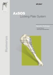
AxSOS Extremity Plating System Operative Technique - Stryker
AxSOS Extremity Plating System Operative Technique - Stryker
AxSOS Extremity Plating System Operative Technique - Stryker
You also want an ePaper? Increase the reach of your titles
YUMPU automatically turns print PDFs into web optimized ePapers that Google loves.
<strong>Operative</strong> <strong>Technique</strong><br />
Asnis III 4.0mm<br />
The Asnis III Cannulated Screw<br />
<strong>System</strong> is intended for fracture<br />
fixation of small and long bones<br />
and of the pelvis. The system is<br />
not intended for spinal use.<br />
Step One: Insert Guide Wire<br />
Using the ø1.4/2.7mm double drill<br />
guide, insert a ø1.4 x 150mm Guide<br />
Wire to the appropriate depth.<br />
Use image intensification to control<br />
reduction and Guide Wire placement.<br />
Place additional guide wires as<br />
necessary. Remove the double<br />
drill guide.<br />
Note:<br />
In dense bone, puncturing the<br />
cortex with the ø1.4 x 150mm drill<br />
bit to initiate the wire may reduce<br />
heat build-up and/or deflection of<br />
the wire.<br />
Alternative: Substitute the ø1.4 x<br />
150mm Guide Wire with a ø1.4 x<br />
150mm drill bit. Throughout the<br />
procedure it is possible to interchange<br />
the Guide Wire and drill bit.<br />
Option:<br />
A parallel drill guide is available for<br />
parallel placement of Guide Wire.<br />
Optional: Countersink or Washer?<br />
Where soft tissue coverage is minimal,<br />
use of the countersink to further recess<br />
the low profile screw head may be<br />
beneficial.<br />
In bone where the cortex is thin,<br />
washers can be applied to spread the<br />
load of the screw head over a greater<br />
area.<br />
Note:<br />
The countersink design does not<br />
require pre-drilling.<br />
Step 2: Measure for Screw Length<br />
Slide the direct measuring gauge over<br />
the ø1.4 x 150mm Guide Wire. The<br />
direct measuring gauge measures direct<br />
to the tip of the Guide Wire. This allows<br />
the final screw position to correspond<br />
with the initial tip position of the<br />
Guide Wire.<br />
Select appropriate screw length. Length<br />
adjustment is particularly important<br />
if the tip is near an articular surface.<br />
Note:<br />
Care should be taken to ensure<br />
the direct measuring gauge tip<br />
engages the bone when a reading<br />
is taken.<br />
Step 3: Insert Screw<br />
Using the cannulated screwdriver with<br />
Elastosil® handle and the screw holding<br />
sleeve, insert the selected screw over the<br />
Guide Wire. Release the screw holding<br />
sleeve prior to final tightening.<br />
Remove screwdriver and screw<br />
holding sleeve.<br />
Note:<br />
The thread of the Asnis screw is<br />
designed for insertion in cancellous<br />
bone. If it used in cortical bone<br />
tapping is required prior to screw<br />
insertion.<br />
Always verify both Guide Wire<br />
and screw position with periodic<br />
image intensification.<br />
Step 3: Verify Final Reduction<br />
Verify the final position of the screw.<br />
Remove and discard the Guide Wire.<br />
Repeat as necessary for additional<br />
screws.<br />
16


