For servo motor - Romani Components
For servo motor - Romani Components
For servo motor - Romani Components

You also want an ePaper? Increase the reach of your titles
YUMPU automatically turns print PDFs into web optimized ePapers that Google loves.
Index<br />
<br />
<br />
<br />
<br />
<br />
<br />
<br />
<br />
<br />
<br />
<br />
<br />
<br />
<br />
VR<br />
1~100<br />
<br />
<br />
<br />
<br />
<br />
<br />
<br />
<br />
<br />
EF<br />
1~44
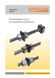
<strong>For</strong> <strong>servo</strong> <strong>motor</strong><br />
ABLE Reducer<br />
どんなところに 使 われれていますか?<br />
Series & Use<br />
Fully-featured, durable, and highly precise Able reducer keeps<br />
increasing its series to meet ever changing automation needs.<br />
Coaxial shaft<br />
VRL series<br />
High rigidity type<br />
NEW<br />
Compact but yet powerful<br />
(for cutting and welding machines etc)<br />
Page<br />
VR3<br />
Coaxial shaft<br />
VRS series<br />
High rigidity type<br />
NEW<br />
Generating highly precise and powerful<br />
torque.(for printing machine etc)<br />
Page<br />
VR8<br />
Coaxial shaft<br />
VRSF series<br />
Standard type<br />
Page<br />
VR13<br />
Recommended to customers requiring<br />
lightweight and space saving, e.g. gantry,<br />
packing machine, etc.<br />
Coaxial shaft<br />
VRHF series<br />
Long life and high capacity type<br />
Page<br />
VR49<br />
R e c o m m e n d e d t o c u s t o m e r s<br />
requiring large torque(torque, rotary<br />
power) and long life, e.g.press,<br />
molding machine, etc.<br />
Coaxial shaft<br />
VRSF-A series<br />
Compact type<br />
Page<br />
VR57<br />
Recommended to customers who consider<br />
compact and light weight devices or equipment<br />
1<br />
VR
INDEX<br />
Coaxial shaft<br />
VRG series<br />
High precision type<br />
Page<br />
VR59<br />
Recommended to customers requiring high<br />
precision of semiconductor manufacturing<br />
system, machine tools, etc.<br />
Right angle shaft<br />
NEV series<br />
Standard type<br />
Page<br />
VR83<br />
Recommended to customers<br />
who try to reduce length of a<br />
reducer, e.g. conveyor.<br />
Right angle shaft<br />
EVRG series<br />
High precision type<br />
Page<br />
VR93<br />
Recommended to customers who<br />
try to reduce length of a reducer,<br />
e.g. conveyor, and at the same<br />
time gain high precision.<br />
Hollow shaft<br />
STH<br />
Hollow type<br />
series<br />
NEW<br />
Page<br />
VR99<br />
Minimizing space by letting cables<br />
and shaft go through. (for turn table<br />
applications etc)<br />
VR 2
Coaxial shaft<br />
VRL/VRS<br />
series<br />
Features<br />
VR<br />
ABLE REDUCER<br />
EF<br />
CORONET REDUCER FOR SERVO MOTOR<br />
VRS<br />
VRL<br />
VRS<br />
VRL<br />
series<br />
Quiet operation<br />
Helical gear contribute to reduce vibration and noise.<br />
“Noiseless” and “Firm Body”<br />
Firm Body<br />
Internal teeth are machined to the steel body directly to produce high output<br />
torque.<br />
Long Service Life<br />
The high-class grease in ABLE reducer gives permanent lubrication. No<br />
need to replace the grease for the life time (20,000 hours).<br />
Easy mounting<br />
Motor can be mounted easily with adapter flange and bushing (without key).<br />
Applicable to each brand's <strong>servo</strong><strong>motor</strong>s.<br />
Variety of Ratios<br />
We can offer the fourteen ratios and anaible from 1/3 to 1/100.<br />
VRL<br />
3<br />
VR
Features<br />
Coaxial shaft<br />
VRL/VRS<br />
series<br />
Automatic Labor Saving Machine<br />
Medical Machinery<br />
VR<br />
ABLE REDUCER<br />
Extruders<br />
Automatic Labor Saving Machine<br />
EF<br />
CORONET REDUCER FOR SERVO MOTOR<br />
VRS series<br />
Quiet operation<br />
Helical gear contribute to reduce vibration and noise.<br />
High precision<br />
Standard backlash is 3 arc-min,ideal for precision control.<br />
High rigidity<br />
Employing taper roller bearing for the main output shaft to increase radial and axiol load.<br />
Long Service Life<br />
The high-class grease in ABLE reducer gives permanent lubrication. No<br />
need to replace the grease for the life time (20,000 hours).<br />
Easy mounting<br />
Motor can be mounted easily with adapter flange and bushing (without key).<br />
Applicable to each brand's <strong>servo</strong><strong>motor</strong>s.<br />
“Hight precision” and “Hight rigidity”<br />
VRS<br />
VR 4
Coaxial shaft<br />
VRL series<br />
MODEL NUMBER CHART<br />
“Noiseless” and “Firm Body”<br />
VR<br />
ABLE REDUCER<br />
■Model Number Chart<br />
ABLE reducer<br />
VR L 090 7 K<br />
Servo Motor<br />
5 19HB16<br />
EF<br />
CORONET REDUCER FOR SERVO MOTOR<br />
Best-In-Class Standard<br />
Backlash 5 arc-min<br />
K:Shaft with keyway<br />
Ratio:<br />
1/3、4、5、7、10(Single Reduction)<br />
1/15、20、25、30、35、40、50、70、100(Double Reduction)<br />
Frame Size:050、070、090、120<br />
VRLseries<br />
Model Name for ABLE reducer<br />
Mount code varies depending on the <strong>motor</strong><br />
Adapter:The flange-shaped component for installing the <strong>servo</strong><strong>motor</strong> to the gear reducer.<br />
Bushing:In case the diameters of the output shaft of the <strong>servo</strong><strong>motor</strong> and the input<br />
shaft of the gear reducer have different dimensions, this component can be inserted<br />
into the input shaft of the gear reducer as for the figure below. This makes the<br />
reducer’s input shaft diameter to be equal to the output shaft of the <strong>servo</strong><strong>motor</strong>.<br />
Example: Mount code<br />
19 HB 16<br />
Output Shaft Diameter of the Servo<strong>motor</strong><br />
※Adapter Code:Refer to the P.8 “Instruction of the Servo<br />
Reducer<br />
Selection Tool”.:<br />
※Please consult us for other Adapter Code if necessary.<br />
Bore Dimension of the Input Shaft of the Gear Reducer: 8, 14, 19, 28, 38, 45, & 65<br />
Note: The φ16 bushing needs to be inserted into the input shaft of the gear<br />
reducer for the above case.<br />
■Image of the Bushing<br />
Servo<strong>motor</strong> サーボモータシャフト Shaft<br />
Input Shaft of Gear Reducer<br />
Bushing<br />
5<br />
VR
SPECIFICATIONS<br />
Coaxial shaft<br />
VRL series<br />
■VRL Series Specifications<br />
Frame<br />
Size<br />
050<br />
070<br />
090<br />
120<br />
Stages Ratio<br />
※1<br />
Nominal<br />
Output<br />
Torque<br />
[Nm]<br />
※2<br />
Maximum<br />
Output<br />
Torque<br />
[Nm]<br />
※3<br />
Emergency<br />
Stop<br />
Torque<br />
[Nm]<br />
※4<br />
Nominal<br />
Input<br />
Speed<br />
[rpm]<br />
※5<br />
Maximum<br />
Input<br />
Speed<br />
[rpm]<br />
※6<br />
Permitted<br />
radial load<br />
[N]<br />
※7<br />
Maximum<br />
radial load<br />
[N]<br />
※8<br />
Permitted<br />
axial load<br />
3 7 14 28 4000 8000 410<br />
350<br />
4 7.5 15 30 4000 8000 440 390<br />
Single 5 7.5 15 30 4000 8000 470 420<br />
7 7.5 15 30 4000 8000 520 480<br />
10 7 14 28 4000 8000 590 560<br />
15 7 14 28 4000 8000 670 680<br />
20 7.5 15 30 4000 8000 700 700<br />
700<br />
25 7.5 15 30 4000 8000 700 700<br />
30 7 14 28 4000 8000 700 700<br />
Double 35 7.5 15 30 4000 8000 700 700<br />
40 7.5 15 30 4000 8000 700 700<br />
50 7.5 15 30 4000 8000 700 700<br />
70 7.5 15 30 4000 8000 700 700<br />
100 7 14 28 4000 8000 700 700<br />
3 20 40 80 3700 6000 800<br />
1000<br />
4 25 50 100 3700 6000 850 1200<br />
Single 5 25 50 100 3700 6000 910 1300<br />
7 25 50 100 3700 6000 1000 1500<br />
10 20 40 80 3700 6000 1100 1700<br />
15 20 40 80 3700 6000 1300 1700<br />
20 25 50 100 3700 6000 1400 1700<br />
1700<br />
25 25 50 100 3700 6000 1500 1700<br />
30 20 40 80 3700 6000 1600 1700<br />
Double 35 25 50 100 3700 6000 1600 1700<br />
40 25 50 100 3700 6000 1700 1700<br />
50 25 50 100 3700 6000 1700 1700<br />
70 25 50 100 3700 6000 1700 1700<br />
100 20 40 80 3700 6000 1700 1700<br />
3 45 90 200 3400 6000 1000<br />
1200<br />
4 50 100 200 3400 6000 1100 1300<br />
Single 5 50 100 200 3400 6000 1200 1500<br />
7 50 100 200 3400 6000 1300 1700<br />
10 45 90 200 3400 6000 1500 1900<br />
15 45 90 200 3400 6000 1700 2400<br />
20 50 100 200 3400 6000 1900 2600<br />
3400<br />
25 50 100 200 3400 6000 2000 2900<br />
30 45 90 200 3400 6000 2200 3100<br />
Double 35 50 100 200 3400 6000 2200 3300<br />
40 50 100 200 3400 6000 2300 3400<br />
50 50 100 200 3400 6000 2500 3400<br />
70 50 100 200 3400 6000 2800 3400<br />
100 45 90 200 3400 6000 3100 3400<br />
3 101 202 480 2600 4800 1800<br />
2000<br />
4 113 226 480 2600 4800 1900 2200<br />
Single 5 113 226 480 2600 4800 2000 2400<br />
7 113 226 480 2600 4800 2200 2700<br />
10 101 202 480 2600 4800 2500 3200<br />
15 101 202 480 2600 4800 2900 3800<br />
20 113 226 480 2600 4800 3200 4200<br />
4800<br />
25 113 226 480 2600 4800 3400 4600<br />
30 101 202 480 2600 4800 3700 4800<br />
Double 35 113 226 480 2600 4800 3800 4800<br />
40 113 226 480 2600 4800 3900 4800<br />
50 113 226 480 2600 4800 4200 4800<br />
70 113 226 480 2600 4800 4700 4800<br />
100 101 202 480 2600 4800 4800 4800<br />
[N]<br />
※9<br />
Maximum<br />
axial load<br />
[N]<br />
※10<br />
Permitted<br />
moment<br />
[Nm]<br />
700 34<br />
1700 117<br />
3400 277<br />
4800 490<br />
※11<br />
Weight<br />
[kg]<br />
0.9<br />
1.1<br />
2.4<br />
3<br />
4.7<br />
5.5<br />
8.9<br />
10<br />
VR<br />
ABLE REDUCER<br />
EF<br />
CORONET REDUCER FOR SERVO MOTOR<br />
※1 With nominal input speed, service life will be 20,000hours.<br />
※2 The maximum torque when starting and stopping.<br />
※3 The maximum torque when it receives shock (up to 1,000times)<br />
※4 The maximum average input speed.<br />
※5 The maximum momentary input speed.<br />
※6 With this load and nominal input speed, service life will be 20,000 hours.<br />
※7 The maximum value the reducer can accept.<br />
※8 With this load and nominal input speed, service life will be 20,000 hours.<br />
※9 The maximum value the reducer can accept.<br />
※10 The maximum value the reducer can accept.<br />
※11 The weight may vary slightly model to model.<br />
VR 6
Coaxial shaft<br />
VRL series<br />
DIMENSIONS<br />
■VRL Series Dimensions<br />
ST<br />
U<br />
VR<br />
ABLE REDUCER<br />
W<br />
T<br />
4-LZ<br />
LR<br />
Q<br />
L<br />
EF<br />
CORONET REDUCER FOR SERVO MOTOR<br />
LC<br />
φ LA<br />
φ LB(h6)<br />
QK<br />
LH<br />
φ Bore<br />
AQ<br />
AE<br />
Frame<br />
Size<br />
050<br />
070<br />
090<br />
120<br />
Stages<br />
※1<br />
Single<br />
Double<br />
Single<br />
Double<br />
Single<br />
Double<br />
Single<br />
Double<br />
Dimensions<br />
Bore<br />
※2 LA LB LC LZ LH LR<br />
LM L<br />
Q S ST W T U QK<br />
AE<br />
※3 ※3<br />
※3<br />
≦8<br />
78 102.5<br />
5 27<br />
≦14 M4<br />
81 105.5 M4<br />
5 30<br />
44 35 50<br />
4 24.5<br />
18 12<br />
4 4 2.5 13<br />
≦8 Depth7<br />
94 118.5 Depth7<br />
5 27<br />
≦14 97 121.5 5 30<br />
≦14<br />
95.5 131.5<br />
5 30<br />
≦19 M5<br />
107.5 143.5 M5<br />
7 43<br />
62 52 70<br />
5 36<br />
28 16<br />
5 5 3 22<br />
≦8 Depth10<br />
111 147 Depth10<br />
5 27<br />
≦14 114 150 5 30<br />
≦19<br />
116.5 162.5<br />
7 43<br />
≦28 M6<br />
133.5 179.5 M8<br />
12 55<br />
80 68 90<br />
5 46<br />
36 22<br />
6 6 3.5 28<br />
≦14 Depth12<br />
123.5 169.5 Depth13<br />
5 30<br />
≦19 133.5 179.5 7 43<br />
≦28<br />
145.5 215.5<br />
12 55<br />
≦38 M8<br />
160.5 230.5 M12<br />
15 67<br />
108 90 120<br />
8 70<br />
58 32<br />
10 8 5 45<br />
≦19 Depth16<br />
148 218 Depth22<br />
7 43<br />
≦28 165 235 12 55<br />
AQ<br />
※3<br />
※1 Single Reduction: Ratio 1/3~1/10, Double reduction: Ratio 1/15~1/100.<br />
※2 Bushing will be inserted to adapt to <strong>motor</strong> shaft.<br />
※3 Length will vary depending on <strong>motor</strong> adapter flange.<br />
[ mm ]<br />
7<br />
VR
MODEL NUMBER CHART<br />
“Hight precision” and “Hight rigidity”<br />
Coaxial shaft<br />
VRS series<br />
■Model Number Chart<br />
ABLE reducer<br />
VR S 075 5 K<br />
Servo Motor<br />
3 19HB16<br />
VR<br />
ABLE REDUCER<br />
Best-In-Class Standard<br />
Backlash 3 arc-min<br />
K:Shaft with keyway<br />
Ratio:<br />
1/3、4、5、7、10Single Reduction)<br />
1/16、20、25、28、35、40、50、70、100(Double Reduction)<br />
EF<br />
CORONET REDUCER FOR SERVO MOTOR<br />
Frame Size:060、075、100、140、180<br />
VRSseries<br />
Model Name for ABLE reducer<br />
Adapter:The flange-shaped component for installing the <strong>servo</strong><strong>motor</strong> to the gear reducer.<br />
Bushing:In case the diameters of the output shaft of the <strong>servo</strong><strong>motor</strong> and the input shaft of<br />
the gear reducer have different dimensions, this component can be inserted into the<br />
input shaft of the gear reducer as for the figure below. This makes the reducer’s<br />
input shaft diameter to be equal to the output shaft of the <strong>servo</strong><strong>motor</strong>.<br />
Example: Mount code<br />
19 HB 16<br />
※Adapter Code:Refer to the P.8 “Instruction of the Servo<br />
Reducer<br />
Selection Tool”.:<br />
※Please consult us for other Adapter Code if necessary.<br />
Bore Dimension of the Input Shaft of the Gear Reducer: 8, 14, 19, 28, 38, 45, & 65<br />
Note: The φ16 bushing needs to be inserted into the input shaft of the gear<br />
reducer for the above case.<br />
■Image of the Bushing<br />
Mount code varies depending on the <strong>motor</strong><br />
Output Shaft Diameter of the Servo<strong>motor</strong><br />
Servo<strong>motor</strong> Shaft<br />
Input Shaft of Gear Reducer<br />
Bushing<br />
VR 8
Coaxial shaft<br />
VRS series<br />
SPECIFICATIONS<br />
VR<br />
ABLE REDUCER<br />
EF<br />
CORONET REDUCER FOR SERVO MOTOR<br />
■VRS Series Specifications<br />
Frame<br />
Size<br />
060<br />
075<br />
100<br />
140<br />
180<br />
Stages<br />
Single<br />
Double<br />
Single<br />
Double<br />
Single<br />
Double<br />
Single<br />
Double<br />
Single<br />
Double<br />
Ratio<br />
※1<br />
Nominal<br />
Output<br />
Torque<br />
[Nm]<br />
※2<br />
Maximum<br />
Output<br />
Torque<br />
[Nm]<br />
※3<br />
Emergency<br />
Stop<br />
Torque<br />
[Nm]<br />
※4<br />
Nominal<br />
Input<br />
Speed[rpm]<br />
※5<br />
Maximum<br />
Input Speed<br />
[rpm]<br />
※6<br />
Permitted<br />
radial load<br />
[N]<br />
※7<br />
Maximum<br />
radial load<br />
[N]<br />
※8<br />
Permitted<br />
axial load<br />
3 17 36 80 3300 6000 1600<br />
2100<br />
4 26 40 100 3300 6000 1700 2200<br />
5 26 40 100 3300 6000 1900 2400<br />
7 26 40 100 4000 6000 1900 2500<br />
10 26 36 80 4000 6000 2200 2500<br />
16 26 40 100 4400 6000 2500 2500<br />
20 26 40 100 4400 6000 2600 2500<br />
2800<br />
25 26 40 100 4400 6000 2800 2500<br />
28 26 40 100 4400 6000 2800 2500<br />
35 26 40 100 4400 6000 2800 2500<br />
40 26 40 100 4400 6000 2800 2500<br />
50 26 40 100 4800 6000 2800 2500<br />
70 26 40 100 5500 6000 2800 2500<br />
100 26 36 80 5500 6000 2800 2500<br />
3 47 90 200 2900 6000 2200<br />
3200<br />
4 75 125 250 2900 6000 2400 3400<br />
5 75 125 250 2900 6000 2500 3400<br />
7 75 125 250 3100 6000 2700 3400<br />
10 75 90 200 3100 6000 3000 3400<br />
16 75 125 250 3500 6000 3400 3400<br />
20 75 125 250 3500 6000 3700 3400<br />
4200<br />
25 75 125 250 3500 6000 3900 3400<br />
28 75 125 250 3500 6000 4000 3400<br />
35 75 125 250 3500 6000 4200 3400<br />
40 75 125 250 3500 6000 4200 3400<br />
50 75 125 250 3800 6000 4200 3400<br />
70 75 125 250 4500 6000 4200 3400<br />
100 75 90 200 4500 6000 4200 3400<br />
3 120 240 500 2500 4500 3500<br />
4600<br />
4 180 320 625 2500 4500 3700 4900<br />
5 180 320 625 2500 4500 3900 5000<br />
7 180 320 625 2800 4500 4200 5400<br />
10 180 240 500 2800 4500 4700 5800<br />
16 180 320 625 3100 4500 5300 5800<br />
20 180 320 625 3100 4500 5700 5800<br />
6500<br />
25 180 320 625 3100 4500 6100 5800<br />
28 180 320 625 3100 4500 6300 5800<br />
35 180 320 625 3100 4500 6500 5800<br />
40 180 320 625 3100 4500 6500 5800<br />
50 180 320 625 3500 4500 6500 5800<br />
70 180 320 625 4200 4500 6500 5800<br />
100 180 240 500 4200 4500 6500 5800<br />
3 200 500 1000 2100 4000 7500<br />
10000<br />
4 360 650 1250 2100 4000 8100 10000<br />
5 360 650 1250 2100 4000 8600 10000<br />
7 360 650 1250 2600 4000 8900 10000<br />
10 360 500 1000 2600 4000 9900 10000<br />
16 360 650 1250 2900 4000 10000 10000<br />
20 360 650 1250 2900 4000 10000 10000<br />
10000<br />
25 360 650 1250 2900 4000 10000 10000<br />
28 360 650 1250 2900 4000 10000 10000<br />
35 360 650 1250 2900 4000 10000 10000<br />
40 360 650 1250 2900 4000 10000 10000<br />
50 360 650 1250 3200 4000 10000 10000<br />
70 360 650 1250 3200 4000 10000 10000<br />
100 360 500 1000 3900 4000 10000 10000<br />
3 530 1000 2200 1500 3500 14000<br />
15000<br />
4 750 1400 2750 1500 3500 15000 15000<br />
5 750 1400 2750 1500 3500 15000 15000<br />
7 750 1400 2750 2300 3500 15000 15000<br />
10 750 1000 2200 2300 3500 15000 15000<br />
16 750 1400 2750 2700 4000 15000 15000<br />
20 750 1400 2750 2700 4000 15000 15000<br />
15000<br />
25 750 1400 2750 2700 4000 15000 15000<br />
28 750 1400 2750 2700 4000 15000 15000<br />
35 750 1400 2750 2700 4000 15000 15000<br />
40 750 1400 2750 2700 4000 15000 15000<br />
50 750 1400 2750 2900 4000 15000 15000<br />
70 750 1400 2750 3200 4000 15000 15000<br />
100 750 1000 2200 3400 4000 15000 15000<br />
[N]<br />
※9<br />
Maximum<br />
axial load<br />
[N]<br />
※10<br />
Permitted<br />
moment<br />
[Nm]<br />
2500 152<br />
3400 265<br />
5800 530<br />
10000 1100<br />
15000 1910<br />
※11<br />
Weight<br />
[kg]<br />
1.8<br />
2.0<br />
3.4<br />
4.3<br />
7.7<br />
10<br />
18<br />
22<br />
39<br />
48<br />
※1 With nominal input speed, service life will be 20,000hours.<br />
※2 The maximum torque when starting and stopping.<br />
※3 The maximum torque when it receives shock (up to 1,000times)<br />
※4 The maximum average input speed.<br />
※5 The maximum momentary input speed.<br />
※6 With this load and nominal input speed, service life will be 20,000 hours.<br />
※7 The maximum value the reducer can accept.<br />
※8 With this load and nominal input speed, service life will be 20,000 hours.<br />
※9 The maximum value the reducer can accept.<br />
※10 The maximum value the reducer can accept.<br />
※11 The weight may vary slightly model to model.<br />
9<br />
VR
DIMENSIONS<br />
Coaxial shaft<br />
VRS series<br />
■VRS Series Dimensions<br />
ST<br />
U<br />
LC<br />
W<br />
T<br />
4‐LZ<br />
QK<br />
Q<br />
LR<br />
LH<br />
L<br />
LG<br />
LM<br />
VR<br />
ABLE REDUCER<br />
Boro<br />
EF<br />
CORONET REDUCER FOR SERVO MOTOR<br />
AQ<br />
AE<br />
Fram<br />
Size<br />
060<br />
075<br />
100<br />
140<br />
180<br />
Stages<br />
※1<br />
Bore<br />
※2<br />
Dimensions<br />
LA LB LC LZ LG LH LR LM L Q S ST W T U QK AE AQ<br />
≦8<br />
85.5 133.5<br />
5 27<br />
Single ≦14 89 137 M5<br />
5 30<br />
≦19 68 60 60 5.5 6 5 48 105.5 153.5 28 16 Depth 5 5 3 22 7 43<br />
≦8 110 158 12.5<br />
5 27<br />
Double<br />
≦14 113.5 161.5 5 30<br />
≦14<br />
103 159<br />
5 30<br />
Single ≦19 113 169 7 43<br />
M8<br />
≦28 130 186 12 55<br />
85 70 75 7.5 7 6 56<br />
36 22 Depth 6 6 3.5 28<br />
≦8 122.5 178.5 5 27<br />
19<br />
Double ≦14 131 187 5 30<br />
≦19 141 197 7 43<br />
≦19<br />
122 210<br />
7 43<br />
Single ≦28 136.5 224.5 12 55<br />
M12<br />
≦38 151.5 239.5 15 67<br />
120 90 100 10 10 8 88<br />
58 32 Depth 10 8 5 45<br />
≦14 141 229 5 30<br />
28<br />
Double ≦19 151 239 7 43<br />
≦28 168 256 12 55<br />
≦28<br />
157 269<br />
12 55<br />
Single ≦38 172 284 15 67<br />
M16<br />
≦48 188 300 10 88<br />
165 130 140 11 12 10 112<br />
82 40 Depth 12 8 5 65<br />
≦19 174.5 286.5 7 43<br />
36<br />
Double ≦28 189.5 301.5 12 55<br />
≦38 207 319 15 67<br />
≦38<br />
203 315<br />
15 67<br />
Single ≦48 219 331 10 88<br />
M20<br />
≦65 263 375 20 102<br />
215 160 180 13.5 15 12 112<br />
82 55 Depth 16 10 6 63<br />
≦28 228 340 12 55<br />
42<br />
Double ≦38 244 356 15 67<br />
≦48 268 380 10 88<br />
※1 Single Reduction: Ratio 1/3~1/10, Double reduction: Ratio 1/15~1/100.<br />
※2 Bushing will be inserted to adapt to <strong>motor</strong> shaft.<br />
※3 Length will vary depending on <strong>motor</strong> adapter flange.<br />
※3 ※3<br />
[ mm ]<br />
VR 10
Coaxial shaft<br />
VRL/VRS series<br />
Servo Motor Assembly Installation<br />
Reducers can be fixed to <strong>servo</strong> <strong>motor</strong>s quite easily. Everybody can do it for himself.<br />
1<br />
Servo Motor Assembly Installation<br />
VR<br />
ABLE REDUCER<br />
EF<br />
CORONET REDUCER FOR SERVO MOTOR<br />
※ Wipe out the anticorrosive oil on the Motor shaft.<br />
(1)Remove the Rubber Cap and turn the Input Shaft until the<br />
Cap Screw is seen.Make sure the set bolt is loosened.<br />
(2)Carefully insert Servo Motor Shaft into the Input Shaft .<br />
(It should be inserted smoothly.)<br />
Make sure to insert <strong>motor</strong> straight. Please confirm the<br />
surface of the flanges of the <strong>motor</strong> and the reducer are<br />
fixed with no clearance.<br />
(3)Install the Servo Motor to the reducer and tighten the<br />
Motor Fixing Bolts to the proper torque. Refer to the table<br />
below.<br />
(4)Tighten the Cap Screw of the Input Shaft with a Torque<br />
Wrench to the proper torque.Refer to the table below.<br />
(5)Reinstall the rubber cap.<br />
Cap Screw<br />
Plug<br />
Motor Fixing Bolt<br />
【Bolt tightening torque】<br />
Bolt Size<br />
Motor Fixing Bolt<br />
Screw Bolt<br />
Nm kgfm Nm kgfm<br />
M3 1.0 0.10 1.8 0.18<br />
M4 2.3 0.23 4.3 0.44<br />
M5 4.7 0.48 8.7 0.89<br />
M6 8.0 0.82 15 1.5<br />
M8 19 1.9 36 3.7<br />
M10 38 3.9 72 7.3<br />
M12 67 6.8 125 12.8<br />
2<br />
Installation of Reducer<br />
(1)In case you attach the <strong>servo</strong> <strong>motor</strong> by yourself, please<br />
be aware of cautions below.<br />
(2)Please make sure to fit the <strong>servo</strong> <strong>motor</strong> that was<br />
specified when ordering.Other <strong>motor</strong> model may be<br />
unacceptable because the input flange of the ABLE<br />
reducer is made for a particular <strong>motor</strong>.<br />
(3)The output shaft of the <strong>servo</strong> <strong>motor</strong> can be covered<br />
by anticorrsive oil.<br />
【Bolt tightening torque for reducer】<br />
Bolt Size<br />
Motor Fixing Bolt<br />
Nm kgfm<br />
M5 6.3 0.63<br />
M6 11 1.1<br />
M8 26 2.7<br />
M10 51 5.2<br />
M12 89 9.1<br />
11<br />
VR
Instruction of the Servo Reducer Selection Tool<br />
Coaxial shaft<br />
VRL/VRS series<br />
Please access the URL under to start the selection.<br />
http://www.nidec-shimpo.co.jp/en/index.html<br />
VR<br />
ABLE REDUCER<br />
EF<br />
CORONET REDUCER FOR SERVO MOTOR<br />
Click “Make a selection from the <strong>motor</strong> list”.<br />
Select the Motor Manufacturer, Motor Model, Reducer series and Ratio.<br />
Click “NEXT”.To amend the <strong>motor</strong> information, click “BACK”.<br />
The selection tool shows all combinations.The item which<br />
shows “OK” is available combination. The item which<br />
shows “NG” means this combination cannot be applied.<br />
VR 12
VR <br />
<br />
VR<br />
ABLE REDUCER<br />
EF<br />
CORONET REDUCER FOR SERVO MOTOR<br />
<br />
<br />
<br />
<br />
<br />
<br />
<br />
<br />
<br />
<br />
<br />
<br />
<br />
<br />
<br />
<br />
<br />
<br />
<br />
<br />
<br />
<br />
<br />
<br />
<br />
<br />
<br />
<br />
<br />
<br />
<br />
<br />
<br />
<br />
<br />
<br />
<br />
<br />
<br />
<br />
<br />
<br />
13<br />
VR
Coaxial Shaft<br />
VR series<br />
Model & Type Symbol<br />
<br />
VR<br />
ABLE REDUCER<br />
<br />
<br />
<br />
<br />
<br />
<br />
<br />
EF<br />
CORONET REDUCER FOR SERVO MOTOR<br />
<br />
<br />
<br />
<br />
<br />
<br />
<br />
<br />
<br />
<br />
<br />
<br />
<br />
<br />
<br />
<br />
<br />
<br />
<br />
<br />
<br />
<br />
<br />
<br />
<br />
<br />
<br />
<br />
<br />
<br />
<br />
<br />
<br />
<br />
<br />
<br />
<br />
<br />
<br />
<br />
<br />
<br />
<br />
<br />
<br />
<br />
<br />
<br />
<br />
<br />
<br />
<br />
<br />
<br />
<br />
<br />
<br />
<br />
<br />
<br />
<br />
<br />
<br />
<br />
<br />
<br />
<br />
<br />
<br />
<br />
<br />
<br />
<br />
15<br />
VR
Reduction Ratio & Type No.<br />
Coaxial Shaft<br />
VR series<br />
<br />
<br />
<br />
<br />
<br />
<br />
<br />
<br />
<br />
<br />
<br />
<br />
<br />
<br />
<br />
<br />
<br />
<br />
<br />
<br />
<br />
<br />
<br />
<br />
<br />
<br />
<br />
<br />
<br />
<br />
<br />
<br />
<br />
<br />
<br />
<br />
<br />
<br />
<br />
VR<br />
ABLE REDUCER<br />
EF<br />
CORONET REDUCER FOR SERVO MOTOR<br />
<br />
<br />
<br />
<br />
<br />
<br />
<br />
<br />
<br />
<br />
<br />
<br />
<br />
<br />
<br />
<br />
<br />
<br />
<br />
<br />
<br />
<br />
<br />
<br />
<br />
<br />
<br />
<br />
<br />
<br />
<br />
<br />
<br />
<br />
<br />
<br />
<br />
<br />
<br />
VR 16
Coaxial Shaft<br />
VR series<br />
Performance Table<br />
<br />
The same specification applies to all of standard type, LB(low backlash), and PB(high precision type).<br />
VR<br />
ABLE REDUCER<br />
EF<br />
CORONET REDUCER FOR SERVO MOTOR<br />
17<br />
Reduction<br />
ratio<br />
1/3<br />
1/5<br />
1/9<br />
1/15<br />
1/20<br />
1/25<br />
1/35<br />
1/45<br />
1/81<br />
Type<br />
Output shaft<br />
speed<br />
Standard output<br />
torque<br />
Instantaneous Permissible Permissible Internal moment of<br />
inertia of input shaft<br />
max. output torque radial load thrust load conversion<br />
Permissible output<br />
torque<br />
Instantaneous<br />
max. permissible<br />
output torque<br />
Model Reduction ratio Type no. Motor cap. (rpm) (N・m) (N・m) (N) (N) (×10 −4 kg・m 2 ) (N・m) (N・m)<br />
VR □ F -3 B -50 1000 0.255 0.784 392 196 0.0575 3.43 10.3<br />
VR □ F -3 B -100 1000 0.715 2.06 392 196 0.0575 3.43 10.3<br />
VR □ F -3 B -200 1000 1.47 4.51 392 196 0.135 3.43 10.3<br />
VR □ F -3 B -400 1000 3.43 10.3 392 196 0.145 3.43 10.3<br />
VR □ F -3 C -750 1000 6.37 19.3 784 392 0.913 6.86 20.6<br />
VR □ F -3 D -1000 1000 7.55 22.8 882 441 2.43 18.3 54.9<br />
VR □ F -3 D -1500 1000 12.3 37.1 882 441 2.43 18.3 54.9<br />
VR □ F -3 D -2000 1000 17.2 51.5 882 441 2.43 18.3 54.9<br />
VR □ F -3 E -2500 1000 19.0 57.2 1370 686 5.55 44.1 132<br />
VR □ F -3 E -3000 1000 23.7 71.2 1370 686 5.50 44.1 132<br />
VR □ F -3 E -3500 1000 28.3 85.2 1370 686 5.50 44.1 132<br />
VR □ F -3 E -4000 1000 33.1 99.0 1370 686 5.78 44.1 132<br />
VR □ F -3 E -4500 1000 37.7 113 1370 686 5.78 44.1 132<br />
VR □ F -3 E -5000 1000 42.9 128 1370 686 5.78 44.1 132<br />
VR □ F -5 B -50 600 0.510 1.47 490 245 0.0400 1.57 4.70<br />
VR □ F -5 B -100 600 1.18 3.72 490 245 0.0400 1.57 4.70<br />
VR □ F -5 B -200 600 2.65 8.04 490 245 0.118 2.84 8.53<br />
VR □ F -5 C -400 600 5.39 16.2 980 490 0.363 6.57 19.7<br />
VR □ F -5 C -750 600 10.7 32.1 980 490 0.713 11.5 34.3<br />
VR □ F -5 D -1000 600 13.4 40.5 1080 539 1.85 23.5 70.6<br />
VR □ F -5 D -1500 600 21.5 64.4 1080 539 1.85 23.5 70.6<br />
VR □ F -5 E -2000 600 23.8 71.5 1670 833 3.50 56.8 171<br />
VR □ F -5 E -2500 600 31.8 95.5 1670 833 3.50 56.8 171<br />
VR □ F -5 E -3000 600 39.6 119 1670 833 3.48 56.8 171<br />
VR □ F -5 E -3500 600 47.2 141 1670 833 3.48 56.8 171<br />
VR □ F -5 E -4000 600 55.3 166 1670 833 3.75 56.8 171<br />
VR □ F -S9 B -50 333 0.921 2.74 588 294 0.0350 2.35 7.25<br />
VR □ F -S9 B -100 333 2.25 6.86 588 294 0.0350 2.35 7.25<br />
VR □ F -S9 C -200 333 3.72 11.3 1180 588 0.275 9.70 29.2<br />
VR □ F -S9 C -400 333 9.51 28.5 1180 588 0.275 9.70 29.2<br />
VR □ F -S9 D -750 333 18.2 54.7 1470 735 0.650 18.2 54.7<br />
VR □ F -S9 E -1000 333 20.0 60.1 1960 980 2.81 73.5 221<br />
VR □ F -S9 E -1500 333 34.3 103 1960 980 2.81 73.5 221<br />
VR □ F -S9 E -2000 333 48.6 146 1960 980 2.81 73.5 221<br />
VR □ F -S9 E -2500 333 60.8 182 1960 980 2.81 73.5 221<br />
VR □ F -S9 E -3000 333 73.0 219 1960 980 2.77 73.5 221<br />
VR □ F -15 B -50 200 1.67 5.00 784 392 0.0350 4.02 12.2<br />
VR □ F -15 B -100 200 3.72 11.4 784 392 0.0350 4.02 12.2<br />
VR □ F -15 C -200 200 6.27 18.8 1470 735 0.300 16.2 48.6<br />
VR □ F -15 C -400 200 15.8 47.5 1470 735 0.300 16.2 48.6<br />
VR □ F -15 D -750 200 30.4 91.2 1760 882 0.700 30.4 91.2<br />
VR □ F -15 E -1000 200 33.3 100 2350 1180 2.80 91.4 274<br />
VR □ F -15 E -1500 200 57.2 172 2350 1180 2.80 91.4 274<br />
VR □ F -15 E -2000 200 81.0 243 2350 1180 2.80 91.4 274<br />
VR □ F -20 B -50 150 2.21 6.63 804 402 0.0340 5.00 15.0<br />
VR □ F -20 B -100 150 5.00 15.0 804 402 0.0340 5.00 15.0<br />
VR □ F -20 C -200 150 8.69 26.1 1570 785 0.294 21.1 63.3<br />
VR □ F -20 C -400 150 21.1 63.3 1570 785 0.294 21.1 63.3<br />
VR □ F -20 D -750 150 40.6 122 1910 955 0.690 40.6 122<br />
VR □ F -20 E -1000 150 44.5 134 2500 1250 2.72 78.4 235<br />
VR □ F -25 B -50 120 2.74 8.33 882 441 0.0325 4.02 12.2<br />
VR □ F -25 B -100 120 6.27 19.0 882 441 0.0325 6.27 19.0<br />
VR □ F -25 C -200 120 11.1 33.3 1670 833 0.288 21.7 64.9<br />
VR □ F -25 C -400 120 26.4 79.2 1670 833 0.288 26.4 79.2<br />
VR □ F -25 D -750 120 50.7 152 2060 1030 0.680 50.7 152<br />
VR □ F -25 E -1000 120 55.7 167 2650 1320 2.71 65.4 196<br />
VR □ F -35 B -50 85 3.84 11.5 882 441 0.0300 3.84 11.5<br />
VR □ F -35 C -100 85 7.24 21.7 1670 833 0.0650 13.9 41.7<br />
VR □ F -35 C -200 85 15.5 46.6 1670 833 0.262 15.5 46.6<br />
VR □ F -35 D -400 85 37.0 111 2060 1030 0.269 37.0 111<br />
VR □ F -35 E -750 85 71.0 213 3430 1715 0.473 71.0 213<br />
VR □ F -45 C -50 66 3.86 11.6 1670 833 0.0285 9.50 28.6<br />
VR □ F -45 C -100 66 9.31 28.0 1670 833 0.0285 9.50 28.6<br />
VR □ F -45 D -200 66 21.1 63.5 2060 1030 0.0256 28.3 85.2<br />
VR □ F -45 E -400 66 47.5 142.5 3520 1760 0.245 57.0 171<br />
VR □ F -45 E -750 66 91.3 274 3520 1760 1.77 91.3 274<br />
VR □ F -81 C -50 37 7.02 20.8 1670 833 0.0270 9.70 29.2<br />
VR □ F -81 D -100 37 14.0 42.0 2060 1030 0.0300 17.8 53.5<br />
VR □ F -81 E -200 37 36.1 108.3 3530 1765 0.240 43.3 129.9<br />
Note 1) The moment of inertia of input shaft conversion is only gained from the reducer, so it does not include moment of inertia of the <strong>motor</strong>.<br />
Note 2) The max. input speed is 5000rpm. Usually set to 3000rpm or less.<br />
Note 3) The permissible radial load is indicated on the center of the output shaft.<br />
Note 4) All numerical values are within the range corresponding to the gear.<br />
VR
Performance Table<br />
<br />
The same specification applies to all of standard type, LB(low backlash), and PB(high precision type).<br />
Coaxial Shaft<br />
VR series<br />
Reduction<br />
ratio<br />
1/3<br />
1/5<br />
1/9<br />
1/15<br />
1/20<br />
1/25<br />
1/35<br />
1/45<br />
1/81<br />
Type<br />
Output shaft<br />
speed<br />
Standard output<br />
torque<br />
Instantaneous Permissible Permissible Internal moment of<br />
inertia of input shaft<br />
max. output torque radial load thrust load conversion<br />
Permissible output<br />
torque<br />
Instantaneous<br />
max. permissible<br />
output torque<br />
Model Reduction ratio Type no. Motor cap. (rpm) (N・m) (N・m) (N) (N) (×10 −4 kg・m 2 ) (N・m) (N・m)<br />
VR □ F -3 B -50 666 0.477 1.43 450 225 0.0575 3.43 10.3<br />
VR □ F -3 B -100 666 1.05 3.15 450 225 0.135 3.43 10.3<br />
VR □ F -3 B -200 666 2.48 7.45 450 225 0.145 3.43 10.3<br />
VR □ F -3 C -400 666 5.01 15.0 900 450 0.913 6.86 20.6<br />
VR □ F -3 D -750 666 8.73 26.2 1010 505 2.43 18.3 54.9<br />
VR □ F -3 D -1000 666 12.3 37.1 1010 505 2.43 18.3 54.9<br />
VR □ F -3 D -1500 666 18.3 54.9 1010 505 2.43 18.3 54.9<br />
VR □ F -3 E -2000 666 23.7 71.2 1570 785 5.50 44.1 132<br />
VR □ F -3 E -2500 666 30.8 92.5 1570 785 5.50 44.1 132<br />
VR □ F -3 E -3000 666 37.7 113 1570 785 5.50 44.1 132<br />
VR □ F -3 E -3500 666 44.1 132 1570 785 5.78 44.1 132<br />
VR □ F -5 B -50 400 0.795 2.39 560 280 0.0400 1.57 4.70<br />
VR □ F -5 B -100 400 1.57 4.70 560 280 0.118 1.57 4.70<br />
VR □ F -5 C -200 400 3.82 11.5 1120 560 0.363 6.57 19.7<br />
VR □ F -5 C -400 400 8.35 25.1 1120 560 0.713 11.5 34.3<br />
VR □ F -5 D -750 400 15.5 46.5 1230 615 1.85 23.5 70.6<br />
VR □ F -5 D -1000 400 21.5 64.4 1230 615 1.85 23.5 70.6<br />
VR □ F -5 E -1500 400 27.8 83.5 1900 950 3.50 56.8 171<br />
VR □ F -5 E -2000 400 39.6 119 1900 950 3.48 56.8 171<br />
VR □ F -5 E -2500 400 51.4 154 1900 950 3.75 56.8 171<br />
VR □ F -S9 B -50 222 1.57 4.72 670 335 0.0350 2.35 7.25<br />
VR □ F -S9 C -100 222 2.35 7.04 1340 670 0.275 9.70 29.2<br />
VR □ F -S9 C -200 222 6.64 19.9 1340 670 0.275 9.70 29.2<br />
VR □ F -S9 D -400 222 14.0 41.9 1680 840 0.650 18.2 54.7<br />
VR □ F -S9 E -750 222 23.6 70.9 2240 1120 2.81 73.5 221<br />
VR □ F -S9 E -1000 222 34.3 103 2240 1120 2.81 73.5 221<br />
VR □ F -S9 E -1500 222 53.7 161 2240 1120 2.81 73.5 221<br />
VR □ F -S9 E -2000 222 73.0 219 2240 1120 2.77 73.5 221<br />
VR □ F -15 B -50 133 2.62 7.87 882 441 0.0350 4.02 12.2<br />
VR □ F -15 C -100 133 3.91 11.7 1670 833 0.300 16.2 48.6<br />
VR □ F -15 C -200 133 11.1 33.2 1670 833 0.300 16.2 48.6<br />
VR □ F -15 D -400 133 23.3 69.8 2020 1010 0.700 30.4 91.2<br />
VR □ F -15 E -750 133 39.4 118 2650 1320 2.80 91.4 274<br />
VR □ F -15 E -1000 133 57.2 172 2650 1320 2.80 91.4 274<br />
VR □ F -15 E -1500 133 91.3 274 2650 1320 2.80 91.4 274<br />
VR □ F -20 B -50 100 3.50 10.5 910 455 0.0340 5.00 15.0<br />
VR □ F -20 C -100 100 5.73 17.2 1790 895 0.294 21.1 63.3<br />
VR □ F -20 C -200 100 14.8 44.4 1790 895 0.294 21.1 63.3<br />
VR □ F -20 D -400 100 31.0 93.1 2180 1090 0.690 40.6 122<br />
VR □ F -20 E -750 100 52.4 157 2650 1320 2.72 78.4 235<br />
VR □ F -25 B -50 80.0 4.37 13.1 882 441 0.0325 6.27 19.0<br />
VR □ F -25 C -100 80.0 7.16 21.5 1670 833 0.288 21.7 64.9<br />
VR □ F -25 C -200 80.0 18.5 55.4 1670 833 0.288 21.7 64.9<br />
VR □ F -25 D -400 80.0 38.8 116 2060 1030 0.680 50.7 152<br />
VR □ F -25 E -750 80.0 65.4 196 2650 1320 2.71 65.4 196<br />
VR □ F -35 C -50 57 4.43 13.3 1900 950 0.262 15.5 46.6<br />
VR □ F -35 C -100 57 12.7 38.1 1900 950 0.262 15.5 46.6<br />
VR □ F -35 D -200 57 22.0 66.0 2340 1170 0.269 37.0 111<br />
VR □ F -45 C -50 44.4 5.80 17.4 1670 833 0.0285 9.50 28.6<br />
VR □ F -45 D -100 44.4 14.0 42.1 2060 1030 0.0285 28.3 85.2<br />
VR □ F -45 D -200 44.4 28.3 85.2 2060 1030 0.0285 28.3 85.2<br />
VR □ F -81 C -50 24.6 9.70 29.2 1670 833 0.0270 9.70 29.2<br />
VR □ F -81 D -100 24.6 17.8 53.5 2060 1030 0.0300 17.8 53.5<br />
Note 1) The moment of inertia of input shaft conversion is only gained from the reducer, so it does not include moment of inertia of the <strong>motor</strong>.<br />
Note 2) The max. input speed is 5000rpm. Usually set to 3000rpm or less.<br />
Note 3) All numerical values are within the range corresponding to the gear.<br />
VR<br />
ABLE REDUCER<br />
EF<br />
CORONET REDUCER FOR SERVO MOTOR<br />
VR 18
Coaxial Shaft<br />
VR series<br />
Dimensional Drawing & Table<br />
<br />
<br />
<br />
<br />
<br />
<br />
<br />
<br />
<br />
VR<br />
ABLE REDUCER<br />
<br />
<br />
<br />
<br />
<br />
<br />
<br />
<br />
EF<br />
CORONET REDUCER FOR SERVO MOTOR<br />
■ Able Reducer coaxial type dimensional table<br />
Model Reduction ratio Type<br />
no.<br />
Type Total length L Output shaft Flange<br />
Motor<br />
cap.<br />
Panasonic-made<br />
MSMA<br />
Yaskawa-made<br />
SGMASH<br />
SGMSH<br />
Mitsubishi-made<br />
HC-KFS<br />
HC-RFS<br />
VRSF 3・5・S9 B 50 99.5<br />
VRSF 15・20・25・35 B 50 110<br />
VRSF 3・5・S9 B 100 99.5<br />
VRSF 15・20・25 B 100 110<br />
VRSF 3・5 B 200<br />
VRSF 3 B 400<br />
104.5<br />
VRSF 45・81 C 50 142<br />
VRSF 35 C 100 150<br />
VRSF 45 C 100 142<br />
VRSF S9 C 200 139.5<br />
VRSF 15・20・25・35 C 200 150<br />
VRSF 5・S9 C 400 139.5<br />
VRSF 15・20・25 C 400 150<br />
VRSF 3・5 C 750 143.5<br />
VRSF 81 D 100 158<br />
VRSF 45 D 200<br />
VRSF 35 D 400<br />
165<br />
VRSF S9 D 750 158.5<br />
VRSF 15・20・25 D 750 171<br />
VRSF 3・5 D 1000<br />
VRSF 3・5 D 1500<br />
177<br />
VRSF 3 D 2000<br />
VRSF 81 E 200<br />
VRSF 45 E 400<br />
210<br />
VRSF 35 E 750<br />
VRSF 45 E 750 235<br />
VRSF S9 E 1000 215<br />
VRSF 15・25 E 1000 235<br />
VRSF S9 E 1500 215<br />
VRSF 15 E 1500 235<br />
VRSF 5・S9 E 2000 215<br />
VRSF 15 E 2000 235<br />
VRSF 3・5・S9 E 2500 215 −<br />
VRSF 3・5・S9 E 3000 215 225 −<br />
VRSF 3・5 E 3500 215 − 225<br />
VRSF 3・5 E 4000 225 −<br />
VRSF 3 E 4500 225 −<br />
VRSF 3 E 5000 225<br />
(Unit: mm)<br />
LR S Q QM QK W×U T D LB LE LA LZ X<br />
32 12 20 18 16 4×2.5 4 52 50 3 60 M5 12<br />
50 19 30 26 22 6×3.5 6 78 70 3 90 M6 20<br />
61 24 40 35 30 8×4 7 98 90 5 115 M8 20<br />
75 32 55 52 45 10×5 8 125 110 5 135 M10 20<br />
Note 1) If a <strong>motor</strong> beyond the standard models(<strong>motor</strong> matching series) is attached, contact us. (How to measure dimensions of the <strong>motor</strong>-attached flange may be changed in<br />
some cases.)<br />
Note 2) Rotation of the output shaft is in the same direction as that of <strong>motor</strong> input.<br />
Note 3) All numerical values are within the range corresponding to the gear.<br />
19<br />
VR
Dimensional Drawing & Table<br />
<br />
Coaxial Shaft<br />
VR series<br />
<br />
<br />
<br />
<br />
<br />
<br />
<br />
<br />
<br />
<br />
<br />
<br />
<br />
<br />
VR<br />
ABLE REDUCER<br />
■ Yaskawa-made (SGMPS3000rpm) (SGMP, SGMPH3000rpm)<br />
Model<br />
Type Total length Output shaft Flange<br />
Reduction ratio<br />
Type<br />
no.<br />
Motor<br />
cap.<br />
VRSF 3・5・S9 B 100 104.5<br />
VRSF 15・20・25 B 100 110<br />
VRSF 3・5 B 200<br />
VRSF 3 B 400<br />
104.5<br />
VRSF 35 C 100 150<br />
VRSF 45 C 100 142<br />
VRSF S9 C 200 139.5<br />
VRSF 15・20・25・35 C 200 150<br />
VRSF 5・S9 C 400 139.5<br />
VRSF 15・20・25 C 400 150<br />
VRSF 3・5 C 750 143.5<br />
VRSF 81 D 100 158<br />
VRSF 45 D 200<br />
VRSF 35 D 400<br />
165<br />
VRSF S9 D 750 158.5<br />
VRSF 15・20・25 D 750 171<br />
VRSF 3・5 D 1500 177<br />
VRSF 81 E 200<br />
VRSF 45 E 400<br />
210<br />
VRSF 35 E 750 230<br />
VRSF 45 E 750 235<br />
VRSF S9 E 1500 215<br />
VRSF 15 E 1500 235<br />
(Unit mm)<br />
L LR S Q QM QK W×U T D LB LE LA LZ X<br />
32 12 20 18 16 4×2.5 4 52 50 3 60 M5 12<br />
50 19 30 26 22 6×3.5 6 78 70 3 90 M6 20<br />
61 24 40 35 30 8×4 7 98 90 5 115 M8 20<br />
75 32 55 52 45 10×5 8 125 110 5 135 M10 20<br />
EF<br />
CORONET REDUCER FOR SERVO MOTOR<br />
■ Mitsubishi Electric-made (HC-SFS2000rpm) (HF-SP2000rpm)<br />
Model<br />
Type Total length Output shaft Flange<br />
Reduction ratio<br />
Type<br />
no.<br />
Motor<br />
cap.<br />
(Unit: mm)<br />
L LR S Q QM QK W×U T D LB LE LA LZ X<br />
VRSF 3・5 D 500 177<br />
VRSF S9 D 500 178.5<br />
VRSF 15・20・25 D 500 191 61 24 40 35 30 8×4 7 98 90 5 115 M8 20<br />
VRSF 3・5 D 1000<br />
VRSF 3 D 1500<br />
177<br />
VRSF 35 E 500 230<br />
VRSF 45 E 500 235<br />
VRSF S9 E 1000 215<br />
VRSF 15 E 1000 235<br />
VRSF 5・S9 E 1500 215<br />
75 32 55 52 45 10×5 8 125 110 5 135 M10 20<br />
VRSF 15 E 1500 235<br />
VRSF 3・5・S9 E 2000<br />
VRSF 3 E 3500<br />
245<br />
Note 1) Rotation of the output shaft is in the same direction as that of <strong>motor</strong> input.<br />
Note 2) All numerical values are within the range corresponding to the gear.<br />
VR 20
Coaxial Shaft<br />
VR series<br />
Dimensional Drawing <br />
Performance Table <br />
VR<br />
ABLE REDUCER<br />
EF<br />
CORONET REDUCER FOR SERVO MOTOR<br />
■Performance Table 50W<br />
If input speed is 3000rpm:<br />
Rated input<br />
<strong>motor</strong> cap.<br />
50W<br />
Reduction<br />
ratio<br />
VRSF-3B・5B・S9B-50<br />
<br />
Type<br />
<br />
Output shaft<br />
speed<br />
Standard<br />
output torque<br />
<br />
<br />
Instantaneous<br />
max. output<br />
torque<br />
<br />
<br />
Permissible<br />
radial load<br />
Permissible<br />
thrust load<br />
Internal moment of<br />
inertia of input shaft<br />
conversion<br />
Permissi<br />
ble<br />
output torque<br />
■Rough weight 0.55kg ■CAD data no.<br />
<br />
<br />
Instantaneous<br />
max. permissible<br />
output torque<br />
Model Reduction ratio Type no. Motor cap. (rpm) (N・m) (N・m) (N) (N) (10 -4 ×kg・m 2 ) (N・m) (N・m)<br />
1/3 VRSF 3 B 50 1000 0.255 0.784 392 196 0.0575 3.43 10.3<br />
1/5 VRSF 5 B 50 600 0.510 1.47 490 245 0.0400 1.57 4.70<br />
1/9 VRSF S9 B 50 333 0.921 2.74 588 294 0.0350 2.35 7.25<br />
1/15 VRSF 15 B 50 200 1.67 5.00 784 392 0.0350 4.02 12.2<br />
1/20 VRSF 20 B 50 150 2.21 6.63 804 402 0.0340 5.00 15.0<br />
1/25 VRSF 25 B 50 120 2.74 8.33 882 441 0.0325 4.02 12.2<br />
1/35 VRSF 35 B 50 85 3.84 11.5 882 441 0.0300 3.84 11.5<br />
1/45 VRSF 45 C 50 66 3.86 11.6 1670 833 0.0285 9.50 28.6<br />
1/81 VRSF 81 C 50 37 7.02 20.8 1670 833 0.0270 9.70 29.2<br />
Note 1) In case of attachment to a <strong>motor</strong> beyond the standard models(<strong>motor</strong><br />
matching series), contact us.(How to measure dimensions of the flange<br />
may be changed in some cases.)<br />
Note 2) The moment of inertia of input shaft conversion is only gained from the<br />
reducer, so it does not include moment of inertia of the <strong>motor</strong>.<br />
Note 3) The max. input speed is 5000rpm, and usually set to 3000rpm or less.<br />
Note 4) The permissible radial load is indicated on the center of the output shaft.<br />
Note 5) All numerical values are within the range corresponding to the gear.<br />
Note 6) <strong>For</strong> <strong>motor</strong> attachment procedure, see VR38 page.<br />
Note 7) Rotation of the output shaft is in the same direction as that of <strong>motor</strong> input.<br />
P:TYPE1<br />
Y:TYPE2<br />
M:TYPE3<br />
<strong>For</strong> details of<br />
TYPE1~3, see<br />
VR31 page.<br />
<br />
<br />
<br />
<br />
<br />
<br />
<br />
<br />
<br />
<br />
<br />
※CAD data can be downloaded in the homepage.<br />
■ Detailed flange dimensions table (Unit mm)<br />
Motor type A B C D E<br />
TYPE1 45 M3 38 8 30<br />
TYPE2 46 M4 40 6 30<br />
TYPE3 46 M4 40 8 30<br />
VRSF-15B・20B・25B・35B-50<br />
<br />
<br />
■Rough weight 0.7kg ■CAD data no.<br />
<br />
<br />
<br />
<br />
P:TYPE1<br />
Y:TYPE2<br />
M:TYPE3<br />
<strong>For</strong> details of<br />
TYPE1~3, see<br />
VR31 page.<br />
<br />
<br />
<br />
<br />
<br />
<br />
<br />
<br />
<br />
<br />
<br />
<br />
<br />
※CAD data can be downloaded in the homepage.<br />
■ Detailed flange dimensions table (Unit mm)<br />
Motor type A B C D E<br />
TYPE1 45 M3 38 8 30<br />
TYPE2 46 M4 40 6 30<br />
TYPE3 46 M4 40 8 30<br />
21<br />
VR
Dimensional Drawing <br />
Performance Table <br />
Coaxial Shaft<br />
VR series<br />
VRSF-45C・81C-50<br />
<br />
<br />
<br />
<br />
■Rough weight 1.7kg ■CAD data no.<br />
<br />
<br />
<br />
<br />
<br />
<br />
<br />
<br />
<br />
<br />
<br />
<br />
P:TYPE1<br />
Y:TYPE2<br />
M:TYPE3<br />
<strong>For</strong> details of<br />
TYPE1~3, see<br />
VR31 page.<br />
<br />
<br />
<br />
VR<br />
ABLE REDUCER<br />
EF<br />
CORONET REDUCER FOR SERVO MOTOR<br />
※CAD data can be downloaded in the homepage.<br />
■ Detailed flange dimensions table (Unit mm)<br />
Motor type A B C D E<br />
TYPE1 45 M3 38 8 30<br />
TYPE2 46 M4 40 6 30<br />
TYPE3 46 M4 40 8 30<br />
VR 22
Coaxial Shaft<br />
VR series<br />
Dimensional Drawing <br />
Performance Table <br />
VR<br />
ABLE REDUCER<br />
EF<br />
CORONET REDUCER FOR SERVO MOTOR<br />
■Performance Table 100W<br />
If input speed is 3000rpm:<br />
Rated input<br />
<strong>motor</strong> cap.<br />
100W<br />
Reduction<br />
ratio<br />
<br />
Type<br />
VRSF-3B・5B・S9B-100<br />
<br />
Output shaft<br />
speed<br />
Standard<br />
output torque<br />
<br />
<br />
Instantaneous<br />
max. output<br />
torque<br />
<br />
<br />
Permissible<br />
radial load<br />
Permissible<br />
thrust load<br />
Internal moment of<br />
inertia of input shaft<br />
conversion<br />
<br />
Permissi<br />
ble<br />
output torque<br />
■Rough weight 0.55kg ■CAD data no.<br />
<br />
Instantaneous<br />
max. permissible<br />
output torque<br />
Model Reduction ratio Type no. Motor cap. (rpm) (N・m) (N・m) (N) (N) (10 -4 ×kg・m 2 ) (N・m) (N・m)<br />
1/3 VRSF 3 B 100 1000 0.715 2.06 392 196 0.0575 3.43 10.3<br />
1/5 VRSF 5 B 100 600 1.18 3.72 490 245 0.0400 1.57 4.70<br />
1/9 VRSF S9 B 100 333 2.25 6.86 588 294 0.0350 2.35 7.25<br />
1/15 VRSF 15 B 100 200 3.72 11.4 784 392 0.0350 4.02 12.2<br />
1/20 VRSF 20 B 100 150 5.00 15.0 804 402 0.0340 5.00 15.0<br />
1/25 VRSF 25 B 100 120 6.27 19.0 882 441 0.0325 6.27 19.0<br />
1/35 VRSF 35 C 100 85 7.24 21.7 1670 833 0.0650 13.9 41.7<br />
1/45 VRSF 45 C 100 66 9.31 28.0 1670 833 0.0285 9.50 28.6<br />
1/81 VRSF 81 D 100 37 14.0 42.0 2060 1030 0.0300 17.8 53.5<br />
Note 1) In case of attachment to a <strong>motor</strong> beyond the standard models(<strong>motor</strong><br />
matching series), contact us.(How to measure dimensions of the flange<br />
may be changed in some cases.)<br />
Note 2) The moment of inertia of input shaft conversion is only gained from the<br />
reducer, so it does not include moment of inertia of the <strong>motor</strong>.<br />
Note 3) The max. input speed is 5000rpm, and usually set to 3000rpm or less.<br />
Note 4) The permissible radial load is indicated on the center of the output shaft.<br />
Note 5) All numerical values are within the range corresponding to the gear.<br />
Note 6) <strong>For</strong> <strong>motor</strong> attachment procedure, see VR38 page.<br />
Note 7) Rotation of the output shaft is in the same direction as that of <strong>motor</strong> input.<br />
P:TYPE1<br />
Y:TYPE2<br />
M:TYPE3<br />
<strong>For</strong> details of<br />
TYPE1~3, see<br />
VR31 page.<br />
<br />
<br />
<br />
<br />
<br />
<br />
<br />
<br />
<br />
<br />
<br />
※CAD data can be downloaded in the homepage.<br />
■ Detailed flange dimensions table (Unit mm)<br />
Motor type A B C D E<br />
TYPE1 45 M3 38 8 30<br />
TYPE2 46 M4 40 8 30<br />
TYPE3 46 M4 40 8 30<br />
VRSF-15B・20B・25B-100<br />
<br />
<br />
■Rough weight 0.7kg ■CAD data no.<br />
<br />
<br />
<br />
<br />
P:TYPE1<br />
Y:TYPE2<br />
M:TYPE3<br />
<strong>For</strong> details of<br />
TYPE1~3, see<br />
VR31 page.<br />
<br />
<br />
<br />
<br />
<br />
<br />
<br />
<br />
<br />
<br />
<br />
<br />
<br />
※CAD data can be downloaded in the homepage.<br />
■ Detailed flange dimensions table (Unit mm)<br />
Motor type A B C D E<br />
TYPE1 45 M3 38 8 30<br />
TYPE2 46 M4 40 8 30<br />
TYPE3 46 M4 40 8 30<br />
23<br />
VR
Dimensional Drawing <br />
Performance Table <br />
Coaxial Shaft<br />
VR series<br />
VRSF-35C-100<br />
<br />
<br />
<br />
<br />
※CAD data can be downloaded in the homepage.<br />
<br />
<br />
<br />
■Rough weight 2.0kg ■CAD data no.<br />
<br />
<br />
<br />
<br />
<br />
<br />
<br />
<br />
<br />
P:TYPE1<br />
Y:TYPE2<br />
M:TYPE3<br />
<strong>For</strong> details of<br />
TYPE1~3, see<br />
VR31 page.<br />
<br />
<br />
■ Detailed flange dimensions table (Unit mm)<br />
Motor type A B C D E<br />
TYPE1 45 M3 38 8 30<br />
TYPE2 46 M4 40 8 30<br />
TYPE3 46 M4 40 8 30<br />
<br />
VR<br />
ABLE REDUCER<br />
EF<br />
CORONET REDUCER FOR SERVO MOTOR<br />
VRSF-45C-100<br />
<br />
<br />
<br />
<br />
■Rough weight 1.7kg ■CAD data no.<br />
<br />
<br />
<br />
<br />
<br />
P:TYPE1<br />
Y:TYPE2<br />
M:TYPE3<br />
<strong>For</strong> details of<br />
TYPE1~3, see<br />
VR31 page.<br />
<br />
<br />
<br />
<br />
<br />
<br />
<br />
<br />
<br />
<br />
※CAD data can be downloaded in the homepage.<br />
■ Detailed flange dimensions table (Unit mm)<br />
Motor type A B C D E<br />
TYPE1 45 M3 38 8 30<br />
TYPE2 46 M4 40 8 30<br />
TYPE3 46 M4 40 8 30<br />
VRSF-81D-100<br />
<br />
<br />
<br />
<br />
■Rough weight 3.0kg ■CAD data no.<br />
<br />
<br />
<br />
<br />
<br />
<br />
<br />
P:TYPE1<br />
Y:TYPE2<br />
M:TYPE3<br />
<strong>For</strong> details of<br />
TYPE1~3, see<br />
VR31 page.<br />
<br />
<br />
<br />
<br />
<br />
<br />
<br />
<br />
※CAD data can be downloaded in the homepage.<br />
■ Detailed flange dimensions table (Unit mm)<br />
Motor type A B C D E<br />
TYPE1 45 M3 38 8 30<br />
TYPE2 46 M4 40 8 30<br />
TYPE3 46 M4 40 8 30<br />
VR 24
Coaxial Shaft<br />
VR series<br />
Dimensional Drawing <br />
Performance Table <br />
VR<br />
ABLE REDUCER<br />
EF<br />
CORONET REDUCER FOR SERVO MOTOR<br />
■Performance Table 200W<br />
If input speed is 3000rpm:<br />
Rated input<br />
<strong>motor</strong> cap.<br />
200W<br />
Reduction<br />
ratio<br />
VRSF-3B・5B-200<br />
<br />
Type<br />
<br />
Output shaft<br />
speed<br />
<br />
<br />
Standard<br />
output torque<br />
<br />
Instantaneous<br />
max. output<br />
torque<br />
<br />
Permissible<br />
radial load<br />
Permissible<br />
thrust load<br />
Internal moment of<br />
inertia of input shaft<br />
conversion<br />
Permissible<br />
output torque<br />
■Rough weight 0.72kg ■CAD data no.<br />
<br />
<br />
Instantaneous<br />
max. permissible<br />
output torque<br />
Model Reduction ratio Type no. Motor cap. (rpm) (N・m) (N・m) (N) (N) (10 -4 ×kg・m 2 ) (N・m) (N・m)<br />
1/3 VRSF 3 B 200 1000 1.47 4.51 392 196 0.135 3.43 10.3<br />
1/5 VRSF 5 B 200 600 2.65 8.04 490 245 0.118 2.84 8.53<br />
1/9 VRSF S9 C 200 333 3.72 11.3 1180 588 0.275 9.70 29.2<br />
1/15 VRSF 15 C 200 200 6.27 18.8 1470 735 0.300 16.2 48.6<br />
1/20 VRSF 20 C 200 150 8.69 26.1 1570 785 0.294 21.1 63.3<br />
1/25 VRSF 25 C 200 120 11.1 33.3 1670 833 0.288 21.7 64.9<br />
1/35 VRSF 35 C 200 85 15.5 46.6 1670 833 0.262 15.5 46.6<br />
1/45 VRSF 45 D 200 66 21.1 63.5 2060 1030 0.0256 28.3 85.2<br />
1/81 VRSF 81 E 200 37 36.1 108.3 3530 1765 0.240 43.3 129.9<br />
Note 1) In case of attachment to a <strong>motor</strong> beyond the standard models(<strong>motor</strong><br />
matching series), contact us.(How to measure dimensions of the flange<br />
may be changed in some cases.)<br />
Note 2) The moment of inertia of input shaft conversion is only gained from the<br />
reducer, so it does not include moment of inertia of the <strong>motor</strong>.<br />
Note 3) The max. input speed is 5000rpm, and usually set to 3000rpm or less.<br />
Note 4) The permissible radial load is indicated on the center of the output shaft.<br />
Note 5) All numerical values are within the range corresponding to the gear.<br />
Note 6) <strong>For</strong> <strong>motor</strong> attachment procedure, see VR38 page.<br />
Note 7) Rotation of the output shaft is in the same direction as that of <strong>motor</strong> input.<br />
P:TYPE1<br />
Y:TYPE2<br />
M:TYPE3<br />
<strong>For</strong> details of<br />
TYPE1~3, see<br />
VR31 page.<br />
<br />
<br />
<br />
<br />
<br />
<br />
<br />
<br />
<br />
<br />
<br />
※CAD data can be downloaded in the homepage.<br />
■ Detailed flange dimensions table (Unit mm)<br />
Motor type A B C D E<br />
TYPE1 70 M4 60 11 50<br />
TYPE2 70 M5 60 14 50<br />
TYPE3 70 M5 60 14 50<br />
VRSF-S9C-200<br />
<br />
<br />
<br />
<br />
■Rough weight 1.7kg ■CAD data no.<br />
<br />
<br />
<br />
<br />
<br />
<br />
<br />
P:TYPE1<br />
Y:TYPE2<br />
M:TYPE3<br />
<strong>For</strong> details of<br />
TYPE1~3, see<br />
VR31 page.<br />
<br />
<br />
<br />
<br />
<br />
<br />
<br />
<br />
※CAD data can be downloaded in the homepage.<br />
■ Detailed flange dimensions table (Unit mm)<br />
Motor type A B C D E<br />
TYPE1 70 M4 60 11 50<br />
TYPE2 70 M5 60 14 50<br />
TYPE3 70 M5 60 14 50<br />
25<br />
VR
Dimensional Drawing <br />
Performance Table <br />
Coaxial Shaft<br />
VR series<br />
VRSF-15C・20C・25C・35C-200<br />
<br />
<br />
<br />
<br />
※CAD data can be downloaded in the homepage.<br />
<br />
<br />
<br />
■Rough weight 2.1kg ■CAD data no.<br />
<br />
<br />
<br />
<br />
<br />
<br />
<br />
<br />
<br />
P:TYPE1<br />
Y:TYPE2<br />
M:TYPE3<br />
<strong>For</strong> details of<br />
TYPE1~3, see<br />
VR31 page.<br />
<br />
<br />
■ Detailed flange dimensions table (Unit mm)<br />
Motor type A B C D E<br />
TYPE1 70 M4 60 11 50<br />
TYPE2 70 M5 60 14 50<br />
TYPE3 70 M5 60 14 50<br />
<br />
VR<br />
ABLE REDUCER<br />
EF<br />
CORONET REDUCER FOR SERVO MOTOR<br />
VRSF-45D-200<br />
<br />
<br />
<br />
<br />
<br />
<br />
<br />
■Rough weight 3.2kg ■CAD data no.<br />
<br />
<br />
<br />
<br />
<br />
<br />
<br />
<br />
<br />
<br />
<br />
<br />
P:TYPE1<br />
Y:TYPE2<br />
M:TYPE3<br />
<strong>For</strong> details of<br />
TYPE1~3, see<br />
VR31 page.<br />
※CAD data can be downloaded in the homepage.<br />
■ Detailed flange dimensions table (Unit mm)<br />
Motor type A B C D E<br />
TYPE1 70 M4 60 11 50<br />
TYPE2 70 M5 60 14 50<br />
TYPE3 70 M5 60 14 50<br />
VRSF-81E-200<br />
<br />
<br />
<br />
<br />
<br />
<br />
<br />
■Rough weight 7.2kg ■CAD data no.<br />
<br />
<br />
<br />
<br />
<br />
<br />
<br />
<br />
<br />
<br />
<br />
<br />
P:TYPE1<br />
Y:TYPE2<br />
M:TYPE3<br />
<strong>For</strong> details of<br />
TYPE1~3, see<br />
VR31 page.<br />
※CAD data can be downloaded in the homepage.<br />
■ Detailed flange dimensions table (Unit mm)<br />
Motor type A B C D E<br />
TYPE1 70 M4 60 11 50<br />
TYPE2 70 M5 60 14 50<br />
TYPE3 70 M5 60 14 50<br />
VR 26
Coaxial Shaft<br />
VR series<br />
Dimensional Drawing <br />
Performance Table <br />
VR<br />
ABLE REDUCER<br />
EF<br />
CORONET REDUCER FOR SERVO MOTOR<br />
■Performance Table 400W<br />
If input speed is 3000rpm:<br />
Rated input<br />
<strong>motor</strong> cap.<br />
400W<br />
Reduction<br />
ratio<br />
VRSF-3B-400<br />
<br />
Type<br />
<br />
Output shaft<br />
speed<br />
Standard<br />
output torque<br />
<br />
<br />
<br />
Instantaneous<br />
max. output<br />
torque<br />
<br />
Permissible<br />
radial load<br />
Permissible<br />
thrust load<br />
Internal moment of<br />
inertia of input shaft<br />
conversion<br />
Permissible<br />
output torque<br />
■Rough weight 0.71kg ■CAD data no.<br />
<br />
<br />
Instantaneous<br />
max. permissible<br />
output torque<br />
Model Reduction ratio Type no. Motor cap. (rpm) (N・m) (N・m) (N) (N) (10 -4 ×kg・m 2 ) (N・m) (N・m)<br />
1/3 VRSF 3 B 400 1000 3.43 10.3 392 196 0.145 3.43 10.3<br />
1/5 VRSF 5 C 400 600 5.39 16.2 980 490 0.363 6.57 19.7<br />
1/9 VRSF S9 C 400 333 9.51 28.5 1180 588 0.275 9.70 29.2<br />
1/15 VRSF 15 C 400 200 15.8 47.5 1470 735 0.300 16.2 48.6<br />
1/20 VRSF 20 C 400 150 21.1 63.3 1570 785 0.294 21.1 63.3<br />
1/25 VRSF 25 C 400 120 26.4 79.2 1670 833 0.288 26.4 79.2<br />
1/35 VRSF 35 D 400 85 37.0 111 2060 1030 0.269 37.0 111<br />
1/45 VRSF 45 E 400 66 47.5 142.5 3520 1760 0.245 57 171<br />
Note 1) In case of attachment to a <strong>motor</strong> beyond the standard models(<strong>motor</strong><br />
matching series), contact us.(How to measure dimensions of the flange<br />
may be changed in some cases.)<br />
Note 2) The moment of inertia of input shaft conversion is only gained from the<br />
reducer, so it does not include moment of inertia of the <strong>motor</strong>.<br />
Note 3) The max. input speed is 5000rpm, and usually set to 3000rpm or less.<br />
Note 4) The permissible radial load is indicated on the center of the output shaft.<br />
Note 5) All numerical values are within the range corresponding to the gear.<br />
Note 6) <strong>For</strong> <strong>motor</strong> attachment procedure, see VR38 page.<br />
Note 7) Rotation of the output shaft is in the same direction as that of <strong>motor</strong> input.<br />
P:TYPE1<br />
Y:TYPE2<br />
M:TYPE3<br />
<strong>For</strong> details of<br />
TYPE1~3, see<br />
VR31 page.<br />
<br />
<br />
<br />
<br />
<br />
<br />
<br />
<br />
<br />
<br />
<br />
※CAD data can be downloaded in the homepage.<br />
■ Detailed flange dimensions table (Unit mm)<br />
Motor type A B C D E<br />
TYPE1 70 M4 60 14 50<br />
TYPE2 70 M5 60 14 50<br />
TYPE3 70 M5 60 14 50<br />
VRSF-5C・S9C-400<br />
<br />
<br />
<br />
<br />
<br />
<br />
<br />
■Rough weight 1.7kg ■CAD data no.<br />
<br />
<br />
<br />
<br />
<br />
<br />
<br />
<br />
<br />
<br />
P:TYPE1<br />
Y:TYPE2<br />
M:TYPE3<br />
<strong>For</strong> details of<br />
TYPE1~3, see<br />
VR31 page.<br />
<br />
<br />
※CAD data can be downloaded in the homepage.<br />
■ Detailed flange dimensions table (Unit mm)<br />
Motor type A B C D E<br />
TYPE1 70 M4 60 14 50<br />
TYPE2 70 M5 60 14 50<br />
TYPE3 70 M5 60 14 50<br />
27<br />
VR
Dimensional Drawing <br />
Performance Table <br />
Coaxial Shaft<br />
VR series<br />
VRSF-15C・20C・25C-400<br />
<br />
<br />
<br />
<br />
※CAD data can be downloaded in the homepage.<br />
<br />
<br />
<br />
■Rough weight 2.1kg ■CAD data no.<br />
<br />
<br />
<br />
<br />
<br />
<br />
<br />
<br />
<br />
P:TYPE1<br />
Y:TYPE2<br />
M:TYPE3<br />
<strong>For</strong> details of<br />
TYPE1~3, see<br />
VR31 page.<br />
<br />
<br />
■ Detailed flange dimensions table (Unit mm)<br />
Motor type A B C D E<br />
TYPE1 70 M4 60 14 50<br />
TYPE2 70 M5 60 14 50<br />
TYPE3 70 M5 60 14 50<br />
<br />
VR<br />
ABLE REDUCER<br />
EF<br />
CORONET REDUCER FOR SERVO MOTOR<br />
VRSF-35D-400<br />
<br />
<br />
<br />
<br />
■Rough weight 3.2kg ■CAD data no.<br />
<br />
<br />
<br />
<br />
<br />
<br />
<br />
<br />
<br />
<br />
<br />
P:TYPE1<br />
Y:TYPE2<br />
M:TYPE3<br />
<strong>For</strong> details of<br />
TYPE1~3, see<br />
VR31 page.<br />
<br />
<br />
<br />
<br />
※CAD data can be downloaded in the homepage.<br />
■ Detailed flange dimensions table (Unit mm)<br />
Motor type A B C D E<br />
TYPE1 70 M4 60 14 50<br />
TYPE2 70 M5 60 14 50<br />
TYPE3 70 M5 60 14 50<br />
VRSF-45E-400<br />
<br />
<br />
<br />
<br />
<br />
<br />
■Rough weight 7.2kg ■CAD data no.<br />
<br />
<br />
<br />
<br />
<br />
<br />
<br />
<br />
<br />
<br />
<br />
<br />
<br />
P:TYPE1<br />
Y:TYPE2<br />
M:TYPE3<br />
<strong>For</strong> details of<br />
TYPE1~3, see<br />
VR31 page.<br />
※CAD data can be downloaded in the homepage.<br />
■ Detailed flange dimensions table (Unit mm)<br />
Motor type A B C D E<br />
TYPE1 70 M4 60 14 50<br />
TYPE2 70 M5 60 14 50<br />
TYPE3 70 M5 60 14 50<br />
VR 28
Coaxial Shaft<br />
VR series<br />
Dimensional Drawing <br />
Performance Table <br />
VR<br />
ABLE REDUCER<br />
EF<br />
CORONET REDUCER FOR SERVO MOTOR<br />
■Performance Table 750W<br />
If input speed is 3000rpm:<br />
Rated input<br />
<strong>motor</strong> cap.<br />
750W<br />
Reduction<br />
ratio<br />
VRSF-3C・5C-750<br />
<br />
Type<br />
<br />
Output shaft<br />
speed<br />
Standard<br />
output torque<br />
<br />
<br />
<br />
Instantaneous<br />
max. output<br />
torque<br />
<br />
Permissible<br />
radial load<br />
Permissible<br />
thrust load<br />
Internal moment of<br />
inertia of input shaft<br />
conversion<br />
Permissible<br />
output torque<br />
■Rough weight 2.1kg ■CAD data no.<br />
P:TYPE1<br />
Y:TYPE2<br />
M:TYPE3<br />
<strong>For</strong> details of<br />
TYPE1~3, see<br />
VR31 page.<br />
<br />
<br />
Instantaneous<br />
max. permissible<br />
output torque<br />
Model Reduction ratio Type no. Motor cap. (rpm) (N・m) (N・m) (N) (N) (10 -4 ×kg・m 2 ) (N・m) (N・m)<br />
1/3 VRSF 3 C 750 1000 6.37 19.3 784 392 0.913 6.86 20.6<br />
1/5 VRSF 5 C 750 600 10.7 32.1 980 490 0.713 11.5 34.3<br />
1/9 VRSF S9 D 750 333 18.2 54.7 1470 735 0.650 18.2 54.7<br />
1/15 VRSF 15 D 750 200 30.4 91.2 1760 882 0.700 30.4 91.2<br />
1/20 VRSF 20 D 750 150 40.6 122 1910 955 0.690 40.6 122<br />
1/25 VRSF 25 D 750 120 50.7 152 2060 1030 0.680 50.7 152<br />
1/35 VRSF 35 E 750 85 71.0 213 3430 1715 0.473 71.0 213<br />
1/45 VRSF 45 E 750 66 91.3 274 3520 1760 1.77 91.3 274<br />
Note 1) In case of attachment to a <strong>motor</strong> beyond the standard models(<strong>motor</strong><br />
matching series), contact us.(How to measure dimensions of the flange<br />
may be changed in some cases.)<br />
Note 2) The moment of inertia of input shaft conversion is only gained from the<br />
reducer, so it does not include moment of inertia of the <strong>motor</strong>.<br />
Note 3) The max. input speed is 5000rpm, and usually set to 3000rpm or less.<br />
Note 4) The permissible radial load is indicated on the center of the output shaft.<br />
Note 5) All numerical values are within the range corresponding to the gear.<br />
Note 6) <strong>For</strong> <strong>motor</strong> attachment procedure, see VR38 page.<br />
Note 7) Rotation of the output shaft is in the same direction as that of <strong>motor</strong> input.<br />
<br />
<br />
<br />
<br />
<br />
<br />
<br />
<br />
<br />
<br />
<br />
※CAD data can be downloaded in the homepage.<br />
■ Detailed flange dimensions table (Unit mm)<br />
Motor type A B C D E<br />
TYPE1 90 M5 80 19 70<br />
TYPE2 90 M6 80 16 70<br />
TYPE3 90 M6 80 19 70<br />
VRSF-S9D-750<br />
<br />
<br />
<br />
<br />
■Rough weight 3.4kg ■CAD data no.<br />
<br />
<br />
<br />
<br />
<br />
<br />
<br />
P:TYPE1<br />
Y:TYPE2<br />
M:TYPE3<br />
<strong>For</strong> details of<br />
TYPE1~3, see<br />
VR31 page.<br />
<br />
<br />
<br />
<br />
<br />
<br />
<br />
<br />
※CAD data can be downloaded in the homepage.<br />
■ Detailed flange dimensions table (Unit mm)<br />
Motor type A B C D E<br />
TYPE1 90 M5 80 19 70<br />
TYPE2 90 M6 80 16 70<br />
TYPE3 90 M6 80 19 70<br />
29<br />
VR
Dimensional Drawing <br />
Performance Table <br />
Coaxial Shaft<br />
VR series<br />
VRSF-15D・20D・25D-750<br />
<br />
<br />
<br />
<br />
※CAD data can be downloaded in the homepage.<br />
<br />
<br />
<br />
■Rough weight 3.8kg ■CAD data no.<br />
<br />
<br />
<br />
<br />
<br />
<br />
<br />
<br />
<br />
<br />
<br />
<br />
P:TYPE1<br />
Y:TYPE2<br />
M:TYPE3<br />
<strong>For</strong> details of<br />
TYPE1~3, see<br />
VR31 page.<br />
■ Detailed flange dimensions table (Unit mm)<br />
Motor type A B C D E<br />
TYPE1 90 M5 80 19 70<br />
TYPE2 90 M6 80 16 70<br />
TYPE3 90 M6 80 19 70<br />
VR<br />
ABLE REDUCER<br />
EF<br />
CORONET REDUCER FOR SERVO MOTOR<br />
VRSF-35E-750<br />
<br />
<br />
<br />
<br />
<br />
<br />
<br />
■Rough weight 7.2kg ■CAD data no.<br />
<br />
<br />
<br />
<br />
<br />
<br />
<br />
<br />
<br />
<br />
<br />
<br />
P:TYPE1<br />
Y:TYPE2<br />
M:TYPE3<br />
<strong>For</strong> details of<br />
TYPE1~3, see<br />
VR31 page.<br />
※CAD data can be downloaded in the homepage.<br />
■ Detailed flange dimensions table (Unit mm)<br />
Motor type A B C D E<br />
TYPE1 90 M5 80 19 70<br />
TYPE2 90 M6 80 16 70<br />
TYPE3 90 M6 80 19 70<br />
VRSF-45E-750<br />
<br />
<br />
<br />
<br />
<br />
<br />
<br />
<br />
<br />
<br />
<br />
■Rough weight 12.0kg ■CAD data no.<br />
<br />
<br />
<br />
<br />
<br />
<br />
<br />
P:TYPE1<br />
Y:TYPE2<br />
M:TYPE3<br />
<strong>For</strong> details of<br />
TYPE1~3, see<br />
VR31 page.<br />
<br />
<br />
<br />
※CAD data can be downloaded in the homepage.<br />
<br />
<br />
<br />
<br />
<br />
■ Detailed flange dimensions table (Unit mm)<br />
Motor type A B C D E<br />
TYPE1 90 M5 80 19 70<br />
TYPE2 90 M6 80 16 70<br />
TYPE3 90 M6 80 19 70<br />
VR 30
Coaxial Shaft<br />
VR series<br />
Dimensional Drawing <br />
Performance Table <br />
VR<br />
ABLE REDUCER<br />
EF<br />
CORONET REDUCER FOR SERVO MOTOR<br />
■Performance Table 1000W<br />
If input speed is 3000rpm:<br />
Rated input<br />
<strong>motor</strong> cap.<br />
1000W<br />
Reduction<br />
ratio<br />
VRSF-3D・5D-1000<br />
<br />
<br />
Type<br />
<br />
Output shaft<br />
speed<br />
<br />
Standard<br />
output torque<br />
<br />
<br />
<br />
Instantaneous<br />
max. output<br />
torque<br />
Permissible<br />
radial load<br />
Permissible<br />
thrust load<br />
Internal moment of<br />
inertia of input shaft<br />
conversion<br />
Permissible<br />
output torque<br />
■Rough weight 3.9kg ■CAD data no.<br />
<br />
Instantaneous<br />
max. permissible<br />
output torque<br />
Model Reduction ratio Type no. Motor cap. (rpm) (N・m) (N・m) (N) (N) (10 -4 ×kg・m 2 ) (N・m) (N・m)<br />
1/3 VRSF 3 D 1000 1000 7.55 22.8 882 441 2.43 18.3 54.9<br />
1/5 VRSF 5 D 1000 600 13.4 40.5 1080 539 1.85 23.5 70.6<br />
1/9 VRSF S9 E 1000 333 20.0 60.1 1960 980 2.81 73.5 221<br />
1/15 VRSF 15 E 1000 200 33.3 100 2350 1180 1.95 91.4 274<br />
1/25 VRSF 25 E 1000 120 55.7 167 2650 1320 1.88 65.4 196<br />
Note 1) In case of attachment to a <strong>motor</strong> beyond the standard models(<strong>motor</strong><br />
matching series), contact us.(How to measure dimensions of the flange<br />
may be changed in some cases.)<br />
Note 2) The moment of inertia of input shaft conversion is only gained from the<br />
reducer, so it does not include moment of inertia of the <strong>motor</strong>.<br />
Note 3) The max. input speed is 5000rpm, and usually set to 3000rpm or less.<br />
Note 4) The permissible radial load is indicated on the center of the output shaft.<br />
Note 5) All numerical values are within the range corresponding to the gear.<br />
Note 6) <strong>For</strong> <strong>motor</strong> attachment procedure, see VR38 page.<br />
Note 7) Rotation of the output shaft is in the same direction as that of <strong>motor</strong> input.<br />
P:TYPE1<br />
Y:TYPE2<br />
M:TYPE3<br />
<strong>For</strong> details of<br />
TYPE1~3, see<br />
VR32 page.<br />
<br />
<br />
<br />
<br />
<br />
<br />
<br />
<br />
<br />
<br />
<br />
※CAD data can be downloaded in the homepage.<br />
■ Detailed flange dimensions table (Unit mm)<br />
Motor type A B C D E<br />
TYPE1 100 M6 90 19 80<br />
TYPE2 115 M6 100 24 95<br />
TYPE3 115 M8 100 24 95<br />
VRSF-S9E-1000<br />
<br />
<br />
<br />
<br />
<br />
<br />
<br />
<br />
■Rough weight 11kg ■CAD data no.<br />
<br />
<br />
<br />
<br />
<br />
<br />
<br />
<br />
<br />
<br />
P:TYPE1<br />
Y:TYPE2<br />
M:TYPE3<br />
<strong>For</strong> details of<br />
TYPE1~3, see<br />
VR32 page.<br />
<br />
<br />
<br />
<br />
<br />
<br />
<br />
<br />
※CAD data can be downloaded in the homepage.<br />
■ Detailed flange dimensions table (Unit mm)<br />
Motor type A B C D E<br />
TYPE1 100 M6 90 19 80<br />
TYPE2 115 M6 100 24 95<br />
TYPE3 115 M8 100 24 95<br />
31<br />
VR
Dimensional Drawing <br />
Performance Table <br />
Coaxial Shaft<br />
VR series<br />
VRSF-15E・25E-1000<br />
<br />
<br />
<br />
<br />
<br />
<br />
<br />
<br />
<br />
<br />
<br />
<br />
■Rough weight 12kg ■CAD data no.<br />
<br />
<br />
<br />
<br />
<br />
<br />
<br />
<br />
P:TYPE1<br />
Y:TYPE2<br />
M:TYPE3<br />
<strong>For</strong> details of<br />
TYPE1~3, see<br />
VR32 page.<br />
<br />
<br />
<br />
<br />
<br />
<br />
VR<br />
ABLE REDUCER<br />
EF<br />
CORONET REDUCER FOR SERVO MOTOR<br />
※CAD data can be downloaded in the homepage.<br />
■ Detailed flange dimensions table (Unit mm)<br />
Motor type A B C D E<br />
TYPE1 100 M6 90 19 80<br />
TYPE2 115 M6 100 24 95<br />
TYPE3 115 M8 100 24 95<br />
VR 32
Coaxial Shaft<br />
VR series<br />
Dimensional Drawing <br />
Performance Table <br />
VR<br />
ABLE REDUCER<br />
EF<br />
CORONET REDUCER FOR SERVO MOTOR<br />
■Performance Table 1500W<br />
If input speed is 3000rpm:<br />
Rated input<br />
<strong>motor</strong> cap.<br />
1500W<br />
Reduction<br />
ratio<br />
VRSF-3D・5D-1500<br />
<br />
<br />
<br />
Type<br />
Output shaft<br />
speed<br />
<br />
Standard<br />
output torque<br />
<br />
<br />
Instantaneous<br />
max. output<br />
torque<br />
<br />
Permissible<br />
radial load<br />
Permissible<br />
thrust load<br />
Internal moment of<br />
inertia of input shaft<br />
conversion<br />
Permissible<br />
output torque<br />
■Rough weight 3.9kg ■CAD data no.<br />
Instantaneous<br />
max. permissible<br />
output torque<br />
Model Reduction ratio Type no. Motor cap. (rpm) (N・m) (N・m) (N) (N) (10 -4 ×kg・m 2 ) (N・m) (N・m)<br />
1/3 VRSF 3 D 1500 1000 12.3 37.1 882 441 2.43 18.3 54.9<br />
1/5 VRSF 5 D 1500 600 21.5 64.4 1080 539 1.85 23.5 70.6<br />
1/9 VRSF S9 E 1500 333 34.3 103 1960 980 2.81 73.5 221<br />
1/15 VRSF 15 E 1500 200 57.2 172 2350 1180 2.80 91.4 274<br />
Note 1) In case of attachment to a <strong>motor</strong> beyond the standard models(<strong>motor</strong><br />
matching series), contact us.(How to measure dimensions of the flange<br />
may be changed in some cases.)<br />
Note 2) The moment of inertia of input shaft conversion is only gained from the<br />
reducer, so it does not include moment of inertia of the <strong>motor</strong>.<br />
Note 3) The max. input speed is 5000rpm, and usually set to 3000rpm or less.<br />
Note 4) The permissible radial load is indicated on the center of the output shaft.<br />
Note 5) All numerical values are within the range corresponding to the gear.<br />
Note 6) <strong>For</strong> <strong>motor</strong> attachment procedure, see VR38 page.<br />
Note 7) Rotation of the output shaft is in the same direction EF as that of <strong>motor</strong> input.<br />
P:TYPE1<br />
Y:TYPE2<br />
M:TYPE3<br />
<strong>For</strong> details of<br />
TYPE1~3, see<br />
VR32 page.<br />
<br />
<br />
<br />
<br />
<br />
<br />
<br />
<br />
<br />
<br />
<br />
<br />
※CAD data can be downloaded in the homepage.<br />
■ Detailed flange dimensions table (Unit mm)<br />
Motor type A B C D E<br />
TYPE1 115 M8 100 19 95<br />
TYPE2 115 M6 100 24 95<br />
TYPE3 115 M8 100 24 95<br />
VRSF-S9E-1500<br />
<br />
<br />
<br />
<br />
■Rough weight 11.5kg ■CAD data no.<br />
<br />
<br />
<br />
<br />
P:TYPE1<br />
Y:TYPE2<br />
M:TYPE3<br />
<strong>For</strong> details of<br />
TYPE1~3, see<br />
VR32 page..<br />
<br />
<br />
<br />
<br />
<br />
<br />
<br />
<br />
<br />
<br />
<br />
※CAD data can be downloaded in the homepage.<br />
■ Detailed flange dimensions table (Unit mm)<br />
Motor type A B C D E<br />
TYPE1 115 M8 100 19 95<br />
TYPE2 115 M6 100 24 95<br />
TYPE3 115 M8 100 24 95<br />
33<br />
VR
Dimensional Drawing <br />
Performance Table <br />
Coaxial Shaft<br />
VR series<br />
VRSF-15E-1500<br />
<br />
<br />
<br />
<br />
<br />
<br />
<br />
■Rough weight 12.5kg ■CAD data no.<br />
<br />
<br />
<br />
<br />
<br />
<br />
<br />
<br />
<br />
P:TYPE1<br />
Y:TYPE2<br />
M:TYPE3<br />
<strong>For</strong> details of<br />
TYPE1~3, see<br />
VR32 page.<br />
<br />
<br />
<br />
VR<br />
ABLE REDUCER<br />
EF<br />
CORONET REDUCER FOR SERVO MOTOR<br />
※CAD data can be downloaded in the homepage.<br />
■ Detailed flange dimensions table (Unit mm)<br />
Motor type A B C D E<br />
TYPE1 115 M8 100 19 95<br />
TYPE2 115 M6 100 24 95<br />
TYPE3 115 M8 100 24 95<br />
VR 34
Coaxial Shaft<br />
VR series<br />
Dimensional Drawing <br />
Performance Table <br />
VR<br />
ABLE REDUCER<br />
EF<br />
CORONET REDUCER FOR SERVO MOTOR<br />
■Performance Table 2000W<br />
If input speed is 3000rpm:<br />
Rated input<br />
<strong>motor</strong> cap.<br />
2000W<br />
Reduction<br />
ratio<br />
VRSF-3D-2000<br />
<br />
<br />
<br />
Type<br />
Output shaft<br />
speed<br />
<br />
Standard<br />
output torque<br />
<br />
<br />
Instantaneous<br />
max. output<br />
torque<br />
<br />
Permissible<br />
radial load<br />
Permissible<br />
thrust load<br />
Internal moment of<br />
inertia of input shaft<br />
conversion<br />
Permissible<br />
output torque<br />
■Rough weight 3.9kg ■CAD data no.<br />
Instantaneous<br />
max. permissible<br />
output torque<br />
Model Reduction ratio Type no. Motor cap. (rpm) (N・m) (N・m) (N) (N) (10 -4 ×kg・m 2 ) (N・m) (N・m)<br />
1/3 VRSF 3 D 2000 1000 17.2 51.5 882 441 2.43 18.3 54.9<br />
1/5 VRSF 5 E 2000 600 23.8 71.5 1670 833 3.50 56.8 171<br />
1/9 VRSF S9 E 2000 333 48.6 146 1960 980 2.81 73.5 221<br />
1/15 VRSF 15 E 2000 200 81.0 243 2350 1180 2.80 91.4 274<br />
Note 1) In case of attachment to a <strong>motor</strong> beyond the standard models(<strong>motor</strong><br />
matching series), contact us.(How to measure dimensions of the flange<br />
may be changed in some cases.)<br />
Note 2) The moment of inertia of input shaft conversion is only gained from the<br />
reducer, so it does not include moment of inertia of the <strong>motor</strong>.<br />
Note 3) The max. input speed is 5000rpm, and usually set to 3000rpm or less.<br />
Note 4) The permissible radial load is indicated on the center of the output shaft.<br />
Note 5) All numerical values are within the range corresponding to the gear.<br />
Note 6) <strong>For</strong> <strong>motor</strong> attachment procedure, see VR38 page.<br />
Note 7) Rotation of the output shaft is in the same direction EF as that of <strong>motor</strong> input.<br />
P:TYPE1<br />
Y:TYPE2<br />
M:TYPE3<br />
<strong>For</strong> details of<br />
TYPE1~3, see<br />
VR32 page.<br />
<br />
<br />
<br />
<br />
<br />
<br />
<br />
<br />
<br />
<br />
<br />
<br />
※CAD data can be downloaded in the homepage.<br />
■ Detailed flange dimensions table (Unit mm)<br />
Motor type A B C D E<br />
TYPE1 115 M8 100 19 95<br />
TYPE2 115 M6 100 24 95<br />
TYPE3 115 M8 100 24 95<br />
VRSF-5E・S9E-2000<br />
<br />
<br />
<br />
<br />
<br />
<br />
<br />
■Rough weight 11.5kg ■CAD data no.<br />
<br />
<br />
<br />
<br />
<br />
<br />
<br />
P:TYPE1<br />
Y:TYPE2<br />
M:TYPE3<br />
<strong>For</strong> details of<br />
TYPE1~3, see<br />
VR32 page.<br />
<br />
<br />
<br />
<br />
<br />
※CAD data can be downloaded in the homepage.<br />
■ Detailed flange dimensions table (Unit mm)<br />
Motor type A B C D E<br />
TYPE1 115 M8 100 19 95<br />
TYPE2 115 M6 100 24 95<br />
TYPE3 115 M8 100 24 95<br />
35<br />
VR
Dimensional Drawing <br />
Performance Table <br />
Coaxial Shaft<br />
VR series<br />
VRSF-15E-2000<br />
<br />
<br />
<br />
<br />
<br />
<br />
<br />
■Rough weight 12.5kg ■CAD data no.<br />
<br />
<br />
<br />
<br />
<br />
<br />
<br />
<br />
P:TYPE1<br />
Y:TYPE2<br />
M:TYPE3<br />
<strong>For</strong> details of<br />
TYPE1~3, see<br />
VR32 page.<br />
<br />
<br />
<br />
<br />
VR<br />
ABLE REDUCER<br />
EF<br />
CORONET REDUCER FOR SERVO MOTOR<br />
※CAD data can be downloaded in the homepage.<br />
■ Detailed flange dimensions table (Unit mm)<br />
Motor type A B C D E<br />
TYPE1 115 M8 100 19 95<br />
TYPE2 115 M6 100 24 95<br />
TYPE3 115 M8 100 24 95<br />
VR 36
Coaxial Shaft<br />
VR series<br />
Dimensional Drawing <br />
Performance Table <br />
VR<br />
ABLE REDUCER<br />
EF<br />
CORONET REDUCER FOR SERVO MOTOR<br />
■Performance Table 2500W<br />
If input speed is 3000rpm:<br />
Rated input<br />
<strong>motor</strong> cap.<br />
2500W<br />
Reduction<br />
ratio<br />
<br />
<br />
<br />
Type<br />
VRSF-3E・5E・S9E-2500<br />
<br />
<br />
<br />
<br />
<br />
Output shaft<br />
speed<br />
<br />
<br />
<br />
<br />
Standard<br />
output torque<br />
<br />
Instantaneous<br />
max. output<br />
torque<br />
Permissible<br />
radial load<br />
Permissible<br />
thrust load<br />
<br />
Internal moment of<br />
inertia of input shaft<br />
conversion<br />
Permissible<br />
output torque<br />
■Rough weight 11.5kg ■CAD data no.<br />
<br />
<br />
<br />
Instantaneous<br />
max. permissible<br />
output torque<br />
Model Reduction ratio Type no. Motor cap. (rpm) (N・m) (N・m) (N) (N) (10 -4 ×kg・m 2 ) (N・m) (N・m)<br />
1/3 VRSF 3 E 2500 1000 19.0 57.2 1370 686 5.55 44.1 132<br />
1/5 VRSF 5 E 2500 600 31.8 95.5 1670 833 3.50 56.8 171<br />
1/9 VRSF S9 E 2500 333 60.8 182 1960 980 2.81 73.5 221<br />
Note 1) In case of attachment to a <strong>motor</strong> beyond the standard models(<strong>motor</strong><br />
matching series), contact us.(How to measure dimensions of the flange<br />
may be changed in some cases.)<br />
Note 2) The moment of inertia of input shaft conversion is only gained from the<br />
reducer, so it does not include moment of inertia of the <strong>motor</strong>.<br />
Note 3) The max. input speed is 5000rpm, and usually set to 3000rpm or less.<br />
Note 4) The permissible radial load is indicated on the center of the output shaft.<br />
Note 5) All numerical values are within the range corresponding to the gear.<br />
Note 6) <strong>For</strong> <strong>motor</strong> attachment procedure, see VR38 page.<br />
Note 7) Rotation of the output shaft is in the same direction as that of <strong>motor</strong> input.<br />
P:TYPE1<br />
Y:TYPE2<br />
<strong>For</strong> details of<br />
TYPE1~3, see<br />
VR32 page.<br />
※CAD data can be downloaded in the homepage.<br />
<br />
<br />
■ Detailed flange dimensions table (Unit mm)<br />
Motor type A B C D E<br />
TYPE1 115 M8 100 19 95<br />
TYPE2 115 M6 100 24 95<br />
TYPE3 − − − − −<br />
■Performance Table 3000W<br />
If input speed is 3000rpm<br />
Rated input<br />
<strong>motor</strong> cap.<br />
3000W<br />
Reduction<br />
ratio<br />
VRSF-3E・5E・S9E-3000<br />
<br />
<br />
<br />
Type<br />
<br />
<br />
<br />
<br />
<br />
Output shaft<br />
speed<br />
■Rough weight 12kg ■CAD data no.<br />
<br />
<br />
<br />
<br />
Standard<br />
output torque<br />
<br />
<br />
Instantaneous<br />
max. output<br />
torque<br />
Permissible<br />
radial load<br />
<br />
Permissible<br />
thrust load<br />
Internal moment of<br />
inertia of input shaft<br />
conversion<br />
Permissible<br />
output torque<br />
<br />
<br />
<br />
Instantaneous<br />
max. permissible<br />
output torque<br />
Model Reduction ratio Type no. Motor cap. (rpm) (N・m) (N・m) (N) (N) (10 -4 ×kg・m 2 ) (N・m) (N・m)<br />
1/3 VRSF 3 E 3000 1000 23.7 71.2 1370 686 5.50 44.1 132<br />
1/5 VRSF 5 E 3000 600 39.6 119 1670 833 3.48 56.8 171<br />
1/9 VRSF S9 E 3000 333 73.0 219 1960 980 2.77 73.5 221<br />
Note 1) In case of attachment to a <strong>motor</strong> beyond the standard models(<strong>motor</strong><br />
matching series), contact us.(How to measure dimensions of the flange<br />
may be changed in some cases.)<br />
Note 2) The moment of inertia of input shaft conversion is only gained from the<br />
reducer, so it does not include moment of inertia of the <strong>motor</strong>.<br />
Note 3) The max. input speed is 5000rpm, and usually set to 3000rpm or less.<br />
Note 4) The permissible radial load is indicated on the center of the output shaft.<br />
Note 5) All numerical values are within the range corresponding to the gear.<br />
Note 6) <strong>For</strong> <strong>motor</strong> attachment procedure, see VR38 page.<br />
Note 7) Rotation of the output shaft is in the same direction as that of <strong>motor</strong> input.<br />
P:TYPE1<br />
Y:TYPE2<br />
<strong>For</strong> details of<br />
TYPE1~3, see<br />
VR32 page.<br />
※CAD data can be downloaded in the homepage.<br />
<br />
<br />
<br />
<br />
<br />
■ Detailed flange dimensions table (Unit mm)<br />
Motor type A B C D E<br />
TYPE1 130 M8 120 22 110<br />
TYPE2 145 M8 130 28 110<br />
TYPE3 − − − − −<br />
37<br />
VR
Dimensional Drawing <br />
Performance Table <br />
Coaxial Shaft<br />
VR series<br />
■Performance Table 3500W<br />
If input speed is 3000rpm:<br />
Rated input<br />
<strong>motor</strong> cap.<br />
3500W<br />
Reduction<br />
ratio<br />
VRSF-3E・5E-3500<br />
<br />
<br />
<br />
Type<br />
<br />
<br />
<br />
<br />
<br />
Output shaft<br />
speed<br />
<br />
<br />
<br />
<br />
Standard<br />
output torque<br />
<br />
<br />
Instantaneous<br />
max. output<br />
torque<br />
Permissible<br />
radial load<br />
<br />
Permissible<br />
thrust load<br />
Internal moment of<br />
inertia of input shaft<br />
conversion<br />
■Rough weight 12kg ■CAD data no.<br />
Permissible<br />
output torque<br />
<br />
<br />
<br />
Instantaneous<br />
max. permissible<br />
output torque<br />
Model Reduction ratio Type no. Motor cap. (rpm) (N・m) (N・m) (N) (N) (10 -4 ×kg・m 2 ) (N・m) (N・m)<br />
1/3 VRSF 3 E 3500 1000 28.3 85.2 1370 686 5.55 44.1 132<br />
1/5 VRSF 5 E 3500 600 47.2 141 1670 833 3.48 56.8 171<br />
Note 1) In case of attachment to a <strong>motor</strong> beyond the standard models(<strong>motor</strong><br />
matching series), contact us.(How to measure dimensions of the flange<br />
may be changed in some cases.)<br />
Note 2) The moment of inertia of input shaft conversion is only gained from the<br />
reducer, so it does not include moment of inertia of the <strong>motor</strong>.<br />
Note 3) The max. input speed is 5000rpm, and usually set to 3000rpm or less.<br />
Note 4) The permissible radial load is indicated on the center of the output shaft.<br />
Note 5) All numerical values are within the range corresponding to the gear.<br />
Note 6) <strong>For</strong> <strong>motor</strong> attachment procedure, see VR38 page.<br />
Note 7) Rotation of the output shaft is in the same direction as that of <strong>motor</strong> input.<br />
P:TYPE1<br />
Y:TYPE2<br />
M:TYPE3<br />
<strong>For</strong> details of<br />
TYPE1~3, see<br />
VR32 page.<br />
VR<br />
ABLE REDUCER<br />
EF<br />
CORONET REDUCER FOR SERVO MOTOR<br />
※CAD data can be downloaded in the homepage.<br />
<br />
<br />
<br />
<br />
<br />
■ Detailed flange dimensions table (Unit mm)<br />
Motor type A B C D E<br />
TYPE1 130 M8 120 22 110<br />
TYPE2 − − − − −<br />
TYPE3 145 M8 130 28 110<br />
■Performance Table 4000W<br />
If input speed is 3000rpm:<br />
Rated input<br />
<strong>motor</strong> cap.<br />
4000W<br />
Reduction<br />
ratio<br />
VRSF-3E・5E-4000<br />
<br />
<br />
<br />
Type<br />
<br />
<br />
<br />
<br />
<br />
Output shaft<br />
speed<br />
■Rough weight 13kg ■CAD data no.<br />
<br />
<br />
<br />
<br />
Standard<br />
output torque<br />
<br />
Instantaneous<br />
max. output<br />
torque<br />
Permissible<br />
radial load<br />
<br />
Permissible<br />
thrust load<br />
Internal moment of<br />
inertia of input shaft<br />
conversion<br />
Permissible<br />
output torque<br />
<br />
<br />
<br />
Instantaneous<br />
max. permissible<br />
output torque<br />
Model Reduction ratio Type no. Motor cap. (rpm) (N・m) (N・m) (N) (N) (10 -4 ×kg・m 2 ) (N・m) (N・m)<br />
1/3 VRSF 3 E 4000 1000 33.1 99.0 1370 686 5.78 44.1 132<br />
1/5 VRSF 5 E 4000 600 55.3 166 1670 833 3.75 56.8 171<br />
Note 1) In case of attachment to a <strong>motor</strong> beyond the standard models(<strong>motor</strong><br />
matching series), contact us.(How to measure dimensions of the flange<br />
may be changed in some cases.)<br />
Note 2) The moment of inertia of input shaft conversion is only gained from the<br />
reducer, so it does not include moment of inertia of the <strong>motor</strong>.<br />
Note 3) The max. input speed is 5000rpm, and usually set to 3000rpm or less.<br />
Note 4) The permissible radial load is indicated on the center of the output shaft.<br />
Note 5) All numerical values are within the range corresponding to the gear.<br />
Note 6) <strong>For</strong> <strong>motor</strong> attachment procedure, see VR38 page.<br />
Note 7) Rotation of the output shaft is in the same direction as that of <strong>motor</strong> input.<br />
P:TYPE1<br />
Y:TYPE2<br />
<strong>For</strong> details of<br />
TYPE1~3, see<br />
VR32 page.<br />
<br />
<br />
※CAD data can be downloaded in the homepage.<br />
■ Detailed flange dimensions table (Unit mm)<br />
Motor type A B C D E<br />
TYPE1 145 M8 130 24 110<br />
TYPE2 145 M8 130 28 110<br />
TYPE3 − − − − −<br />
VR 38
Coaxial Shaft<br />
VR series<br />
Dimensional Drawing <br />
Performance Table <br />
VR<br />
ABLE REDUCER<br />
EF<br />
CORONET REDUCER FOR SERVO MOTOR<br />
■Performance Table 4500W<br />
If input speed is 3000rpm:<br />
Rated input<br />
<strong>motor</strong> cap.<br />
Reduction<br />
ratio<br />
VRSF-3E-4500<br />
<br />
<br />
<br />
Type<br />
<br />
<br />
<br />
<br />
<br />
Output shaft<br />
speed<br />
<br />
<br />
<br />
<br />
Standard<br />
output torque<br />
<br />
Instantaneous<br />
max. output<br />
torque<br />
Permissible<br />
radial load<br />
<br />
Permissible<br />
thrust load<br />
Internal moment of<br />
inertia of input shaft<br />
conversion<br />
■Rough weight 13kg ■CAD data no.<br />
Permissible<br />
output torque<br />
<br />
<br />
<br />
Instantaneous<br />
max. permissible<br />
output torque<br />
Model Reduction ratio Type no. Motor cap. (rpm) (N・m) (N・m) (N) (N) (10 -4 ×kg・m 2 ) (N・m) (N・m)<br />
4500W 1/3 VRSF 3 E 4500 1000 37.7 113 1370 686 5.78 44.1 132<br />
Note 1) In case of attachment to a <strong>motor</strong> beyond the standard models(<strong>motor</strong><br />
matching series), contact us.(How to measure dimensions of the flange<br />
may be changed in some cases.)<br />
Note 2) The moment of inertia of input shaft conversion is only gained from the<br />
reducer, so it does not include moment of inertia of the <strong>motor</strong>.<br />
Note 3) The max. input speed is 5000rpm, and usually set to 3000rpm or less.<br />
Note 4) The permissible radial load is indicated on the center of the output shaft.<br />
Note 5) All numerical values are within the range corresponding to the gear.<br />
Note 6) <strong>For</strong> <strong>motor</strong> attachment procedure, see VR38 page.<br />
Note 7) Rotation of the output shaft is in the same direction as that of <strong>motor</strong> input.<br />
P:TYPE1<br />
Y:TYPE2<br />
<strong>For</strong> details of<br />
TYPE1~3, see<br />
VR32 page.<br />
<br />
<br />
※CAD data can be downloaded in the homepage.<br />
■ Detailed flange dimensions table (Unit mm)<br />
Motor type A B C D E<br />
TYPE1 145 M8 130 24 110<br />
TYPE2 − − − − −<br />
TYPE3 − − − − −<br />
■Performance Table 5000W<br />
If input speed is 3000rpm:<br />
Rated input<br />
<strong>motor</strong> cap.<br />
Reduction<br />
ratio<br />
VRSF-3E-5000<br />
<br />
<br />
<br />
Type<br />
<br />
<br />
<br />
<br />
<br />
Output shaft<br />
speed<br />
■Rough weight 13kg ■CAD data no.<br />
<br />
<br />
<br />
<br />
Standard<br />
output torque<br />
<br />
Instantaneous<br />
max. output<br />
torque<br />
Permissible<br />
radial load<br />
<br />
Permissible<br />
thrust load<br />
Internal moment of<br />
inertia of input shaft<br />
conversion<br />
Permissible<br />
output torque<br />
<br />
<br />
<br />
Instantaneous<br />
max. permissible<br />
output torque<br />
Model Reduction ratio Type no. Motor cap. (rpm) (N・m) (N・m) (N) (N) (10 -4 ×kg・m 2 ) (N・m) (N・m)<br />
5000W 1/3 VRSF 3 E 5000 1000 42.9 128 1370 686 5.78 44.1 132<br />
Note 1) In case of attachment to a <strong>motor</strong> beyond the standard models(<strong>motor</strong><br />
matching series), contact us.(How to measure dimensions of the flange<br />
may be changed in some cases.)<br />
Note 2) The moment of inertia of input shaft conversion is only gained from the<br />
reducer, so it does not include moment of inertia of the <strong>motor</strong>.<br />
Note 3) The max. input speed is 5000rpm, and usually set to 3000rpm or less.<br />
Note 4) The permissible radial load is indicated on the center of the output shaft.<br />
Note 5) All numerical values are within the range corresponding to the gear.<br />
Note 6) <strong>For</strong> <strong>motor</strong> attachment procedure, see VR38 page.<br />
Note 7) Rotation of the output shaft is in the same direction as that of <strong>motor</strong> input.<br />
P:TYPE1<br />
Y:TYPE2<br />
M:TYPE3<br />
<strong>For</strong> details of<br />
TYPE1~3, see<br />
VR32 page.<br />
<br />
<br />
※CAD data can be downloaded in the homepage.<br />
■ Detailed flange dimensions table (Unit mm)<br />
Motor type A B C D E<br />
TYPE1 145 M8 130 24 110<br />
TYPE2 145 M8 130 28 110<br />
TYPE3 145 M8 130 28 110<br />
39<br />
VR
MEMO<br />
Coaxial shaft<br />
VR series<br />
VR<br />
ABLE REDUCER<br />
EF<br />
CORONET REDUCER FOR SERVO MOTOR<br />
VR 40
Coaxial shaft<br />
VR series<br />
Technical Data<br />
Operating Mechanism<br />
<br />
<br />
<br />
<br />
VR<br />
ABLE REDUCER<br />
<br />
<br />
<br />
EF<br />
CORONET REDUCER FOR SERVO MOTOR<br />
<br />
<br />
<br />
<br />
<br />
<br />
<br />
<br />
<br />
<br />
<br />
<br />
<br />
<br />
<br />
<br />
<br />
<br />
<br />
<br />
<br />
<br />
<br />
<br />
<br />
<br />
<br />
<br />
43<br />
VR
Technical Data<br />
Selection of Type No.<br />
Coaxial shaft<br />
VR series<br />
<br />
<br />
<br />
<br />
<br />
<br />
<br />
<br />
<br />
<br />
<br />
<br />
<br />
<br />
<br />
<br />
<br />
<br />
<br />
<br />
<br />
<br />
<br />
<br />
<br />
<br />
<br />
<br />
VR<br />
ABLE REDUCER<br />
EF<br />
CORONET REDUCER FOR SERVO MOTOR<br />
<br />
<br />
<br />
<br />
<br />
<br />
<br />
<br />
<br />
<br />
<br />
<br />
<br />
<br />
<br />
<br />
<br />
<br />
<br />
<br />
<br />
<br />
<br />
<br />
<br />
<br />
<br />
<br />
<br />
<br />
<br />
<br />
<br />
<br />
<br />
<br />
<br />
<br />
<br />
<br />
<br />
<br />
<br />
<br />
<br />
<br />
<br />
<br />
<br />
<br />
<br />
<br />
<br />
VR 44
Coaxial shaft<br />
VR series<br />
Technical Data<br />
Selection of Type No.<br />
<br />
<br />
<br />
VR<br />
ABLE REDUCER<br />
<br />
<br />
<br />
<br />
<br />
<br />
<br />
<br />
<br />
<br />
EF<br />
CORONET REDUCER FOR SERVO MOTOR<br />
<br />
<br />
<br />
<br />
<br />
<br />
<br />
<br />
<br />
<br />
<br />
<br />
<br />
<br />
<br />
<br />
<br />
<br />
<br />
<br />
<br />
<br />
<br />
<br />
<br />
<br />
<br />
<br />
<br />
<br />
<br />
<br />
<br />
<br />
<br />
<br />
<br />
<br />
<br />
<br />
<br />
<br />
<br />
<br />
<br />
<br />
<br />
45<br />
VR
Technical Data<br />
Thrust Load<br />
Coaxial Shaft<br />
VR series<br />
Thrust load (to <strong>motor</strong>)<br />
Thrust force acts in a shaft direction for units equipped with a helical gear. However, our ABLE REDUCER is designed to mitigate thrust<br />
force and thus does not influence a <strong>servo</strong> <strong>motor</strong> irrespective of backlash standard type, LB type, and PB type. <strong>For</strong> other <strong>motor</strong> series, see<br />
permissible thrust of each <strong>motor</strong> manufacturer.<br />
Rated input<br />
Type<br />
ABLE REDUCER<br />
<strong>motor</strong><br />
Type Motor<br />
Model<br />
thrust force<br />
capacity(W)<br />
no. capacity<br />
VRSF 3 B 50 7<br />
VRSF 5 B 50 15<br />
VRSF S9 B 50 29<br />
VRSF 15 B 50 15<br />
50W VRSF 20 B 50 15<br />
VRSF 25 B 50 15<br />
VRSF 35 B 50 22<br />
VRSF 45 C 50 29<br />
VRSF 81 C 50 29<br />
VRSF 3 B 100 15<br />
VRSF 5 B 100 29<br />
VRSF S9 B 100 46<br />
VRSF 15 B 100 29<br />
100W VRSF 20 B 100 29<br />
VRSF 25 B 100 29<br />
VRSF 35 C 100 16<br />
VRSF 45 C 100 46<br />
VRSF 81 D 100 46<br />
VRSF 3 B 200 22<br />
VRSF 5 B 200 44<br />
VRSF S9 C 200 43<br />
VRSF 15 C 200 21<br />
200W VRSF 20 C 200 21<br />
VRSF 25 C 200 21<br />
VRSF 35 C 200 32<br />
VRSF 45 D 200 43<br />
VRSF 81 E 200 17<br />
VRSF 3 B 400 44<br />
VRSF 5 C 400 43<br />
VRSF S9 C 400 64<br />
400W<br />
VRSF 15 C 400 43<br />
VRSF 20 C 400 43<br />
VRSF 25 C 400 43<br />
VRSF 35 D 400 26<br />
VRSF 45 E 400 34<br />
VRSF 3 C 750 20<br />
VRSF 5 C 750 40<br />
VRSF S9 D 750 64<br />
750W VRSF 15 D 750 32<br />
VRSF 20 D 750 32<br />
VRSF 25 D 750 32<br />
VRSF 35 E 750 48<br />
Note 1) Thrust force : Numerical value upon max. instantaneous output torque<br />
Instantaneous time permissible thrust load of <strong>servo</strong> <strong>motor</strong>(N)<br />
PANASONIC YASKAWA ELECTRIC MITSUBISHI ELECTRICa<br />
MSMA series SGMAH series<br />
HC-MF series<br />
58 54 59<br />
58 54 59<br />
98 74 98<br />
98 74 98<br />
147 147 147<br />
VR<br />
ABLE REDUCER<br />
EF<br />
CORONET REDUCER FOR SERVO MOTOR<br />
<br />
<br />
<br />
<br />
<br />
<br />
<br />
<br />
<br />
<br />
<br />
<br />
<br />
<br />
<br />
<br />
<br />
<br />
<br />
<br />
<br />
<br />
<br />
<br />
VR 46
Coaxial Shaft<br />
VR series<br />
Technical Data<br />
Comparison of Noise Values<br />
EF<br />
CORONET REDUCER FOR SERVO MOTOR<br />
VR<br />
ABLE REDUCER<br />
VR<br />
47
Technical Data<br />
Combination<br />
Coaxial Shaft<br />
VR series<br />
Jointing<br />
1. Insertion into <strong>motor</strong><br />
If a customer personally assembles the <strong>servo</strong> <strong>motor</strong> and reducer please use the following tip. The reducer flange to which the<br />
<strong>servo</strong> <strong>motor</strong> is attached has different dimensions based on the <strong>motor</strong> specified. Therefore, assembly may be impossible for any<br />
other <strong>motor</strong>. Make sure the correct <strong>motor</strong> is specified before ordering the reducer.<br />
[VRSF spec. in case of assembling a <strong>motor</strong> without key]<br />
1 Take off the rubber cap, turn the input shaft, and match the head of the bolt to the hole of the rubber cap.<br />
Make sure that the set bolt is loosened.<br />
2 Gradually put the <strong>motor</strong> shaft into the input shaft (Ensure that it is smoothly put in without jam.)<br />
Be careful not to be inserted with the <strong>motor</strong> tilted.<br />
3 Attach the <strong>motor</strong> to the reducer and fasten the bolt with designated fastening torque. See Table 1.<br />
4 Fasten the set bolt of the input shaft with designated fastening torque using torque wrench, etc.See Table 2.<br />
5 Attach a rubber cap. It is the end of assembling.<br />
■ Table 1<br />
Motor combination Fastening torque<br />
bolt<br />
N・m kgf・cm<br />
M3 1.0 10<br />
M4 2.9 30<br />
M5 5.9 60<br />
M6 9.8 100<br />
M8 19.6 200<br />
M10 39.2 400<br />
M12 68.6 700<br />
M16 162 1650<br />
■ Table 2<br />
Motor combination Fastening torque<br />
bolt<br />
N・m kgf・cm<br />
M3 1.5 15<br />
M4 3.5 36<br />
M5 7.1 72<br />
M6 12 122<br />
M8 30 306<br />
If the key of a key-attached <strong>motor</strong> is removed, <strong>motor</strong> assembling without the above-mentioned key may be followed. There is no risk of dislocation.<br />
<br />
<br />
<br />
<br />
<br />
VR<br />
ABLE REDUCER<br />
EF<br />
CORONET REDUCER FOR SERVO MOTOR<br />
[VRSF spec. in case of assembling a <strong>motor</strong> with key]<br />
<br />
1 Take off the rubber cap, turn the input shaft, and match the head of the bolt to the hole of<br />
the rubber cap.<br />
2 Coat carbon formation inhibitors(molybdenum dioxide etc.) onto the <strong>motor</strong> shaft, match the<br />
key to the key slot, and gradually<br />
3Combine the <strong>motor</strong> with the reducer and fasten with the designated fastening bolt. See Table 1.<br />
4 <strong>For</strong> set bolt of the input shaft, fasten using<br />
torque wrench with the designated fastening<br />
torque with the key firmly pressed. See Table 3.<br />
5 Attach a rubber cap.<br />
The is the end.<br />
■ Table 3<br />
Motor combination Fastening torque<br />
bolt<br />
N・m kgf・cm<br />
M4 2.0 20<br />
M5 4.3 44<br />
M6 7.3 74<br />
M8 16.8 171<br />
<br />
<br />
<br />
<br />
2. Jointing with reducer<br />
In case of jointing a reducer with the device, make sure<br />
that the combining side is plane without inconsistency, and<br />
fasten the bolt with designated fastening torque with torque<br />
wrench. See Table 4.<br />
■ Table 4<br />
Reducer<br />
Fastening torque<br />
combination bolt<br />
N・m<br />
kgf・cm<br />
B type M5 5.8 60<br />
C type M6 9.8 100<br />
D type M8 19.6 200<br />
E type M10 39.2 400<br />
3. Connection to the output shaft<br />
Cauti ons<br />
・When attaching a coupling, free, etc. onto the output shaft, make<br />
sure that excessive thrust load not be given to the output shaft.<br />
・In case of strongly hitting the shaft with a hammer, the shaft inlet or the<br />
inside of the reducer may be damaged, therefore it shall be prohibited.<br />
・If the shaft or key of a coupling to be attached is large, it may cause<br />
carbonization, so be careful when assembling.<br />
・<strong>For</strong> assembling of a coupling, fix the key with a set bolt.<br />
・When connecting the shaft, ensure that the connecting shaft fully goes out.<br />
VR 48
Coaxial Shaft<br />
VRHFseries<br />
Large-capacity <strong>motor</strong><br />
Model & Type Symbol<br />
VR<br />
ABLE REDUCER<br />
EF<br />
CORONET REDUCER FOR SERVO MOTOR<br />
<br />
<br />
<br />
<br />
<br />
<br />
<br />
<br />
<br />
<br />
<br />
<br />
<br />
<br />
<br />
<br />
<br />
<br />
<br />
<br />
<br />
<br />
<br />
<br />
<br />
<br />
<br />
<br />
<br />
<br />
<br />
<br />
<br />
<br />
<br />
<br />
<br />
<br />
<br />
<br />
<br />
<br />
<br />
<br />
<br />
<br />
<br />
<br />
<br />
Series of <strong>servo</strong> <strong>motor</strong> makers<br />
YASKAWA ELECTRIC SGMSV(3000rpm) SGMDH(2000rpm) SGMGH(1500rpm) SGMGH(1000rpm)<br />
SANYO DENKI P20B(3000rpm) P80B(2000rpm) P60B(2000rpm) P60B(1500rpm)<br />
MITSUBISHI LECTRIC HC-RP(3000rpm) HF-SP(2000rpm) HF-SP(1000rpm)<br />
PANASONIC<br />
MSMA(3000rpm) MDMA(2000rpm)<br />
※ Besides, other various <strong>servo</strong> <strong>motor</strong>s are available. <strong>For</strong> more details, contact us.<br />
49<br />
VR
Reduction Ratio & Type No.<br />
Coaxial Shaft<br />
VRHFseries<br />
Large-capacity <strong>motor</strong><br />
Type No. Combination Table<br />
■ Input speed : 3000rpm<br />
Reduction ratio 1step reduction 2step reduction Tamagawa Seiki Yaskawa Electric Mitsubishi Electric Sanyo denki Panasonic<br />
Capacity(W) 4 5 7 9 16 20 25 28 35 45 TBL-iⅡ SGMSV HC-RP P20B,Q1 MSMA<br />
800 ○<br />
1000 ○ ○ ○ ○ ○<br />
1100 ○<br />
1500 ○ ○ ○ ○ ○<br />
1600 ○<br />
2000 ○ ○ ○ ○ ○<br />
2100 ○<br />
2500 ○ ○<br />
3000 ○ ○ ○<br />
3500 ○<br />
4000 ○ ○ ○<br />
5000 ○ ○ ○ ○<br />
■ Input speed : 2000rpm<br />
Reduction ratio 1step reduction 2step reduction Yaskawa Electric Mitsubishi Electric Sanyo denki Panasonic<br />
Capacity(W) 4 5 7 9 16 20 25 28 35 45 SGMDH HF-SP P60B,P80B MDMA<br />
750 ○<br />
1000 ○ ○ ○<br />
1200 ○<br />
1500 ○ ○ ○<br />
2000 ○ ○ ○<br />
2200 ○<br />
2500 ○<br />
3000 ○ ○<br />
3200 ○<br />
3500 ○ ○<br />
4000 ○ ○<br />
4500 ○<br />
5000 ○ ○<br />
7000 ○<br />
VR<br />
ABLE REDUCER<br />
EF<br />
CORONET REDUCER FOR SERVO MOTOR<br />
■ Input speed : 1500rpm<br />
Reduction ratio 1step reduction 2step reduction Yaskawa Electric Sanyo denki<br />
Capacity(W) 4 5 7 9 16 20 25 28 35 45 SGMGH P60B,Q1<br />
450 ○<br />
850 ○<br />
1300 ○<br />
1800 ○<br />
2900 ○<br />
4400 ○<br />
4500 ○<br />
5500 ○ ○<br />
■ Input speed : 1000rpm<br />
Reduction ratio 1step reduction 2step reduction Yaskawa Electric Mitsubishi Electric<br />
Capacity(W) 4 5 7 9 16 20 25 28 35 45 SGMGH HF-SP<br />
300 ○<br />
600 ○<br />
850 ○<br />
900 ○<br />
1200 ○ ○<br />
2000 ○ ○<br />
3000 ○ ○<br />
4000 ○<br />
VR 50
Coaxial Shaft<br />
VRHFseries<br />
Large-capacity <strong>motor</strong><br />
Performance Table<br />
■ Performance table If input speed is 3000rpm<br />
VR<br />
ABLE REDUCER<br />
EF<br />
CORONET REDUCER FOR SERVO MOTOR<br />
Reduction<br />
ratio<br />
Type<br />
Output shaft<br />
speed<br />
Standard<br />
output torque<br />
Max. instantaneous<br />
output torque<br />
Permissible radial<br />
load<br />
Permissible thrust<br />
load<br />
Max. permissible<br />
output torque<br />
Model Reduction ratio Type no. Motor cap. (rpm) (N・m) (N・m) (N) (N) (N・m)<br />
1/4 VRH □ -4 F -5000 750 50.9 153 5880 2940 345<br />
1/5 VRH □ -5 F -5000 600 68.4 205 5880 2940 345<br />
1/7<br />
VRH □ -7 F -4000 428 78.0 234 5880 2940 345<br />
VRH □ -7 F -5000 428 100 301 5880 2940 345<br />
1/9<br />
VRH □ -S9 F -3500 333 87.3 262 5880 2940 375<br />
VRH □ -S9 F -4000 333 102 305 5880 2940 375<br />
VRH □ -16 F -2500 187 92.9 279 5880 2940 630<br />
1/16<br />
VRH □ -16 F -3000 187 118 355 5880 2940 630<br />
VRH □ -16 F -3500 187 144 431 5880 2940 630<br />
VRH □ -16 F -4000 187 169 508 5880 2940 630<br />
VRH □ -20 F -1500 150 62.0 186 5880 2940 660<br />
VRH □ -20 F -2000 150 93.9 282 5880 2940 660<br />
1/20 VRH □ -20 F -2500 150 126 377 5880 2940 660<br />
VRH □ -20 F -3000 150 158 472 5880 2940 660<br />
VRH □ -20 F -3500 150 189 568 5880 2940 660<br />
VRH □ -25 F -1500 120 83.5 251 5880 2940 660<br />
1/25<br />
VRH □ -25 F -2000 120 123 370 5880 2940 660<br />
VRH □ -25 F -2500 120 163 489 5880 2940 660<br />
VRH □ -25 F -3000 120 203 609 5880 2940 660<br />
VRH □ -28 F -1500 107 97.6 293 5880 2940 660<br />
1/28 VRH □ -28 F -2000 107 142 426 5880 2940 660<br />
VRH □ -28 F -2500 107 187 560 5880 2940 660<br />
VRH □ -35 F -1000 85 78.0 234 5880 2940 660<br />
1/35 VRH □ -35 F -1500 85 134 401 5880 2940 660<br />
VRH □ -35 F -2000 85 189 568 5880 2940 660<br />
1/45<br />
VRH □ -45 F -1000 66 111 333 5880 2940 660<br />
VRH □ -45 F -1500 66 183 548 5880 2940 660<br />
※ <strong>For</strong> output torque, the numerical value may differ by series of the <strong>motor</strong> manufacturer.<br />
※ Radial load applies to the case of jointing of the extended shaft(option).<br />
※ In case of long-term successive operation, surface temperature of the <strong>servo</strong> <strong>motor</strong> increases, so please attach a fan for cooling.<br />
■ Radial load<br />
<br />
<br />
<br />
<br />
<br />
<br />
<br />
<br />
<br />
51<br />
VR
Performance Table<br />
Coaxial Shaft<br />
VRHFseries<br />
Large-capacity <strong>motor</strong><br />
■ Performance table If input speed is 2000rpm<br />
Reduction<br />
ratio<br />
1/4<br />
1/5<br />
1/7<br />
1/9<br />
1/16<br />
1/20<br />
1/25<br />
1/28<br />
1/35<br />
1/45<br />
Type<br />
Output shaft<br />
speed<br />
Standard<br />
output torque<br />
Max. instantaneous<br />
output torque<br />
Permissible radial<br />
load<br />
Permissible thrust<br />
load<br />
Max. permissible<br />
output torque<br />
Model Reduction ratio Type no. Motor cap. (rpm) (N・m) (N・m) (N) (N) (N・m)<br />
VRH □ -4 F -3200 500 44.9 135 5880 2940 540<br />
VRH □ -4 F -3500 500 50.6 152 5880 2940 540<br />
VRH □ -4 F -4000 500 60.1 180 5880 2940 540<br />
VRH □ -4 F -4500 500 69.7 209 5880 2940 540<br />
VRH □ -4 F -5000 500 79.2 238 5880 2940 540<br />
VRH □ -4 F -7000 500 117 352 5880 2940 540<br />
VRH □ -5 F -3000 400 54.9 165 5880 2940 480<br />
VRH □ -5 F -3200 400 59.7 179 5880 2940 480<br />
VRH □ -5 F -3500 400 66.8 200 5880 2940 480<br />
VRH □ -5 F -4000 400 78.7 236 5880 2940 480<br />
VRH □ -5 F -4500 400 90.7 272 5880 2940 480<br />
VRH □ -5 F -5000 400 103 308 5880 2940 480<br />
VRH □ -5 F -7000 400 150 451 5880 2940 480<br />
VRH □ -7 F -2500 285 68.5 205 5880 2940 420<br />
VRH □ -7 F -3000 285 85.2 256 5880 2940 420<br />
VRH □ -7 F -3200 285 91.9 276 5880 2940 420<br />
VRH □ -7 F -3500 285 102 306 5880 2940 420<br />
VRH □ -7 F -4000 285 119 356 5880 2940 420<br />
VRH □ -7 F -4500 285 135 406 5880 2940 420<br />
VRH □ -S9 F -2200 222 79.5 238 5880 2940 420<br />
VRH □ -S9 F -2500 222 92.3 277 5880 2940 420<br />
VRH □ -S9 F -3000 222 114 341 5880 2940 420<br />
VRH □ -S9 F -3200 222 122 367 5880 2940 420<br />
VRH □ -S9 F -3500 222 135 406 5880 2940 420<br />
VRH □ -16 F -2000 125 118 355 5880 2940 630<br />
VRH □ -16 F -2200 125 134 401 5880 2940 630<br />
VRH □ -16 F -2500 125 157 470 5880 2940 630<br />
VRH □ -16 F -3000 125 195 584 5880 2940 630<br />
VRH □ -20 F -1000 100 59.7 179 5880 2940 660<br />
VRH □ -20 F -1200 100 78.7 236 5880 2940 660<br />
VRH □ -20 F -1500 100 107 322 5880 2940 660<br />
VRH □ -20 F -2000 100 155 465 5880 2940 660<br />
VRH □ -20 F -2200 100 174 523 5880 2940 660<br />
VRH □ -20 F -2500 100 203 609 5880 2940 660<br />
VRH □ -25 F -1000 80 83.5 251 5880 2940 660<br />
VRH □ -25 F -1200 80 107 322 5880 2940 660<br />
VRH □ -25 F -1500 80 143 430 5880 2940 660<br />
VRH □ -25 F -2000 80 203 609 5880 2940 660<br />
VRH □ -28 F -1000 71 97.6 293 5880 2940 660<br />
VRH □ -28 F -1200 71 124 373 5880 2940 660<br />
VRH □ -28 F -1500 71 164 493 5880 2940 660<br />
VRH □ -35 F -750 57 95.2 286 5880 2940 660<br />
VRH □ -35 F -1000 57 137 411 5880 2940 660<br />
VRH □ -35 F -1200 57 170 511 5880 2940 660<br />
VRH □ -45 F -750 44 129 387 5880 2940 660<br />
VRH □ -45 F -1000 44 183 548 5880 2940 660<br />
※ <strong>For</strong> output torque, the numerical value may differ by series of the <strong>motor</strong> manufacturer.<br />
※ Radial load applies to the case of combination of the extended shaft(option).<br />
※ In case of long-term successive operation, surface temperature of the <strong>servo</strong> <strong>motor</strong> increases, so please attach a fan for cooling.<br />
VR<br />
ABLE REDUCER<br />
EF<br />
CORONET REDUCER FOR SERVO MOTOR<br />
VR 52
Coaxial Shaft<br />
VRHFseries<br />
Performance Table<br />
Large-capacity <strong>motor</strong><br />
■ Performance table If input speed is 1500rpm<br />
VR<br />
ABLE REDUCER<br />
EF<br />
CORONET REDUCER FOR SERVO MOTOR<br />
Reduction<br />
ratio<br />
1/4<br />
1/5<br />
1/7<br />
Type<br />
Output shaft<br />
speed<br />
Standard<br />
output torque<br />
Max. instantaneous<br />
output torque<br />
Permissible radial<br />
load<br />
Permissible thrust<br />
load<br />
Max. permissible<br />
output torque<br />
Model Reduction ratio Type no. Motor cap. (rpm) (N・m) (N・m) (N) (N) (N・m)<br />
VRH □ -4 F -2900 375 57.3 172 5880 2940 540<br />
VRH □ -4 F -4400 375 95.5 286 5880 2940 540<br />
VRH □ -4 F -4500 375 98.0 294 5880 2940 540<br />
VRH □ -4 F -5500 375 123 370 5880 2940 540<br />
VRH □ -5 F -2900 300 76.4 229 5880 2940 480<br />
VRH □ -5 F -4400 300 124 372 5880 2940 480<br />
VRH □ -5 F -4500 300 127 382 5880 2940 480<br />
VRH □ -7 F -1800 214 64.6 194 5880 2940 420<br />
VRH □ -7 F -2900 214 114 341 5880 2940 420<br />
1/9 VRH □ -S9 F -1800 166 88.8 266 5880 2940 420<br />
1/16<br />
1/20<br />
1/25<br />
1/28<br />
1/35<br />
VRH □ -16 F -1300 93 94.2 283 5880 2940 660<br />
VRH □ -16 F -1800 93 145 435 5880 2940 660<br />
VRH □ -20 F -850 75 70.0 210 5880 2940 660<br />
VRH □ -20 F -1300 75 127 382 5880 2940 660<br />
VRH □ -20 F -1800 75 191 573 5880 2940 660<br />
VRH □ -25 F -850 60 99.4 298 5880 2940 660<br />
VRH □ -25 F -1300 60 171 513 5880 2940 660<br />
VRH □ -28 F -850 53 117 350 5880 2940 660<br />
VRH □ -28 F -1300 53 197 591 5880 2940 660<br />
VRH □ -35 F -450 42 66.8 200 5880 2940 660<br />
VRH □ -35 F -850 42 156 468 5880 2940 660<br />
1/45 VRH □ -45 F -450 33 96.6 290 5880 2940 660<br />
■ Performance table If input speed is 1000rpm<br />
53<br />
Reduction<br />
ratio<br />
1/4<br />
1/5<br />
1/7<br />
1/9<br />
1/16<br />
1/20<br />
1/25<br />
1/28<br />
1/35<br />
Type<br />
Output shaft<br />
speed<br />
Standard<br />
output torque<br />
Max. instantaneous<br />
output torque<br />
Permissible radial<br />
load<br />
Permissible thrust<br />
load<br />
Max. permissible<br />
output torque<br />
Model Reduction ratio Type no. Motor cap. (rpm) (N・m) (N・m) (N) (N) (N・m)<br />
VRH □ -4 F -2000 250 59.2 178 5880 2940 540<br />
VRH □ -4 F -3000 250 97.4 292 5880 2940 540<br />
VRH □ -4 F -4000 250 136 407 5880 2940 540<br />
VRH □ -5 F -2000 200 76.4 229 5880 2940 510<br />
VRH □ -5 F -3000 200 124 372 5880 2940 510<br />
VRH □ -5 F -4000 200 172 515 5880 2940 510<br />
VRH □ -7 F -1200 142 66.8 200 5880 2940 420<br />
VRH □ -7 F -2000 142 120 361 5880 2940 420<br />
VRH □ -S9 F -850 111 60.1 180 5880 2940 420<br />
VRH □ -S9 F -900 111 64.4 193 5880 2940 420<br />
VRH □ -S9 F -1200 111 90.2 271 5880 2940 420<br />
VRH □ -16 F -850 62 95.5 286 5880 2940 660<br />
VRH □ -16 F -900 62 103 309 5880 2940 660<br />
VRH □ -16 F -1200 62 149 447 5880 2940 660<br />
VRH □ -20 F -600 50 80.2 241 5880 2940 660<br />
VRH □ -20 F -850 50 128 384 5880 2940 660<br />
VRH □ -20 F -900 50 137 412 5880 2940 660<br />
VRH □ -20 F -1200 50 195 584 5880 2940 660<br />
VRH □ -25 F -600 40 111 333 5880 2940 660<br />
VRH □ -25 F -850 40 171 512 5880 2940 660<br />
VRH □ -25 F -900 40 183 548 5880 2940 660<br />
VRH □ -28 F -600 35 124 373 5880 2940 660<br />
VRH □ -28 F -850 35 191 573 5880 2940 660<br />
VRH □ -28 F -900 35 204 613 5880 2940 660<br />
VRH □ -35 F -300 28 70.2 210 5880 2940 660<br />
VRH □ -35 F -600 28 170 511 5880 2940 660<br />
1/45 VRH □ -45 F -300 22 103 309 5880 2940 660<br />
※ <strong>For</strong> output torque, the numerical value may differ by series of the <strong>motor</strong> manufacturer.<br />
※ Radial load applies to the case of combination of the extended shaft(option).<br />
※ In case of long-term successive operation, surface temperature of the <strong>servo</strong> <strong>motor</strong> increases, so please attach a fan for cooling. <strong>For</strong> output torque, the numerical value may differ<br />
by series of the <strong>motor</strong> manufacturer.<br />
VR
Performance &<br />
Dimensional Drawing<br />
Coaxial Shaft<br />
VRHF<br />
Large-capacity <strong>motor</strong><br />
<br />
<br />
<br />
<br />
<br />
VR<br />
ABLE REDUCER<br />
Tamagawa Seiki<br />
TBL-ill<br />
3000r/min series<br />
Servo <strong>motor</strong><br />
Type<br />
Output<br />
(W)<br />
TS4831 800<br />
TS4813 1000<br />
TS4832 1100<br />
TS4815 1500<br />
TS4833 1600<br />
TS4817 2000<br />
TS4844 2100<br />
Reductio<br />
n ratio<br />
ABLE REDUCER<br />
type<br />
Size<br />
L<br />
Output shaft<br />
speed<br />
Rated output<br />
torque<br />
<br />
Max. instantaneous<br />
output torque<br />
Performance<br />
Permissible<br />
radial load<br />
Permissible<br />
thrust load<br />
<br />
Max. permissible<br />
output torque<br />
(rpm) (N・m) (N・m) (N) (N) (N・m)<br />
35 VRHF-PB-35F-800 279 85.7 55.7 150 5880 2940 660<br />
45 VRHF-PB-45F-800 279 66.6 82.4 223 5880 2940 660<br />
35 VRHF-PB-35F-1000 279 85.7 80.8 242 5880 2940 660<br />
45 VRHF-PB-45F-1000 279 66.6 115 345 5880 2940 660<br />
20 VRHF-PB-20F-1100 279 150 36.5 104 5880 2940 660<br />
25 VRHF-PB-25F-1100 279 120 51.7 147 5880 2940 660<br />
28 VRHF-PB-28F-1100 279 107 61.9 176 5880 2940 660<br />
35 VRHF-PB-35F-1100 279 85.7 89.0 254 5880 2940 660<br />
45 VRHF-PB-45F-1100 279 66.6 125 357 5880 2940 660<br />
20 VRHF-PB-20F-1500 279 150 62.4 187 5880 2940 660<br />
25 VRHF-PB-25F-1500 279 120 84.0 252 5880 2940 660<br />
28 VRHF-PB-28F-1500 279 107 98.1 294 5880 2940 660<br />
35 VRHF-PB-35F-1500 279 85.7 134 403 5880 2940 660<br />
45 VRHF-PB-45F-1500 279 66.6 183 550 5880 2940 660<br />
20 VRHF-PB-20F-1600 279 150 68.3 205 5880 2940 660<br />
25 VRHF-PB-25F-1600 279 120 91.4 274 5880 2940 660<br />
28 VRHF-PB-28F-1600 279 107 106 319 5880 2940 660<br />
35 VRHF-PB-35F-1600 279 85.7 144 434 5880 2940 660<br />
20 VRHF-PB-20F-2000 279 150 100 300 5880 2940 660<br />
25 VRHF-PB-25F-2000 279 120 131 395 5880 2940 660<br />
28 VRHF-PB-28F-2000 279 107 151 455 5880 2940 660<br />
35 VRHF-PB-35F-2000 279 85.7 202 606 5880 2940 660<br />
16 VRHF-PB-16F-2100 279 187 72.5 210 5880 2940 660<br />
20 VRHF-PB-20F-2100 279 150 100 291 5880 2940 660<br />
25 VRHF-PB-25F-2100 279 120 131 381 5880 2940 660<br />
28 VRHF-PB-28F-2100 279 107 150 438 5880 2940 660<br />
EF<br />
CORONET REDUCER FOR SERVO MOTOR<br />
※ Multiple corresponding <strong>servo</strong> <strong>motor</strong>s exist beyond the above mentioned one. <strong>For</strong> more details, contact the nearest distributor.<br />
VR 54
Coaxial Shaft<br />
VRHFseries<br />
Large-capacity <strong>motor</strong><br />
Performance & Dimensional<br />
Drawing<br />
<br />
<br />
<br />
<br />
<br />
VR<br />
ABLE REDUCER<br />
EF<br />
CORONET REDUCER FOR SERVO MOTOR<br />
Sanyo Denki<br />
P60B<br />
2000r/min series<br />
Servo <strong>motor</strong><br />
Type<br />
Output<br />
(W)<br />
P60B13100 1000<br />
P60B13150 1500<br />
P60B13200<br />
P60B18200<br />
2000<br />
P60B15300 3000<br />
P60B18350 3500<br />
P60B18450 4500<br />
Reductio<br />
n ratio<br />
ABLE REDUCER<br />
type<br />
Size<br />
L<br />
<br />
<br />
Performance<br />
Output shaft Rated output Max. instantaneous Permissible Permissible Max. permissible<br />
speed torque output torque radial load thrust load output torque<br />
(rpm) (N・m) (N・m) (N) (N) (N・m)<br />
20 VRHF-PB-20F-1000 284 100 59.7 179 5880 2940 660<br />
25 VRHF-PB-25F-1000 284 80 83.5 251 5880 2940 660<br />
28 VRHF-PB-28F-1000 284 71.4 97.6 293 5880 2940 660<br />
35 VRHF-PB-35F-1000 284 57.1 137 411 5880 2940 660<br />
45 VRHF-PB-45F-1000 284 44.4 183 548 5880 2940 660<br />
20 VRHF-PB-20F-1500 284 100 107 286 5880 2940 660<br />
25 VRHF-PB-25F-1500 284 80.0 143 382 5880 2940 660<br />
28 VRHF-PB-28F-1500 284 71.4 164 438 5880 2940 660<br />
16 VRHF-PB-16F-2000 288 125 118 374 5880 2940 630<br />
20 VRHF-PB-20F-2000 288 100 155 490 5880 2940 660<br />
25 VRHF-PB-25F-2000 288 80.0 203 641 5880 2940 660<br />
16 VRHF-PB-16F-2000 307 125 118 374 5880 2940 630<br />
20 VRHF-PB-20F-2000 307 100 155 490 5880 2940 660<br />
25 VRHF-PB-25F-2000 307 80.0 203 641 5880 2940 660<br />
5 VRHF-PB-5F-3000 220 400 54.9 167 5880 2940 480<br />
7 VRHF-PB-7F-3000 220 285 85.2 259 5880 2940 420<br />
9 VRHF-PB-S9F-3000 220 222 114 345 5880 2940 420<br />
16 VRHF-PB-16F-3000 283 125 195 591 5880 2940 630<br />
4 VRHF-PB-4F-3500 230 500 47.7 140 5880 2940 540<br />
5 VRHF-PB-5F-3500 230 400 66.8 197 5880 2940 480<br />
7 VRHF-PB-7F-3500 230 285 102 300 5880 2940 420<br />
9 VRHF-PB-S9F-3500 230 222 135 398 5880 2940 420<br />
4 VRHF-PB-4F-4500 230 500 66.8 218 5880 2940 540<br />
5 VRHF-PB-5F-4500 230 400 90.6 295 5880 2940 480<br />
7 VRHF-PB-7F-4500 230 285 135 441 5880 2940 420<br />
Mitsubishi Electric<br />
HC-SP<br />
2000r/min series<br />
Servo <strong>motor</strong><br />
Type<br />
Output<br />
(W)<br />
HC-SP102 1000<br />
HC-SP152 1500<br />
HC-SP202 2000<br />
HC-SP352 3500<br />
HC-SP502 5000<br />
HC-SP702 7000<br />
Reductio<br />
n ratio<br />
ABLE REDUCER<br />
type<br />
Size<br />
L<br />
Performance<br />
Output shaft Rated output Max. instantaneous Permissible Permissible Max. permissible<br />
speed torque output torque radial load thrust load output torque<br />
(rpm) (N・m) (N・m) (N) (N) (N・m)<br />
20 VRHF-PB-20F-1000 284 100 59.7 180 5880 2940 660<br />
25 VRHF-PB-25F-1000 284 80 83.5 252 5880 2940 660<br />
28 VRHF-PB-28F-1000 284 71.4 97.6 294 5880 2940 660<br />
35 VRHF-PB-35F-1000 284 57.1 137 413 5880 2940 660<br />
45 VRHF-PB-45F-1000 284 44.4 183 550 5880 2940 660<br />
20 VRHF-PB-20F-1500 284 100 107 324 5880 2940 660<br />
25 VRHF-PB-25F-1500 284 80.0 143 432 5880 2940 660<br />
28 VRHF-PB-28F-1500 284 71.4 164 496 5880 2940 660<br />
16 VRHF-PB-16F-2000 307 125 118 353 5880 2940 630<br />
20 VRHF-PB-20F-2000 307 100 155 463 5880 2940 660<br />
25 VRHF-PB-25F-2000 307 80.0 203 605 5880 2940 660<br />
4 VRHF-PB-4F-3500 245 500 47.7 143 5880 2940 540<br />
5 VRHF-PB-5F-3500 245 400 66.8 200 5880 2940 480<br />
7 VRHF-PB-7F-3500 245 285 102 306 5880 2940 420<br />
9 VRHF-PB-S9F-3500 245 222 135 406 5880 2940 420<br />
4 VRHF-PB-4F-5000 245 500 76.4 229 5880 2940 540<br />
5 VRHF-PB-5F-5000 245 400 103 307 5880 2940 480<br />
4 VRHF-PB-4F-7000 245 500 115 343 5880 2940 540<br />
5 VRHF-PB-5F-7000 245 400 150 450 5880 2940 480<br />
※ Multiple corresponding <strong>servo</strong> <strong>motor</strong>s exist beyond the above mentioned one. <strong>For</strong> more details, contact the nearest distributor.<br />
55<br />
VR
Performance &<br />
Dimensional Drawing<br />
Coaxial Shaft<br />
VRHFseries<br />
Large-capacity <strong>motor</strong><br />
Yaskawa Electric<br />
SGMGH<br />
1500r/min series<br />
Servo <strong>motor</strong><br />
Type<br />
Output<br />
(W)<br />
SGMGH09A□A 850<br />
SGMGH13A□A 1300<br />
SGMGH20A□A 1800<br />
SGMGH30A□A 2900<br />
SGMGH44A□A 4400<br />
Reductio<br />
n ratio<br />
ABLE REDUCER<br />
type<br />
Size<br />
L<br />
Output shaft<br />
speed<br />
Rated output<br />
torque<br />
Max. instantaneous<br />
output torque<br />
Performance<br />
Permissible<br />
radial load<br />
Permissible<br />
thrust load<br />
Max. permissible<br />
output torque<br />
(rpm) (N・m) (N・m) (N) (N) (N・m)<br />
20 VRHF-PB-20F-850 291 75.0 70.0 179 5880 2940 660<br />
25 VRHF-PB-25F-850 291 60.0 99.4 254 5880 2940 660<br />
28 VRHF-PB-28F-850 291 53.5 117 299 5880 2940 660<br />
35 VRHF-PB-35F-850 291 42.8 156 399 5880 2940 660<br />
16 VRHF-PB-16F-1300 291 93.8 94.1 263 5880 2940 660<br />
20 VRHF-PB-20F-1300 291 75.0 127 355 5880 2940 660<br />
25 VRHF-PB-25F-1300 291 60.0 171 477 5880 2940 660<br />
28 VRHF-PB-28F-1300 291 53.5 197 550 5880 2940 660<br />
7 VRHF-PB-7F-1800 245 214 64.6 181 5880 2940 420<br />
9 VRHF-PB-S9F-1800 245 167 88.8 222 5880 2940 420<br />
16 VRHF-PB-16F-1800 307 93.8 145 362 5880 2940 660<br />
20 VRHF-PB-20F-1800 307 75.0 191 476 5880 2940 660<br />
4 VRHF-PB-4F-2900 245 375 56.0 136 5880 2940 540<br />
5 VRHF-PB-5F-2900 245 300 76.3 185 5880 2940 480<br />
7 VRHF-PB-7F-2900 245 214 114 275 5880 2940 420<br />
4 VRHF-PB-4F-4400 245 375 94.1 236 5880 2940 540<br />
5 VRHF-PB-5F-4400 245 300 124 311 5880 2940 480<br />
SGMGH55A□A 5500 4 VRHF-PB-4F-5500 280 375 122 306 5880 2940 540<br />
VR<br />
ABLE REDUCER<br />
EF<br />
CORONET REDUCER FOR SERVO MOTOR<br />
Sanyo Denki<br />
P60B<br />
1500r/min series<br />
Servo <strong>motor</strong><br />
Type<br />
Output<br />
(W)<br />
Reductio<br />
n ratio<br />
ABLE REDUCER<br />
type<br />
Size<br />
L<br />
Output shaft<br />
speed<br />
Rated output<br />
torque<br />
Max. instantaneous<br />
output torque<br />
Performance<br />
Permissible<br />
radial load<br />
Permissible<br />
thrust load<br />
Max. permissible<br />
output torque<br />
(rpm) (N・m) (N・m) (N) (N) (N・m)<br />
P60B18550<br />
4 VRHF-PB-4F-5500 280 375 122 308 5880 2940 540<br />
5500<br />
P60B22550 4 VRHF-PB-4F-5500 285 375 122 314 5880 2940 540<br />
Yaskawa Electric<br />
SGMGH<br />
1000r/min series<br />
Servo <strong>motor</strong><br />
Type<br />
Output<br />
(W)<br />
SGMGH06A□B 600<br />
SGMGH09A□B 900<br />
SGMGH12A□B 1200<br />
SGMGH20A□B 2000<br />
SGMGH30A□B 3000<br />
SGMGH40A□B 4000<br />
Reductio<br />
n ratio<br />
ABLE REDUCER<br />
type<br />
Size<br />
L<br />
Output shaft<br />
speed<br />
Rated output<br />
torque<br />
Max. instantaneous<br />
output torque<br />
Performance<br />
Permissible<br />
radial load<br />
Permissible<br />
thrust load<br />
Max. permissible<br />
output torque<br />
(rpm) (N・m) (N・m) (N) (N) (N・m)<br />
20 VRHF-PB-20F-600 291 50.0 80.2 199 5880 2940 660<br />
25 VRHF-PB-25F-600 291 40.0 116 289 5880 2940 660<br />
28 VRHF-PB-28F-600 291 35.7 124 309 5880 2940 660<br />
35 VRHF-PB-35F-600 291 28.5 170 423 5880 2940 660<br />
9 VRHF-PB-S9F-900 227 111 64.4 144 5880 2940 420<br />
16 VRHF-PB-16F-900 291 62.5 103 231 5880 2940 660<br />
20 VRHF-PB-20F-900 291 50.0 137 308 5880 2940 660<br />
25 VRHF-PB-25F-900 291 40.0 183 409 5880 2940 660<br />
28 VRHF-PB-28F-900 291 35.7 204 458 5880 2940 660<br />
7 VRHF-PB-7F-1200 245 142 66.8 163 5880 2940 420<br />
9 VRHF-PB-S9F-1200 245 111 90.2 220 5880 2940 420<br />
16 VRHF-PB-16F-1200 307 62.5 149 363 5880 2940 660<br />
20 VRHF-PB-20F-1200 307 50.0 195 474 5880 2940 660<br />
4 VRHF-PB-4F-2000 245 250 57.3 132 5880 2940 540<br />
5 VRHF-PB-5F-2000 245 200 74.0 170 5880 2940 510<br />
7 VRHF-PB-7F-2000 245 142 120 277 5880 2940 420<br />
4 VRHF-PB-4F-3000 245 250 95.4 214 5880 2940 540<br />
5 VRHF-PB-5F-3000 245 200 122 273 5880 2940 510<br />
4 VRHF-PB-4F-4000 280 250 134 374 5880 2940 540<br />
5 VRHF-PB-5F-4000 280 200 169 474 5880 2940 510<br />
※ Multiple corresponding <strong>servo</strong> <strong>motor</strong>s exist beyond the above mentioned one. <strong>For</strong> more details, contact the nearest distributor.<br />
VR 56
Coaxial Shaft<br />
VR-A Type<br />
Compact Type<br />
Characteristics & Merits<br />
<br />
VR<br />
ABLE REDUCER<br />
EF<br />
CORONET REDUCER FOR SERVO MOTOR<br />
<br />
<br />
<br />
<br />
<br />
<br />
<br />
<br />
<br />
<br />
<br />
<br />
<br />
<br />
<br />
<br />
<br />
<br />
<br />
<br />
<br />
<br />
<br />
<br />
<br />
<br />
<br />
<br />
<br />
<br />
<br />
57<br />
VR
Performance &<br />
Dimensional Drawing<br />
Coaxial Shaft<br />
VR-A Type<br />
Compact Type<br />
<br />
<br />
<br />
<br />
<br />
<br />
<br />
<br />
Reduction<br />
ratio<br />
1/3<br />
1/5<br />
1/9<br />
<br />
<br />
<br />
Type Output speed Permissible radial load Permissible thrust load Permissible output torque Max. instantaneous permissible output torque<br />
Model Reduction ratio Type no. Motor cap. (rpm) (N) (N) (N・m) (N・m)<br />
VR □ F -3 A -30<br />
VR □ F -3 A -50 1000 196 98 1.0 2.9<br />
VR □ F -3 A -100<br />
VR □ F -5 A -30<br />
VR □ F -5 A -50 600 235 118 1.6 4.8<br />
VR □ F -5 A -100<br />
VR □ F S9 A -30<br />
VR □ F S9 A -50<br />
333 314 157 1.4 4.3<br />
VR □ F -15 A -30<br />
1/15<br />
VR □ F -15 A -50<br />
200 412 206 2.4 7.2<br />
1/25 VR □ F -25 A -30 120 470 235 2.4 7.2<br />
1/45 VR □ F -45 A -30 66 470 235 2.4 7.2<br />
1/81 VR □ F -81 A -30 37 470 235 2.4 7.2<br />
<br />
VR<br />
ABLE REDUCER<br />
EF<br />
CORONET REDUCER FOR SERVO MOTOR<br />
<br />
<br />
<br />
<br />
<br />
<br />
<br />
<br />
<br />
<br />
<br />
<br />
<br />
<br />
<br />
<br />
<br />
<br />
<br />
<br />
<br />
<br />
<br />
<br />
<br />
<br />
<br />
<br />
<br />
<br />
<br />
<br />
<br />
<br />
<br />
<br />
<br />
<br />
VR 58
Coaxial Shaft<br />
VRGseries<br />
Precision Type<br />
Characteristics & Merits<br />
<br />
<br />
VR<br />
ABLE REDUCER<br />
EF<br />
CORONET REDUCER FOR SERVO MOTOR<br />
ABLE REDUCER that played a role in compact <strong>servo</strong> <strong>motor</strong> market development with low noise, compact<br />
size, and short-term delivery, and at the same time, ranked top in market share of reducers for <strong>servo</strong><br />
<strong>motor</strong>s in the field of general industries. ABLE above the ABLE appeared.<br />
VRG series. This product used a cross roller bearing responding to high strength and high moment, making<br />
the main body gain high strength, and at the same time greatly increased permissible moment load. Up to<br />
about 17% noise reduction is realized compared to existing products through use and improvement of the<br />
helical gear. ※ In addition, compact size(space saving) and high precision are realized to cope with evolving<br />
<strong>servo</strong> <strong>motor</strong>s. The output shaft is designed in flange mode, which enabled direct assembling of a driving<br />
unit onto the flange side of the output shaft and could reduce the whole length. 0.016°(1min) / 0.05°<br />
(3min) of backlash - ABLE above the ABLE, verbatim.<br />
※Compared through our internal testing<br />
<br />
<br />
<br />
<br />
<br />
<br />
<br />
<br />
<br />
<br />
<br />
<br />
<br />
<br />
<br />
<br />
<br />
<br />
<br />
<br />
<br />
<br />
<br />
<br />
<br />
<br />
<br />
<br />
<br />
<br />
<br />
<br />
<br />
<br />
<br />
59<br />
VR
Coaxial Shaft<br />
VRG<br />
Precision Type<br />
Model & Type Symbols<br />
<br />
<br />
<br />
VR<br />
ABLE REDUCER<br />
<br />
<br />
<br />
<br />
<br />
<br />
<br />
<br />
EF<br />
CORONET REDUCER FOR SERVO MOTOR<br />
<br />
<br />
<br />
<br />
<br />
<br />
<br />
<br />
<br />
<br />
<br />
■ Input speed 3000rpm<br />
B60P C90 C90P D120 E170<br />
Capacity<br />
(W)<br />
30<br />
※ 1 Reduction ratio(1step type) ※ 2 Reduction ratio(2step type)<br />
★ ★<br />
★<br />
★<br />
1/15 ★<br />
1/3.67 1/4 1/5 1/7 1/9 1/10 1/11<br />
1/15.4 1/20 1/21 ★ 1/25 1/33 ★ ★<br />
1/35 1/40 1/45 ★ 1/50<br />
★<br />
1/70 1/81 ★ 1/100<br />
50<br />
100<br />
200<br />
400<br />
750<br />
1000<br />
1500<br />
2000<br />
2500<br />
3000<br />
3500<br />
4000<br />
4500<br />
5000<br />
※ 1 1/3.67 indicates 3/11 = 1/3.666…<br />
※ 2 1/15 for B type, 1/15.4 for C~E types<br />
61<br />
VR
Performance Table<br />
Coaxial Shaft<br />
VRG<br />
Precision Type<br />
■ Input speed 3000rpm<br />
Rated number of<br />
revolutions of<br />
<strong>motor</strong><br />
Permissible Maxi. permissible Max. output torque Mean permissible input Max permissible input Rough weight kg Permissible radial load N Permissible<br />
Reducer Reduction output torque output torque at emergency number of revolutions number of revolutions<br />
thrust load<br />
type no. ratio ※ 1 ※ 2 ※ 3 ※ 4 ※ 5<br />
Flange<br />
Output<br />
Output<br />
Flange<br />
shaft<br />
※ 8<br />
min -1 N・m N・m N・m min -1 min -1 shaft ※ 6<br />
※ 7 N Nm<br />
3.67 6.82 24.8 49.6<br />
553 202 826<br />
4 7.16 27.0 54.1 568 207 846<br />
5 7.87 27.0 54.1 1.1 1.2 607 221 906<br />
7 9.29 25.7 51.3 672 245 927<br />
9 10.5 23.7 47.3 724 264 927<br />
10 10.8 21.6 43.3<br />
747 272 927<br />
11 9.43 26.4 52.7 769 280 927<br />
15 10.9 27.2 57.5 844 308 927<br />
20 11.5 26.8 53.7 920 335 927<br />
B60P 21 12.0 28.8 57.5 3000 6000<br />
934 340 927 38<br />
25 12.7 28.8 57.5 984 359 927<br />
33 13.1 26.4 52.7<br />
1.2 1.3<br />
1070 390 927<br />
3000<br />
C90<br />
C90P<br />
3000 D120<br />
2000 E170<br />
35 13.0 25.9 51.8 1090 397 927<br />
40 13.4 26.8 53.7 1130 413 927<br />
45 14.4 28.8 57.5 1170 428 927<br />
50 14.4 28.8 57.5 1210 442 927<br />
70 13.0 25.9 51.8 1340 488 927<br />
81 11.8 23.6 47.2 1400 510 927<br />
100 10.8 21.6 43.1 1490 544 927<br />
3.67<br />
4<br />
21.7<br />
22.5<br />
92.6<br />
101<br />
185<br />
202<br />
1070<br />
1090<br />
448<br />
460<br />
1590<br />
1630<br />
5 24.6 106 212 1170 491 1750<br />
2.3 2.7<br />
7 28.6 101 203 1290 544 1930<br />
9 32.4 81.9 164 1400 586 2080<br />
10 34.1 73.1 146 1440 605 2150<br />
11 23.2 81.8 164<br />
1480 622 2210<br />
15.4 33.2 110 220 1640 689 2450<br />
20 36.2 116 232 1770 745 2650<br />
21 37.7 123 246 3000 6000<br />
1800 756 2650<br />
25 39.7 123 246 1900 796 2650<br />
33 41.7 110 220 2060 865 2650<br />
35 46.1 103 207 2.9 3.3 2100 881 2650<br />
40 44.6 116 232 2180 917 2650<br />
45 47.3 123 246 2260 950 2650<br />
50 48.8 123 246 2330 980 2650<br />
70 50.3 101 201 2580 1080 2650<br />
81 40.8 81.7 163 2700 1130 2650<br />
100 36.4 72.9 146 2870 1210 2650<br />
3.67 71.9 255 511<br />
1860 700 2780<br />
4200<br />
4 74.7 262 524 1910 718 2850<br />
5 82.6 295 589<br />
2040 768 3050<br />
6.7 8.1<br />
7 96.5 240 480 2260 850 3370<br />
9 96.0 192 384 2440 916 3640<br />
10 80.8 162 323 2510 946 3740<br />
11 60.5 206 411<br />
2590 973 3740<br />
15.4 110 285 570 2860 1080 3740<br />
20 120 292 585 3100 1160 3740<br />
21 126 318 635 3000<br />
3140 1180 3740<br />
25 133 318 635 6000<br />
3310 1240 3740<br />
33 138 285 570 3600 1350 3740<br />
35 132 265 529 8.4 9.8 3660 1380 3740<br />
40 146 292 585 3810 1430 3740<br />
45 159 318 635 3950 1480 3740<br />
50 159 318 635 4070 1530 3740<br />
70 132 265 529 4510 1700 3740<br />
81 95.7 191 383 4710 1770 3740<br />
100 80.6 161 322 5020 1890 3740<br />
3.67 174 669 1340<br />
4170 1750 6230<br />
3000<br />
4 187 644 1290 4280 1790 6400<br />
5 202 639 1280<br />
4580 1920 6840<br />
16 19<br />
7 245 578 1160 5070 2120 7560<br />
9 200 400 801 5470 2290 8160<br />
10 199 398 796 5640 2360 8420<br />
11 170 501 1000<br />
5800 2430 8660<br />
15.4 266 702 1400 6420 2690 9580<br />
4200<br />
20 301 715 1410 6940 2910 10400<br />
21 309 710 1420 2000<br />
7050 2950 10500<br />
25 326 710 1420 7430 3110 10800<br />
33 335 765 1530 8070 3380 10800<br />
35 316 632 1260 20 23 8210 3440 10800<br />
40 358 715 1430 8550 3580 10800<br />
45 355 710 1420<br />
8860 3710 10800<br />
50 355 710 1420 9140 3830 10800<br />
70 316 632 1260 5000<br />
10100 4230 10800<br />
81 200 399 798 10600 4420 10800<br />
100 198 397 793 11300 4710 10800<br />
※1 Permissible output torque is a numerical value in 20000 hours of life time.<br />
※2 Max. permissible output torque is a numerical value permissible at starting and stopping.<br />
※3 Max. output torque at emergency is a permissible numerical value when impact is given.(up to 1,000 times)<br />
※4 Mean permissible input number of revolutions is the maximum numerical value of mean input number of revolutions during operation.<br />
※5 Max. permissible input number of revolutions is the maximum input number of revolutions under conditions of no successive operation.<br />
※6 Permissible radial load(flange) is a numerical value acting on the cross roller axis(thrust load zero).<br />
※7 Permissible radial load(output shaft) is a numerical value acting on the center of the output shaft(thrust load zero).<br />
※8 Permissible thrust load is a numerical value acting on the center of the output shaft(radial load zero).<br />
※9 Permissible moment is the permissible maximum numerical value.<br />
Permissible<br />
moment<br />
※ 9<br />
138<br />
360<br />
1037<br />
VR<br />
ABLE REDUCER<br />
EF<br />
CORONET REDUCER FOR SERVO MOTOR<br />
VR 62
Coaxial Shaft<br />
VRGseries<br />
Output Torque & Moment of Inertia<br />
(B60P・C90/C90P)<br />
Precision Type<br />
■ Input speed 3000rpm(B60P)<br />
VR<br />
ABLE REDUCER<br />
EF<br />
CORONET REDUCER FOR SERVO MOTOR<br />
※ 1 type<br />
Output shaft<br />
speed<br />
※ 2 rated<br />
output torque<br />
※ 3 max. instantaneous<br />
time output torque<br />
Moment of inertia×10 -4 kgm 2<br />
Model Reduction ratio Type no. Motor cap. rpm Nm Nm Flange Output shaft<br />
VRG □ 5 B60P 50 600 0.255 0.764 0.0494 0.0551<br />
VRG □ 5 B60P 100 600 0.986 2.96 0.0494 0.055<br />
VRG □ 5 B60P 200 600 2.55 7.64 0.127 0.1331<br />
VRG □ 5 B60P 400 600 5.60 16.8 0.127 0.133<br />
VRG □ 9 B60P 50 333 0.659 1.98 0.0349 0.0366<br />
VRG □ 9 B60P 100 333 2.12 6.36 0.0349 0.0366<br />
VRG □ 9 B60P 200 333 4.81 14.4 0.113 0.114<br />
VRG □ 9 B60P 400 333 10.3 23.7 0.113 0.114<br />
VRG □ 11 B60P 50 273 0.525 1.57 0.0752 0.0764<br />
VRG □ 11 B60P 100 273 2.10 6.30 0.0752 0.0764<br />
VRG □ 11 B60P 200 273 5.46 16.4 0.154 0.155<br />
VRG □ 15 B60P 50 273 1.38 4.15 0.0731 0.0738<br />
VRG □ 15 B60P 100 273 3.63 10.9 0.0731 0.0738<br />
VRG □ 15 B60P 200 273 8.02 24.1 0.152 0.152<br />
VRG □ 21 B60P 50 143 2.67 8.02 0.0482 0.0485<br />
VRG □ 21 B60P 100 143 5.88 17.6 0.0482 0.0485<br />
VRG □ 21 B60P 200 143 12.0 28.8 0.126 0.126<br />
VRG □ 33 B60P 50 91 4.20 12.6 0.0330 0.0331<br />
VRG □ 33 B60P 100 91 9.24 26.4 0.0330 0.0331<br />
VRG □ 45 B60P 50 67 5.44 16.3 0.0327 0.0328<br />
VRG □ 45 B60P 100 67 11.7 28.8 0.0327 0.0328<br />
VRG □ 81 B60P 30 37 5.10 15.3 0.0326 0.0326<br />
VRG □ 81 B60P 50 37 9.79 23.6 0.0326 0.0326<br />
■ Input speed 3000rpm(C90/C90P)<br />
※ 1 type<br />
Output shaft<br />
speed<br />
※ 2 rated<br />
output torque<br />
※ 3 max. instantaneous<br />
time output torque<br />
Moment of inertia×10 -4 kgm 2<br />
Model Reduction ratio Type no. Motor cap. rpm Nm Nm Flange Output shaft<br />
VRG □ 5 C90 400 600 4.71 14.1 0.359 0.396<br />
VRG □ 5 C90 750 600 10.3 30.8 0.663 0.701<br />
VRG □ 5 C90 1000 600 14.0 42.0 1.80 1.84<br />
VRG □ 5 C90 1500 600 22.0 65.9 1.80 1.84<br />
VRG □ 9 C90 200 333 4.24 12.7 0.250 0.261<br />
VRG □ 9 C90 400 333 9.62 28.9 0.250 0.261<br />
VRG □ 9 C90 750 333 19.3 58.0 0.554 0.566<br />
VRG □ 9 C90 1000 333 26.3 79.0 1.69 1.70<br />
VRG □ 11 C90 200 273 5.04 15.1 0.429 0.437<br />
VRG □ 11 C90 400 273 11.5 34.4 0.429 0.437<br />
VRG □ 11 C90 750 273 23.1 69.3 0.701 0.708<br />
VRG □ 15.4 C90 200 195 8.04 24.1 0.342 0.346<br />
VRG □ 15.4 C90 400 195 17.2 51.7 0.342 0.346<br />
VRG □ 15.4 C90 750 195 33.2 101 0.613 0.617<br />
VRG □ 21 C90 200 143 11.0 32.9 0.333 0.335<br />
VRG □ 21 C90 400 143 23.5 70.6 0.333 0.335<br />
VRG □ 33 C90 100 91 7.77 23.3 0.0619 0.0627<br />
VRG □ 33 C90 200 91 17.6 52.9 0.235 0.236<br />
VRG □ 33 C90 400 91 37.0 110 0.235 0.236<br />
VRG □ 45 C90 100 67 10.6 31.8 0.0601 0.0605<br />
VRG □ 45 C90 200 67 24.1 72.2 0.233 0.234<br />
VRG □ 45 C90 400 67 47.3 123 0.233 0.234<br />
VRG □ 81 C90P 50 37 7.47 22.4 0.0336 0.0336<br />
VRG □ 81 C90P 100 37 19.6 58.8 0.0336 0.0336<br />
VRG □ 81 C90P 200 37 40.8 81.7 0.112 0.112<br />
※ Some models may require torque limitation. <strong>For</strong> more details, contact the nearest distributor.<br />
※ The rated output torque indicates output torque of the reducer at rated <strong>motor</strong> torque.<br />
※ The max. instantaneous time output torque indicates output torque of the reducer upon onset of max. instantaneous time torque of the <strong>motor</strong>, assuming<br />
that max. instantaneous time torque of the <strong>motor</strong> is 3 times of rated torque.<br />
If max. instantaneous time torque of the <strong>motor</strong> is not 3 times of rated torque, consult with us in advance.<br />
※ <strong>For</strong> details beyond the above-mentioned reduction ratio, contact the nearest distributor.<br />
63<br />
VR
Output Torque & Moment of Inertia(D120)<br />
Coaxial Shaft<br />
VRGseries<br />
Precision Type<br />
■ Input speed 3000rpm (D120)<br />
※ 1 type<br />
Output shaft<br />
speed<br />
※ 2 rated<br />
output torque<br />
※ 3 max. instantaneous<br />
time output torque<br />
Moment of inertia×10 -4 kgm 2<br />
Model Reduction ratio Type no. Motor cap. rpm Nm Nm Flange Output shaft<br />
VRG □ 5 D120 1000 600 12.1 36.3 2.51 2.72<br />
VRG □ 5 D120 1500 600 20.0 60.1 2.51 2.72<br />
VRG □ 5 D120 2000 600 28.0 84.0 2.51 2.72<br />
VRG □ 5 D120 2500 600 35.8 107 2.51 2.72<br />
VRG □ 5 D120 3000 600 43.0 129 4.12 4.33<br />
VRG □ 5 D120 3500 600 51.2 154 4.12 4.33<br />
VRG □ 5 D120 4000 600 58.5 176 4.12 4.33<br />
VRG □ 5 D120 4500 600 65.9 198 4.12 4.33<br />
VRG □ 5 D120 5000 600 73.2 220 4.12 4.33<br />
VRG □ 9 D120 750 333 17.6 52.8 1.04 1.11<br />
VRG □ 9 D120 1000 333 24.6 73.9 2.05 2.12<br />
VRG □ 9 D120 1500 333 37.8 113 2.05 2.12<br />
VRG □ 9 D120 2000 333 51.5 155 2.05 2.12<br />
VRG □ 9 D120 2500 333 65.9 192 2.05 2.12<br />
VRG □ 9 D120 3000 333 79.0 192 3.66 3.73<br />
VRG □ 9 D120 3500 333 92.2 192 3.66 3.73<br />
VRG □ 11 D120 750 273 19.9 59.8 1.77 1.82<br />
VRG □ 11 D120 1000 273 28.7 86.1 2.81 2.86<br />
VRG □ 11 D120 1500 273 45.1 135 2.81 2.86<br />
VRG □ 11 D120 2000 273 60.5 185 2.81 2.86<br />
VRG □ 15.4 D120 750 195 30.9 92.6 1.47 1.49<br />
VRG □ 15.4 D120 1000 195 43.1 129 2.51 2.53<br />
VRG □ 15.4 D120 1500 195 66.1 198 2.51 2.53<br />
VRG □ 15.4 D120 2000 195 88.2 265 2.51 2.53<br />
VRG □ 15.4 D120 2500 195 110 285 2.51 2.53<br />
VRG □ 21 D120 750 143 42.1 126 1.43 1.45<br />
VRG □ 21 D120 1000 143 58.8 176 2.47 2.48<br />
VRG □ 21 D120 1500 143 90.2 271 2.47 2.48<br />
VRG □ 21 D120 2000 143 120 318 2.47 2.48<br />
VRG □ 33 D120 400 91 34.4 103 0.345 0.350<br />
VRG □ 33 D120 750 91 69.3 208 0.941 0.946<br />
VRG □ 33 D120 1000 91 94.5 283 1.86 1.86<br />
VRG □ 33 D120 1500 91 138 285 1.86 1.86<br />
VRG □ 45 D120 400 67 47.0 141 0.338 0.341<br />
VRG □ 45 D120 750 67 94.5 283 0.934 0.936<br />
VRG □ 45 D120 1000 67 129 318 1.85 1.85<br />
VRG □ 81 D120 200 37 42.3 127 0.235 0.236<br />
VRG □ 81 D120 400 37 88.7 191 0.235 0.236<br />
※ Some models may require torque limitation. <strong>For</strong> more details, contact the nearest distributor.<br />
※ The rated output torque indicates output torque of the reducer at rated <strong>motor</strong> torque.<br />
※ The max. instantaneous time output torque indicates output torque of the reducer upon onset of max. instantaneous time torque of the <strong>motor</strong>, assuming<br />
that max. instantaneous time torque of the <strong>motor</strong> is 3 times of rated torque.<br />
If max. instantaneous time torque of the <strong>motor</strong> is not 3 times of rated torque, consult with us in advance.<br />
※ <strong>For</strong> details beyond the above-mentioned reduction ratio, contact the nearest distributor.<br />
VR<br />
ABLE REDUCER<br />
EF<br />
CORONET REDUCER FOR SERVO MOTOR<br />
VR 64
Coaxial Shaft<br />
VRGseries<br />
Output Torque & Moment of Inertia(E170)<br />
Precision Type<br />
VR<br />
ABLE REDUCER<br />
EF<br />
CORONET REDUCER FOR SERVO MOTOR<br />
65<br />
■ Input speed 3000rpm(E170)<br />
※ 1 type<br />
Output shaft<br />
speed<br />
※ 2 rated<br />
output torque<br />
※ 3 max. instantaneous<br />
time output torque<br />
Moment of inertia×10 -4 kgm 2<br />
Model Reduction ratio Type no. Motor cap. rpm Nm Nm Flange Output shaft<br />
VRG □ 5 E170 3000 400 39.1 117 7.67 8.87<br />
VRG □ 5 E170 3500 400 46.8 140 7.67 8.87<br />
VRG □ 5 E170 4000 400 54.7 164 7.67 8.87<br />
VRG □ 5 E170 4500 400 61.6 185 7.67 8.87<br />
VRG □ 5 E170 5000 400 70.0 210 7.67 8.87<br />
VRG □ 9 E170 1000 222 20.6 61.9 3.75 4.12<br />
VRG □ 9 E170 1500 222 34.4 103 3.75 4.12<br />
VRG □ 9 E170 2000 222 48.1 144 3.75 4.12<br />
VRG □ 9 E170 2500 222 61.6 185 3.75 4.12<br />
VRG □ 9 E170 3000 222 75.6 227 4.96 5.33<br />
VRG □ 9 E170 3500 222 90.2 271 4.96 5.33<br />
VRG □ 9 E170 4000 222 103 309 4.96 5.33<br />
VRG □ 9 E170 4500 222 116 348 4.96 5.33<br />
VRG □ 9 E170 5000 222 132 395 4.96 5.33<br />
VRG □ 11 E170 1000 182 20.3 60.9 6.94 7.18<br />
VRG □ 11 E170 1500 182 36.7 110 6.94 7.18<br />
VRG □ 11 E170 2000 182 53.2 160 6.94 7.18<br />
VRG □ 11 E170 2500 182 70.0 210 6.94 7.18<br />
VRG □ 11 E170 3000 182 86.1 258 8.12 8.37<br />
VRG □ 11 E170 3500 182 103 309 8.12 8.37<br />
VRG □ 11 E170 4000 182 120 361 8.12 8.37<br />
VRG □ 11 E170 4500 182 135 406 8.12 8.37<br />
VRG □ 11 E170 5000 182 151 462 8.12 8.37<br />
VRG □ 15.4 E170 1000 130 34.3 103 5.25 5.37<br />
VRG □ 15.4 E170 1500 130 57.3 172 5.25 5.37<br />
VRG □ 15.4 E170 2000 130 80.4 241 5.25 5.37<br />
VRG □ 15.4 E170 2500 130 103 309 5.25 5.37<br />
VRG □ 15.4 E170 3000 130 126 379 6.43 6.55<br />
VRG □ 15.4 E170 3500 130 151 453 6.43 6.55<br />
VRG □ 15.4 E170 4000 130 172 517 6.43 6.55<br />
VRG □ 15.4 E170 4500 130 198 595 6.43 6.55<br />
VRG □ 15.4 E170 5000 130 220 661 6.43 6.55<br />
VRG □ 21 E170 1000 95.2 46.8 140 5.04 5.11<br />
VRG □ 21 E170 1500 95.2 78.2 235 5.04 5.11<br />
VRG □ 21 E170 2000 95.2 110 329 5.04 5.11<br />
VRG □ 21 E170 2500 95.2 140 421 5.04 5.11<br />
VRG □ 21 E170 3000 95.2 172 517 6.23 6.29<br />
VRG □ 21 E170 3500 95.2 206 617 6.23 6.29<br />
VRG □ 21 E170 4000 95.2 235 706 6.23 6.29<br />
VRG □ 21 E170 4500 95.2 271 710 6.23 6.29<br />
VRG □ 33 E170 750 61 56.7 170 1.46 1.49<br />
VRG □ 33 E170 1000 61 81.9 246 3.11 3.14<br />
VRG □ 33 E170 1500 61 132 397 3.11 3.14<br />
VRG □ 33 E170 2000 61 181 542 3.11 3.14<br />
VRG □ 33 E170 2500 61 231 693 3.11 3.14<br />
VRG □ 33 E170 3000 61 283 765 4.11 4.14<br />
VRG □ 45 E170 750 44 77.3 232 1.42 1.43<br />
VRG □ 45 E170 1000 44 112 335 3.07 3.08<br />
VRG □ 45 E170 1500 44 180 541 3.07 3.08<br />
VRG □ 45 E170 2000 44 246 710 3.07 3.08<br />
VRG □ 45 E170 2500 44 315 710 3.07 3.08<br />
VRG □ 81 E170 400 25 78.3 235 0.348 0.353<br />
VRG □ 81 E170 750 25 162 399 0.964 0.969<br />
※ Some models may require torque limitation. <strong>For</strong> more details, contact the nearest distributor.<br />
※ The rated output torque indicates output torque of the reducer at rated <strong>motor</strong> torque.<br />
※ The max. instantaneous time output torque indicates output torque of the reducer upon onset of max. instantaneous time torque of the <strong>motor</strong>, assuming<br />
that max. instantaneous time torque of the <strong>motor</strong> is 3 times of rated torque.<br />
If max. instantaneous time torque of the <strong>motor</strong> is not 3 times of rated torque, consult with us in advance.<br />
※ <strong>For</strong> details beyond the above-mentioned reduction ratio, contact the nearest distributor.<br />
VR
Dimension Drawing & Table<br />
Coaxial shaft<br />
VRGseries<br />
Precision type<br />
■Reducer type no. : B60P<br />
◆ Flange output type (VRGF)<br />
<br />
<br />
<br />
<br />
<br />
<br />
<br />
<br />
<br />
<br />
<br />
<br />
<br />
<br />
<br />
<br />
VR<br />
ABLE REDUCER<br />
EF<br />
CORONET REDUCER FOR SERVO MOTOR<br />
◆ Extended shaft output type (VRGS)<br />
<br />
<br />
<br />
<br />
<br />
<br />
<br />
<br />
<br />
<br />
<br />
<br />
<br />
<br />
<br />
<br />
<br />
<br />
<br />
■ Dimensional table<br />
Type Common dimensions Flange type (VRGF) Output shaft type (VRGS)<br />
Model Reduction ratio Type no. Cap. LA LB LC LZ LG LH LM DL DM LE LF DF SH HD LJ LT LR LS Q DS S ST W T U QK<br />
VRG □ 3.67・4・5・7・9・10 B60P 50 70 56 60 5.5 8 6.5 42.5 59 59 21 63.5 38 14 5 30 M4 depth 7 58 100.5 28 39 16 M4 depth 8 5 5 3 25<br />
VRG □ 3.67・4・5・7・9・10 B60P 100 70 56 60 5.5 8 6.5 42.5 59 59 21 63.5 38 14 5 30 M4 depth 7 58 100.5 28 39 16 M4 depth 8 5 5 3 25<br />
VRG □ 3.67・4・5・7・9・10 B60P 200 70 56 60 5.5 8 6.5 50.5 59 □ 60 21 71.5 38 14 5 30 M4 depth 7 58 108.5 28 39 16 M4 depth 8 5 5 3 25<br />
VRG □ 3.67・4・5・7・9 B60P 400 70 56 60 5.5 8 6.5 50.5 59 □ 60 21 71.5 38 14 5 30 M4 depth 7 58 108.5 28 39 16 M4 depth 8 5 5 3 25<br />
VRG □ 70・81・100 B60P 30 70 56 60 5.5 8 6.5 60 59 59 21 81 38 14 5 30 M4 depth 7 58 118 28 39 16 M4 depth 8 5 5 3 25<br />
VRG □ 11・15・20・21・25・33<br />
35・40・45・50・70・81<br />
B60P 50 70 56 60 5.5 8 6.5 60 59 59 21 81 38 14 5 30 M4 depth 7 58 118 28 39 16 M4 depth 8 5 5 3 25<br />
VRG □ 11・15・20・21・25・33<br />
35・40・45・50<br />
B60P 100 70 56 60 5.5 8 6.5 60 59 59 21 81 38 14 5 30 M4 depth 7 58 118 28 39 16 M4 depth 8 5 5 3 25<br />
VRG □ 11・15・20・21 B60P 200 70 56 60 5.5 8 6.5 68 59 □ 60 21 89 38 14 5 30 M4 depth 7 58 126 28 39 16 M4 depth 8 5 5 3 25<br />
VR 66
Coaxial shaft<br />
VRGseries<br />
Dimension Drawing & Table<br />
Precision type<br />
■Reducer type no. : C90(C90P)<br />
◆Extended shaft output type (VRGF)<br />
<br />
<br />
<br />
<br />
VR<br />
ABLE REDUCER<br />
EF<br />
CORONET REDUCER FOR SERVO MOTOR<br />
<br />
<br />
<br />
<br />
<br />
<br />
<br />
<br />
<br />
<br />
<br />
<br />
◆ Extended shaft output type (VRGS)<br />
<br />
<br />
<br />
<br />
<br />
<br />
<br />
<br />
<br />
<br />
<br />
<br />
<br />
<br />
<br />
<br />
<br />
<br />
<br />
■ Dimensional table<br />
Type Common dimensions Flange type (VRGF) Output shaft type (VRGS)<br />
Model Reduction ratio Type no. Cap. LA LB LC LZ LG LH LM DL DM LE LF DF SH HD LJ LT LR LS Q DS S ST W T U QK<br />
VRG □ 7・9・10 C90 200 105 85 90 9 10 11 51 88 88 27 78 58 24 5 45 M6 depth 10 80 131 42 58 25 M6 depth 12 8 7 4 36<br />
VRG □ 3.67・4・5・7・9・10 C90 400 105 85 90 9 10 11 51 88 88 27 78 58 24 5 45 M6 depth 10 80 131 42 58 25 M6 depth 12 8 7 4 36<br />
VRG □ 3.67・4・5・7・9・10 C90 750 105 85 90 9 10 11 65 88 □ 90 27 92 58 24 5 45 M6 depth 10 80 145 42 58 25 M6 depth 12 8 7 4 36<br />
VRG □ 3.67・4・5・7・9・10 C90 1000 105 85 90 9 10 11 74 88 □ 100 27 101 58 24 5 45 M6 depth 10 80 154 42 58 25 M6 depth 12 8 7 4 36<br />
VRG □ 3.67・4・5 C90 1500 105 85 90 9 10 11 74 88 □ 100 27 101 58 24 5 45 M6 depth 10 80 154 42 58 25 M6 depth 12 8 7 4 36<br />
VRG □ 3.67 C90 2000 105 85 90 9 10 11 74 88 □ 100 27 101 58 24 5 45 M6 depth 10 80 154 42 58 25 M6 depth 12 8 7 4 36<br />
VRG □ 33・40・45・50・70 C90 100 105 85 90 9 10 11 66 88 68 27 93 58 24 5 45 M6 depth 10 80 146 42 58 25 M6 depth 12 8 7 4 36<br />
VRG □ 11・15.4・20・21・25・33<br />
35・40・45・50・70<br />
VRG □ 11・15.4・20・21・25・33<br />
35・40・45<br />
C90 200 105 85 90 9 10 11 73 88 88 27 100 58 24 5 45 M6 depth 10 80 153 42 58 25 M6 depth 12 8 7 4 36<br />
C90 400 105 85 90 9 10 11 73 88 88 27 100 58 24 5 45 M6 depth 10 80 153 42 58 25 M6 depth 12 8 7 4 36<br />
VRG □ 11・15.4 C90 750 105 85 90 9 10 11 81 88 □ 90 27 108 58 24 5 45 M6 depth 10 80 161 42 58 25 M6 depth 12 8 7 4 36<br />
VRG □ 81・100 C90P 50 105 85 90 9 10 11 63 88 68 27 90 58 24 5 45 M6 depth 10 80 143 42 58 25 M6 depth 12 8 7 4 36<br />
VRG □ 81・100 C90P 100 105 85 90 9 10 11 63 88 68 27 90 58 24 5 45 M6 depth 10 80 143 42 58 25 M6 depth 12 8 7 4 36<br />
VRG □ 81 C90P 200 105 85 90 9 10 11 71 88 88 27 98 58 24 5 45 M6 depth 10 80 151 42 58 25 M6 depth 12 8 7 4 36<br />
67<br />
VR
Dimension Drawing & Table<br />
Coaxial shaft<br />
VRGseries<br />
Precision type<br />
■Reducer type no. : D120<br />
◆ Flange output type (VRGF)<br />
<br />
<br />
<br />
<br />
<br />
<br />
<br />
<br />
<br />
<br />
<br />
<br />
<br />
<br />
<br />
<br />
VR<br />
ABLE REDUCER<br />
EF<br />
CORONET REDUCER FOR SERVO MOTOR<br />
◆ Extended shaft output type (VRGS)<br />
<br />
<br />
<br />
<br />
<br />
<br />
<br />
<br />
<br />
<br />
<br />
<br />
<br />
<br />
<br />
<br />
<br />
<br />
<br />
■ Dimensional table<br />
Type Common dimensions Flange type (VRGF) Output shaft type (VRGS)<br />
Model Reduction ratio Type no. Cap. LA LB LC LZ LG LH LM DL DM LE LF DF SH HD LJ LT LR LS Q DS S ST W T U QK<br />
VRG □ 7・9・10 D120 750 135 115 120 11 13 15 67 118 118 35 102 79 32 5 60 M8 depth 12 133 200 82 78 40 M10 depth 20 12 8 5 70<br />
VRG □ 3.67・4・5・7・9・10 D120 1000 135 115 120 11 13 15 81 118 □ 120 35 116 79 32 5 60 M8 depth 12 133 214 82 78 40 M10 depth 20 12 8 5 70<br />
VRG □ 3.67・4・5・7・9・10 D120 1500 135 115 120 11 13 15 81 118 □ 120 35 116 79 32 5 60 M8 depth 12 133 214 82 78 40 M10 depth 20 12 8 5 70<br />
VRG □ 3.67・4・5・7・9・10 D120 2000 135 115 120 11 13 15 81 118 □ 120 35 116 79 32 5 60 M8 depth 12 133 214 82 78 40 M10 depth 20 12 8 5 70<br />
VRG □ 3.67・4・5・7・9・10 D120 2500 135 115 120 11 13 15 81 118 □ 120 35 116 79 32 5 60 M8 depth 12 133 214 82 78 40 M10 depth 20 12 8 5 70<br />
VRG □ 3.67・4・5・7・9 D120 3000 135 115 120 11 13 15 91 118 □ 130 35 126 79 32 5 60 M8 depth 12 133 224 82 78 40 M10 depth 20 12 8 5 70<br />
VRG □ 3.67・4・5・7・9 D120 3500 135 115 120 11 13 15 91 118 □ 130 35 126 79 32 5 60 M8 depth 12 133 224 82 78 40 M10 depth 20 12 8 5 70<br />
VRG □ 3.67・4・5・7 D120 4000 135 115 120 11 13 15 91 118 □ 130 35 126 79 32 5 60 M8 depth 12 133 224 82 78 40 M10 depth 20 12 8 5 70<br />
VRG □ 3.67・4・5・7 D120 4500 135 115 120 11 13 15 91 118 □ 130 35 126 79 32 5 60 M8 depth 12 133 224 82 78 40 M10 depth 20 12 8 5 70<br />
VRG □ 3.67・4・5 D120 5000 135 115 120 11 13 15 91 118 □ 130 35 126 79 32 5 60 M8 depth 12 133 224 82 78 40 M10 depth 20 12 8 5 70<br />
VRG □ 33・35・40・45・50・70 D120 400 135 115 120 11 13 15 87 118 94 35 122 79 32 5 60 M8 depth 12 133 220 82 78 40 M10 depth 20 12 8 5 70<br />
VRG □ 11・15.4・20・21・25<br />
33・35・40・45・50<br />
D120 750 135 115 120 11 13 15 94 118 118 35 129 79 32 5 60 M8 depth 12 133 227 82 78 40 M10 depth 20 12 8 5 70<br />
VRG □ 100 D120 100 135 115 120 11 13 15 74.5 118 68 35 109.5 79 32 5 60 M8 depth 12 133 207.5 82 78 40 M10 depth 20 12 8 5 70<br />
VRG □ 81・100 D120 200 135 115 120 11 13 15 81.5 118 94 35 116.5 79 32 5 60 M8 depth 12 133 214.5 82 78 40 M10 depth 20 12 8 5 70<br />
VRG □ 81 D120 400 135 115 120 11 13 15 81.5 118 94 35 116.5 79 32 5 60 M8 depth 12 133 214.5 82 78 40 M10 depth 20 12 8 5 70<br />
VRG □ 11・15.4・20・21・25<br />
33・35・40・45・50<br />
VRG □ 11・15.4・20・21・25<br />
33<br />
D120 1000 135 115 120 11 13 15 107 118 □ 120 35 142 79 32 5 60 M8 depth 12 133 240 82 78 40 M10 depth 20 12 8 5 70<br />
D120 1500 135 115 120 11 13 15 107 118 □ 120 35 142 79 32 5 60 M8 depth 12 133 240 82 78 40 M10 depth 20 12 8 5 70<br />
VRG □ 11・15.4・20・21 D120 2000 135 115 120 11 13 15 107 118 □ 120 35 142 79 32 5 60 M8 depth 12 133 240 82 78 40 M10 depth 20 12 8 5 70<br />
VRG □ 15.4 D120 2500 135 115 120 11 13 15 107 118 □ 120 35 142 79 32 5 60 M8 depth 12 133 240 82 78 40 M10 depth 20 12 8 5 70<br />
VR 68
Coaxial shaft<br />
VRGseries<br />
Dimension Drawing & Table<br />
Precision type<br />
■Reducer type no. : E170<br />
◆Extended shaft output type (VRGF)<br />
VR<br />
ABLE REDUCER<br />
EF<br />
CORONET REDUCER FOR SERVO MOTOR<br />
<br />
<br />
<br />
<br />
<br />
<br />
<br />
<br />
<br />
<br />
<br />
<br />
<br />
<br />
<br />
<br />
<br />
◆ Extended shaft output type (VRGS)<br />
<br />
<br />
<br />
<br />
<br />
<br />
<br />
<br />
<br />
<br />
<br />
<br />
<br />
<br />
<br />
<br />
<br />
<br />
<br />
■ Dimensional table<br />
Type Common dimensions Flange type (VRGF) Output shaft type (VRGS)<br />
Model Reduction ratio Type no. Cap. LA LB LC LZ LG LH LM DL DM LE LF DF SH HD LJ LT LR LS Q DS S ST W T U QK<br />
VRG □ 7・9・10 E170 1000 190 165 170 14 16 22 91 167 167 53 178 120 47 6 100 M8 depth 12 156 247 82 118 50 M10 depth 20 14 9 5.5 70<br />
VRG □ 7・9・10 E170 1500 190 165 170 14 16 22 91 167 167 53 144 120 47 6 100 M8 depth 12 156 247 82 118 50 M10 depth 20 14 9 5.5 70<br />
VRG □ 7・9・10 E170 2000 190 165 170 14 16 22 91 167 167 53 144 120 47 6 100 M8 depth 12 156 247 82 118 50 M10 depth 20 14 9 5.5 70<br />
VRG □ 7・9・10 E170 2500 190 165 170 14 16 22 91 167 167 53 144 120 47 6 100 M8 depth 12 156 247 82 118 50 M10 depth 20 14 9 5.5 70<br />
VRG □ 3.67・4・5・7・9・10 E170 3000 190 165 170 14 16 22 101 167 167 53 154 120 47 6 100 M8 depth 12 156 257 82 118 50 M10 depth 20 14 9 5.5 70<br />
VRG □ 3.67・4・5・7・9・10 E170 3500 190 165 170 14 16 22 101 167 167 53 154 120 47 6 100 M8 depth 12 156 257 82 118 50 M10 depth 20 14 9 5.5 70<br />
VRG □ 3.67・4・5・7・9・10 E170 4000 190 165 170 14 16 22 101 167 167 53 154 120 47 6 100 M8 depth 12 156 257 82 118 50 M10 depth 20 14 9 5.5 70<br />
VRG □ 3.67・4・5・7・9・10 E170 4500 190 165 170 14 16 22 101 167 167 53 154 120 47 6 100 M8 depth 12 156 257 82 118 50 M10 depth 20 14 9 5.5 70<br />
VRG □ 3.67・4・5・7・9・10 E170 5000 190 165 170 14 16 22 101 167 167 53 154 120 47 6 100 M8 depth 12 156 257 82 118 50 M10 depth 20 14 9 5.5 70<br />
VRG □ 33・35・40・45・50・70 E170 750 190 165 170 14 16 22 113 167 130 53 166 120 47 6 100 M8 depth 12 156 269 82 118 50 M10 depth 20 14 9 5.5 70<br />
VRG □ 100 E170 200 190 165 170 14 16 22 97 167 118 53 150 120 47 6 100 M8 depth 12 156 253 82 118 50 M10 depth 20 14 9 5.5 70<br />
VRG □ 81・100 E170 400 190 165 170 14 16 22 97 167 118 53 150 120 47 6 100 M8 depth 12 156 253 82 118 50 M10 depth 20 14 9 5.5 70<br />
VRG □ 81・100 E170 750 190 165 170 14 16 22 104 167 130 53 157 120 47 6 100 M8 depth 12 156 260 82 118 50 M10 depth 20 14 9 5.5 70<br />
VRG □ 11・15.4・20・21・25・33<br />
35・40・45・50・70<br />
VRG □ 11・15.4・20・21・25・33<br />
35・40・45・50・70<br />
VRG □ 11・15.4・20・21・25・33<br />
35・40・45・50<br />
VRG □ 11・15.4・20・21・25・33<br />
35・40・45・50<br />
VRG □ 11・15.4・20・21・25・33<br />
35・40・45<br />
E170 1000 190 165 170 14 16 22 125 167 130 53 178 120 47 6 100 M8 depth 12 156 281 82 118 50 M10 depth 20 14 9 5.5 70<br />
E170 1500 190 165 170 14 16 22 125 167 130 53 178 120 47 6 100 M8 depth 12 156 281 82 118 50 M10 depth 20 14 9 5.5 70<br />
E170 2000 190 165 170 14 16 22 125 167 130 53 178 120 47 6 100 M8 depth 12 156 281 82 118 50 M10 depth 20 14 9 5.5 70<br />
E170 2500 190 165 170 14 16 22 125 167 130 53 178 120 47 6 100 M8 depth 12 156 281 82 118 50 M10 depth 20 14 9 5.5 70<br />
E170 3000 190 165 170 14 16 22 135 167 167 53 188 120 47 6 100 M8 depth 12 156 291 82 118 50 M10 depth 20 14 9 5.5 70<br />
VRG □ 11・15.4・20・21・25 E170 3500 190 165 170 14 16 22 135 167 167 53 188 120 47 6 100 M8 depth 12 156 291 82 118 50 M10 depth 20 14 9 5.5 70<br />
VRG □ 11・15.4・20・21・25 E170 4000 190 165 170 14 16 22 135 167 167 53 188 120 47 6 100 M8 depth 12 156 291 82 118 50 M10 depth 20 14 9 5.5 70<br />
VRG □ 11・15.4・20・21 E170 4500 190 165 170 14 16 22 135 167 167 53 188 120 47 6 100 M8 depth 12 156 291 82 118 50 M10 depth 20 14 9 5.5 70<br />
VRG □ 11・15.4 E170 5000 190 165 170 14 16 22 135 167 167 53 188 120 47 6 100 M8 depth 12 156 291 82 118 50 M10 depth 20 14 9 5.5 70<br />
69<br />
VR
Detailed Dimensions Table of Motor Combination Flange Part<br />
(VRGS and VRGF in common)<br />
Coaxial shaft<br />
VRGseries<br />
Precision type<br />
<br />
<br />
<br />
<br />
<br />
<br />
<br />
<br />
<br />
<br />
VR<br />
ABLE REDUCER<br />
EF<br />
CORONET REDUCER FOR SERVO MOTOR<br />
<br />
<br />
<br />
<br />
<br />
<br />
<br />
<br />
<br />
<br />
<br />
<br />
<br />
<br />
<br />
<br />
<br />
<br />
<br />
<br />
<br />
<br />
<br />
<br />
<br />
<br />
<br />
<br />
<br />
<br />
<br />
<br />
<br />
<br />
<br />
<br />
<br />
<br />
<br />
<br />
<br />
<br />
<br />
<br />
<br />
<br />
<br />
<br />
VR 72
Coaxial Shaft<br />
VRGseries<br />
Precision Type<br />
Characteristics(Backlash & Torsional Strength)<br />
VR<br />
ABLE REDUCER<br />
EF<br />
CORONET REDUCER FOR SERVO MOTOR<br />
Type No.<br />
B60P<br />
C90<br />
D120<br />
E170<br />
Reduction<br />
Ratio<br />
5<br />
9<br />
11<br />
15<br />
21<br />
33<br />
45<br />
81<br />
5<br />
9<br />
11<br />
15.4<br />
21<br />
33<br />
45<br />
81<br />
5<br />
9<br />
11<br />
15.4<br />
21<br />
33<br />
45<br />
81<br />
5<br />
9<br />
11<br />
15.4<br />
21<br />
33<br />
45<br />
81<br />
Torsional Strength※2 Max. Torsional Strength※3<br />
Backlash※1<br />
A/B<br />
C<br />
arcmin × 10 -4 rad Nm/arcmin × 100Nm/rad arcmin × 10 -4 rad<br />
3 8.7 2.0 69<br />
3 8.7 10 344<br />
3 8.7 30 1031<br />
3 8.7 80 2750<br />
※ 1 Backlash … Zero(0) torque in the torque-torsional angle graph<br />
※ 2 Torsional strength … Straight line(strength) in the torque-torsional angle graph<br />
※ 3 Max. torsional angle … Torsional angle pertinent to the y-intercept at permissible output torque<br />
6 17.5<br />
6 17.5<br />
5 14.5<br />
6 17.5<br />
5 14.5<br />
6 17.5<br />
4 11.6<br />
4 11.6<br />
<br />
<br />
<br />
<br />
<br />
<br />
<br />
<br />
73<br />
VR
Characteristics(Degree of Transmission of Angle Speed, No Load<br />
Running Torque, Increased Speed Torque, Noise Value)<br />
Coaxial Shaft<br />
VRGseries<br />
Precision type<br />
Type no.<br />
B60P<br />
C90<br />
D120<br />
E170<br />
Reduction ratio<br />
Degree of angle transmission<br />
※ 1<br />
No load running torque<br />
※ 2<br />
Increased speed torque<br />
※ 3<br />
Noise value<br />
※ 4<br />
arcmin × 10 -4 rad Nm Nm dB-A<br />
5<br />
0.10 0.4 68<br />
9 0.07 0.6 64<br />
11 0.10 0.8 70<br />
15 0.07 1.0 70<br />
4 11.6<br />
21 0.04 1.2 64<br />
33 0.03 1.4 60<br />
45 0.03 1.6 60<br />
81 0.03 2.5 60<br />
5<br />
0.29 0.8 70<br />
9 0.16 1.0 66<br />
11 0.18 1.3 73<br />
15.4 0.10 1.5 68<br />
4 11.6<br />
21 0.10 1.8 66<br />
33 0.09 2.2 62<br />
45 0.08 2.6 62<br />
81 0.06 4.0 62<br />
5<br />
0.59 1.2 76<br />
9 0.32 1.8 72<br />
11 0.41 2.2 76<br />
15.4 0.27 2.8 72<br />
4 11.6<br />
21 0.23 3.5 72<br />
33 0.20 4.5 68<br />
45 0.17 6.0 68<br />
81 0.09 8.0 68<br />
5<br />
1.38 2.4 72<br />
9 0.76 3.6 68<br />
11 1.15 5.0 74<br />
15.4 0.86 6.5 72<br />
3 8.7<br />
21 0.75 8.5 72<br />
33 0.49 12 66<br />
45 0.47 16 66<br />
81 0.23 20 66<br />
※ 1 Error of angle transmission … Difference in theoretical output rotation angle and actual one in case of rotating the input shaft under no load<br />
※ 2 No load running torque … Torque of the input side necessary for rotating the input side under no load at 3000rpm (mean value)<br />
※ 3 Increased speed torque … Torque of the output side necessary for rotating the output side under no load at 10rm (max. value)<br />
※ 4 Noise value … The measuring conditions for internal investigation are as follows:<br />
Reducer input speed : 3000rpm (2000rpm for E type)<br />
Measuring spot : 50cm distant from the product<br />
Load : Permissible output torque load of the reducer<br />
Fixation of the reducer : The reducer shall be fixed onto the L-type combination plate so that it cannot move.<br />
VR<br />
ABLE REDUCER<br />
EF<br />
CORONET REDUCER FOR SERVO MOTOR<br />
VR 74
Coaxial shaft<br />
VRGseries<br />
Precision type<br />
Characteristics of Efficiency<br />
■Characteristics of Efficiency : B60P<br />
Performance table, if input speed(RPM) is 3000rpm<br />
VR<br />
ABLE REDUCER<br />
EF<br />
CORONET REDUCER FOR SERVO MOTOR<br />
<br />
<br />
<br />
<br />
<br />
<br />
<br />
<br />
<br />
<br />
<br />
<br />
<br />
<br />
<br />
<br />
<br />
<br />
<br />
<br />
<br />
<br />
<br />
<br />
<br />
<br />
<br />
<br />
<br />
<br />
<br />
<br />
<br />
<br />
<br />
<br />
<br />
<br />
<br />
<br />
<br />
<br />
<br />
<br />
<br />
<br />
<br />
<br />
<br />
<br />
<br />
<br />
<br />
<br />
<br />
<br />
<br />
<br />
<br />
<br />
<br />
<br />
<br />
<br />
<br />
<br />
<br />
<br />
<br />
<br />
<br />
<br />
<br />
<br />
<br />
<br />
<br />
<br />
<br />
<br />
<br />
<br />
<br />
<br />
<br />
<br />
<br />
<br />
<br />
<br />
75<br />
VR
Characteristics of Efficiency<br />
Coaxial shaft<br />
VRGseries<br />
Precision type<br />
■Characteristics of Efficiency : C90<br />
Performance table, if input speed(RPM) is 3000rpm<br />
<br />
<br />
<br />
<br />
<br />
<br />
<br />
<br />
<br />
<br />
<br />
<br />
<br />
<br />
<br />
<br />
<br />
<br />
<br />
<br />
<br />
<br />
<br />
<br />
<br />
<br />
<br />
<br />
<br />
<br />
VR<br />
ABLE REDUCER<br />
EF<br />
CORONET REDUCER FOR SERVO MOTOR<br />
<br />
<br />
<br />
<br />
<br />
<br />
<br />
<br />
<br />
<br />
<br />
<br />
<br />
<br />
<br />
<br />
<br />
<br />
<br />
<br />
<br />
<br />
<br />
<br />
<br />
<br />
<br />
<br />
<br />
<br />
<br />
<br />
<br />
<br />
<br />
<br />
<br />
<br />
<br />
<br />
<br />
<br />
<br />
<br />
<br />
<br />
<br />
<br />
<br />
<br />
<br />
<br />
<br />
<br />
<br />
<br />
<br />
<br />
<br />
<br />
VR 76
Coaxial shaft<br />
VRGseries<br />
Precision type<br />
Characteristics of Efficiency<br />
■Characteristics of Efficiency : D120<br />
Performance table, if input speed(RPM) is 3000rpm<br />
VR<br />
ABLE REDUCER<br />
EF<br />
CORONET REDUCER FOR SERVO MOTOR<br />
<br />
<br />
<br />
<br />
<br />
<br />
<br />
<br />
<br />
<br />
<br />
<br />
<br />
<br />
<br />
<br />
<br />
<br />
<br />
<br />
<br />
<br />
<br />
<br />
<br />
<br />
<br />
<br />
<br />
<br />
<br />
<br />
<br />
<br />
<br />
<br />
<br />
<br />
<br />
<br />
<br />
<br />
<br />
<br />
<br />
<br />
<br />
<br />
<br />
<br />
<br />
<br />
<br />
<br />
<br />
<br />
<br />
<br />
<br />
<br />
<br />
<br />
<br />
<br />
<br />
<br />
<br />
<br />
<br />
<br />
<br />
<br />
<br />
<br />
<br />
<br />
<br />
<br />
<br />
<br />
<br />
<br />
<br />
<br />
<br />
<br />
<br />
<br />
<br />
<br />
77<br />
VR
Characteristics of Efficiency<br />
Coaxial shaft<br />
VRGseries<br />
Precision type<br />
■Characteristics of Efficiency : E170<br />
Performance table, if input speed(RPM) is 3000rpm<br />
<br />
<br />
<br />
<br />
<br />
<br />
<br />
<br />
<br />
<br />
<br />
<br />
<br />
<br />
<br />
<br />
<br />
<br />
<br />
<br />
<br />
<br />
<br />
<br />
<br />
<br />
<br />
<br />
<br />
<br />
VR<br />
ABLE REDUCER<br />
EF<br />
CORONET REDUCER FOR SERVO MOTOR<br />
<br />
<br />
<br />
<br />
<br />
<br />
<br />
<br />
<br />
<br />
<br />
<br />
<br />
<br />
<br />
<br />
<br />
<br />
<br />
<br />
<br />
<br />
<br />
<br />
<br />
<br />
<br />
<br />
<br />
<br />
<br />
<br />
<br />
<br />
<br />
<br />
<br />
<br />
<br />
<br />
<br />
<br />
<br />
<br />
<br />
<br />
<br />
<br />
<br />
<br />
<br />
<br />
<br />
<br />
<br />
<br />
<br />
<br />
<br />
<br />
VR 78
Coaxial Shaft<br />
VRGseries<br />
Technical Data<br />
Operating Mechanism<br />
Precision type<br />
<br />
<br />
<br />
<br />
VR<br />
ABLE REDUCER<br />
<br />
EF<br />
CORONET REDUCER FOR SERVO MOTOR<br />
<br />
<br />
<br />
<br />
<br />
<br />
<br />
<br />
<br />
<br />
<br />
<br />
<br />
<br />
<br />
<br />
<br />
<br />
<br />
<br />
<br />
<br />
<br />
79<br />
VR
Technical Data<br />
Reducer Selection Procedure<br />
Coaxial Shaft<br />
VRGseries<br />
Precision type<br />
<br />
<br />
<br />
<br />
<br />
<br />
<br />
<br />
<br />
<br />
<br />
<br />
<br />
<br />
VR<br />
ABLE REDUCER<br />
<br />
<br />
<br />
<br />
<br />
<br />
<br />
<br />
<br />
<br />
<br />
EF<br />
CORONET REDUCER FOR SERVO MOTOR<br />
<br />
<br />
<br />
<br />
<br />
<br />
<br />
<br />
<br />
<br />
<br />
<br />
<br />
<br />
<br />
<br />
<br />
<br />
<br />
<br />
<br />
<br />
<br />
<br />
<br />
<br />
<br />
<br />
VR 80
Coaxial Shaft<br />
VRGseries<br />
Precision type<br />
Technical Data<br />
Main Axis Life<br />
<br />
<br />
VR<br />
ABLE REDUCER<br />
<br />
<br />
<br />
<br />
<br />
<br />
<br />
<br />
<br />
EF<br />
CORONET REDUCER FOR SERVO MOTOR<br />
<br />
<br />
<br />
<br />
<br />
<br />
<br />
<br />
<br />
<br />
<br />
<br />
<br />
<br />
<br />
<br />
<br />
<br />
<br />
<br />
<br />
<br />
<br />
<br />
<br />
<br />
<br />
<br />
<br />
<br />
<br />
<br />
<br />
<br />
<br />
<br />
<br />
<br />
<br />
<br />
<br />
<br />
<br />
<br />
<br />
<br />
<br />
<br />
<br />
<br />
<br />
<br />
<br />
<br />
<br />
<br />
<br />
<br />
<br />
<br />
<br />
<br />
<br />
<br />
<br />
<br />
<br />
<br />
<br />
<br />
<br />
<br />
<br />
<br />
<br />
<br />
<br />
<br />
<br />
<br />
81<br />
VR
Technical Data<br />
Motor Jointing Procedure & Mechanical Precision<br />
Coaxial Shaft<br />
VRGseries<br />
Precision Type<br />
<br />
<br />
<br />
<br />
<br />
<br />
<br />
<br />
<br />
<br />
<br />
<br />
<br />
<br />
<br />
<br />
<br />
<br />
<br />
<br />
<br />
<br />
<br />
<br />
VR<br />
ABLE REDUCER<br />
EF<br />
CORONET REDUCER FOR SERVO MOTOR<br />
<br />
<br />
<br />
<br />
<br />
<br />
<br />
<br />
<br />
<br />
<br />
<br />
<br />
<br />
<br />
<br />
<br />
<br />
<br />
<br />
<br />
<br />
<br />
<br />
<br />
<br />
<br />
<br />
<br />
<br />
<br />
<br />
<br />
<br />
<br />
<br />
<br />
<br />
<br />
<br />
<br />
<br />
<br />
<br />
<br />
<br />
<br />
<br />
<br />
<br />
<br />
<br />
VR 82
NEV <br />
<br />
<br />
VR<br />
ABLE REDUCER<br />
EF<br />
CORONET REDUCER FOR SERVO MOTOR<br />
<br />
<br />
<br />
<br />
<br />
<br />
<br />
<br />
83<br />
VR
Right Angle Shaft<br />
NEVseries<br />
Model & Type Symbol<br />
VR<br />
ABLE REDUCER<br />
EF<br />
CORONET REDUCER FOR SERVO MOTOR<br />
<br />
<br />
<br />
<br />
<br />
<br />
<br />
<br />
<br />
<br />
<br />
<br />
<br />
<br />
<br />
<br />
<br />
<br />
<br />
<br />
<br />
<br />
<br />
<br />
<br />
<br />
<br />
<br />
<br />
<br />
<br />
<br />
<br />
<br />
<br />
<br />
<br />
<br />
<br />
<br />
<br />
<br />
<br />
<br />
<br />
<br />
<br />
<br />
<br />
<br />
<br />
<br />
<br />
<br />
<br />
<br />
<br />
<br />
<br />
<br />
<br />
<br />
<br />
<br />
<br />
<br />
<br />
<br />
<br />
85<br />
VR
Performance Table<br />
Right Angle Shaft<br />
NEVseries<br />
Reduction<br />
ratio<br />
1/3<br />
1/5<br />
1/9<br />
1/15<br />
1/27<br />
1/45<br />
1/75<br />
1/105<br />
Type<br />
Output shaft<br />
speed<br />
Rated Max. instantaneous<br />
output torque output torque<br />
Permissible Permissible Internal moment of inertia<br />
radial load thrust load of input shaft conversion<br />
Permissible<br />
output torque<br />
Max. instantaneous<br />
permissible output torque<br />
Model Reduction ratio Type no. Motor cap. [rpm] [Nm] [Nm] [N] [N] [10 − 4 × kgm 2 ] [Nm] [Nm]<br />
NEVS □ -3 B -100 1000 0.48 1.43 784 392 0.377 5.00 15.0<br />
NEVS □ -3 B -200 1000 1.34 4.01 784 392 0.510 5.00 15.0<br />
NEVS □ -3 B -400 1000 3.25 9.74 784 392 0.504 5.00 15.0<br />
NEVS □ -3 C -750 1000 6.44 19.3 784 392 0.978 8.83 26.5<br />
NEVS □ -3 C -1000 1000 8.59 25.8 784 392 1.77 9.02 27.1<br />
NEVS □ -3 D -1500 1000 11.9 35.8 980 490 3.90 22.6 67.7<br />
NEVS □ -3 D -2000 1000 16.7 50.1 980 490 3.90 22.6 67.7<br />
NEVS □ -3 D -2500 1000 21.5 64.4 980 490 3.90 22.6 67.7<br />
NEVS □ -3 E -3000 1000 24.8 74.5 1176 588 6.61 36.1 108<br />
NEVS □ -3 E -3500 1000 29.6 88.8 1176 588 6.61 36.1 108<br />
NEVS □ -3 E -4000 1000 34.4 103 1176 588 6.61 36.1 108<br />
NEVS □ -5 B -100 600 0.99 2.96 980 490 0.144 1.34 4.03<br />
NEVS □ -5 B -200 600 2.58 7.73 980 490 0.539 4.57 13.7<br />
NEVS □ -5 C -400 600 5.15 15.4 980 490 0.555 5.40 16.2<br />
NEVS □ -5 D -750 600 9.66 28.9 1176 588 1.68 10.1 30.4<br />
NEVS □ -5 E -1000 600 9.86 29.6 1470 735 2.97 27.1 81.2<br />
NEVS □ -5 E -1500 600 17.8 53.5 1470 735 2.97 27.1 81.2<br />
NEVS □ -5 E -2000 600 25.8 77.3 1470 735 2.97 27.1 81.2<br />
NEVS □ -9 B -100 333 2.32 6.96 1176 588 0.0978 2.41 7.25<br />
NEVS □ -9 C -200 333 4.64 13.9 1176 588 0.493 8.83 26.5<br />
NEVS □ -9 D -400 333 7.37 22.1 1176 588 0.629 9.73 29.2<br />
NEVS □ -9 D -750 333 17.4 52.1 1176 588 1.42 18.2 54.7<br />
NEVS □ -9 E -1000 333 17.8 53.3 1470 735 2.35 48.7 146<br />
NEVS □ -9 E -1500 333 32.1 96.2 1470 735 2.35 48.7 146<br />
NEVS □ -9 E -2000 333 46.4 139 1470 735 2.35 48.7 146<br />
NEVS □ -15 B -100 200 3.87 11.6 1470 735 0.0535 4.07 12.2<br />
NEVS □ -15 C -200 200 7.73 23.1 1470 735 0.323 8.83 26.5<br />
NEVS □ -15 D -400 200 15.4 46.3 1470 735 0.365 16.2 48.6<br />
NEVS □ -15 E -750 200 28.9 86.9 1764 882 0.962 29.2 87.6<br />
NEVS □ -15 E -1000 200 38.7 116 1764 882 1.75 40.6 122<br />
NEVS □ -27 B -100 111 6.96 20.9 1470 735 0.0357 7.31 21.9<br />
NEVS □ -27 D -200 111 10.7 32.0 1470 735 0.228 29.1 79.1<br />
NEVS □ -27 D -400※ 111 27.8 79.1 1470 735 0.228 29.1 79.1<br />
NEVS □ -27 E -750 111 52.2 157 1764 882 0.599 54.6 164<br />
NEVS □ -45 C -100 66 11.6 34.8 1764 885 0.608 12.1 36.5<br />
NEVS □ -45 D -200 66 23.2 69.6 1764 885 0.749 29.1 79.1<br />
NEVS □ -45 E -400 66 46.4 139 2070 1035 1.38 56.8 170<br />
NEVS □ -75 D -100 40 19.3 58.0 2070 1035 0.507 29.1 79.1<br />
NEVS □ -75 E -200 40 38.7 116 2370 1185 0.809 56.8 170<br />
NEVS □ -105 D -100※ 28 27.1 79.1 2370 1185 0.462 29.1 79.1<br />
NEVS □ -105 E -200 28 54.1 162 2670 1335 0.694 56.8 170<br />
VR<br />
ABLE REDUCER<br />
EF<br />
CORONET REDUCER FOR SERVO MOTOR<br />
Note 1) The moment of inertia of input shaft conversion is only a numerical value for the reducer and thus does not include that of the <strong>motor</strong>.<br />
Note 2) Set the maximum input speed to 5000rpm and 3000rpm or less at usual times.<br />
Note 3) Radial load is an indication at the center of the output shaft.<br />
Note 4) Types indicated with may become an overload state if load is given by max. instantaneous time torque of the <strong>motor</strong>, so please use it to the extent ※ of max.<br />
permissible instantaneous output torque of the reducer.<br />
VR 86
Right angle shaft<br />
NEVseries<br />
Solid shaft type<br />
Dimensional Drawing & Table<br />
VR<br />
ABLE REDUCER<br />
EF<br />
CORONET REDUCER FOR SERVO MOTOR<br />
Type<br />
No.<br />
B<br />
C<br />
D<br />
E<br />
Reduction<br />
ratio<br />
Motor capacity Length Output shaft Flange<br />
W L LM LL LS LR LG Q QM QK S W×U T D LB LA LE LZ<br />
3 100 144.5 105.5 124 85 35 10 30 26 22 19 6×3.5 6 78 70 90 3 6.5<br />
3 200 149.5 110.5 124 85 35 10 30 26 22 19 6×3.5 6 78 70 90 3 6.5<br />
3 400 149.5 110.5 124 85 35 10 30 26 22 19 6×3.5 6 78 70 90 3 6.5<br />
5 100 163.5 124.5 124 85 35 10 30 26 22 19 6×3.5 6 78 70 90 3 6.5<br />
5 200 168.5 129.5 124 85 35 10 30 26 22 19 6×3.5 6 78 70 90 3 6.5<br />
9 100 163.5 124.5 124 85 35 10 30 26 22 19 6×3.5 6 78 70 90 3 6.5<br />
15 100 163.5 124.5 124 85 35 10 30 26 22 19 6×3.5 6 78 70 90 3 6.5<br />
27 100 163.5 124.5 124 85 35 10 30 26 22 19 6×3.5 6 78 70 90 3 6.5<br />
3 750 171.5 126.5 127 87 35 11 30 26 22 19 6×3.5 6 90 80 100 3 6.5<br />
3 1000 171.5 126.5 127 87 35 11 30 26 22 19 6×3.5 6 90 80 100 3 6.5<br />
5 400 197.5 152.5 127 87 35 11 30 26 22 19 6×3.5 6 90 80 100 3 6.5<br />
9 200 197.5 152.5 127 87 35 11 30 26 22 19 6×3.5 6 90 80 100 3 6.5<br />
15 200 197.5 152.5 127 87 35 11 30 26 22 19 6×3.5 6 90 80 100 3 6.5<br />
45 100 208 163 127 87 35 11 30 26 22 19 6×3.5 6 90 80 100 3 6.5<br />
3 1500 211.5 154 164 114 48 14 40 35 30 24 8×4 7 115 110 130 5 8.8<br />
3 2000 211.5 154 164 114 48 14 40 35 30 24 8×4 7 115 110 130 5 8.8<br />
3 2500 211.5 154 164 114 48 14 40 35 30 24 8×4 7 115 110 130 5 8.8<br />
5 750 229 171.5 164 114 48 14 40 35 30 24 8×4 7 115 110 130 5 8.8<br />
9 400 225 167.5 164 114 48 14 40 35 30 24 8×4 7 115 110 130 5 8.8<br />
9 750 229 171.5 164 114 48 14 40 35 30 24 8×4 7 115 110 130 5 8.8<br />
15 400 225 167.5 164 114 48 14 40 35 30 24 8×4 7 115 110 130 5 8.8<br />
27 200 225 167.5 164 114 48 14 40 35 30 24 8×4 7 115 110 130 5 8.8<br />
27 400 225 167.5 164 114 48 14 40 35 30 24 8×4 7 115 110 130 5 8.8<br />
45 200 235.5 178 164 114 48 14 40 35 30 24 8×4 7 115 110 130 5 8.8<br />
75 100 235.5 178 164 114 48 14 40 35 30 24 8×4 7 115 110 130 5 8.8<br />
105 100 235.5 178 164 114 48 14 40 35 30 24 8×4 7 115 110 130 5 8.8<br />
3 3000 239.5 167 183 133 63 14 55 52 45 32 10×5 8 145 130 165 5 11<br />
3 3500 239.5 167 183 133 63 14 55 52 45 32 10×5 8 145 130 165 5 11<br />
3 4000 239.5 167 183 133 63 14 55 52 45 32 10×5 8 145 130 165 5 11<br />
5 1000 282.5 210 183 133 63 14 55 52 45 32 10×5 8 145 130 165 5 11<br />
5 1500 282.5 210 183 133 63 14 55 52 45 32 10×5 8 145 130 165 5 11<br />
5 2000 282.5 210 183 133 63 14 55 52 45 32 10×5 8 145 130 165 5 11<br />
9 1000 282.5 210 183 133 63 14 55 52 45 32 10×5 8 145 130 165 5 11<br />
9 1500 282.5 210 183 133 63 14 55 52 45 32 10×5 8 145 130 165 5 11<br />
9 2000 282.5 210 183 133 63 14 55 52 45 32 10×5 8 145 130 165 5 11<br />
15 750 264 191.5 183 133 63 14 55 52 45 32 10×5 8 145 130 165 5 11<br />
15 1000 282.5 210 183 133 63 14 55 52 45 32 10×5 8 145 130 165 5 11<br />
27 750 264 191.5 183 133 63 14 55 52 45 32 10×5 8 145 130 165 5 11<br />
45 400 270.5 198 183 133 63 14 55 52 45 32 10×5 8 145 130 165 5 11<br />
75 200 270.5 198 183 133 63 14 55 52 45 32 10×5 8 145 130 165 5 11<br />
105 200 270.5 198 183 133 63 14 55 52 45 32 10×5 8 145 130 165 5 11<br />
87<br />
VR
Hollow Shaft Type<br />
Dimensional Drawing & Table<br />
Right angle shaft<br />
NEVseries<br />
Type Suitable R<br />
no. snap ring<br />
LL LD LC<br />
B R13 96 30 22<br />
C R17 99 30 22<br />
D R24 127 45 22<br />
E R32 131 50 22<br />
VR<br />
ABLE REDUCER<br />
EF<br />
CORONET REDUCER FOR SERVO MOTOR<br />
Type<br />
no.<br />
B<br />
C<br />
D<br />
E<br />
Reduction<br />
ratio<br />
Motor cap. Length Output shaft Flange<br />
W L LM LL LS LR LG S W HT D LB LA LE LZ<br />
3 100 144.5 105.5 96 55 5 10 13 5 15 78 70 90 3 6.5<br />
3 200 149.5 110.5 96 55 5 10 13 5 15 78 70 90 3 6.5<br />
3 400 149.5 110.5 96 55 5 10 13 5 15 78 70 90 3 6.5<br />
5 100 163.5 124.5 96 55 5 10 13 5 15 78 70 90 3 6.5<br />
5 200 168.5 129.5 96 55 5 10 13 5 15 78 70 90 3 6.5<br />
9 100 163.5 124.5 96 55 5 10 13 5 15 78 70 90 3 6.5<br />
15 100 163.5 124.5 96 55 5 10 13 5 15 78 70 90 3 6.5<br />
27 100 163.5 124.5 96 55 5 10 13 5 15 78 70 90 3 6.5<br />
3 750 171.5 126.5 99 57 5 11 17 5 19 90 80 100 3 6.5<br />
3 1000 171.5 126.5 99 57 5 11 17 5 19 90 80 100 3 6.5<br />
5 400 197.5 152.5 99 57 5 11 17 5 19 90 80 100 3 6.5<br />
9 200 197.5 152.5 99 57 5 11 17 5 19 90 80 100 3 6.5<br />
15 200 197.5 152.5 99 57 5 11 17 5 19 90 80 100 3 6.5<br />
45 100 208 163 99 57 5 11 17 5 19 90 80 100 3 6.5<br />
3 1500 211.5 154 127 74 8 14 24 8 27 115 110 130 5 8.8<br />
3 2000 211.5 154 127 74 8 14 24 8 27 115 110 130 5 8.8<br />
3 2500 211.5 154 127 74 8 14 24 8 27 115 110 130 5 8.8<br />
5 750 229 171.5 127 74 8 14 24 8 27 115 110 130 5 8.8<br />
9 400 225 167.5 127 74 8 14 24 8 27 115 110 130 5 8.8<br />
9 750 229 171.5 127 74 8 14 24 8 27 115 110 130 5 8.8<br />
15 400 225 167.5 127 74 8 14 24 8 27 115 110 130 5 8.8<br />
27 200 225 167.5 127 74 8 14 24 8 27 115 110 130 5 8.8<br />
27 400 225 167.5 127 74 8 14 24 8 27 115 110 130 5 8.8<br />
45 200 235.5 178 127 74 8 14 24 8 27 115 110 130 5 8.8<br />
75 100 235.5 178 127 74 8 14 24 8 27 115 110 130 5 8.8<br />
105 100 235.5 178 127 74 8 14 24 8 27 115 110 130 5 8.8<br />
3 3000 239.5 167 131 78 8 14 32 10 35 145 130 165 5 11<br />
3 3500 239.5 167 131 78 8 14 32 10 35 145 130 165 5 11<br />
3 4000 239.5 167 131 78 8 14 32 10 35 145 130 165 5 11<br />
5 1000 282.5 210 131 78 8 14 32 10 35 145 130 165 5 11<br />
5 1500 282.5 210 131 78 8 14 32 10 35 145 130 165 5 11<br />
5 2000 282.5 210 131 78 8 14 32 10 35 145 130 165 5 11<br />
9 1000 282.5 210 131 78 8 14 32 10 35 145 130 165 5 11<br />
9 1500 282.5 210 131 78 8 14 32 10 35 145 130 165 5 11<br />
9 2000 282.5 210 131 78 8 14 32 10 35 145 130 165 5 11<br />
15 750 264 191.5 131 78 8 14 32 10 35 145 130 165 5 11<br />
15 1000 282.5 210 131 78 8 14 32 10 35 145 130 165 5 11<br />
27 750 264 191.5 131 78 8 14 32 10 35 145 130 165 5 11<br />
45 400 270.5 198 131 78 8 14 32 10 35 145 130 165 5 11<br />
75 200 270.5 198 131 78 8 14 32 10 35 145 130 165 5 11<br />
105 200 270.5 198 131 78 8 14 32 10 35 145 130 165 5 11<br />
VR 88
Right Angle Shaft<br />
NEV series<br />
Technical Data<br />
Operating Mechanism<br />
<br />
<br />
VR<br />
ABLE REDUCER<br />
<br />
EF<br />
CORONET REDUCER FOR SERVO MOTOR<br />
<br />
<br />
<br />
<br />
<br />
<br />
<br />
<br />
<br />
<br />
<br />
<br />
<br />
<br />
<br />
<br />
<br />
<br />
<br />
<br />
<br />
<br />
<br />
<br />
89<br />
VR
Technical Data<br />
Selection of Type No.<br />
Right Angle Shaft<br />
NEVseries<br />
<br />
<br />
<br />
<br />
<br />
<br />
<br />
<br />
<br />
<br />
<br />
<br />
<br />
<br />
<br />
<br />
<br />
<br />
<br />
<br />
<br />
<br />
<br />
<br />
<br />
<br />
<br />
<br />
<br />
<br />
<br />
<br />
<br />
<br />
<br />
<br />
<br />
<br />
<br />
<br />
<br />
<br />
VR<br />
ABLE REDUCER<br />
EF<br />
CORONET REDUCER FOR SERVO MOTOR<br />
<br />
<br />
<br />
<br />
<br />
<br />
<br />
<br />
<br />
<br />
<br />
<br />
<br />
<br />
<br />
<br />
<br />
<br />
<br />
<br />
<br />
<br />
<br />
<br />
<br />
<br />
<br />
<br />
<br />
<br />
<br />
<br />
<br />
<br />
<br />
<br />
<br />
<br />
<br />
<br />
<br />
<br />
<br />
<br />
<br />
<br />
<br />
<br />
<br />
VR 90
Right Angle Shaft<br />
NEVseries<br />
Technical Data<br />
Jointing<br />
<br />
<br />
<br />
<br />
VR<br />
ABLE REDUCER<br />
EF<br />
CORONET REDUCER FOR SERVO MOTOR<br />
<br />
<br />
<br />
<br />
<br />
<br />
<br />
<br />
■ Table 1<br />
Motor jointing bolt<br />
Fastening torque<br />
N・m<br />
kgf・cm<br />
M3 1.0 10<br />
M4 2.9 30<br />
M5 5.9 60<br />
M6 9.8 100<br />
M8 19.6 200<br />
M10 39.2 400<br />
M12 68.6 700<br />
M16 162 1650<br />
<br />
<br />
<br />
<br />
<br />
■ Table 2<br />
Motor jointing bolt<br />
Fastening torque<br />
N・m<br />
kgf・cm<br />
M3 1.5 15<br />
M4 3.5 36<br />
M5 7.1 72<br />
M6 12 122<br />
M8 30 306<br />
<br />
<br />
<br />
<br />
<br />
<br />
<br />
<br />
<br />
<br />
<br />
<br />
<br />
<br />
<br />
<br />
<br />
<br />
■ Table 3<br />
Motor jointing bolt<br />
Fastening torque<br />
N・m<br />
kgf・cm<br />
M4 2.0 20<br />
M5 4.3 44<br />
M6 7.3 74<br />
M8 16.8 171<br />
91<br />
VR
Technical Data<br />
Jointing<br />
Right Angle Shaft<br />
NEVseries<br />
<br />
<br />
<br />
■ Table 4<br />
Reducer<br />
jointing bolt<br />
Fastening torque<br />
N・m<br />
kgf・cm<br />
B,C types M6 9.8 100<br />
D types M8 19.6 200<br />
E types M10 39.2 400<br />
VR<br />
ABLE REDUCER<br />
<br />
<br />
<br />
<br />
<br />
<br />
<br />
<br />
<br />
<br />
<br />
<br />
EF<br />
CORONET REDUCER FOR SERVO MOTOR<br />
<br />
<br />
<br />
<br />
<br />
<br />
<br />
<br />
<br />
<br />
<br />
<br />
<br />
<br />
<br />
<br />
<br />
<br />
<br />
<br />
<br />
<br />
<br />
<br />
<br />
<br />
<br />
<br />
<br />
<br />
<br />
<br />
<br />
<br />
<br />
<br />
<br />
<br />
<br />
<br />
<br />
<br />
<br />
<br />
<br />
<br />
<br />
VR 92
Shortening
Model, Type Symbol, Reduction Ratio, Type No.<br />
Right Angle Shaft<br />
EVRGseries<br />
Precision Type<br />
VR<br />
ABLE REDUCER<br />
Precision rigt ange sat type recer or sero <strong>motor</strong><br />
ection ratio <strong>motor</strong> capacity series<br />
<br />
EF<br />
CORONET REDUCER FOR SERVO MOTOR<br />
<br />
<br />
<br />
Reduction ratio : 7, 7, 11, 15, 27<br />
The reduction ratios are actual ones.<br />
Applicable <strong>servo</strong> <strong>motor</strong> cap. (W)<br />
Reducer type no. B60 C90 D120 E170<br />
Output shaft type / F : Flange output type S : Extended shaft output type<br />
Precision reducer series Backlash 3 min (0.05°)<br />
Name of the precision right angle shaft of the ABLE REDUCER for <strong>servo</strong> <strong>motor</strong><br />
Manufacturer name<br />
Type No.<br />
<br />
<br />
<br />
<br />
B60P<br />
★ 生 産 受 注 品<br />
VR 94
Right Angle Shaft<br />
EVRGseries<br />
Precision Type<br />
Performance Table<br />
VR<br />
ABLE REDUCER<br />
EF<br />
CORONET REDUCER FOR SERVO MOTOR<br />
■ Basic performance of reducer (B ~ D types : input 3000rpm, E type : input 2000rpm)<br />
Permissible Max. permissible Mean permissible input Max. permissible input Permissible radial load N Permissible<br />
Reducer Reduction output torque output torque number of revolutions number of revolutions<br />
thrust load<br />
type no. ratio ※ 1<br />
※ 2<br />
※ 3<br />
※ 4 Flange Output shaft ※ 7<br />
min -1 Nm Nm min -1 min -1 ※ 5 ※ 6<br />
N Nm<br />
Rated number<br />
of revolutions<br />
3000<br />
B60P<br />
C90<br />
D120<br />
2000 E170<br />
7 6.26 14.7<br />
672 245 927<br />
11 7.12 21.4 3000 5000 769 280 927<br />
15 7.4 22.2 844 308 927<br />
5 17.5 52.4<br />
1170 491 1746<br />
7 25.4 76.1 1294 544 1931<br />
11 28.6 85.9 3000 5000 1482 622 2212<br />
15 31.7 95.2 1626 683 2428<br />
27 26.4 79.3 1940 815 2650<br />
5 45.6 136<br />
2042 768 3048<br />
7 81.5 200 2259 850 3372<br />
11 85.3 213 3000 5000 2587 973 3740<br />
15 81.9 245 2840 1068 3740<br />
27 53.2 159 3387 1274 3740<br />
5 112 338<br />
4582 1918 6838<br />
7 177 531 4200 5068 2122 7564<br />
11 191 528 2000<br />
5804 2430 8663<br />
15 181 543<br />
6370 2667 9508<br />
5000<br />
27 133 401 7599 3181 10800<br />
※1 Permissible output torque is a numerical value in 20000 hours of life time.<br />
※2 Max. permissible output torque is a numerical value permissible at starting and stopping.<br />
※3 Mean permissible input number of revolutions is the maximum numerical value of mean input number of revolutions during operation.<br />
※4 Max. permissible input number of revolutions is the maximum input number of revolutions under conditions of no successive operation.<br />
※5 Permissible radial load(flange) is a numerical value acting on the cross roller axis(thrust load zero).<br />
※6 Permissible radial load(output shaft) is a numerical value acting on the center of the output shaft(thrust load zero).<br />
※7 Permissible thrust load is a numerical value acting on the center of the output shaft(radial load zero).<br />
※8 Permissible moment is the permissible maximum numerical value.<br />
Permissible<br />
moment<br />
※ 8<br />
38<br />
138<br />
360<br />
1037<br />
95<br />
VR
Dimensional Drawing & Table<br />
Right Angle Shaft<br />
EVRGseries<br />
Precision Type<br />
EVRGF<br />
■Flange output type<br />
<br />
<br />
<br />
VR<br />
ABLE REDUCER<br />
Type<br />
no.<br />
B60P<br />
C90<br />
D120<br />
E170<br />
Reduction Motor cap.<br />
Length Output shaft Flange<br />
ratio W L LM LL LS LR LG LH S DF HD D LB LA LJ LT LZ<br />
7 100 124 94 69 48 21 8 6.5 14 38 5 60 56 70 30 M4 depth 7 5.5<br />
7 200 129 99 69 48 21 8 6.5 14 38 5 60 56 70 30 M4 depth 7 5.5<br />
11 100 124 94 69 48 21 8 6.5 14 38 5 60 56 70 30 M4 depth 7 5.5<br />
11 200 129 99 69 48 21 8 6.5 14 38 5 60 56 70 30 M4 depth 7 5.5<br />
15 100 124 94 69 48 21 8 6.5 14 38 5 60 56 70 30 M4 depth 7 5.5<br />
5 400 163.5 118.5 98 64 24 10 8 24 58 5 90 85 105 45 M6 depth 10 9<br />
5 750 167.5 122.5 98 64 24 10 8 24 58 5 90 85 105 45 M6 depth 10 9<br />
5 1000 173.5 128.5 98 64 24 10 8 24 58 5 90 85 105 45 M6 depth 10 9<br />
7 400 163.5 118.5 98 64 24 10 8 24 58 5 90 85 105 45 M6 depth 10 9<br />
7 750 167.5 122.5 98 64 24 10 8 24 58 5 90 85 105 45 M6 depth 10 9<br />
7 1000 173.5 128.5 98 64 24 10 8 24 58 5 90 85 105 45 M6 depth 10 9<br />
11 400 163.5 118.5 98 64 24 10 8 24 58 5 90 85 105 45 M6 depth 10 9<br />
11 750 167.5 122.5 98 64 24 10 8 24 58 5 90 85 105 45 M6 depth 10 9<br />
15 200 163.5 118.5 98 64 24 10 8 24 58 5 90 85 105 45 M6 depth 10 9<br />
15 400 163.5 118.5 98 64 24 10 8 24 58 5 90 85 105 45 M6 depth 10 9<br />
27 100 163 118 98 64 24 10 8 24 58 5 90 85 105 45 M6 depth 10 9<br />
27 200 163.5 118.5 98 64 24 10 8 24 58 5 90 85 105 45 M6 depth 10 9<br />
5 1500 225.5 165.5 136 87 35 13 15 32 79 5 120 115 135 60 M8 depth 12 11<br />
5 2000 225.5 165.5 136 87 35 13 15 32 79 5 120 115 135 60 M8 depth 12 11<br />
5 2500 225.5 165.5 136 87 35 13 15 32 79 5 120 115 135 60 M8 depth 12 11<br />
7 1500 225.5 165.5 136 87 35 13 15 32 79 5 120 115 135 60 M8 depth 12 11<br />
7 2000 225.5 165.5 136 87 35 13 15 32 79 5 120 115 135 60 M8 depth 12 11<br />
7 2500 225.5 165.5 136 87 35 13 15 32 79 5 120 115 135 60 M8 depth 12 11<br />
11 1000 225.5 165.5 136 87 35 13 15 32 79 5 120 115 135 60 M8 depth 12 11<br />
11 1500 225.5 165.5 136 87 35 13 15 32 79 5 120 115 135 60 M8 depth 12 11<br />
11 2000 225.5 165.5 136 87 35 13 15 32 79 5 120 115 135 60 M8 depth 12 11<br />
15 750 207 147 136 87 35 13 15 32 79 5 120 115 135 60 M8 depth 12 11<br />
15 1000 225.5 165.5 136 87 35 13 15 32 79 5 120 115 135 60 M8 depth 12 11<br />
15 1500 225.5 165.5 136 87 35 13 15 32 79 5 120 115 135 60 M8 depth 12 11<br />
27 400 203 143 136 87 35 13 15 32 79 5 120 115 135 60 M8 depth 12 11<br />
5 3000 306 221 195 127 53 16 22 47 120 6 170 165 190 100 M8 depth 12 14<br />
5 3500 306 221 195 127 53 16 22 47 120 6 170 165 190 100 M8 depth 12 14<br />
5 4000 306 221 195 127 53 16 22 47 120 6 170 165 190 100 M8 depth 12 14<br />
5 5000 306 221 195 127 53 16 22 47 120 6 170 165 190 100 M8 depth 12 14<br />
5 7000 318 233 195 127 53 16 22 47 120 6 170 165 190 100 M8 depth 12 14<br />
7 3000 306 221 195 127 53 16 22 47 120 6 170 165 190 100 M8 depth 12 14<br />
7 3500 306 221 195 127 53 16 22 47 120 6 170 165 190 100 M8 depth 12 14<br />
7 4000 306 221 195 127 53 16 22 47 120 6 170 165 190 100 M8 depth 12 14<br />
7 5000 306 221 195 127 53 16 22 47 120 6 170 165 190 100 M8 depth 12 14<br />
7 7000 318 233 195 127 53 16 22 47 120 6 170 165 190 100 M8 depth 12 14<br />
11 2500 296 211 195 127 53 16 22 47 120 6 170 165 190 100 M8 depth 12 14<br />
11 3000 306 221 195 127 53 16 22 47 120 6 170 165 190 100 M8 depth 12 14<br />
11 3500 306 221 195 127 53 16 22 47 120 6 170 165 190 100 M8 depth 12 14<br />
11 4000 306 221 195 127 53 16 22 47 120 6 170 165 190 100 M8 depth 12 14<br />
11 5000 306 221 195 127 53 16 22 47 120 6 170 165 190 100 M8 depth 12 14<br />
15 2000 296 211 195 127 53 16 22 47 120 6 170 165 190 100 M8 depth 12 14<br />
15 2500 296 211 195 127 53 16 22 47 120 6 170 165 190 100 M8 depth 12 14<br />
15 3000 306 221 195 127 53 16 22 47 120 6 170 165 190 100 M8 depth 12 14<br />
15 3500 306 221 195 127 53 16 22 47 120 6 170 165 190 100 M8 depth 12 14<br />
27 750 301 216 195 127 53 16 22 47 120 6 170 165 190 100 M8 depth 12 14<br />
27 1000 296 211 195 127 53 16 22 47 120 6 170 165 190 100 M8 depth 12 14<br />
27 1500 296 211 195 127 53 16 22 47 120 6 170 165 190 100 M8 depth 12 14<br />
EF<br />
CORONET REDUCER FOR SERVO MOTOR<br />
VR 96
Right Angle Shaft<br />
EVRGseries<br />
Precision Type<br />
Dimensional Drawing & Table<br />
EVRGS<br />
■Extended output type<br />
VR<br />
ABLE REDUCER<br />
<br />
EF<br />
CORONET REDUCER FOR SERVO MOTOR<br />
Type<br />
no.<br />
B60P<br />
C90<br />
D120<br />
E170<br />
Reductio Motor cap.<br />
Length Output shaft Flange<br />
n ratio W L LM LL LS LR LG LH Q QM DS S ST W×U T D LB LA LZ<br />
7 100 124 94 106 85 58 8 6.5 28 25 39 16 M4 depth 8 5×3 5 60 56 70 5.5<br />
7 200 129 99 106 85 58 8 6.5 28 25 39 16 M4 depth 8 5×3 5 60 56 70 5.5<br />
11 100 124 94 106 85 58 8 6.5 28 25 39 16 M4 depth 8 5×3 5 60 56 70 5.5<br />
11 200 129 99 106 85 58 8 6.5 28 25 39 16 M4 depth 8 5×3 5 60 56 70 5.5<br />
15 100 124 94 106 85 58 8 6.5 28 25 39 16 M4 depth 8 5×3 5 60 56 70 5.5<br />
5 400 163.5 118.5 151 117 77 10 8 42 36 58 25 M6 depth 12 8×4 7 90 85 105 9<br />
5 750 167.5 122.5 151 117 77 10 8 42 36 58 25 M6 depth 12 8×4 7 90 85 105 9<br />
5 1000 173.5 128.5 151 117 77 10 8 42 36 58 25 M6 depth 12 8×4 7 90 85 105 9<br />
7 400 163.5 118.5 151 117 77 10 8 42 36 58 25 M6 depth 12 8×4 7 90 85 105 9<br />
7 750 167.5 122.5 151 117 77 10 8 42 36 58 25 M6 depth 12 8×4 7 90 85 105 9<br />
7 1000 173.5 128.5 151 117 77 10 8 42 36 58 25 M6 depth 12 8×4 7 90 85 105 9<br />
11 400 163.5 118.5 151 117 77 10 8 42 36 58 25 M6 depth 12 8×4 7 90 85 105 9<br />
11 750 167.5 122.5 151 117 77 10 8 42 36 58 25 M6 depth 12 8×4 7 90 85 105 9<br />
15 200 163.5 118.5 151 117 77 10 8 42 36 58 25 M6 depth 12 8×4 7 90 85 105 9<br />
15 400 163.5 118.5 151 117 77 10 8 42 36 58 25 M6 depth 12 8×4 7 90 85 105 9<br />
27 100 163 118 151 117 77 10 8 42 36 58 25 M6 depth 12 8×4 7 90 85 105 9<br />
27 200 163.5 118.5 151 117 77 10 8 42 36 58 25 M6 depth 12 8×4 7 90 85 105 9<br />
5 1500 225.5 165.5 234 185 133 13 15 82 70 78 40 M10 depth 20 12×5 8 120 115 135 11<br />
5 2000 225.5 165.5 234 185 133 13 15 82 70 78 40 M10 depth 20 12×5 8 120 115 135 11<br />
5 2500 225.5 165.5 234 185 133 13 15 82 70 78 40 M10 depth 20 12×5 8 120 115 135 11<br />
7 1500 225.5 165.5 234 185 133 13 15 82 70 78 40 M10 depth 20 12×5 8 120 115 135 11<br />
7 2000 225.5 165.5 234 185 133 13 15 82 70 78 40 M10 depth 20 12×5 8 120 115 135 11<br />
7 2500 225.5 165.5 234 185 133 13 15 82 70 78 40 M10 depth 20 12×5 8 120 115 135 11<br />
11 1000 225.5 165.5 234 185 133 13 15 82 70 78 40 M10 depth 20 12×5 8 120 115 135 11<br />
11 1500 225.5 165.5 234 185 133 13 15 82 70 78 40 M10 depth 20 12×5 8 120 115 135 11<br />
11 2000 225.5 165.5 234 185 133 13 15 82 70 78 40 M10 depth 20 12×5 8 120 115 135 11<br />
15 750 207 147 234 185 133 13 15 82 70 78 40 M10 depth 20 12×5 8 120 115 135 11<br />
15 1000 225.5 165.5 234 185 133 13 15 82 70 78 40 M10 depth 20 12×5 8 120 115 135 11<br />
15 1500 225.5 165.5 234 185 133 13 15 82 70 78 40 M10 depth 20 12×5 8 120 115 135 11<br />
27 400 203 143 234 185 133 13 15 82 70 78 40 M10 depth 20 12×5 8 120 115 135 11<br />
5 3000 306 221 298 230 156 16 22 82 70 118 50 M10 depth 20 14×5.5 9 170 165 190 14<br />
5 3500 306 221 298 230 156 16 22 82 70 118 50 M10 depth 20 14×5.5 9 170 165 190 14<br />
5 4000 306 221 298 230 156 16 22 82 70 118 50 M10 depth 20 14×5.5 9 170 165 190 14<br />
5 5000 306 221 298 230 156 16 22 82 70 118 50 M10 depth 20 14×5.5 9 170 165 190 14<br />
5 7000 318 233 298 230 156 16 22 82 70 118 50 M10 depth 20 14×5.5 9 170 165 190 14<br />
7 3000 306 221 298 230 156 16 22 82 70 118 50 M10 depth 20 14×5.5 9 170 165 190 14<br />
7 3500 306 221 298 230 156 16 22 82 70 118 50 M10 depth 20 14×5.5 9 170 165 190 14<br />
7 4000 306 221 298 230 156 16 22 82 70 118 50 M10 depth 20 14×5.5 9 170 165 190 14<br />
7 5000 306 221 298 230 156 16 22 82 70 118 50 M10 depth 20 14×5.5 9 170 165 190 14<br />
7 7000 318 233 298 230 156 16 22 82 70 118 50 M10 depth 20 14×5.5 9 170 165 190 14<br />
11 2500 296 211 298 230 156 16 22 82 70 118 50 M10 depth 20 14×5.5 9 170 165 190 14<br />
11 3000 306 221 298 230 156 16 22 82 70 118 50 M10 depth 20 14×5.5 9 170 165 190 14<br />
11 3500 306 221 298 230 156 16 22 82 70 118 50 M10 depth 20 14×5.5 9 170 165 190 14<br />
11 4000 306 221 298 230 156 16 22 82 70 118 50 M10 depth 20 14×5.5 9 170 165 190 14<br />
11 5000 306 221 298 230 156 16 22 82 70 118 50 M10 depth 20 14×5.5 9 170 165 190 14<br />
15 2000 296 211 298 230 156 16 22 82 70 118 50 M10 depth 20 14×5.5 9 170 165 190 14<br />
15 2500 296 211 298 230 156 16 22 82 70 118 50 M10 depth 20 14×5.5 9 170 165 190 14<br />
15 3000 306 221 298 230 156 16 22 82 70 118 50 M10 depth 20 14×5.5 9 170 165 190 14<br />
15 3500 306 221 298 230 156 16 22 82 70 118 50 M10 depth 20 14×5.5 9 170 165 190 14<br />
27 750 301 216 298 230 156 16 22 82 70 118 50 M10 depth 20 14×5.5 9 170 165 190 14<br />
27 1000 296 211 298 230 156 16 22 82 70 118 50 M10 depth 20 14×5.5 9 170 165 190 14<br />
27 1500 296 211 298 230 156 16 22 82 70 118 50 M10 depth 20 14×5.5 9 170 165 190 14<br />
97<br />
VR
ER<br />
1<br />
EF
ER <br />
EF 2
ER <br />
<br />
<br />
VR<br />
ABLE REDUCER<br />
EF<br />
CORONET REDUCER FOR SERVO MOTOR<br />
<br />
<br />
<br />
<br />
<br />
<br />
<br />
<br />
<br />
<br />
<br />
<br />
<br />
<br />
<br />
<br />
<br />
<br />
<br />
<br />
<br />
<br />
<br />
<br />
<br />
<br />
<br />
<br />
<br />
<br />
<br />
<br />
<br />
<br />
<br />
<br />
<br />
<br />
<br />
<br />
<br />
<br />
<br />
<br />
<br />
<br />
<br />
<br />
<br />
<br />
<br />
<br />
<br />
<br />
<br />
<br />
<br />
<br />
<br />
<br />
<br />
<br />
<br />
<br />
<br />
<br />
<br />
<br />
<br />
<br />
<br />
<br />
<br />
<br />
<br />
<br />
<br />
3<br />
EF
ER <br />
<br />
<br />
<br />
<br />
<br />
<br />
<br />
<br />
<br />
<br />
VR<br />
ABLE REDUCER<br />
EF<br />
CORONET REDUCER FOR SERVO MOTOR<br />
<br />
<br />
<br />
<br />
<br />
<br />
<br />
<br />
<br />
<br />
<br />
<br />
<br />
<br />
<br />
<br />
<br />
<br />
<br />
<br />
<br />
<br />
<br />
<br />
<br />
<br />
<br />
<br />
<br />
<br />
<br />
<br />
<br />
<br />
<br />
<br />
<br />
<br />
<br />
<br />
<br />
<br />
<br />
<br />
<br />
<br />
<br />
<br />
<br />
<br />
<br />
<br />
<br />
<br />
<br />
EF 4
<strong>For</strong> Servo Motor<br />
ER series<br />
Model & Type Symbols<br />
<br />
<br />
<br />
<br />
<br />
VR<br />
ABLE REDUCER<br />
EF<br />
CORONET REDUCER FOR SERVO MOTOR<br />
<br />
<br />
<br />
<br />
<br />
<br />
<br />
<br />
<br />
<br />
<br />
<br />
<br />
<br />
<br />
<br />
<br />
<br />
<br />
<br />
<br />
<br />
<br />
<br />
<br />
<br />
<br />
<br />
<br />
<br />
<br />
<br />
<br />
<br />
<br />
<br />
<br />
<br />
<br />
<br />
<br />
<br />
<br />
<br />
<br />
<br />
<br />
<br />
<br />
<br />
<br />
5<br />
EF
Models & Symbols<br />
<strong>For</strong> <strong>servo</strong> <strong>motor</strong><br />
ER series<br />
<br />
<br />
<br />
<br />
<br />
<br />
<br />
<br />
<br />
<br />
<br />
<br />
<br />
VR<br />
ABLE REDUCER<br />
EF<br />
CORONET REDUCER FOR SERVO MOTOR<br />
<br />
EF 6
<strong>For</strong> Servo Motor<br />
ER series<br />
<strong>Components</strong> and the Functions<br />
VR<br />
ABLE REDUCER<br />
EF<br />
CORONET REDUCER FOR SERVO MOTOR<br />
Circlute gear<br />
Simple circular independent<br />
gear type unique to CORONET<br />
REDUCER; internally contacts<br />
the external gear with little area<br />
pressure and longer life<br />
Wheel(internal gear)<br />
“Circlute gear type”assembled<br />
in the same pitch of ultra-high<br />
precision around the outside of<br />
this wheel, it internally contacts<br />
the internal pin and goes in gear.<br />
The wheel rotates(on its axis)<br />
to revolve in the opposite<br />
direction to the eccentric motion<br />
(revolution). Also, two foils are<br />
of moved to 180°<br />
degrees, fully maintaining the<br />
balance of strength.<br />
Pin hole of Wheel<br />
The wheel rotates with eccentric<br />
motion, and thus the pin hole<br />
is arranged in the same pitch<br />
of 2-fold magnitude of eccentric<br />
diameter on a concentric circle<br />
of Ws of the center of the foil as<br />
shown in the figure.<br />
The carrier pin<br />
a r r a n g e d o n a<br />
concentric circle of<br />
Os of the center of<br />
the output shaft is<br />
inserted through<br />
t h e b u s h a n d<br />
changes eccentric<br />
m o t i o n i n t o<br />
revolution.<br />
Output shaft<br />
1step reduction<br />
type is in a reverse<br />
direction to input<br />
s h a f t r o t a t i o n<br />
direction.<br />
Internal pin(external gear)<br />
More pins than gears of the<br />
wheel(internal gear) in the inside<br />
of the reducer case(internal) are<br />
arranged in the same pitch of<br />
high precision same as circlute<br />
gear type.<br />
Internal(reducer case)<br />
Carrier pin<br />
Inserted into the output shaft, it<br />
transmits a rotary motion of the<br />
reduced wheel to the output shaft.<br />
Bush<br />
As new technology to increase<br />
lubrication of the carrier pin and<br />
foil, it minimizes resistance to a slide<br />
by reducing diameter difference<br />
between pin holes of pin and wheel.<br />
Input shaft<br />
Eccentric roller bearing<br />
Equipped with crank function<br />
to change rotation of the input<br />
shaft into eccentric motion, it<br />
revolves the foil.<br />
Structure drawing (B, C types)<br />
7<br />
EF
Mechanism of Reduction<br />
<strong>For</strong> Servo Motor<br />
ER series<br />
Circlute<br />
Unique reducer using simple circular<br />
independent gear type<br />
Different from existing reducers basically, CORONET REDUCER:<br />
Has unique reducer by precisely jointing (1) internal<br />
contact planet gear with 1 sheet of gear differential<br />
using circlute gear type and (2) internal contact unit<br />
through jointing of simple independent gear type<br />
The following figures A~D explain the mechanism of reduction.<br />
VR<br />
ABLE REDUCER<br />
EF<br />
CORONET REDUCER FOR SERVO MOTOR<br />
[Figure A] [Figure B] [Figure C] [Figure D]<br />
1. When the input shaft(mottle) rotates once, the<br />
eccentric roller bearing interlinked to the input<br />
shaft also rotates in the same direction.<br />
2. And, the wheel(internal gear) turning in gear<br />
with the eccentric roller bearing eccentrically<br />
moves(rotation on its axis), and successively<br />
goes in gear with the internal pin(external<br />
gear).<br />
※Figures A ~ D<br />
3. Like this, once the input shaft rotates once as<br />
shown in Figure D, the internal gear goes<br />
beyond the starting point(Figure A) as many as<br />
the number of gears different from the external<br />
gear, and the wheel(internal gear) rotates in<br />
the reverse direction to the input shaft. That<br />
is, the wheel revolves at high speed on its axis<br />
and at the same time rotates at low speed.<br />
4. The reduced rotation(revolution of the foil) is<br />
transmitted by the carrier pin and rotates the<br />
output shaft.<br />
5. A reduction ratio is arranged in the following<br />
equation with the number of gears for the<br />
internal pin of the external gear = N, and the<br />
number of wheel gears for the internal gear = n:<br />
N(Nmber of external ≥ ars)−n(Nmber of ∩ nal ≥ ars)<br />
Reductionratio(i)=−<br />
n(Nmber of ∩ nal ≥ ars)<br />
In the above table, N=18, n=17, therefore<br />
Reductionratio=− 18−17 =− 1<br />
17 17 .<br />
Explored view (B, C type)<br />
EF 8
<strong>For</strong> Servo Motor<br />
ER series<br />
Performance Tables<br />
<br />
VR<br />
ABLE REDUCER<br />
EF<br />
CORONET REDUCER FOR SERVO MOTOR<br />
■No-backlash spec. Note) In general uses, apply the torque in ( ). However, coefficient of utilization is set to 1.2.<br />
Motor cap.<br />
(kW)<br />
Reduction<br />
ratio<br />
Manufa<br />
cturer<br />
0.2 0.3 0.4 0.6 0.8<br />
Type Output torque Permissible torque Type Output torque Permissible torque Type Output torque Permissible torque Type Output torque Permissible torque Type Output torque Permissible torque<br />
No. N・m kgf・m N・m kgf・m No. N・m kgf・m N・m kgf・m No. N・m kgf・m N・m kgf・m No. N・m kgf・m N・m kgf・m No. N・m kgf・m N・m kgf・m<br />
11 B 17.8 1.82 58.8 6.00 B 26.8 2.73 58.8 6.00 B 35.7 3.64 58.8 6.00 C 53.5 5.46 127 13.0 C 71.4 7.29 127 13.0<br />
17 B 27.6 2.81 80.4 8.20 B 41.4 4.22 80.4 8.20 B 55.2 5.63 80.4 8.20 C 82.8 8.44 186 19.0 C 110 11.3 186 19.0<br />
29 B 47.1 4.80 80.4 8.20 B (66.9)(6.83) 80.4 8.20 C 94.1 9.60 186 19.0 C 141 14.4 186 19.0 D 188 19.2 431 44.0<br />
35 B 56.8 5.80 80.4 8.20 C 81.0 8.27 186 19.0 C 114 11.6 186 19.0 C (155)(15.8) 186 19.0 D 227 23.1 431 44.0<br />
47 B (66.9)(6.83) 80.4 8.20 C 109 11.1 186 19.0 C 153 15.6 186 19.0 D 215 21.9 431 44.0 D 305 31.1 431 44.0<br />
59 C 80.3 8.19 186 19.0 C 137 13.9 186 19.0 D 157 16.0 431 44.0 D 270 27.5 431 44.0 D (360)(36.7) 431 44.0<br />
71 C 96.6 9.85 186 19.0 C (155)(15.8) 186 19.0 D 189 19.3 431 44.0 D 325 33.1 431 44.0 NE 389 39.7 931 95.0<br />
Pana<br />
Mitsubishi<br />
Nikki NA100-20F-10 NA100-40F-10 NA100-75F-10<br />
Sanyo<br />
Yaskawa SGMGH-03A □ B61 SGMGH-06A □ B61<br />
Motor cap.<br />
(kW)<br />
Reduction<br />
ratio<br />
0.85 0.9 1.2 1.9 2.0<br />
Type Output torque Permissible torque Type Output torque Permissible torque Type Output torque Permissible torque Type Output torque Permissible torque Type Output torque Permissible torque<br />
No. N・m kgf・m N・m kgf・m No. N・m kgf・m N・m kgf・m No. N・m kgf・m N・m kgf・m No. N・m kgf・m N・m kgf・m No. N・m kgf・m N・m kgf・m<br />
11 C 75.9 7.74 127 13.0 C 80.3 8.20 127 13.0 C (106)(10.8) 127 13.0 D 170 17.3 284 29.0 D 178 18.2 284 29.0<br />
17 C 117 12.0 186 19.0 C 124 12.7 186 19.0 C (155)(15.8) 186 19.0 D 262 26.7 431 44.0 D 276 28.1 431 44.0<br />
29 D 200 20.4 431 44.0 D 212 21.6 431 44.0 D 282 28.8 431 44.0 NE 447 45.6 1190 121 NE 471 48.0 1190 121<br />
35 D 241 24.6 431 44.0 D 256 26.1 431 44.0 D 341 34.8 431 44.0 NE 540 55.1 1340 137 NE 568 58.0 1340 137<br />
47 D 324 33.1 431 44.0 D 343 35.0 431 44.0 NE 437 44.6 1240 127 NE 725 73.9 1240 127 NE 763 77.8 1240 127<br />
59 D (360)(36.7) 431 44.0 NE 380 38.7 1140 116 NE 549 56.0 1140 116 NE 910 92.8 1140 116 NE (948)(96.7) 1140 116<br />
71 NE 423 43.2 931 95.0 NE 457 46.6 931 95.0 NE 660 67.4 931 95.0 NF 828 84.5 1870 191 NF 896 91.4 1870 191<br />
Pana<br />
Mitsubishi HC-SFS81K HC-SFS121K HC-SFS201K<br />
Manufa<br />
Nikki NA100-110F-10 NA100-180F-10<br />
cturer<br />
Sanyo<br />
Yaskawa SGMGH-06A □ B61 SGMGH-12A □ B61 SGMGH-20A □ B61<br />
Motor cap.<br />
(kW) 2.8 3.0 3.7 4.0 5.5<br />
Reduction Type Output torque Permissible torque Type Output torque Permissible torque Type Output torque Permissible torque Type Output torque Permissible torque Type Output torque Permissible torque<br />
ratio<br />
No. N・m kgf・m N・m kgf・m No. N・m kgf・m N・m kgf・m No. N・m kgf・m N・m kgf・m No. N・m kgf・m N・m kgf・m No. N・m kgf・m N・m kgf・m<br />
11 D (237)(24.2) 284 29.0 NE 268 27.3 657 67.0 NE 330 33.7 657 67.0 NE 357 36.4 657 67.0 NE 491 50.1 657 67.0<br />
17 NE 386 39.4 960 98.0 NE 414 42.2 960 98.0 NE 510 52.1 960 98.0 NE 552 56.2 960 98.0 NE 759 77.4 960 98.0<br />
29 NE 659 67.2 1190 121 NE 706 72.0 1190 121 NE 871 88.8 1190 121 NE 941 96.0 1190 121 NF 1290 132 2160 220<br />
35 NE 795 81.1 1340 137 NE 852 86.9 1340 137 NE 1050 107 1340 137 NF 1110 113 2160 220 NF 1560 159 2160 220<br />
47 NE(1040)(106) 1240 127 NE(1040)(106) 1240 127 NF 1360 138 2160 220 NF 1490 152 2160 220 − − − − −<br />
59 NF 1200 122 2160 220 NF 1310 133 2160 220 NF 1700 174 2160 220 NF(1790)(183) 2160 220 − − − − −<br />
71 NF 1440 147 1870 191 NF(1560)(159) 1870 191 − − − − − − − − − − − − − − −<br />
Pana<br />
Mitsubishi<br />
HC-SFS301K<br />
Manufa<br />
Nikki NA100-270F-10<br />
cturer<br />
Sanyo<br />
NA100-370F-10 NA100-550F-10<br />
Yaskawa SGMGH-30A □ B61 SGMGH-40A □ B61 SGMGH-55A □ B61<br />
Motor cap.<br />
(kW) 7.5<br />
Reduction Type Output torque Permissible torque<br />
ratio<br />
No. N・m kgf・m N・m kgf・m<br />
11 NF 669 68.3 1090 111<br />
17 NF 1030 106 1570 160<br />
29 NF 1770 180 2160 220<br />
35 − − − − −<br />
47 − − − − −<br />
59 − − − − −<br />
71 − − − − −<br />
Pana<br />
Mitsubishi<br />
Manufa<br />
cturer<br />
Nikki<br />
Sanyo<br />
NA100-750F-10<br />
Yaskawa<br />
Pana: Panasonic<br />
9<br />
EF
Note : The combination of <strong>servo</strong> <strong>motor</strong> and reducer in the<br />
Performance Tables is based on rated torque of the <strong>servo</strong><br />
<strong>motor</strong>. In case of sharp acceleration/deceleration, it may<br />
impair the reducer life, so see [Selection Procedure] on<br />
the EF41 page.<br />
Performance Tables<br />
<br />
<strong>For</strong> <strong>servo</strong> <strong>motor</strong><br />
ER series<br />
■ Standard spec. Note) In general uses, apply the torque in ( ). However, coefficient of utilization is set to 1.2.<br />
Motor cap.<br />
(kW)<br />
0.2 0.3 0.4 0.6 0.8<br />
Reduction Type Output torque Permissible torque Type Output torque Permissible torque Type Output torque Permissible torque Type Output torque Permissible torque Type Output torque Permissible torque<br />
ratio<br />
No. N・m kgf・m N・m kgf・m No. N・m kgf・m N・m kgf・m No. N・m kgf・m N・m kgf・m No. N・m kgf・m N・m kgf・m No. N・m kgf・m N・m kgf・m<br />
11 A 18.8 1.92 49.0 5.00 A 28.3 2.89 49.0 5.00 A 37.8 3.86 49.0 5.00 B 56.7 5.79 108 11.0 B 75.6 7.71 108 11.0<br />
17 A 29.1 2.97 53.9 5.50 A 43.8 4.47 53.9 5.50 B 58.4 5.96 147 15.0 B 87.6 8.94 147 15.0 B 117 11.9 147 15.0<br />
29 A 49.7 5.07 61.7 6.30 B 74.8 7.63 147 15.0 B 100 10.2 147 15.0 C 150 15.3 343 35.0 C 199 20.3 343 35.0<br />
35 A (57.1)(5.83) 68.6 7.00 B 90.2 9.20 147 15.0 B 121 12.3 147 15.0 C 180 18.4 343 35.0 C 240 24.5 343 35.0<br />
47 B 78.7 8.03 147 15.0 B 122 12.4 147 15.0 C 158 16.1 343 35.0 C 242 24.7 343 35.0 C (286)(29.2) 343 35.0<br />
59 B 99.0 10.1 147 15.0 C 141 14.4 343 35.0 C 198 20.2 343 35.0 C (286)(29.2) 343 35.0 D 393 40.1 784 80.0<br />
71 C 102 10.4 343 35.0 C 170 17.3 343 35.0 C 238 24.3 343 35.0 D 337 34.4 784 80.0 D 472 48.2 784 80.0<br />
Pana<br />
Mitsubishi<br />
Manufa<br />
cturer<br />
Nikki<br />
Sanyo<br />
NA100-20F-10 NA100-40F-10 NA100-75F-10<br />
Yaskawa SGMGH-03A □ B61 SGMGH-06A □ B61<br />
Motor cap.<br />
(kW)<br />
0.85 0.9 1.2 1.9 2.0<br />
Reduction Type Output torque Permissible torque Type Output torque Permissible torque Type Output torque Permissible torque Type Output torque Permissible torque Type Output torque Permissible torque<br />
ratio<br />
No. N・m kgf・m N・m kgf・m No. N・m kgf・m N・m kgf・m No. N・m kgf・m N・m kgf・m No. N・m kgf・m N・m kgf・m No. N・m kgf・m N・m kgf・m<br />
11 B 80.4 8.20 108 11.0 B 85.1 8.68 108 11.0 C 114 11.6 245 25.0 C 179 18.3 245 25.0 C 189 19.3 245 25.0<br />
17 B (123)(12.5) 147 15.0 B (123)(12.5) 147 15.0 C 175 17.9 343 35.0 C 277 28.3 343 35.0 C (286)(29.2) 343 35.0<br />
29 C 212 21.6 343 35.0 C 224 22.9 343 35.0 C (286)(29.2) 343 35.0 D 473 48.3 784 80.0 D 498 50.8 784 80.0<br />
35 C 256 26.1 343 35.0 C 270 27.6 343 35.0 D 361 36.8 784 80.0 D 571 58.3 784 80.0 D 602 61.4 784 80.0<br />
47 D 335 34.2 784 80.0 D 358 36.5 784 80.0 D 484 49.4 784 80.0 NE 767 78.3 2260 231 NE 808 82.4 2260 231<br />
59 D 421 43.0 784 80.0 D 449 45.8 784 80.0 D 609 62.1 784 80.0 NE 963 98.3 2080 212 NE 1010 103 2080 212<br />
71 D 507 51.7 784 80.0 D 540 55.1 784 80.0 D (654)(66.7) 784 80.0 NE 1160 118 1710 174 NE 1220 124 1710 174<br />
Pana<br />
Mitsubishi HC-SFS81K HC-SFS121K HC-SFS201K<br />
Manufa<br />
Nikki NA100-110F-10 NA100-180F-10<br />
cturer<br />
Sanyo<br />
Yaskawa SGMGH-06A □ B61 SGMGH-12A □ B61 SGMGH-20A □ B61<br />
VR<br />
ABLE REDUCER<br />
EF<br />
CORONET REDUCER FOR SERVO MOTOR<br />
Motor cap.<br />
(kW) 2.8 3.0 3.7 4.0 5.5<br />
Reduction Type Output torque Permissible torque Type Output torque Permissible torque Type Output torque Permissible torque Type Output torque Permissible torque Type Output torque Permissible torque<br />
ratio<br />
No. N・m kgf・m N・m kgf・m No. N・m kgf・m N・m kgf・m No. N・m kgf・m N・m kgf・m No. N・m kgf・m N・m kgf・m No. N・m kgf・m N・m kgf・m<br />
11 D 265 27.0 529 54.0 D 283 28.9 529 54.0 D 350 35.7 529 54.0 D 378 38.5 529 54.0 NE 519 53.0 1210 123<br />
17 D 409 41.7 784 80.0 D 438 44.7 784 80.0 D 540 55.1 784 80.0 D 584 59.6 784 80.0 NE 804 82.0 1750 179<br />
29 D (654)(66.7) 784 80.0 NE 748 76.3 2170 221 NE 922 94.1 2170 221 NE 997 101 2170 221 NE 1370 140 2170 221<br />
35 NE 842 85.9 2450 250 NE 902 92.0 2450 250 NE 1120 114 2450 250 NE 1200 122 2450 250 NE 1660 169 2450 250<br />
47 NE 1130 115 2260 231 NE 1220 124 2260 231 NE 1490 152 2260 231 NE 1620 164 2260 231 NF 2220 227 3920 400<br />
59 NE 1420 145 2080 212 NE 1520 155 2080 212 NE(1730)(177) 2080 212 NF 2020 206 3920 400 NF 2780 284 3920 400<br />
71 NF 1620 165 3420 349 NF 1750 179 3420 349 NF 2220 227 3420 349 NF 2430 248 3420 349 − − − − −<br />
Pana<br />
Mitsubishi<br />
HC-SFS301K<br />
Manufa<br />
Nikki NA100-270F-10<br />
cturer<br />
Sanyo<br />
NA100-370F-10 NA100-550F-10<br />
Yaskawa SGMGH-30A □ B61 SGMGH-40A □ B61 SGMGH-55A □ B61<br />
Motor cap.<br />
(kW) 7.5 11.0<br />
Reduction Type Output torque Permissible torque Type Output torque Permissible torque<br />
ratio<br />
No. N・m kgf・m N・m kgf・m No. N・m kgf・m N・m kgf・m<br />
11 NE 709 72.3 1210 123 NE(1010)(103) 1210 123<br />
17 NE 1100 112 1750 179 NF 1610 164 2850 291<br />
29 NE(1800)(184) 2170 221 NF 2740 280 3920 400<br />
35 NE(2040)(208) 2450 250 NF(3260)(333) 3920 400<br />
47 NF 3030 309 3920 400 − − − − −<br />
59 − − − − − − − − − −<br />
71 − − − − − − − − − −<br />
Pana<br />
Mitsubishi<br />
Manufa<br />
cturer<br />
Nikki<br />
Sanyo<br />
NA100-750F-10 NA100-1100F-10<br />
Yaskawa<br />
Pana: Panasonic<br />
EF 10
<strong>For</strong> Servo Motor<br />
ER series<br />
Performance Tables<br />
<br />
VR<br />
ABLE REDUCER<br />
EF<br />
CORONET REDUCER FOR SERVO MOTOR<br />
■No-backlash spec. Note) In general uses, apply the torque in ( ). However, coefficient of utilization is set to 1.2.<br />
Motor cap.<br />
(kW)<br />
Reduction<br />
ratio<br />
Manufa<br />
cturer<br />
0.15 0.2 0.3 0.4 0.45<br />
Type Output torque Permissible torque Type Output torque Permissible torque Type Output torque Permissible torque Type Output torque Permissible torque Type Output torque Permissible torque<br />
No. N・m kgf・m N・m kgf・m No. N・m kgf・m N・m kgf・m No. N・m kgf・m N・m kgf・m No. N・m kgf・m N・m kgf・m No. N・m kgf・m N・m kgf・m<br />
11 M (3.23)(0.33) 3.92 0.40 B 10.0 1.02 58.8 6.00 B 17.0 1.74 58.8 6.00 B 23.8 2.43 58.8 6.00 B 26.8 2.73 58.8 6.00<br />
17 M (5.10)(0.52) 6.08 0.62 B 15.5 1.58 80.4 8.20 B 26.3 2.68 80.4 8.20 B 36.8 3.75 80.4 8.20 B 41.4 4.22 80.4 8.20<br />
29 M (5.19)(0.53) 6.27 0.64 B 26.4 2.69 80.4 8.20 B 44.8 4.58 80.4 8.20 B 62.7 6.40 80.4 8.20 B (66.9)(6.83) 80.4 8.20<br />
35 M (5.39)(0.55) 6.47 0.66 B 31.9 3.25 80.4 8.20 B 54.1 5.52 80.4 8.20 B (66.9)(6.83) 80.4 8.20 C 76.2 7.78 186 19.0<br />
47 M (5.39)(0.55) 6.47 0.66 B 42.8 4.36 80.4 8.20 B (66.9)(6.83) 80.4 8.20 C 87.4 8.92 186 19.0 C 102 10.4 186 19.0<br />
59 M (5.39)(0.55) 6.47 0.66 B 53.7 5.48 75.5 7.70 C 72.2 7.36 176 18.0 C 110 11.2 176 18.0 C 128 13.1 176 18.0<br />
71 M (5.39)(0.55) 6.47 0.66 C 41.7 4.25 167 17.0 C 86.8 8.86 167 17.0 C 132 13.5 167 17.0 C (139)(14.2) 167 17.0<br />
Pana<br />
Mitsubishi<br />
Nikki NA30-13F-15 NA30-25F-15<br />
Sanyo<br />
Yaskawa<br />
Motor cap.<br />
(kW)<br />
Reduction<br />
ratio<br />
SGMGH-05 □□ A61<br />
0.75 0.8 0.85 1.0 1.3<br />
Type Output torque Permissible torque Type Output torque Permissible torque Type Output torque Permissible torque Type Output torque Permissible torque Type Output torque Permissible torque<br />
No. N・m kgf・m N・m kgf・m No. N・m kgf・m N・m kgf・m No. N・m kgf・m N・m kgf・m No. N・m kgf・m N・m kgf・m No. N・m kgf・m N・m kgf・m<br />
11 B 44.6 4.55 58.8 6.00 B 47.6 4.86 58.8 6.00 B (49.0)(5.00) 58.8 6.00 C 59.5 6.07 127 13.0 C 77.3 7.89 127 13.0<br />
17 B (66.9)(6.83) 80.4 8.20 C 73.6 7.51 186 19.0 C 78.2 7.98 186 19.0 C 92.0 9.38 186 19.0 C 120 12.2 186 19.0<br />
29 C 118 12.0 186 19.0 C 125 12.8 186 19.0 C 133 13.6 186 19.0 C (155)(15.8) 186 19.0 D 198 20.2 431 44.0<br />
35 C 142 14.5 186 19.0 C 151 15.5 186 19.0 C (155)(15.8) 186 19.0 D 173 17.6 431 44.0 D 239 24.4 431 44.0<br />
47 D 157 16.0 431 44.0 D 172 17.6 431 44.0 D 187 19.1 431 44.0 D 232 23.7 431 44.0 D 322 32.8 431 44.0<br />
59 D 197 20.1 421 43.0 D 216 22.0 421 43.0 D 235 24.0 421 43.0 D 291 29.7 421 43.0 D (351)(35.8) 421 43.0<br />
71 D 237 24.2 402 41.0 D 260 26.5 402 41.0 D 282 28.8 402 41.0 D (335)(34.2) 402 41.0 NE 379 38.6 823 84.0<br />
Pana<br />
Mitsubishi<br />
Manufa<br />
cturer<br />
Nikki<br />
NA30-50F-15<br />
Sanyo<br />
Yaskawa SGMGH-09 □□ A61 SGMGH-13 □□ A61<br />
Motor cap.<br />
(kW) 1.5 1.6 1.8 2.0 2.2<br />
Reduction Type Output torque Permissible torque Type Output torque Permissible torque Type Output torque Permissible torque Type Output torque Permissible torque Type Output torque Permissible torque<br />
ratio<br />
No. N・m kgf・m N・m kgf・m No. N・m kgf・m N・m kgf・m No. N・m kgf・m N・m kgf・m No. N・m kgf・m N・m kgf・m No. N・m kgf・m N・m kgf・m<br />
11 C 89.2 9.11 127 13.0 C 95.2 9.71 127 13.0 C (106)(10.8) 127 13.0 D 119 12.1 255 26.0 D 131 13.4 255 26.0<br />
17 C 138 14.1 186 19.0 C 147 15.0 186 19.0 C (155)(15.8) 186 19.0 D 184 18.8 392 40.0 D 202 20.6 392 40.0<br />
29 D 235 24.0 431 44.0 D 251 25.6 431 44.0 D 282 28.8 431 44.0 D 314 32.0 431 44.0 D 345 35.2 431 44.0<br />
35 D 284 29.0 431 44.0 D 303 30.9 431 44.0 D 341 34.8 431 44.0 D (360)(36.7) 431 44.0 NE 387 39.5 1210 123<br />
47 D (360)(36.7) 431 44.0 D (360)(36.7) 431 44.0 NE 400 40.8 1110 113 NE 460 46.9 1110 113 NE 520 53.0 1110 113<br />
59 NE 390 39.8 1020 104 NE 427 43.6 1020 104 NE 502 51.3 1020 104 NE 577 58.9 1020 104 NE 653 66.6 1020 104<br />
71 NE 469 47.9 823 84.0 NE 514 52.5 823 84.0 NE 605 61.7 823 84.0 NE (686)(70.0) 823 84.0 NE (686)(70.0) 823 84.0<br />
Pana<br />
Mitsubishi<br />
Manufa<br />
cturer<br />
Nikki<br />
Sanyo<br />
NA30-110F-15<br />
Yaskawa<br />
SGMGH-20 □□ A61<br />
Motor cap.<br />
(kW)<br />
2.8 2.9 3.0 3.7 4.4<br />
Reduction Type Output torque Permissible torque Type Output torque Permissible torque Type Output torque Permissible torque Type Output torque Permissible torque Type Output torque Permissible torque<br />
ratio<br />
No. N・m kgf・m N・m kgf・m No. N・m kgf・m N・m kgf・m No. N・m kgf・m N・m kgf・m No. N・m kgf・m N・m kgf・m No. N・m kgf・m N・m kgf・m<br />
11 D 167 17.0 255 26.0 D 173 17.6 255 26.0 D 178 18.2 255 26.0 D (213)(21.7) 255 26.0 NE 262 26.7 578 59.0<br />
17 D 257 26.3 392 40.0 D 267 27.2 392 40.0 D 276 28.1 392 40.0 D (326)(33.3) 392 40.0 NE 405 41.3 853 87.0<br />
29 NE 431 44.0 1050 107 NE 450 45.9 1050 107 NE 468 47.8 1050 107 NE 580 59.2 1050 107 NE 690 70.4 1050 107<br />
35 NE 521 53.1 1210 123 NE 543 55.4 1210 123 NE 565 57.7 1210 123 NE 700 71.5 1210 123 NE 833 85.0 1210 123<br />
47 NE 699 71.4 1110 113 NE 729 74.4 1110 113 NE 759 77.5 1110 113 NE (923)(94.2) 1110 113 NF 846 86.3 2160 220<br />
59 NE (850)(86.7) 1020 104 NE (850)(86.7) 1020 104 NE (850)(86.7) 1020 104 NF 799 81.6 1020 208 NF 1060 108 2040 208<br />
71 NF 555 56.7 1680 171 NF 601 61.3 1680 171 NF 646 65.9 1680 171 NF 962 98.2 1680 171 NF 1280 130 1680 171<br />
Pana<br />
Mitsubishi<br />
Manufa<br />
cturer<br />
Nikki<br />
Sanyo<br />
NA30-180F-15<br />
Yaskawa SGMGH-30 □□ A61 SGMGH-44 □□ A61<br />
Motor cap.<br />
(kW) 5.5 7.5 11.0<br />
Reduction Type Output torque Permissible torque Type Output torque Permissible torque Type Output torque Permissible torque<br />
ratio<br />
No. N・m kgf・m N・m kgf・m No. N・m kgf・m N・m kgf・m No. N・m kgf・m N・m kgf・m<br />
11 NE 327 33.4 578 59.0 NE 446 45.5 578 59.0 NF 654 66.8 970 99.0<br />
17 NE 506 51.6 853 87.0 NE 690 70.4 853 87.0 NF 1010 103 1380 141<br />
29 NE 863 88.0 1050 107 NF 1100 112 2100 214 NF 1730 176 2100 214<br />
35 NE(1010)(103) 1210 123 NF 1320 135 2160 220 NF(1790)(183) 2160 220<br />
47 NF 1180 120 2160 220 NF 1770 181 2160 220 − − − − −<br />
59 NF 1480 151 2040 208 − − − − − − − − − −<br />
71 − − − − − − − − − − − − − − −<br />
Pana<br />
Mitsubishi<br />
Manufa<br />
cturer<br />
Nikki<br />
Sanyo<br />
Yaskawa SGMGH-55 □□ A61 SGMGH-75 □□ A61 SGMGH-1A □□ A61 Pana : Panasonic<br />
11<br />
EF
Note : The combination of <strong>servo</strong> <strong>motor</strong> and reducer in the<br />
Performance Tables is based on rated torque of the <strong>servo</strong><br />
<strong>motor</strong>. In case of sharp acceleration/deceleration, it may<br />
impair the reducer life, so see [Selection Procedure] on<br />
the EF41 page.<br />
Performance Tables<br />
<br />
<strong>For</strong> Servo Motor<br />
ER series<br />
■ Standard spec. Note) In general uses, apply the torque in ( ). However, coefficient of utilization is set to 1.2.<br />
Motor cap.<br />
(kW)<br />
0.15 0.2 0.3 0.4 0.45<br />
Reduction Type Output torque Permissible torque Type Output torque Permissible torque Type Output torque Permissible torque Type Output torque Permissible torque Type Output torque Permissible torque<br />
ratio<br />
No. N・m kgf・m N・m kgf・m No. N・m kgf・m N・m kgf・m No. N・m kgf・m N・m kgf・m No. N・m kgf・m N・m kgf・m No. N・m kgf・m N・m kgf・m<br />
11 M (6.08)(0.62) 7.25 0.74 A 11.4 1.16 47.0 4.80 A 18.4 1.88 47.0 4.80 A 25.2 2.57 47.0 4.80 A 28.3 2.89 47.0 4.80<br />
17 M (9.02)(0.92) 10.8 1.10 A 17.6 1.80 48.0 4.90 A 28.4 2.90 48.0 4.90 A 38.9 3.97 48.0 4.90 A (40.0)(4.08) 48.0 4.90<br />
29 A 20.9 2.13 54.9 5.60 A 30.1 3.07 54.9 5.60 A (45.8)(4.67) 54.9 5.60 B 65.9 6.72 147 15.0 B 74.8 7.63 147 15.0<br />
35 A 25.2 2.57 59.8 6.10 A 36.4 3.71 59.8 6.10 A (49.8)(5.08) 59.8 6.10 B 79.5 8.11 147 15.0 B 90.2 9.20 147 15.0<br />
47 A 33.8 3.45 53.9 5.50 A (44.9)(4.58) 53.9 5.50 B 76.8 7.84 147 15.0 B 107 10.9 147 15.0 B 122 12.4 147 15.0<br />
59 A 42.4 4.33 51.0 5.20 B 58.9 6.01 137 14.0 B 96.4 9.84 137 14.0 B (115)(11.7) 137 14.0 C 134 13.7 333 34.0<br />
71 A (33.5)(3.42) 40.2 4.10 B 70.9 7.23 108 11.0 C 93.8 9.57 304 31.0 C 139 14.2 304 31.0 C 162 16.5 304 31.0<br />
Pana<br />
Mitsubishi<br />
Manufa<br />
cturer<br />
Nikki<br />
Sanyo<br />
NA30-13F-15 NA30-25F-15<br />
Yaskawa<br />
Motor cap.<br />
(kW)<br />
SGMGH-05 □□ A61<br />
0.75 0.8 0.85 1.0 1.3<br />
Reduction Type Output torque Permissible torque Type Output torque Permissible torque Type Output torque Permissible torque Type Output torque Permissible torque Type Output torque Permissible torque<br />
ratio<br />
No. N・m kgf・m N・m kgf・m No. N・m kgf・m N・m kgf・m No. N・m kgf・m N・m kgf・m No. N・m kgf・m N・m kgf・m No. N・m kgf・m N・m kgf・m<br />
11 B 47.2 4.82 108 11.0 B 50.4 5.14 108 11.0 B 53.5 5.46 108 11.0 B 63.0 6.43 108 11.0 B 81.9 8.36 108 11.0<br />
17 B 73.0 7.45 147 15.0 B 77.9 7.95 147 15.0 B 82.7 8.44 147 15.0 B 97.3 9.93 147 15.0 B (123)(12.5) 147 15.0<br />
29 B (123)(12.5) 147 15.0 B (123)(12.5) 147 15.0 C 140 14.3 343 35.0 C 166 16.9 343 35.0 C 216 22.0 343 35.0<br />
35 C 146 14.9 343 35.0 C 158 16.1 343 35.0 C 169 17.2 343 35.0 C 201 20.5 343 35.0 C 261 26.6 343 35.0<br />
47 C 197 20.1 343 35.0 C 212 21.6 343 35.0 C 226 23.1 343 35.0 C 270 27.5 343 35.0 D 332 33.8 784 80.0<br />
59 C 247 25.2 333 34.0 C 266 27.1 333 34.0 C (277)(28.3) 333 34.0 D 304 31.0 774 79.0 D 416 42.5 774 79.0<br />
71 C (253)(25.8) 304 31.0 D 275 28.1 735 75.0 D 298 30.4 735 75.0 D 366 37.3 735 75.0 D 501 51.1 735 75.0<br />
Pana<br />
Mitsubishi<br />
Manufa<br />
cturer<br />
Nikki<br />
NA30-50F-15<br />
Sanyo<br />
Yaskawa SGMGH-09 □□ A61 SGMGH-13 □□ A61<br />
VR<br />
ABLE REDUCER<br />
EF<br />
CORONET REDUCER FOR SERVO MOTOR<br />
Motor cap.<br />
(kW)<br />
1.5 1.6 1.8 2.0 2.2<br />
Reduction Type Output torque Permissible torque Type Output torque Permissible torque Type Output torque Permissible torque Type Output torque Permissible torque Type Output torque Permissible torque<br />
ratio<br />
No. N・m kgf・m N・m kgf・m No. N・m kgf・m N・m kgf・m No. N・m kgf・m N・m kgf・m No. N・m kgf・m N・m kgf・m No. N・m kgf・m N・m kgf・m<br />
11 B (89.9)(9.17) 108 11.0 C 101 10.3 245 25.0 C 114 11.6 245 25.0 C 126 12.9 245 25.0 C 138 14.1 245 25.0<br />
17 C 146 14.9 343 35.0 C 156 15.9 343 35.0 C 175 17.9 343 35.0 C 195 19.9 343 35.0 C 215 21.9 343 35.0<br />
29 C 249 25.4 343 35.0 C 266 27.1 343 35.0 C (286)(29.2) 343 35.0 D 332 33.9 784 80.0 D 366 37.3 784 80.0<br />
35 C (286)(29.2) 343 35.0 C (286)(29.2) 343 35.0 D 359 36.6 784 80.0 D 401 40.9 784 80.0 D 441 45.0 784 80.0<br />
47 D 392 40.0 784 80.0 D 421 43.0 784 80.0 D 481 49.1 784 80.0 D 538 54.9 784 80.0 D 592 60.4 784 80.0<br />
59 D 492 50.2 774 79.0 D 529 54.0 774 79.0 D 604 61.6 774 79.0 D (645)(65.8) 774 79.0 D (645)(65.8) 774 79.0<br />
71 D 592 60.4 735 75.0 D (613)(62.5) 735 75.0 D (613)(62.5) 735 75.0 NE 715 73.0 1500 153 NE 807 82.3 1500 153<br />
Pana<br />
Mitsubishi<br />
Manufa<br />
cturer<br />
Nikki<br />
Sanyo<br />
NA30-110F-15<br />
Yaskawa<br />
SGMGH-20 □□ A61<br />
Motor cap.<br />
(kW) 2.8 2.9 3.0 3.7 4.4<br />
Reduction Type Output torque Permissible torque Type Output torque Permissible torque Type Output torque Permissible torque Type Output torque Permissible torque Type Output torque Permissible torque<br />
ratio<br />
No. N・m kgf・m N・m kgf・m No. N・m kgf・m N・m kgf・m No. N・m kgf・m N・m kgf・m No. N・m kgf・m N・m kgf・m No. N・m kgf・m N・m kgf・m<br />
11 C 176 18.0 245 25.0 C 182 18.6 245 25.0 C 189 19.3 245 25.0 D 233 23.8 470 48.0 D 277 28.3 470 48.0<br />
17 C 272 27.8 343 35.0 C 282 28.8 343 35.0 C (286)(29.2) 343 35.0 D 361 36.8 725 74.0 D 428 43.7 725 74.0<br />
29 D 466 47.5 784 80.0 D 482 49.1 784 80.0 D 498 50.8 784 80.0 D 614 62.7 784 80.0 NE 731 74.6 1910 195<br />
35 D 562 57.3 784 80.0 D 581 59.3 784 80.0 D 602 61.4 784 80.0 D (654)(66.7) 784 80.0 NE 882 90.0 2210 225<br />
47 D (654)(66.7) 784 80.0 NE 743 75.8 2020 206 NE 773 78.9 2020 206 NE 980 100 2020 206 NE 1190 121 2020 206<br />
59 NE 895 91.3 1860 190 NE 933 95.2 1860 190 NE 970 99.0 1860 190 NE 1230 126 1860 190 NE 1490 152 1860 190<br />
71 NE 1080 110 1500 153 NE 1130 115 1500 153 NE 1170 119 1500 153 NE(1250)(128) 1500 153 NF 1560 159 3050 311<br />
Pana<br />
Mitsubishi<br />
Manufa<br />
cturer<br />
Nikki<br />
Sanyo<br />
NA30-180F-15<br />
Yaskawa SGMGH-30 □□ A61 SGMGH-44 □□ A61<br />
Motor cap.<br />
(kW) 5.5 7.5 11.0 15.0<br />
Reduction Type Output torque Permissible torque Type Output torque Permissible torque Type Output torque Permissible torque Type Output torque Permissible torque<br />
ratio<br />
No. N・m kgf・m N・m kgf・m No. N・m kgf・m N・m kgf・m No. N・m kgf・m N・m kgf・m No. N・m kgf・m N・m kgf・m<br />
11 D 347 35.4 470 48.0 NE 472 48.2 1070 109 NE 693 70.7 1070 109 NE (890)(90.8) 1070 109<br />
17 D 535 54.6 725 74.0 NE 730 74.5 1560 159 NE 1070 109 1560 159 NF 1460 149 2520 257<br />
29 NE 913 93.2 1910 195 NE 1240 127 1910 195 NF 1820 186 3820 390 NF 2490 254 3820 390<br />
35 NE 1110 113 2210 225 NE 1500 153 2210 225 NF 2210 225 3920 400 NF 3010 307 3920 400<br />
47 NE 1480 151 2020 206 NF 1960 200 3920 400 NF 2960 302 3920 400 − − − − −<br />
59 NF 1710 174 3710 379 NF 2460 251 3710 379 − − − − − − − − − −<br />
71 NF 2060 210 3050 311 NF(2540)(259) 3050 311 − − − − − − − − − −<br />
Pana<br />
Mitsubishi<br />
Manufa<br />
cturer<br />
Nikki<br />
Sanyo<br />
Yaskawa SGMGH-55 □□ A61 SGMGH-75 □□ A61 SGMGH-1A □□ A61 SGMGH-1E □□ A61 Pana : Panasonic<br />
EF 12
<strong>For</strong> Servo Motor<br />
ER series<br />
Performance Tables<br />
<br />
VR<br />
ABLE REDUCER<br />
EF<br />
CORONET REDUCER FOR SERVO MOTOR<br />
■No-backlash spec. Note) In general uses, apply the torque in ( ). However, coefficient of utilization is set to 1.2.<br />
Motor cap.<br />
(kW)<br />
Reduction<br />
ratio<br />
Manufa<br />
cturer<br />
0.1 0.2 0.4 0.5 0.75<br />
Type Output torque Permissible torque Type Output torque Permissible torque Type Output torque Permissible torque Type Output torque Permissible torque Type Output torque Permissible torque<br />
No. N・m kgf・m N・m kgf・m No. N・m kgf・m N・m kgf・m No. N・m kgf・m N・m kgf・m No. N・m kgf・m N・m kgf・m No. N・m kgf・m N・m kgf・m<br />
11 M (2.94)(0.30) 3.53 0.36 B 6.08 0.62 52.9 5.40 B 16.6 1.69 52.9 5.40 B 21.8 2.23 52.9 5.40 B 33.5 3.42 52.9 5.40<br />
17 M (4.61)(0.47) 5.49 0.56 B 9.40 0.96 72.3 7.38 B 25.6 2.61 72.3 7.38 B 33.7 3.44 72.3 7.38 B 51.7 5.28 72.3 7.38<br />
29 M (4.70)(0.48) 5.68 0.58 B 16.0 1.64 72.3 7.38 B 43.7 4.46 72.3 7.38 B 57.6 5.87 72.3 7.38 C 79.9 8.16 168 17.1<br />
35 M (4.80)(0.49) 5.78 0.59 B 19.3 1.97 72.3 7.38 B 52.8 5.38 72.3 7.38 B (60.3)(6.15) 72.3 7.38 C 96.5 9.84 168 17.1<br />
47 M (4.80)(0.49) 5.78 0.59 B 26.0 2.65 72.3 7.38 B (60.3)(6.15) 72.3 7.38 C 73.5 7.50 168 17.1 C 130 13.2 168 17.1<br />
59 M (4.80)(0.49) 5.78 0.59 B 32.6 3.33 67.9 6.93 C 64.1 6.54 159 16.2 C 92.2 9.41 159 16.2 C (132)(13.5) 159 16.2<br />
71 M (4.80)(0.49) 5.78 0.59 B 39.2 4.00 52.9 5.40 C 77.1 7.87 150 15.3 C 111 11.3 150 15.3 D 132 13.4 362 36.9<br />
Pana<br />
Mitsubishi<br />
Nikki<br />
Sanyo<br />
Yaskawa<br />
Motor cap.<br />
(kW)<br />
Reduction<br />
ratio<br />
HC-SFS52K<br />
P60B13050<br />
MDMA082<br />
0.8 1.0 1.2 1.5 1.6<br />
Type Output torque Permissible torque Type Output torque Permissible torque Type Output torque Permissible torque Type Output torque Permissible torque Type Output torque Permissible torque<br />
No. N・m kgf・m N・m kgf・m No. N・m kgf・m N・m kgf・m No. N・m kgf・m N・m kgf・m No. N・m kgf・m N・m kgf・m No. N・m kgf・m N・m kgf・m<br />
11 B 35.7 3.64 52.9 5.40 B (44.1)(4.50) 52.9 5.40 C 53.5 5.46 115 11.7 C 66.9 6.83 115 11.7 C 71.4 7.29 115 11.7<br />
17 B 55.2 5.63 72.3 7.38 C 67.1 6.85 168 17.1 C 82.8 8.44 168 17.1 C 103 10.6 168 17.1 C 110 11.3 168 17.1<br />
29 C 86.9 8.86 168 17.1 C 115 11.7 168 17.1 C (140)(14.3) 168 17.1 D 158 16.1 388 39.6 D 171 17.5 388 39.6<br />
35 C 105 10.7 168 17.1 C 138 14.1 168 17.1 D 140 14.3 388 39.6 D 190 19.4 388 39.6 D 207 21.1 388 39.6<br />
47 C (140)(14.3) 168 17.1 D 143 14.6 388 39.6 D 188 19.2 388 39.6 D 255 26.1 388 39.6 D 278 28.4 388 39.6<br />
59 D 124 12.6 379 38.7 D 180 18.3 379 38.7 D 236 24.1 379 38.7 D (317)(32.3) 379 38.7 D (317)(32.3) 379 38.7<br />
71 D 149 15.2 362 36.9 D 216 22.1 362 36.9 D 284 29.0 362 36.9 NE 230 23.5 741 75.6 NE 264 26.9 741 75.6<br />
Pana MDMA102 MDMA152<br />
Mitsubishi HC-SFS102K HC-SFS152K<br />
Manufa<br />
cturer<br />
Nikki NA100-40F NA100-75F<br />
Sanyo P60B13100 P60B13150<br />
Yaskawa<br />
Motor cap.<br />
(kW)<br />
2.0 2.2 2.5 3.0 3.2<br />
Reduction Type Output torque Permissible torque Type Output torque Permissible torque Type Output torque Permissible torque Type Output torque Permissible torque Type Output torque Permissible torque<br />
ratio<br />
No. N・m kgf・m N・m kgf・m No. N・m kgf・m N・m kgf・m No. N・m kgf・m N・m kgf・m No. N・m kgf・m N・m kgf・m No. N・m kgf・m N・m kgf・m<br />
11 C 89.2 9.11 115 11.7 C (95.6)(9.75) 115 11.7 D 112 11.4 229 23.4 D 134 13.7 229 23.4 D 143 14.6 229 23.4<br />
17 C 138 14.1 168 17.1 C (140)(14.3) 168 17.1 D 172 17.6 353 36.0 D 207 21.1 353 36.0 D 221 22.5 353 36.0<br />
29 D 227 23.1 388 39.6 D 255 26.0 388 39.6 D 294 30.0 388 39.6 D (323)(33.0) 388 39.6 NE 329 33.6 944 96.3<br />
35 D 274 27.9 388 39.6 D 307 31.3 388 39.6 D (323)(33.0) 388 39.6 NE 364 37.1 1090 111 NE 397 40.5 1090 111<br />
47 D (323)(33.0) 388 39.6 NE 309 31.6 1000 102 NE 377 38.4 1000 102 NE 489 49.9 1000 102 NE 534 54.4 1000 102<br />
59 NE 332 33.9 917 93.6 NE 388 39.6 917 93.6 NE 473 48.2 917 93.6 NE 613 62.6 917 93.6 NE 670 68.3 917 93.6<br />
71 NE 399 40.8 741 75.6 NE 467 47.7 741 75.6 NE 569 58.0 741 75.6 NE (617)(63.0) 741 75.6 NE (617)(63.0) 741 75.6<br />
Pana MDMA202 MDMA252 MDMA302<br />
Mitsubishi HC-SFS202K<br />
Manufa<br />
cturer<br />
Nikki<br />
NA100-110F<br />
Sanyo P60B13200/18200 P60B15300<br />
Yaskawa SGMD-22A □ AB SGMD-32A □ AB<br />
Motor cap.<br />
(kW)<br />
3.5 3.7 4.0 4.5 5.0<br />
Reduction Type Output torque Permissible torque Type Output torque Permissible torque Type Output torque Permissible torque Type Output torque Permissible torque Type Output torque Permissible torque<br />
ratio<br />
No. N・m kgf・m N・m kgf・m No. N・m kgf・m N・m kgf・m No. N・m kgf・m N・m kgf・m No. N・m kgf・m N・m kgf・m No. N・m kgf・m N・m kgf・m<br />
11 D 156 15.9 229 23.4 D 165 16.8 229 23.4 D 178 18.2 229 23.4 D (191)(19.5) 229 23.4 NE 219 22.4 520 53.1<br />
17 D 241 24.6 353 36.0 D 255 26.0 353 36.0 D 276 28.1 353 36.0 D (294)(30.0) 353 36.0 NE 339 34.6 767 78.3<br />
29 NE 371 37.8 944 96.3 NE 398 40.7 944 96.3 NE 440 44.9 944 96.3 NE 509 52.0 944 96.3 NE 578 59.0 944 96.3<br />
35 NE 447 45.7 1090 111 NE 481 49.1 1090 111 NE 531 54.2 1090 111 NE 614 62.7 1090 111 NE 698 71.2 1090 111<br />
47 NE 601 61.3 1000 102 NE 646 65.9 1000 102 NE 713 72.8 1000 102 NE 825 84.2 1000 102 NE (833)(85.0) 1000 102<br />
59 NE 754 77.0 917 93.6 NE (764)(78.0) 917 93.6 NE (764)(78.0) 917 93.6 NE (764)(78.0) 917 93.6 NF 598 61.1 1830 187<br />
71 NE (617)(63.0) 741 75.6 NE (617)(63.0) 741 75.6 NE (617)(63.0) 741 75.6 NF 551 56.2 1510 154 NF 720 73.5 1510 154<br />
Pana MDMA352 MDMA402 MDMA452 MDMA502<br />
Mitsubishi HC-SFS352K HC-SFS502K<br />
Manufa<br />
cturer<br />
Nikki<br />
NA100-180F<br />
Sanyo P60B18350 P60B18450<br />
Yaskawa<br />
SGMD-40A □ AB<br />
13<br />
Motor cap.<br />
(kW) 5.5 7.0 7.5 11.0 15.0<br />
Reduction Type Output torque Permissible torque Type Output torque Permissible torque Type Output torque Permissible torque Type Output torque Permissible torque Type Output torque Permissible torque<br />
ratio<br />
No. N・m kgf・m N・m kgf・m No. N・m kgf・m N・m kgf・m No. N・m kgf・m N・m kgf・m No. N・m kgf・m N・m kgf・m No. N・m kgf・m N・m kgf・m<br />
11 NE 245 25.0 520 53.1 NE 312 31.9 520 53.1 NE 335 34.2 520 53.1 NE (434)(44.3) 520 53.1 NF 637 65.0 873 89.1<br />
17 NE 379 38.7 767 78.3 NE 483 49.3 767 78.3 NE 517 52.8 767 78.3 NF 659 67.3 1240 127 NF 984 100 1240 127<br />
29 NE 647 66.0 944 96.3 NE (787)(80.3) 944 96.3 NE (787)(80.3) 944 96.3 NF 1130 115 1890 193 NF(1580)(161) 1890 193<br />
35 NE 781 79.7 1090 111 NE (907)(92.5) 1090 111 NE (907)(92.5) 1090 111 NF 1360 138 1940 198 − − − − −<br />
47 NF 589 60.1 1940 198 NF 925 94.4 1940 198 NF 1040 106 1940 198 NF(1620)(165) 1940 198 − − − − −<br />
59 NF 739 75.4 1830 187 NF 1160 119 1830 187 NF 1300 133 1830 187 − − − − − − − − − −<br />
71 NF 890 90.8 1510 154 NF(1250)(128) 1510 154 NF(1250)(128) 1510 154 − − − − − − − − − −<br />
Pana<br />
Mitsubishi<br />
HC-SFS702K<br />
Manufa<br />
cturer<br />
Nikki NA100-270F<br />
Sanyo<br />
NA100-370F NA100-550F NA100-750F<br />
Yaskawa<br />
Pana : Panasonic<br />
EF
Note : The combination of <strong>servo</strong> <strong>motor</strong> and reducer in the<br />
Performance Tables is based on rated torque of the <strong>servo</strong><br />
<strong>motor</strong>. In case of sharp acceleration/deceleration, it may<br />
impair the reducer life, so see [Selection Procedure] on<br />
the EF41 page.<br />
Performance Tables<br />
<br />
<strong>For</strong> Servo Motor<br />
ER series<br />
■ Standard spec. Note) In general uses, apply the torque in ( ). However, coefficient of utilization is set to 1.2.<br />
Motor cap.<br />
(kW)<br />
0.1 0.2 0.4 0.5 0.75<br />
Reduction Type Output torque Permissible torque Type Output torque Permissible torque Type Output torque Permissible torque Type Output torque Permissible torque Type Output torque Permissible torque<br />
ratio<br />
No. N・m kgf・m N・m kgf・m No. N・m kgf・m N・m kgf・m No. N・m kgf・m N・m kgf・m No. N・m kgf・m N・m kgf・m No. N・m kgf・m N・m kgf・m<br />
11 M 3.92 0.40 6.57 0.67 A 7.74 0.79 42.3 4.32 A 18.2 1.86 42.3 4.32 A 23.4 2.39 42.3 4.32 A (35.3)(3.60) 42.3 4.32<br />
17 M 6.08 0.62 9.70 0.99 A 11.9 1.21 43.2 4.41 A 28.1 2.87 43.2 4.41 A 36.1 3.68 43.2 4.41 B 54.8 5.59 132 13.5<br />
29 M (8.82)(0.90) 10.6 1.08 A 20.3 2.07 49.4 5.04 A (41.2)(4.20) 49.4 5.04 B 60.1 6.13 132 13.5 B 93.4 9.53 132 13.5<br />
35 M (8.82)(0.90) 10.6 1.08 A 24.5 2.50 53.8 5.49 B 55.9 5.70 132 13.5 B 72.5 7.40 132 13.5 B (111)(11.3) 132 13.5<br />
47 M (8.82)(0.90) 10.6 1.08 A 32.9 3.36 48.5 4.95 B 75.0 7.65 132 13.5 B 97.4 9.94 132 13.5 C 136 13.9 309 31.5<br />
59 M (8.82)(0.90) 10.6 1.08 A (38.2)(3.90) 45.9 4.68 B 94.2 9.61 123 12.6 B (103)(10.5) 123 12.6 C 171 17.4 300 30.6<br />
71 M (8.82)(0.90) 10.6 1.08 B 45.5 4.64 97.0 9.90 C 86.8 8.86 270 27.6 C 121 12.3 273 27.9 C 206 21.0 273 27.9<br />
Pana<br />
MDMA082<br />
Manufa<br />
cturer<br />
Mitsubishi<br />
Nikki<br />
Sanyo<br />
Yaskawa<br />
Motor cap.<br />
(kW)<br />
HC-SFS52K<br />
P60B13050<br />
0.8 1.0 1.2 1.5 1.6<br />
Reduction Type Output torque Permissible torque Type Output torque Permissible torque Type Output torque Permissible torque Type Output torque Permissible torque Type Output torque Permissible torque<br />
ratio<br />
No. N・m kgf・m N・m kgf・m No. N・m kgf・m N・m kgf・m No. N・m kgf・m N・m kgf・m No. N・m kgf・m N・m kgf・m No. N・m kgf・m N・m kgf・m<br />
11 B 37.8 3.86 97.0 9.90 B 47.2 4.82 97.0 9.90 B 56.6 5.78 97.0 9.90 B 70.9 7.23 97.0 9.90 B 75.6 7.71 97.0 9.90<br />
17 B 58.4 5.96 132 13.5 B 73.0 7.45 132 13.5 B 87.6 8.94 132 13.5 B 110 11.2 132 13.5 B (110)(11.2) 132 13.5<br />
29 B 100 10.2 132 13.5 B (111)(11.3) 132 13.5 C 146 14.9 309 31.5 C 187 19.1 309 31.5 C 199 20.3 309 31.5<br />
35 B (111)(11.3) 132 13.5 C 143 14.6 309 31.5 C 176 18.0 309 31.5 C 225 23.0 309 31.5 C 240 24.5 309 31.5<br />
47 C 147 15.0 309 31.5 C 192 19.6 309 31.5 C 237 24.2 309 31.5 D 270 27.5 706 72.0 D 292 29.8 706 72.0<br />
59 C 185 18.9 300 30.6 C 241 24.6 300 30.6 D 253 25.8 697 71.1 D 338 34.5 697 71.1 D 366 37.3 697 71.1<br />
71 C 222 22.7 273 27.9 D 237 24.2 662 67.5 D 305 31.1 662 67.5 D 407 41.5 662 67.5 D 440 44.9 662 67.5<br />
Pana MDMA102 MDMA152<br />
Mitsubishi HC-SFS102K HC-SFS152K<br />
Manufa<br />
Nikki NA100-40F NA100-75F<br />
cturer<br />
Sanyo P60B13100 P60B13150<br />
Yaskawa<br />
VR<br />
ABLE REDUCER<br />
EF<br />
CORONET REDUCER FOR SERVO MOTOR<br />
Motor cap.<br />
(kW)<br />
2.0 2.2 2.5 3.0 3.2<br />
Reduction Type Output torque Permissible torque Type Output torque Permissible torque Type Output torque Permissible torque Type Output torque Permissible torque Type Output torque Permissible torque<br />
ratio<br />
No. N・m kgf・m N・m kgf・m No. N・m kgf・m N・m kgf・m No. N・m kgf・m N・m kgf・m No. N・m kgf・m N・m kgf・m No. N・m kgf・m N・m kgf・m<br />
11 C 94.5 9.64 221 22.5 C 104 10.6 221 22.5 C 119 12.1 221 22.5 C 142 14.5 221 22.5 C 151 15.4 221 22.5<br />
17 C 146 14.9 309 31.5 C 161 16.4 309 31.5 C 182 18.6 309 31.5 C 220 22.4 309 31.5 C 233 23.8 309 31.5<br />
29 C 249 25.4 309 31.5 C (258)(26.3) 309 31.5 D 305 31.1 706 72.0 D 373 38.1 706 72.0 D 399 40.7 706 72.0<br />
35 D 284 29.0 706 72.0 D 318 32.4 706 72.0 D 368 37.5 706 72.0 D 451 46.0 706 72.0 D 481 49.1 706 72.0<br />
47 D 381 38.9 706 72.0 D 426 43.5 706 72.0 D 494 50.4 706 72.0 D (588)(60.0) 706 72.0 NE 552 56.3 1810 185<br />
59 D 479 48.9 697 71.1 D 535 54.6 697 71.1 D (581)(59.3) 697 71.1 NE 637 65.0 1680 171 NE 693 70.7 1680 171<br />
71 D (552)(56.3) 662 67.5 D (552)(56.3) 662 67.5 NE 597 60.9 1350 138 NE 766 78.2 1350 138 NE 834 85.1 1350 138<br />
Pana MDMA202 MDMA252 MDMA302<br />
Mitsubishi HC-SFS202K<br />
Manufa<br />
Nikki<br />
NA100-110F<br />
cturer<br />
Sanyo P60B13200/18200 P60B15300<br />
Yaskawa SGMD-22A □ AB SGMD-32A □ AB<br />
Motor cap.<br />
(kW)<br />
3.5 3.7 4.0 4.5 5.0<br />
Reduction Type Output torque Permissible torque Type Output torque Permissible torque Type Output torque Permissible torque Type Output torque Permissible torque Type Output torque Permissible torque<br />
ratio<br />
No. N・m kgf・m N・m kgf・m No. N・m kgf・m N・m kgf・m No. N・m kgf・m N・m kgf・m No. N・m kgf・m N・m kgf・m No. N・m kgf・m N・m kgf・m<br />
11 C 166 16.9 221 22.5 C 174 17.8 221 22.5 C (184)(18.8) 221 22.5 D 213 21.7 423 43.2 D 236 24.1 423 43.2<br />
17 C 256 26.1 309 31.5 C (258)(26.3) 309 31.5 D 292 29.8 653 66.6 D 328 33.5 653 66.6 D 366 37.3 653 66.6<br />
29 D 436 44.5 706 72.0 D 461 47.0 706 72.0 D 498 50.8 706 72.0 D 561 57.2 706 72.0 D (588)(60.0) 706 72.0<br />
35 D 526 53.7 706 72.0 D 557 56.8 706 72.0 D (588)(60.0) 706 72.0 D (588)(60.0) 706 72.0 NE 711 72.6 1990 203<br />
47 NE 619 63.2 1810 185 NE 664 67.8 1810 185 NE 731 74.6 1810 185 NE 844 86.1 1810 185 NE 956 97.5 1810 185<br />
59 NE 777 79.3 1680 171 NE 834 85.1 1680 171 NE 918 93.7 1680 171 NE 1060 108 1680 171 NE 1200 122 1680 171<br />
71 NE 936 95.5 1350 138 NE 1000 102 1350 138 NE 1110 113 1350 138 NE(1130)(115) 1350 138 NF 1100 113 2740 280<br />
Pana MDMA352 MDMA402 MDMA452 MDMA502<br />
Mitsubishi HC-SFS352K HC-SFS502K<br />
Manufa<br />
Nikki<br />
NA100-180F<br />
cturer<br />
Sanyo P60B18350 P60B18450<br />
Yaskawa<br />
SGMD-40A □ AB<br />
Motor cap.<br />
(kW) 5.5 7.0 7.5 11.0 15.0<br />
Reduction Type Output torque Permissible torque Type Output torque Permissible torque Type Output torque Permissible torque Type Output torque Permissible torque Type Output torque Permissible torque<br />
ratio<br />
No. N・m kgf・m N・m kgf・m No. N・m kgf・m N・m kgf・m No. N・m kgf・m N・m kgf・m No. N・m kgf・m N・m kgf・m No. N・m kgf・m N・m kgf・m<br />
11 D 260 26.5 423 43.2 D 330 33.7 423 43.2 D (353)(36.0) 423 43.2 NE 519 53.0 961 98.1 NE 709 72.3 961 98.1<br />
17 D 402 41.0 653 66.6 D 512 52.2 653 66.6 D (544)(55.5) 653 66.6 NE 804 82.0 1400 143 NE 1100 112 1400 143<br />
29 NE 659 67.2 1720 176 NE 866 88.4 1720 176 NE 934 95.3 1720 176 NE 1370 140 1720 176 NF 1830 187 3440 351<br />
35 NE 796 81.2 1990 203 NE 1050 107 1990 203 NE 1130 115 1990 203 NE 1660 169 1990 203 NF 2210 226 3530 360<br />
47 NE 1070 109 1810 185 NE 1400 143 1810 185 NE(1520)(155) 1810 185 NF 2080 212 3530 360 NF(2940)(300) 3530 360<br />
59 NE 1340 137 1680 171 NF 1480 151 3340 341 NF 1620 165 3340 341 NF 2610 266 3340 341 − − − − −<br />
71 NF 1270 130 2740 280 NF 1780 182 2740 280 NF 1950 199 2740 280 − − − − − − − − − −<br />
Pana<br />
Mitsubishi<br />
HC-SFS702K<br />
Manufa<br />
Nikki NA100-270F<br />
cturer<br />
Sanyo<br />
NA100-370F NA100-550F NA100-750F<br />
Yaskawa<br />
Pana : Panasonic<br />
EF 14
<strong>For</strong> Servo Motor<br />
ER series<br />
Performance Tables<br />
<br />
VR<br />
ABLE REDUCER<br />
EF<br />
CORONET REDUCER FOR SERVO MOTOR<br />
■No-backlash spec. Note) In general uses, apply the torque in ( ). However, coefficient of utilization is set to 1.2.<br />
Motor cap.<br />
(kW)<br />
Reduction<br />
ratio<br />
Manufa<br />
cturer<br />
0.1 0.15 0.2 0.3 0.4<br />
Type Output torque Permissible torque Type Output torque Permissible torque Type Output torque Permissible torque Type Output torque Permissible torque Type Output torque Permissible torque<br />
No. N・m kgf・m N・m kgf・m No. N・m kgf・m N・m kgf・m No. N・m kgf・m N・m kgf・m No. N・m kgf・m N・m kgf・m No. N・m kgf・m N・m kgf・m<br />
11 M 0.91 0.09 3.14 0.32 M 2.66 0.27 3.14 0.32 M (2.65)(0.27) 3.14 0.32 B 5.54 0.57 46.5 4.74 B 9.04 0.92 46.5 4.74<br />
17 M 1.41 0.14 4.80 0.49 M (4.02)(0.41) 4.80 0.49 M (4.02)(0.41) 4.80 0.49 B 8.56 0.87 63.5 6.48 B 14.0 1.43 63.5 6.48<br />
29 M 2.41 0.25 5.00 0.51 M (4.21)(0.43) 5.00 0.51 M (4.21)(0.43) 5.00 0.51 B 14.6 1.49 63.5 6.48 B 23.8 2.43 63.5 6.48<br />
35 M 2.90 0.30 5.10 0.52 M (4.21)(0.43) 5.10 0.52 M (4.21)(0.43) 5.10 0.52 B 17.6 1.80 63.5 6.48 B 28.8 2.94 63.5 6.48<br />
47 M 3.90 0.40 5.10 0.52 M (4.21)(0.43) 5.10 0.52 M (4.21)(0.43) 5.10 0.52 B 23.7 2.42 63.5 6.48 B 38.6 3.94 63.5 6.48<br />
59 M (4.21)(0.43) 5.10 0.52 M (4.21)(0.43) 5.10 0.52 M (4.21)(0.43) 5.10 0.52 B 29.7 3.03 59.6 6.08 B 48.5 4.95 59.6 6.08<br />
71 M (4.21)(0.43) 5.10 0.52 M (4.21)(0.43) 5.10 0.52 M (4.21)(0.43) 5.10 0.52 B 35.8 3.65 46.5 4.74 B (38.7)(3.95) 46.5 4.74<br />
Pana MSMA012 MSMA022 MSMA042<br />
Mitsubishi<br />
Nikki NA50-10 NA50-20 NA50-40<br />
Sanyo P50B05010 P50B07020 P50B07030 P50B07040<br />
Yaskawa SGMAH-01A □ A41 SGMAH-02A □ A41 SGMAH-04A □ A41<br />
Motor cap.<br />
(kW)<br />
Reduction<br />
ratio<br />
0.5 0.6 0.7 0.75 1.0<br />
Type Output torque Permissible torque Type Output torque Permissible torque Type Output torque Permissible torque Type Output torque Permissible torque Type Output torque Permissible torque<br />
No. N・m kgf・m N・m kgf・m No. N・m kgf・m N・m kgf・m No. N・m kgf・m N・m kgf・m No. N・m kgf・m N・m kgf・m No. N・m kgf・m N・m kgf・m<br />
11 B 12.5 1.28 46.5 4.74 B 16.0 1.64 46.5 4.74 B 19.5 1.99 46.5 4.74 B 21.3 2.17 46.5 4.74 B 29.7 3.04 46.5 4.74<br />
17 B 19.4 1.98 63.5 6.48 B 24.8 2.53 63.5 6.48 B 30.2 3.08 63.5 6.48 B 32.9 3.36 63.5 6.48 B 46.0 4.69 63.5 6.48<br />
29 B 33.1 3.37 63.5 6.48 B 42.3 4.32 63.5 6.48 B 51.5 5.26 63.5 6.48 B (52.9)(5.40) 63.5 6.48 C 60.4 6.17 147 15.0<br />
35 B 39.9 4.07 63.5 6.48 B 51.0 5.21 63.5 6.48 B (52.9)(5.40) 63.5 6.48 B (52.9)(5.40) 63.5 6.48 C 72.9 7.44 147 15.0<br />
47 B (52.9)(5.40) 63.5 6.48 B (52.9)(5.40) 63.5 6.48 C 53.1 5.42 147 15.0 C 60.6 6.18 147 15.0 C 98.0 10.0 147 15.0<br />
59 B (49.7)(5.07) 59.6 6.08 C 47.9 4.89 139 14.2 C 66.6 6.80 139 14.2 C 76.0 7.76 139 14.2 C (116)(11.8) 139 14.2<br />
71 B (38.7)(3.95) 46.5 4.74 C 57.6 5.88 131 13.4 C 80.2 8.18 131 13.4 C 91.5 9.34 131 13.4 C (110)(11.2) 131 13.4<br />
Pana MSMA082 MSMA102<br />
Mitsubishi HC-SFS53K HC-SFS103K<br />
Manufa<br />
Nikki NA50-75 NA503-102<br />
cturer<br />
Sanyo P50B08050 P50B08075 P50B08100<br />
Yaskawa SGMAH-08A □ A41 SGMSH-10A □ A61<br />
Motor cap.<br />
(kW) 1.5 2.0 2.5 3.0 3.5<br />
Reduction Type Output torque Permissible torque Type Output torque Permissible torque Type Output torque Permissible torque Type Output torque Permissible torque Type Output torque Permissible torque<br />
ratio<br />
No. N・m kgf・m N・m kgf・m No. N・m kgf・m N・m kgf・m No. N・m kgf・m N・m kgf・m No. N・m kgf・m N・m kgf・m No. N・m kgf・m N・m kgf・m<br />
11 C 40.4 4.13 101 10.3 C 57.9 5.91 101 10.3 C 74.4 7.59 101 10.3 C (84.1)(8.58) 101 10.3 D 97.5 9.95 201 20.5<br />
17 C 62.5 6.38 147 15.0 C 89.5 9.13 147 15.0 C 115 11.7 147 15.0 D 124 12.6 310 31.6 D 151 15.4 310 31.6<br />
29 C 107 10.9 147 15.0 D 119 12.1 341 34.8 D 165 16.8 341 34.8 D 211 21.5 341 34.8 D 257 26.2 341 34.8<br />
35 C (123)(12.5) 147 15.0 D 143 14.6 341 34.8 D 199 20.3 341 34.8 D 255 26.0 341 34.8 D (284)(29.0) 341 34.8<br />
47 D 117 12.0 341 34.8 D 192 19.6 341 34.8 D 267 27.2 341 34.8 D (284)(29.0) 341 34.8 − − − − −<br />
59 D 147 15.0 333 34.0 D 241 24.6 333 34.0 D (277)(28.3) 333 34.0 − − − − − − − − − −<br />
71 D 177 18.1 318 32.4 D (265)(27.0) 318 32.4 − − − − − − − − − − − − − − −<br />
Pana MSMA152 MSMA202 MSMA252 MSMA302 MSMA352<br />
Mitsubishi HC-SFS153K HC-SFS203K HC-SFS353K<br />
Manufa<br />
Nikki NA503-152 NA503-202 NA503-252 NA503-302 NA503-352<br />
cturer<br />
Sanyo<br />
Yaskawa SGMSH-15A □ A61 SGMSH-20A □ A61 SGMSH-30A □ A61<br />
Motor cap.<br />
(kW) 4.0 4.5 5.0<br />
Reduction Type Output torque Permissible torque Type Output torque Permissible torque Type Output torque Permissible torque<br />
ratio<br />
No. N・m kgf・m N・m kgf・m No. N・m kgf・m N・m kgf・m No. N・m kgf・m N・m kgf・m<br />
11 D 115 11.7 201 20.5 D 132 13.5 201 20.5 D 149 15.2 201 20.5<br />
17 D 178 18.1 310 31.6 D 205 20.9 310 31.6 D 230 23.5 310 31.6<br />
29 D (284)(29.0) 341 34.8 − − − − − − − − − −<br />
35 − − − − − − − − − − − − − − −<br />
47 − − − − − − − − − − − − − − −<br />
59 − − − − − − − − − − − − − − −<br />
71 − − − − − − − − − − − − − − −<br />
Pana MSMA402 MSMA452 MSMA502<br />
Mitsubishi<br />
Manufa<br />
cturer<br />
Nikki<br />
Sanyo<br />
NA503-402 NA503-452 NA503-502<br />
Yaskawa SGMSH-40A □ A61 SGMSH-50A □ A61<br />
Pana : Panasonic<br />
15<br />
EF
Note : The combination of <strong>servo</strong> <strong>motor</strong> and reducer in the<br />
Performance Tables is based on rated torque of the <strong>servo</strong><br />
<strong>motor</strong>. In case of sharp acceleration/deceleration, it may<br />
impair the reducer life, so see [Selection Procedure] on<br />
the EF41 page.<br />
Performance Tables<br />
<br />
<strong>For</strong> Servo Motor<br />
ER series<br />
■ Standard spec. Note) In general uses, apply the torque in ( ). However, coefficient of utilization is set to 1.2.<br />
Motor cap.<br />
(kW)<br />
0.1 0.15 0.2 0.3 0.4<br />
Reduction Type Output torque Permissible torque Type Output torque Permissible torque Type Output torque Permissible torque Type Output torque Permissible torque Type Output torque Permissible torque<br />
ratio<br />
No. N・m kgf・m N・m kgf・m No. N・m kgf・m N・m kgf・m No. N・m kgf・m N・m kgf・m No. N・m kgf・m N・m kgf・m No. N・m kgf・m N・m kgf・m<br />
11 M 1.96 0.20 5.68 0.58 M 3.72 0.38 5.68 0.58 M (4.80)(0.49) 5.68 0.58 B 6.37 0.65 85.2 8.69 B 9.90 1.01 85.2 8.69<br />
17 M 3.04 0.31 8.53 0.87 M 5.78 0.59 8.53 0.87 M (7.06)(0.72) 8.53 0.87 B 9.90 1.01 117 11.9 B 15.3 1.56 117 11.9<br />
29 M 5.29 0.54 9.31 0.95 M (7.74)(0.79) 9.31 0.95 − − − − − B 16.9 1.72 117 11.9 B 26.1 2.66 117 11.9<br />
35 M 6.37 0.65 9.31 0.95 − − − − − − − − − − B 20.4 2.08 117 11.9 B 31.6 3.22 117 11.9<br />
47 M (7.74)(0.79) 9.31 0.95 − − − − − − − − − − B 27.3 2.79 117 11.9 B 42.3 4.32 117 11.9<br />
59 M (7.74)(0.79) 9.31 0.95 − − − − − − − − − − B 34.3 3.50 109 11.1 B 53.1 5.42 109 11.1<br />
71 − − − − − − − − − − − − − − − B 41.4 4.22 85.2 8.69 B 63.9 6.52 85.2 8.69<br />
Pana MSMA012 MSMA022 MSMA042<br />
Mitsubishi<br />
Manufa<br />
cturer<br />
Nikki NA50-10 NA50-20 NA50-40<br />
Sanyo P50B05010 P50B07020 P50B07030 P50B07040<br />
Yaskawa SGMAH-01A □ A41 SGMAH-02A □ A41 SGMAH-04A □ A41<br />
Motor cap.<br />
(kW)<br />
0.5 0.6 0.7 0.75 1.0<br />
Reduction Type Output torque Permissible torque Type Output torque Permissible torque Type Output torque Permissible torque Type Output torque Permissible torque Type Output torque Permissible torque<br />
ratio<br />
No. N・m kgf・m N・m kgf・m No. N・m kgf・m N・m kgf・m No. N・m kgf・m N・m kgf・m No. N・m kgf・m N・m kgf・m No. N・m kgf・m N・m kgf・m<br />
11 B 13.4 1.37 85.2 8.69 B 16.9 1.72 85.2 8.69 B 20.4 2.08 85.2 8.69 B 22.1 2.26 85.2 8.69 B 30.9 3.15 85.2 8.69<br />
17 B 20.7 2.11 117 11.9 B 26.2 2.67 117 11.9 B 31.6 3.22 117 11.9 B 34.2 3.49 117 11.9 B 47.7 4.87 117 11.9<br />
29 B 35.4 3.61 117 11.9 B 44.6 4.55 117 11.9 B 53.8 5.49 117 11.9 B 58.4 5.96 117 11.9 B 81.4 8.31 117 11.9<br />
35 B 42.6 4.35 117 11.9 B 53.8 5.49 117 11.9 B 64.9 6.62 117 11.9 B 70.5 7.19 117 11.9 B (97.2)(9.92) 117 11.9<br />
47 B 57.2 5.84 117 11.9 B 72.2 7.37 117 11.9 B 87.2 8.90 117 11.9 B 94.7 9.66 117 11.9 C 108 11.0 271 27.7<br />
59 B 71.9 7.34 109 11.1 B 90.7 9.25 109 11.1 B (90.7)(9.25) 109 11.1 C 88.8 9.06 264 26.9 C 136 13.9 264 26.9<br />
71 B (71.0)(7.24) 85.2 8.69 C 72.9 7.44 240 24.5 C 95.6 9.75 240 24.5 C 107 10.9 240 24.5 C 164 16.7 240 24.5<br />
Pana MSMA082 MSMA102<br />
Mitsubishi HC-SFS53K HC-SFS103K<br />
Manufa<br />
Nikki NA50-75 NA503-102<br />
cturer<br />
Sanyo P50B08050 P50B08075 P50B08100<br />
Yaskawa SGMAH-08A □ A41 SGMSH-10A □ A61<br />
VR<br />
ABLE REDUCER<br />
EF<br />
CORONET REDUCER FOR SERVO MOTOR<br />
Motor cap.<br />
(kW) 1.5 2.0 2.5 3.0 3.5<br />
Reduction Type Output torque Permissible torque Type Output torque Permissible torque Type Output torque Permissible torque Type Output torque Permissible torque Type Output torque Permissible torque<br />
ratio<br />
No. N・m kgf・m N・m kgf・m No. N・m kgf・m N・m kgf・m No. N・m kgf・m N・m kgf・m No. N・m kgf・m N・m kgf・m No. N・m kgf・m N・m kgf・m<br />
11 B 47.2 4.82 85.2 8.69 B 63.0 6.43 85.2 8.69 C 77.8 7.94 194 19.8 C 94.5 9.64 194 19.8 C 110 11.2 194 19.8<br />
17 B 73.0 7.45 117 11.9 B (97.2)(9.92) 117 11.9 C 121 12.3 271 27.7 C 146 14.9 271 27.7 C 171 17.4 271 27.7<br />
29 C 113 11.5 271 27.7 C 159 16.2 271 27.7 C 205 20.9 271 27.7 C (226)(23.1) 271 27.7 D 268 27.3 619 63.2<br />
35 C 136 13.9 271 27.7 C 192 19.6 271 27.7 C (226)(23.1) 271 27.7 D 268 27.3 619 63.2 D 323 33.0 619 63.2<br />
47 C 183 18.7 271 27.7 C (226)(23.1) 271 27.7 D 284 29.0 619 63.2 D 360 36.7 619 63.2 D 434 44.3 619 63.2<br />
59 C (220)(22.4) 264 26.9 D 264 26.9 612 62.4 D 357 36.4 612 62.4 D 451 46.0 612 62.4 D (510)(52.0) 612 62.4<br />
71 D 204 20.8 581 59.3 D 317 32.3 581 59.3 D 430 43.9 581 59.3 D (484)(49.4) 581 59.3 − − − − −<br />
Pana MSMA152 MSMA202 MSMA252 MSMA302 MSMA352<br />
Mitsubishi HC-SFS153K HC-SFS203K HC-SFS353K<br />
Manufa<br />
Nikki NA503-152 NA503-202 NA503-252 NA503-302 NA503-352<br />
cturer<br />
Sanyo<br />
Yaskawa SGMSH-15A □ A61 SGMSH-20A □ A61 SGMSH-30A □ A61<br />
Motor cap.<br />
(kW)<br />
4.0 4.5 5.0<br />
Reduction Type Output torque Permissible torque Type Output torque Permissible torque Type Output torque Permissible torque<br />
ratio<br />
No. N・m kgf・m N・m kgf・m No. N・m kgf・m N・m kgf・m No. N・m kgf・m N・m kgf・m<br />
11 C 126 12.9 194 19.8 C 142 14.5 194 19.8 C 158 16.1 194 19.8<br />
17 C 195 19.9 271 27.7 C 220 22.4 271 27.7 C (226)(23.1) 271 27.7<br />
29 D 314 32.0 619 63.2 D 360 36.7 619 63.2 D 407 41.5 619 63.2<br />
35 D 379 38.7 619 63.2 D 434 44.3 619 63.2 D 490 50.0 619 63.2<br />
47 D 509 51.9 619 63.2 D (516)(52.7) 619 63.2 − − − − −<br />
59 − − − − − − − − − − − − − − −<br />
71 − − − − − − − − − − − − − − −<br />
Pana MSMA402 MSMA452 MSMA502<br />
Mitsubishi<br />
Manufa<br />
cturer<br />
Nikki<br />
Sanyo<br />
NA503-402 NA503-452 NA503-502<br />
Yaskawa SGMSH-40A □ A61 SGMSH-50A □ A61<br />
Pana : Panasonic<br />
EF 16
<strong>For</strong> Servo Motor<br />
ER series<br />
Servo Motor<br />
Panasonic Dimensional Drawing No-backlash spec. & standard spec. in common<br />
<br />
■ Input speed 2000rpm<br />
ERK type (base-combined, horizontal type)<br />
VR<br />
ABLE REDUCER<br />
A~C types<br />
EF<br />
CORONET REDUCER FOR SERVO MOTOR<br />
Figure-1<br />
D, NE types<br />
Applicable <strong>servo</strong><br />
<strong>motor</strong> type<br />
Motor cap.<br />
(kW)<br />
Reducer<br />
model<br />
MDMA082 0.75 ERK-<br />
MDMA102 1.0 ERK-<br />
MDMA152 1.5 ERK-<br />
MDMA202 2.0 ERK-<br />
MDMA252 2.5 ERK-<br />
MDMA302 3.0 ERK-<br />
MDMA352 3.5 ERK-<br />
MDMA402 4.0 ERK-<br />
MDMA452 4.5 ERK-<br />
MDMA502 5.0 ERK-<br />
Horizontal base Figure-1<br />
Reducer type no. Length Output shaft end Height Base<br />
NB Standard L Q S W×U T TA H C N F LF M E G Z<br />
A − ◯ 213 30 22 6×3.5 6 − 196 90 120 90 65 175 145 16 12<br />
B ◯ ◯ 245 40 28 8×4 7 − 221 115 135 105 75 175 145 16 12<br />
C ◯ ◯ 264 55 38 10×5 8 − 241 115 170 130 95 220 180 22 15<br />
D ◯ − 334 80 55 16×6 10 − 299 140 200 150 120 275 225 26 19<br />
B ◯ ◯ 223 40 28 8×4 7 − 221 115 135 105 75 175 145 16 12<br />
C ◯ ◯ 264 55 38 10×5 8 − 241 115 170 130 95 220 180 22 15<br />
D ◯ ◯ 334 80 55 16×6 10 − 299 140 200 150 120 275 225 26 19<br />
B − ◯ 223 40 28 8×4 7 − 221 115 135 105 75 175 145 16 12<br />
C ◯ ◯ 264 55 38 10×5 8 − 241 115 170 130 95 220 180 22 15<br />
D ◯ ◯ 334 80 55 16×6 10 − 299 140 200 150 120 275 225 26 19<br />
C ◯ ◯ 264 55 38 10×5 8 − 241 115 170 130 95 220 180 22 15<br />
D ◯ ◯ 334 80 55 16×6 10 − 299 140 200 150 120 275 225 26 19<br />
NE ◯ − 410 110 75 20×7.5 12 M16 depth 30 399 185 300 250 150 360 300 30 22<br />
C − ◯ 279 55 38 10×5 8 − 266 140 170 130 95 220 180 22 15<br />
D ◯ ◯ 339 80 55 16×6 10 − 299 140 200 150 120 275 225 26 19<br />
NE ◯ ◯ 410 110 75 20×7.5 12 M16 depth 30 399 185 300 250 150 360 300 30 22<br />
C − ◯ 279 55 38 10×5 8 − 266 140 170 130 95 220 180 22 15<br />
D ◯ ◯ 339 80 55 16×6 10 − 299 140 200 150 120 275 225 26 19<br />
NE ◯ ◯ 410 110 75 20×7.5 12 M16 depth 30 399 185 300 250 150 360 300 30 22<br />
C − ◯ 286 55 38 10×5 8 − 241 115 170 130 95 220 180 22 15<br />
D ◯ ◯ 346 80 55 16×6 10 − 299 140 200 150 120 275 225 26 19<br />
NE ◯ ◯ 408 110 75 20×7.5 12 M16 depth 30 399 185 300 250 150 360 300 30 22<br />
C − ◯ 286 55 38 10×5 8 − 241 115 170 130 95 220 180 22 15<br />
D ◯ ◯ 346 80 55 16×6 10 − 299 140 200 150 120 275 225 26 19<br />
NE ◯ ◯ 408 110 75 20×7.5 12 M16 depth 30 399 185 300 250 150 360 300 30 22<br />
D ◯ ◯ 364 80 55 16×6 10 − 299 140 200 150 120 275 225 26 19<br />
NE ◯ ◯ 408 110 75 20×7.5 12 M16 depth 30 399 185 300 250 150 360 300 30 22<br />
D − ◯ 364 80 55 16×6 10 − 299 140 200 150 120 275 225 26 19<br />
NE ◯ ◯ 408 110 75 20×7.5 12 M16 depth 30 399 185 300 250 150 360 300 30 22<br />
17<br />
EF
Servo Motor<br />
Panasonic<br />
Dimensional Drawing No-backlash spec. & standard spec. in common<br />
<br />
<strong>For</strong> Servo Motor<br />
ER series<br />
Motor-combined flange<br />
ERK-V type (flange-combined standing type)<br />
A~C types<br />
D, NE types<br />
VR<br />
ABLE REDUCER<br />
Figure-3<br />
EF<br />
CORONET REDUCER FOR SERVO MOTOR<br />
Figure-4<br />
Figure-2<br />
Standing flange Figure-2<br />
Flange Defective <strong>motor</strong> flange Illust. Flow(l) Weight( kg )<br />
LC LB LA LE LH n-LZ LR HO AA AB AC AD AE AF AG AZ AQ AS AW AU no. Horizontal Standing Horizontal Standing<br />
160 110 130 4 14 4-12 30 114 145 110 165 7 7 130 15 M8 50 19 6 21.5 3 0.16 0.29 15 15<br />
200 130 165 4 14 4-12 40 132 145 110 165 7 7 130 15 M8 50 19 6 21.5 3 0.22 0.4 17 17<br />
250 180 215 4 18 4-15 55 170 130 110 150 6 7 120 15 M8 50 19 6 21.5 3 0.45 0.81 26 26<br />
300 230 265 5 22 8-15 80 198 145 110 165 7 7 130 18 M8 50 19 6 21.5 3 0.9 1.5 47 47<br />
200 130 165 4 14 4-12 40 132 145 110 165 7 8 130 15 M8 49 22 8 25 3 0.22 0.4 14 14<br />
250 180 215 4 18 4-15 55 170 145 110 165 7 8 130 15 M8 49 22 8 25 3 0.45 0.81 26 26<br />
300 230 265 5 22 8-15 80 198 145 110 165 7 10 130 18 M8 47 22 8 25 3 0.9 1.5 47 47<br />
200 130 165 4 14 4-12 40 132 145 110 165 7 8 130 15 M8 49 22 8 25 3 0.22 0.4 14 14<br />
250 180 215 4 18 4-15 55 170 145 110 165 7 8 130 15 M8 49 22 8 25 3 0.45 0.81 26 26<br />
300 230 265 5 22 8-15 80 198 145 110 165 7 10 130 18 M8 47 22 8 25 3 0.9 1.5 47 47<br />
250 180 215 4 18 4-15 55 170 145 110 165 7 8 130 15 M8 49 22 8 25 3 0.45 0.81 26 26<br />
300 230 265 5 22 8-15 80 198 145 110 165 7 10 130 18 M8 47 22 8 25 3 0.9 1.5 47 47<br />
400 300 350 8 25 8-19 110 231 145 110 250 7 8 − 22 M8 49 22 8 25 4 1.8 2.4 112 106<br />
250 180 215 4 18 4-15 55 170 145 110 165 7 10 − 18 M8 57 24 8 27 4 0.45 0.81 28 28<br />
300 230 265 5 22 8-15 80 198 145 110 200 7 10 − 15 M8 57 24 8 27 4 0.9 1.5 51 51<br />
400 300 350 8 25 8-19 110 231 145 110 250 7 8 − 22 M8 59 24 8 27 4 1.8 2.4 112 106<br />
250 180 215 4 18 4-15 55 170 145 110 165 7 10 − 18 M8 57 24 8 27 4 0.45 0.81 28 28<br />
300 230 265 5 22 8-15 80 198 145 110 200 7 10 − 15 M8 57 24 8 27 4 0.9 1.5 51 51<br />
400 300 350 8 25 8-19 110 231 145 110 250 7 8 − 22 M8 59 24 8 27 4 1.8 2.4 112 106<br />
250 180 215 4 18 4-15 55 170 165 130 200 7 7 − 22 M10 60 28 8 31 4 0.45 0.81 31 31<br />
300 230 265 5 22 8-15 80 198 165 130 233 7 7 176 18 M10 60 28 8 31 3 0.9 1.5 51 51<br />
400 300 350 8 25 8-19 110 231 165 130 233 7 7 176 18 M10 60 28 8 31 3 1.8 2.4 102 96<br />
250 180 215 4 18 4-15 55 170 165 130 200 7 7 − 22 M10 60 28 8 31 4 0.45 0.81 31 31<br />
300 230 265 5 22 8-15 80 198 165 130 233 7 7 176 18 M10 60 28 8 31 3 0.9 1.5 51 51<br />
400 300 350 8 25 8-19 110 231 165 130 233 7 7 176 18 M10 60 28 8 31 3 1.8 2.4 102 96<br />
300 230 265 5 22 8-15 80 198 200 114.3 233 7 11 176 18 M12 61 35 10 38 3 0.9 1.5 50 50<br />
400 300 350 8 25 8-19 110 231 200 114.3 233 7 6 176 18 M12 66 35 10 38 3 1.8 2.4 102 96<br />
300 230 265 5 22 8-15 80 198 200 114.3 233 7 11 176 18 M12 61 35 10 38 3 0.9 1.5 50 50<br />
400 300 350 8 25 8-19 110 231 200 114.3 233 7 6 176 18 M12 66 35 10 38 3 1.8 2.4 102 96<br />
EF 18
<strong>For</strong> Servo Motor<br />
ER series<br />
Servo Motor<br />
Panasonic Dimensional Drawing No-backlash spec. & standard spec. in common<br />
<br />
■ Input speed 3000rpm<br />
ERK type (base-combined horizontal type)<br />
VR<br />
ABLE REDUCER<br />
M~C types<br />
EF<br />
CORONET REDUCER FOR SERVO MOTOR<br />
Figure-1<br />
D, types<br />
Applicable <strong>servo</strong><br />
<strong>motor</strong> type<br />
Motor cap.<br />
(kW)<br />
Reducer<br />
model<br />
Horizontal base Figure-1<br />
Reducer type no. Length Output shaft end Height Base<br />
NB Standard L Q S W×U T TA H C N F LF M E G Z<br />
MSMA012 0.1 ERK- M ◯ ◯ 159 25 14 5×3 5 − 110 60 75 55 45 110 90 9 9<br />
MSMA022 0.2 ERK- M ◯ ◯ 149 25 14 5×3 5 − 110 60 75 55 45 110 90 9 9<br />
MSMA042 0.4 ERK- B ◯ ◯ 213 40 28 8×4 7 − 196 90 135 105 75 175 145 16 12<br />
MSMA082 0.75 ERK-<br />
B ◯ ◯ 223 40 28 8×4 7 − 196 90 135 105 75 175 145 16 12<br />
C ◯ ◯ 264 55 38 10×5 8 − 241 115 170 130 95 220 180 22 15<br />
MSMA102 1.0 ERK-<br />
B ◯ ◯ 223 40 28 8×4 7 − 196 90 135 105 75 175 145 16 12<br />
C ◯ ◯ 271 55 38 10×5 8 − 241 115 170 130 95 220 180 22 15<br />
B − ◯ 223 40 28 8×4 7 − 221 115 135 105 75 175 145 16 12<br />
MSMA152 1.5 ERK- C ◯ ◯ 264 55 38 10×5 8 − 241 115 170 130 95 220 180 22 15<br />
D ◯ ◯ 339 80 55 16×6 10 − 299 140 200 150 120 275 225 26 19<br />
B − ◯ 223 40 28 8×4 7 − 221 115 135 105 75 175 145 16 12<br />
MSMA202 2.0 ERK- C ◯ ◯ 264 55 38 10×5 8 − 241 115 170 130 95 220 180 22 15<br />
D ◯ ◯ 339 80 55 16×6 10 − 299 140 200 150 120 275 225 26 19<br />
MSMA252 2.5 ERK-<br />
C ◯ ◯ 264 55 38 10×5 8 − 241 115 170 130 95 220 180 22 15<br />
D ◯ ◯ 339 80 55 16×6 10 − 299 140 200 150 120 275 225 26 19<br />
MSMA302 3.0 ERK-<br />
C ◯ ◯ 264 55 38 10×5 8 − 241 115 170 130 95 220 180 22 15<br />
D ◯ ◯ 334 80 55 16×6 10 − 299 140 200 150 120 275 225 26 19<br />
MSMA352 3.5 ERK-<br />
C − ◯ 264 55 38 10×5 8 − 241 115 170 130 95 220 180 22 15<br />
D ◯ ◯ 334 80 55 16×6 10 − 299 140 200 150 120 275 225 26 19<br />
MSMA402 4.0 ERK-<br />
C − ◯ 279 55 38 10×5 8 − 266 140 170 130 95 220 180 22 15<br />
D ◯ ◯ 339 80 55 16×6 10 − 299 140 200 150 120 275 225 26 19<br />
MSMA452 4.5 ERK-<br />
C − ◯ 279 55 38 10×5 8 − 266 140 170 130 95 220 180 22 15<br />
D ◯ ◯ 339 80 55 16×6 10 − 299 140 200 150 120 275 225 26 19<br />
MSMA502 5.0 ERK-<br />
C − ◯ 279 55 38 10×5 8 − 266 140 170 130 95 220 180 22 15<br />
D ◯ ◯ 339 80 55 16×6 10 − 299 140 200 150 120 275 225 26 19<br />
19<br />
EF
Servo Motor<br />
Panasonic<br />
Dimensional Drawing No-backlash spec. & standard spec. in common<br />
<br />
<strong>For</strong> Servo Motor<br />
ER series<br />
Motor-combined flange<br />
ERK-V type (flange-combined standing type)<br />
M~C types<br />
D, types<br />
VR<br />
ABLE REDUCER<br />
Figure-3<br />
EF<br />
CORONET REDUCER FOR SERVO MOTOR<br />
Figure-4<br />
Figure-2<br />
Standing flange Figure-2<br />
Flange Defective <strong>motor</strong> flange Illst. Flow(l) Weight( kg )<br />
LC LB LA LE LH n-LZ LR HO AA AB AC AD AE AF AG AZ AQ AS AW AU no. Horizontal Standing Horizontal Standing<br />
100 70 85 4 8 4-7 25 - 45 30 80 5 5 60 10 M3 22 8 3 9.2 3 Grease Grease 4 4<br />
100 70 85 4 8 4-7 25 - 70 50 110 5 7 80 10 M4 25 11 4 12.5 3 Grease Grease 3 3<br />
200 130 165 4 14 4-12 40 132 70 50 120 5 5 − 10 M4 27 14 5 16 4 0.22 0.4 13 13<br />
200 130 165 4 14 4-12 40 132 90 70 135 5 5 100 15 M5 32 19 6 21.5 3 0.22 0.4 14 14<br />
250 180 215 4 18 4-15 55 170 90 70 160 7 7 − 15 M5 30 19 6 21.5 4 0.45 0.81 26 26<br />
200 130 165 4 14 4-12 40 132 100 80 135 5 7 100 15 M6 50 19 6 21.5 3 0.22 0.4 14 14<br />
250 180 215 4 18 4-15 55 170 100 80 120 5 7 − 22 M6 50 19 6 21.5 4 0.45 0.81 26 26<br />
200 130 165 4 14 4-12 40 132 115 95 135 5 7 100 15 M8 50 19 6 21.5 3 0.22 0.4 14 14<br />
250 180 215 4 18 4-15 55 170 115 95 165 7 7 130 15 M8 50 19 6 21.5 3 0.45 0.81 26 26<br />
300 230 265 5 22 8-15 80 198 115 95 200 5 7 − 15 M8 50 19 6 21.5 4 0.9 1.5 49 49<br />
200 130 165 4 14 4-12 40 132 115 95 135 5 7 100 15 M8 50 19 6 21.5 3 0.22 0.4 14 14<br />
250 180 215 4 18 4-15 55 170 115 95 165 7 7 130 15 M8 50 19 6 21.5 3 0.45 0.81 26 26<br />
300 230 265 5 22 8-15 80 198 115 95 200 5 7 − 15 M8 50 19 6 21.5 4 0.9 1.5 49 49<br />
250 180 215 4 18 4-15 55 170 115 95 165 7 7 130 15 M8 50 19 6 21.5 3 0.45 0.81 26 26<br />
300 230 265 5 22 8-15 80 198 115 95 200 5 7 − 15 M8 50 19 6 21.5 4 0.9 1.5 49 49<br />
250 180 215 4 18 4-15 55 170 145 110 165 7 8 130 15 M8 49 22 8 25 3 0.45 0.81 26 26<br />
300 230 265 5 22 8-15 80 198 145 110 165 7 10 130 18 M8 47 22 8 25 3 0.9 1.5 47 47<br />
250 180 215 4 18 4-15 55 170 145 110 165 7 8 130 15 M8 49 22 8 25 3 0.45 0.81 26 26<br />
300 230 265 5 22 8-15 80 198 145 110 165 7 10 130 18 M8 47 22 8 25 3 0.9 1.5 47 47<br />
250 180 215 4 18 4-15 55 170 145 110 165 7 10 − 18 M8 57 24 8 27 4 0.45 0.81 28 28<br />
300 230 265 5 22 8-15 80 198 145 110 200 7 10 − 15 M8 57 24 8 27 4 0.9 1.5 51 51<br />
250 180 215 4 18 4-15 55 170 145 110 165 7 10 − 18 M8 57 24 8 27 4 0.45 0.81 28 28<br />
300 230 265 5 22 8-15 80 198 145 110 200 7 10 − 15 M8 57 24 8 27 4 0.9 1.5 51 51<br />
250 180 215 4 18 4-15 55 170 145 110 165 7 10 − 18 M8 57 24 8 27 4 0.45 0.81 28 28<br />
300 230 265 5 22 8-15 80 198 145 110 200 7 10 − 15 M8 57 24 8 27 4 0.9 1.5 51 51<br />
EF 20
<strong>For</strong> Servo Motor<br />
ER series<br />
Servo Motor<br />
Mitsubishi<br />
Dimensional Drawing No-backlash spec. & standard spec. in common<br />
<br />
■ Input speed 1000rpm<br />
ERK type (base-combined horizontal type)<br />
VR<br />
ABLE REDUCER<br />
A~C types<br />
EF<br />
CORONET REDUCER FOR SERVO MOTOR<br />
Figure-1<br />
D, NE types<br />
Applicable <strong>servo</strong><br />
<strong>motor</strong> type<br />
Motor cap.<br />
(kW)<br />
Reducer<br />
model<br />
HC-SFS81K 0.85 ERK-<br />
HC-SFS121K 1.2 ERK-<br />
HC-SFS201K 2.0 ERK-<br />
HC-SFS301K 3.0 ERK-<br />
Horizontal base Figure-1<br />
Reducer type no. Length Output shaft end Height Base<br />
NB Standard L Q S W×U T TA H C N F LF M E G Z<br />
B − ◯ 223 40 28 8×4 7 − 221 115 135 105 75 175 145 16 12<br />
C ◯ ◯ 264 55 38 10×5 8 − 241 115 170 130 95 220 180 22 15<br />
D ◯ ◯ 334 80 55 16×6 10 − 299 140 200 150 120 275 225 26 19<br />
NE ◯ − 410 110 75 20×7.5 12 M16 depth 30 399 185 300 250 150 360 300 30 22<br />
C ◯ ◯ 299 55 38 10×5 8 − 266 140 170 130 95 220 180 22 15<br />
D ◯ ◯ 364 80 55 16×6 10 − 299 140 200 150 120 275 225 26 19<br />
NE ◯ − 408 110 75 20×7.5 12 M16 depth 30 399 185 300 250 150 360 300 30 22<br />
C − ◯ 299 55 38 10×5 8 − 266 140 170 130 95 220 180 22 15<br />
D ◯ ◯ 364 80 55 16×6 10 − 299 140 200 150 120 275 225 26 19<br />
NE ◯ ◯ 408 110 75 20×7.5 12 M16 depth 30 399 185 300 250 150 360 300 30 22<br />
NF ◯ − 542 140 95 25×9 14 M16 depth 30 454 210 365 295 195 425 350 35 25<br />
D − ◯ 364 80 55 16×6 10 − 299 140 200 150 120 275 225 26 19<br />
NE ◯ ◯ 408 110 75 20×7.5 12 M16 depth 30 399 185 300 250 150 360 300 30 22<br />
NF ◯ ◯ 542 140 95 25×9 14 M16 depth 30 454 210 365 295 195 425 350 35 25<br />
21<br />
EF
Servo Motor<br />
Mitsubishi<br />
Dimensional Drawing No-backlash spec. & standard spec. in common<br />
<br />
<strong>For</strong> Servo Motor<br />
ER series<br />
Motor-combined flange<br />
ERK-V type (flange-combined standing type)<br />
A~C types<br />
D, NE types<br />
VR<br />
ABLE REDUCER<br />
Figure-3<br />
EF<br />
CORONET REDUCER FOR SERVO MOTOR<br />
Figure-4<br />
Figure-2<br />
Standing flange Figure-2<br />
Flange Defective <strong>motor</strong> flange Illst. Flow(l) Weight( kg )<br />
LC LB LA LE LH n-LZ LR HO AA AB AC AD AE AF AG AZ AQ AS AW AU no. Horizontal Standing Horizontal Standing<br />
200 130 165 4 14 4-12 40 132 145 110 165 7 7 130 15 M8 50 24H7 8 27 3 0.22 0.4 14 14<br />
250 180 215 4 18 4-15 55 170 145 110 165 7 7 130 15 M8 50 24G7 8 27 3 0.45 0.81 26 26<br />
300 230 265 5 22 8-15 80 198 145 110 165 7 7 130 18 M8 50 24G7 8 27 3 0.9 1.5 47 47<br />
400 300 350 8 25 8-19 110 231 145 110 250 7 7 − 22 M8 50 24H7 8 27 4 1.8 2.4 112 106<br />
250 180 215 4 18 4-15 55 170 200 114.3 233 7 11 176 18 M12 71 35G7 10 38 3 0.45 0.81 30 30<br />
300 230 265 5 22 8-15 80 198 200 114.3 233 7 11 176 18 M12 71 35G7 10 38 3 0.9 1.5 50 50<br />
400 300 350 8 25 8-19 110 231 200 114.3 233 7 11 176 18 M12 71 35G7 10 38 3 1.8 2.4 102 96<br />
250 180 215 4 18 4-15 55 170 200 114.3 233 7 11 176 18 M12 71 35G7 10 38 3 0.45 0.81 30 30<br />
300 230 265 5 22 8-15 80 198 200 114.3 233 7 11 176 18 M12 71 35G7 10 38 3 0.9 1.5 50 50<br />
400 300 350 8 25 8-19 110 231 200 114.3 233 7 11 176 18 M12 71 35G7 10 38 3 1.8 2.4 102 96<br />
450 350 400 8 25 8-19 140 261 200 114.3 300 10 11 − 30 M12 71 35G7 10 38 4 3.2 4.3 203 190<br />
300 230 265 5 22 8-15 80 198 200 114.3 233 7 11 176 18 M12 71 35G7 10 38 3 0.9 1.5 50 50<br />
400 300 350 8 25 8-19 110 231 200 114.3 233 7 11 176 18 M12 71 35G7 10 38 3 1.8 2.4 102 96<br />
450 350 400 8 25 8-19 140 261 200 114.3 300 10 11 − 30 M12 71 35G7 10 38 4 3.2 4.3 203 190<br />
EF 22
<strong>For</strong> Servo Motor<br />
ER series<br />
Servo Motor<br />
Mitsubishi<br />
Dimensional Drawing No-backlash spec. & standard spec. in common<br />
<br />
■ Input speed 2000rpm<br />
ERK type (base-combined horizontal type)<br />
VR<br />
ABLE REDUCER<br />
A~C types<br />
EF<br />
CORONET REDUCER FOR SERVO MOTOR<br />
Figure-1<br />
D, NE types<br />
Applicable <strong>servo</strong><br />
<strong>motor</strong> type<br />
Motor cap.<br />
(kW)<br />
Reducer<br />
model<br />
HC-SFS52K 0.5 ERK-<br />
HC-SFS102K 1.0 ERK-<br />
HC-SFS152K 1.5 ERK-<br />
HC-SFS202K 2.0 ERK-<br />
HC-SFS352K 3.5 ERK-<br />
HC-SFS502K 5.0 ERK-<br />
HC-SFS702K 7.0 ERK-<br />
Horizontal base Figure-1<br />
Reducer type no. Length Output shaft end Height Base<br />
NB Standard L Q S W×U T TA H C N F LF M E G Z<br />
A − ◯ 195 30 22 6×3.5 6 − 196 90 120 90 65 175 145 16 12<br />
B ◯ ◯ 223 40 28 8×4 7 − 221 115 135 105 75 175 145 16 12<br />
C ◯ ◯ 264 55 38 10×5 8 − 241 115 170 130 95 220 180 22 15<br />
B ◯ ◯ 223 40 28 8×4 7 − 221 115 135 105 75 175 145 16 12<br />
C ◯ ◯ 264 55 38 10×5 8 − 241 115 170 130 95 220 180 22 15<br />
D ◯ ◯ 334 80 55 16×6 10 − 299 140 200 150 120 275 225 26 19<br />
B − ◯ 223 40 28 8×4 7 − 221 115 135 105 75 175 145 16 12<br />
C ◯ ◯ 264 55 38 10×5 8 − 241 115 170 130 95 220 180 22 15<br />
D ◯ ◯ 334 80 55 16×6 10 − 299 140 200 150 120 275 225 26 19<br />
NE ◯ − 410 110 75 20×7.5 12 M16 depth 30 399 185 300 250 150 360 300 30 22<br />
C ◯ ◯ 299 55 38 10×5 8 − 266 140 170 130 95 220 180 22 15<br />
D ◯ ◯ 364 80 55 16×6 10 − 299 140 200 150 120 275 225 26 19<br />
NE ◯ − 408 110 75 20×7.5 12 M16 depth 30 399 185 300 250 150 360 300 30 22<br />
C − ◯ 299 55 38 10×5 8 − 266 140 170 130 95 220 180 22 15<br />
D ◯ ◯ 364 80 55 16×6 10 − 299 140 200 150 120 275 225 26 19<br />
NE ◯ ◯ 408 110 75 20×7.5 12 M16 depth 30 399 185 300 250 150 360 300 30 22<br />
D − ◯ 364 80 55 16×6 10 − 299 140 200 150 120 275 225 26 19<br />
NE ◯ ◯ 408 110 75 20×7.5 12 M16 depth 30 399 185 300 250 150 360 300 30 22<br />
NF ◯ ◯ 542 140 95 25×9 14 M16 depth 30 454 210 365 295 195 425 350 35 25<br />
D − ◯ 364 80 55 16×6 10 − 299 140 200 150 120 275 225 26 19<br />
NE ◯ ◯ 408 110 75 20×7.5 12 M16 depth 30 399 185 300 250 150 360 300 30 22<br />
NF ◯ ◯ 542 140 95 25×9 14 M16 depth 30 454 210 365 295 195 425 350 35 25<br />
23<br />
EF
Servo Motor<br />
Mitsubishi<br />
Dimensional Drawing No-backlash spec. & standard spec. in common<br />
<br />
<strong>For</strong> Servo Motor<br />
ER series<br />
Motor-combined flange<br />
ERK-V type (flange-combined standing type)<br />
A~C types<br />
D, NE types<br />
VR<br />
ABLE REDUCER<br />
Figure-3<br />
EF<br />
CORONET REDUCER FOR SERVO MOTOR<br />
Figure-4<br />
Figure-2<br />
Standing flange Figure-2<br />
Flange Defective <strong>motor</strong> flange Illust. Flow(l) Weight( kg )<br />
LC LB LA LE LH n-LZ LR HO AA AB AC AD AE AF AG AZ AQ AS AW AU no. Horizontal Standing Horizontal Standing<br />
160 110 130 4 14 4-12 30 114 145 110 165 7 7 130 15 M8 50 24H7 8 27 3 0.16 0.29 12 12<br />
200 130 165 4 14 4-12 40 132 145 110 165 7 7 130 15 M8 50 24H7 8 27 3 0.22 0.4 14 14<br />
250 180 215 4 18 4-15 55 170 145 110 165 7 7 130 15 M8 50 24G7 8 27 3 0.45 0.81 26 26<br />
200 130 165 4 14 4-12 40 132 145 110 165 7 7 130 15 M8 50 24H7 8 27 3 0.22 0.4 14 14<br />
250 180 215 4 18 4-15 55 170 145 110 165 7 7 130 15 M8 50 24G7 8 27 3 0.45 0.81 26 26<br />
300 230 265 5 22 8-15 80 198 145 110 165 7 7 130 18 M8 50 24G7 8 27 3 0.9 1.5 47 47<br />
200 130 165 4 14 4-12 40 132 145 110 165 7 7 130 15 M8 50 24H7 8 27 3 0.22 0.4 14 14<br />
250 180 215 4 18 4-15 55 170 145 110 165 7 7 130 15 M8 50 24G7 8 27 3 0.45 0.81 26 26<br />
300 230 265 5 22 8-15 80 198 145 110 165 7 7 130 18 M8 50 24G7 8 27 3 0.9 1.5 47 47<br />
400 300 350 8 25 8-19 110 231 145 110 250 7 7 − 22 M8 50 24H7 8 27 4 1.8 2.4 112 106<br />
250 180 215 4 18 4-15 55 170 200 114.3 233 7 11 176 18 M12 71 35G7 10 38 3 0.45 0.81 30 30<br />
300 230 265 5 22 8-15 80 198 200 114.3 233 7 11 176 18 M12 71 35G7 10 38 3 0.9 1.5 50 50<br />
400 300 350 8 25 8-19 110 231 200 114.3 233 7 11 176 18 M12 71 35G7 10 38 3 1.8 2.4 102 96<br />
250 180 215 4 18 4-15 55 170 200 114.3 233 7 11 176 18 M12 71 35G7 10 38 3 0.45 0.81 30 30<br />
300 230 265 5 22 8-15 80 198 200 114.3 233 7 11 176 18 M12 71 35G7 10 38 3 0.9 1.5 50 50<br />
400 300 350 8 25 8-19 110 231 200 114.3 233 7 11 176 18 M12 71 35G7 10 38 3 1.8 2.4 102 96<br />
300 230 265 5 22 8-15 80 198 200 114.3 233 7 11 176 18 M12 71 35G7 10 38 3 0.9 1.5 50 50<br />
400 300 350 8 25 8-19 110 231 200 114.3 233 7 11 176 18 M12 71 35G7 10 38 3 1.8 2.4 102 96<br />
450 350 400 8 25 8-19 140 261 200 114.3 300 10 11 - 30 M12 71 35G7 10 38 4 3.2 4.3 203 190<br />
300 230 265 5 22 8-15 80 148 200 114.3 233 7 11 176 18 M12 71 35G7 10 38 3 0.9 1.5 50 50<br />
400 300 350 8 25 8-19 110 110 200 114.3 233 7 11 176 18 M12 71 35G7 10 38 3 1.8 2.4 102 96<br />
450 350 400 8 25 8-19 140 140 200 114.3 300 10 11 - 30 M12 71 35G7 10 38 4 3.2 4.3 203 190<br />
EF 24
<strong>For</strong> Servo Motor<br />
ER series<br />
Servo Motor<br />
Mitsubishi<br />
Dimensional Drawing No-backlash spec. & standard spec. in common<br />
<br />
■ Input speed 3000rpm<br />
ERK type (base-combined horizontal type)<br />
VR<br />
ABLE REDUCER<br />
A~C types<br />
EF<br />
CORONET REDUCER FOR SERVO MOTOR<br />
Figure-1<br />
D type<br />
Horizontal base Figure-1<br />
Applicable <strong>servo</strong> Motor cap. Reducer Reducer type no. Length Output shaft end Height Base<br />
<strong>motor</strong> type (kW) model NB Standard L Q S W×U T TA H C N F LF M E G Z<br />
HC-SFS53K 0.5 ERK- B ◯ ◯ 223 40 28 8×4 7 − 221 115 135 105 75 175 145 16 12<br />
HC-SFS103K 1.0 ERK-<br />
B ◯ ◯ 223 40 28 8×4 7 − 221 115 135 105 75 175 145 16 12<br />
C ◯ ◯ 264 55 38 10×5 8 − 241 115 170 130 95 220 180 22 15<br />
B − ◯ 223 40 28 8×4 7 − 221 115 135 105 75 175 145 16 12<br />
HC-SFS153K 1.5 ERK- C ◯ ◯ 264 55 38 10×5 8 − 241 115 170 130 95 220 180 22 15<br />
D ◯ ◯ 334 80 55 16×6 10 − 299 140 200 150 120 275 225 26 19<br />
B − ◯ 263 40 28 8×4 7 − 221 115 135 105 75 175 145 16 12<br />
HC-SFS203K 2.0 ERK- C ◯ ◯ 299 55 38 10×5 8 − 266 140 170 130 95 220 180 22 15<br />
D ◯ ◯ 364 80 55 16×6 10 − 299 140 200 150 120 275 225 26 19<br />
HC-SFS353K 3.5 ERK-<br />
C − ◯ 299 55 38 10×5 8 − 266 140 170 130 95 220 180 22 15<br />
D ◯ ◯ 364 80 55 16×6 10 − 299 140 200 150 120 275 225 26 19<br />
25<br />
EF
Servo Motor<br />
Mitsubishi<br />
Dimensional Drawing No-backlash spec. & standard spec. in common<br />
<br />
<strong>For</strong> Servo Motor<br />
ER series<br />
Motor-combined flange<br />
ERK-V type (flange-combined standing type)<br />
A~C types<br />
D type<br />
VR<br />
ABLE REDUCER<br />
Figure-3<br />
EF<br />
CORONET REDUCER FOR SERVO MOTOR<br />
Figure-4<br />
Figure-2<br />
Standing flange Figure-2<br />
Flange Defective <strong>motor</strong> flange Illust. Flow(l) Weight( kg )<br />
LC LB LA LE LH n-LZ LR HO AA AB AC AD AE AF AG AZ AQ AS AW AU no. Horizontal Standing Horizontal Standing<br />
200 130 165 4 14 4-12 40 132 145 110 165 7 7 130 15 M8 50 24H7 8 27 3 0.22 0.4 14 14<br />
200 130 165 4 14 4-12 40 132 145 110 165 7 7 130 15 M8 50 24H7 8 27 3 0.22 0.4 14 14<br />
250 180 215 4 18 4-15 55 170 145 110 165 7 7 130 15 M8 50 24G7 8 27 3 0.45 0.81 26 26<br />
200 130 165 4 14 4-12 40 132 145 110 165 7 7 130 15 M8 50 24H7 8 27 3 0.22 0.4 14 14<br />
250 180 215 4 18 4-15 55 170 145 110 165 7 7 130 15 M8 50 24G7 8 27 3 0.45 0.81 26 26<br />
300 230 265 5 22 8-15 80 198 145 110 165 7 7 130 18 M8 50 24G7 8 27 3 0.9 1.5 47 47<br />
200 130 165 4 14 4-12 40 132 200 114.3 230 5 7 180 15 M12 75 35G7 10 38 3 0.22 0.4 20 20<br />
250 180 215 4 18 4-15 55 170 200 114.3 233 7 11 176 18 M12 71 35G7 10 38 3 0.45 0.81 30 30<br />
300 230 265 5 22 8-15 80 198 200 114.3 233 7 11 176 18 M12 71 35G7 10 38 3 0.9 1.5 50 50<br />
250 180 215 4 18 4-15 55 170 200 114.3 233 7 11 176 18 M12 71 35G7 10 38 3 0.45 0.81 30 30<br />
300 230 265 5 22 8-15 80 198 200 114.3 233 7 11 176 18 M12 71 35G7 10 38 3 0.9 1.5 50 50<br />
EF 26
<strong>For</strong> Servo Motor<br />
ER series<br />
Servo Motor<br />
Nikki<br />
Dimensional Drawing No-backlash spec. & standard spec. in common<br />
<br />
■ Input speed 2000rpm<br />
ERK type (base-combined horizontal type)<br />
VR<br />
ABLE REDUCER<br />
B, C types<br />
EF<br />
CORONET REDUCER FOR SERVO MOTOR<br />
Figure-1<br />
D, NE types<br />
Applicable <strong>servo</strong><br />
<strong>motor</strong> type<br />
Motor cap.<br />
(kW)<br />
Reducer<br />
model<br />
NA100-40F 0.8 ERK-<br />
NA100-75F 1.5 ERK-<br />
NA100-110F 2.2 ERK-<br />
NA100-180F 3.7 ERK-<br />
NA100-270F 5.5 ERK-<br />
NA100-370F 7.5 ERK-<br />
NA100-550F 11 ERK-<br />
NA100-750F 15 ERK-<br />
Horizontal base Figure-1<br />
Reducer type no. Length Output shaft end Height Base<br />
NB Standard L Q S W×U T TA H C N F LF M E G Z<br />
B ◯ ◯ 223 40 28 8×4 7 − 221 115 135 105 75 175 145 16 12<br />
C ◯ ◯ 264 55 38 10×5 8 − 241 115 170 130 95 220 180 22 15<br />
B − ◯ 223 40 28 8×4 7 − 221 115 135 105 75 175 145 16 12<br />
C ◯ ◯ 264 55 38 10×5 8 − 241 115 170 130 95 220 180 22 15<br />
D ◯ ◯ 334 80 55 16×6 10 − 299 140 200 150 120 275 225 26 19<br />
C ◯ ◯ 279 55 38 10×5 8 − 266 140 170 130 95 220 180 22 15<br />
D ◯ ◯ 339 80 55 16×6 10 − 299 140 200 150 120 275 225 26 19<br />
NE ◯ − 410 110 75 20×7.5 12 M16 depth 30 399 185 300 250 150 360 300 30 22<br />
C − ◯ 279 55 38 10×5 8 − 266 140 170 130 95 220 180 22 15<br />
D ◯ ◯ 364 80 55 16×6 10 − 299 140 200 150 120 275 225 26 19<br />
NE ◯ ◯ 408 110 75 20×7.5 12 M16 depth 30 399 185 300 250 150 360 300 30 22<br />
D − ◯ 384 80 55 16×6 10 − 324 165 200 150 120 275 225 26 19<br />
NE ◯ ◯ 460 110 75 20×7.5 12 M16 depth 30 399 185 300 250 150 360 300 30 22<br />
NF − ◯ 534 140 95 25×9 14 M16 depth 30 454 210 365 295 195 425 350 35 25<br />
D − ◯ 384 80 55 16×6 10 − 324 165 200 150 120 275 225 26 19<br />
NE ◯ ◯ 460 110 75 20×7.5 12 M16 depth 30 399 185 300 250 150 360 300 30 22<br />
NF ◯ ◯ 534 140 95 25×9 14 M16 depth 30 454 210 365 295 195 425 350 35 25<br />
NE ◯ ◯ 495 110 75 20×7.5 12 M16 depth 30 399 185 300 250 150 360 300 30 22<br />
NF ◯ ◯ 546 140 95 25×9 14 M16 depth 30 454 210 365 295 195 425 350 35 25<br />
NE − ◯ 515 110 75 20×7.5 12 M16 depth 30 399 185 300 250 150 360 300 30 22<br />
NF ◯ ◯ 565 140 95 25×9 14 M16 depth 30 454 210 365 295 195 425 350 35 25<br />
27<br />
EF
Servo Motor<br />
Nikki<br />
Dimensional Drawing No-backlash spec. & standard spec. in common<br />
<br />
<strong>For</strong> Servo Motor<br />
ER series<br />
Motor-combined flange<br />
ERK-V type (flange-combined standing type)<br />
B, C types D, NF types<br />
VR<br />
ABLE REDUCER<br />
Figure-3<br />
EF<br />
CORONET REDUCER FOR SERVO MOTOR<br />
Figure-4<br />
Note : Tolerance of AS in the figure is divided<br />
according to diameter of the shaft:<br />
Ø24, Ø28 : G7<br />
Ø38~Ø48 : F7<br />
Figure-2<br />
Standing flange Figure-2<br />
Flange Defective <strong>motor</strong> flange Illust. Flow(l) Weight( kg )<br />
LC LB LA LE LH n-LZ LR HO AA AB AC AD AE AF AG AZ AQ AS AW AU no. Horizontal Standing Horizontal Standing<br />
200 130 165 4 14 4-12 40 132 145 110 165 7 7 130 15 M8 50 24 8 27 3 0.22 0.4 14 14<br />
250 180 215 4 18 4-15 55 170 145 110 165 7 7 130 15 M8 50 24 8 27 3 0.45 0.81 26 26<br />
200 130 165 4 14 4-12 40 132 145 110 165 7 7 130 15 M8 50 24 8 27 3 0.22 0.4 14 14<br />
250 180 215 4 18 4-15 55 170 145 110 165 7 7 130 15 M8 50 24 8 27 3 0.45 0.81 26 26<br />
300 230 265 5 22 8-15 80 198 145 110 165 7 7 130 18 M8 50 24 8 27 3 0.9 1.5 47 47<br />
250 180 215 4 18 4-15 55 170 145 110 165 7 10 − 18 M8 57 28 8 31 4 0.45 0.81 28 28<br />
300 230 265 5 22 8-15 80 198 145 110 200 7 7 − 15 M8 60 28 8 31 4 0.9 1.5 51 51<br />
400 300 350 8 25 8-19 110 231 145 110 250 7 7 − 22 M8 60 28 8 31 4 1.8 2.4 112 106<br />
250 180 215 4 18 4-15 55 170 200 114.3 230 7 10 180 18 M12 57 28 8 31 3 0.45 0.81 28 28<br />
300 230 265 5 22 8-15 80 198 200 114.3 233 7 7 176 18 M12 60 28 8 31 3 0.9 1.5 50 50<br />
400 300 350 8 25 8-19 110 231 200 114.3 233 7 7 176 18 M12 60 28 8 31 3 1.8 2.4 102 96<br />
300 230 265 5 22 8-15 80 198 215 180 300 10 26 − 22 M12 78 38 10 41 4 0.9 1.5 58 58<br />
400 300 350 8 25 8-19 110 231 215 180 300 10 16 − 22 M12 75 38 10 41 4 1.8 2.4 117 112<br />
450 350 400 8 25 8-19 140 261 215 180 300 10 8 − 22 M12 80 38 10 41 4 3.2 4.3 195 182<br />
300 230 265 5 22 8-15 80 198 215 180 300 10 26 − 22 M12 78 38 10 41 4 0.9 1.5 58 58<br />
400 300 350 8 25 8-19 110 231 215 180 300 10 16 − 22 M12 75 38 10 41 4 1.8 2.4 117 112<br />
450 350 400 8 25 8-19 140 261 215 180 300 10 8 − 22 M12 80 38 10 41 4 3.2 4.3 195 182<br />
400 300 350 8 25 8-19 110 231 235 200 350 7 37 − 22 M12 81 42 12 45 4 1.8 2.4 130 125<br />
450 350 400 8 25 8-19 140 261 235 200 300 5 21 − 34 M12 98 42 12 45 4 3.2 4.3 208 195<br />
400 300 350 8 25 8-19 110 231 265 230 350 6 8 − 42 M12 110 48 14 51.5 4 1.8 2.4 134 129<br />
450 350 400 8 25 8-19 140 261 265 230 400 5 40 − 25 M12 79 48 14 51.5 4 3.2 4.3 220 207<br />
EF 28
<strong>For</strong> Servo Motor<br />
ER series<br />
Servo Motor<br />
Sanyo<br />
Dimensional Drawing No-backlash spec. & standard spec. in common<br />
<br />
■ Input speed 2000rpm<br />
ERK type (base-combined horizontal type)<br />
VR<br />
ABLE REDUCER<br />
A~C types<br />
EF<br />
CORONET REDUCER FOR SERVO MOTOR<br />
Figure-1<br />
D, NE types<br />
Applicable <strong>servo</strong><br />
<strong>motor</strong> type<br />
Motor cap.<br />
(kW)<br />
Reducer<br />
model<br />
P60B13050 0.5 ERK-<br />
P60B13100 1 ERK-<br />
P60B13200<br />
P60B18200<br />
2.0<br />
P60B13150 1.5 ERK-<br />
ERK-<br />
ERK-<br />
P60B15300 3.0 ERK-<br />
P60B18350 3.5 ERK-<br />
P60B18450 4.5 ERK-<br />
Horizontal base Figure-1<br />
Reducer type no. Length Output shaft end Height Base<br />
NB Standard L Q S W×U T TA H C N F LF M E G Z<br />
A − ◯ 191 30 22 6×3.5 6 − 196 90 120 90 65 175 145 16 12<br />
B ◯ ◯ 223 40 28 8×4 7 − 221 115 135 105 75 175 145 16 12<br />
C ◯ ◯ 264 55 38 10×5 8 − 241 115 170 130 95 220 180 22 15<br />
B ◯ ◯ 223 40 28 8×4 7 − 221 115 135 105 75 175 145 16 12<br />
C ◯ ◯ 264 55 38 10×5 8 − 241 115 170 130 95 220 180 22 15<br />
D ◯ ◯ 334 80 55 16×6 10 − 299 140 200 150 120 275 225 26 19<br />
B − ◯ 223 40 28 8×4 7 − 221 115 135 105 75 175 145 16 12<br />
C ◯ ◯ 264 55 38 10×5 8 − 241 115 170 130 95 220 180 22 15<br />
D ◯ ◯ 334 80 55 16×6 10 − 299 140 200 150 120 275 225 26 19<br />
C ◯ ◯ 279 55 38 10×5 8 − 266 140 170 130 95 220 180 22 15<br />
D ◯ ◯ 339 80 55 16×6 10 − 299 140 200 150 120 275 225 26 19<br />
NE ◯ − 410 110 75 20×7.5 12 M16 depth 30 399 185 300 250 150 360 300 30 22<br />
C ◯ ◯ 299 55 38 10×5 8 − 266 140 170 130 95 220 180 22 15<br />
D ◯ ◯ 364 80 55 16×6 10 − 299 140 200 150 120 275 225 26 19<br />
NE ◯ − 408 110 75 20×7.5 12 M16 depth 30 399 185 300 250 150 360 300 30 22<br />
C − ◯ 264 55 38 10×5 8 − 241 115 170 130 95 220 180 22 15<br />
D ◯ ◯ 324 80 55 16×6 10 − 299 140 200 150 120 275 225 26 19<br />
NE ◯ ◯ 408 110 75 20×7.5 12 M16 depth 30 399 185 300 250 150 360 300 30 22<br />
C − ◯ 299 55 38 10×5 8 − 266 140 170 130 95 220 180 22 15<br />
D ◯ ◯ 364 80 55 16×6 10 − 299 140 200 150 120 275 225 26 19<br />
NE ◯ ◯ 408 110 75 20×7.5 12 M16 depth 30 399 185 300 250 150 360 300 30 22<br />
D ◯ ◯ 364 80 55 16×6 10 − 299 140 200 150 120 275 225 26 19<br />
NE ◯ ◯ 408 110 75 20×7.5 12 M16 depth 30 399 185 300 250 150 360 300 30 22<br />
29<br />
EF
Servo Motor<br />
Sanyo<br />
Dimensional Drawing No-backlash spec. & standard spec. in common<br />
<br />
<strong>For</strong> Servo Motor<br />
ER series<br />
Motor-combined flange<br />
ERK-V type (flange-combined standing type)<br />
A~C types<br />
D, NE types<br />
VR<br />
ABLE REDUCER<br />
Figure-3<br />
EF<br />
CORONET REDUCER FOR SERVO MOTOR<br />
Figure-4<br />
Figure-2<br />
Standing flange Figure-2<br />
Flange Defective <strong>motor</strong> flange Illust. Flow(l) Weight( kg )<br />
LC LB LA LE LH n-LZ LR HO AA AB AC AD AE AF AG AZ AQ AS AW AU no. Horizontal Standing Horizontal Standing<br />
160 110 130 4 14 4-12 30 114 145 110 165 7 8 130 15 M8 49 22 6 24.5 3 0.16 0.29 12 12<br />
200 130 165 4 14 4-12 40 132 145 110 165 7 8 130 15 M8 49 22 6 24.5 3 0.22 0.4 14 14<br />
250 180 215 4 18 4-15 55 170 145 110 165 7 8 130 15 M8 49 22 6 24.5 3 0.45 0.81 26 26<br />
200 130 165 4 14 4-12 40 132 145 110 165 7 8 130 15 M8 49 22 6 24.5 3 0.22 0.4 14 14<br />
250 180 215 4 18 4-15 55 170 145 110 165 7 8 130 15 M8 49 22 6 24.5 3 0.45 0.81 26 26<br />
300 230 265 5 22 8-15 80 198 145 110 165 7 8 130 18 M8 49 22 6 24.5 3 0.9 1.5 47 47<br />
200 130 165 4 14 4-12 40 132 145 110 165 7 8 130 15 M8 49 22 6 24.5 3 0.22 0.4 14 14<br />
250 180 215 4 18 4-15 55 170 145 110 165 7 8 130 15 M8 49 22 6 24.5 3 0.45 0.81 26 26<br />
300 230 265 5 22 8-15 80 198 145 110 165 7 8 130 18 M8 49 22 6 24.5 3 0.9 1.5 47 47<br />
250 180 215 4 18 4-15 55 170 145 110 165 7 7 − 18 M8 50 28 8 31 4 0.45 0.81 28 28<br />
300 230 265 5 22 8-15 80 198 145 110 200 7 10 − 15 M8 49 28 8 31 4 0.9 1.5 51 51<br />
400 300 350 8 25 8-19 110 231 145 110 250 7 7 − 22 M8 50 28 8 31 4 1.8 2.4 112 106<br />
250 180 215 4 18 4-15 55 170 200 114.3 233 7 11 176 18 M12 56 35 10 38 3 0.45 0.81 30 30<br />
300 230 265 5 22 8-15 80 198 200 114.3 233 7 11 176 18 M12 56 35 10 38 3 0.9 1.5 50 50<br />
400 300 350 8 25 8-19 110 231 200 114.3 233 7 7 176 18 M12 60 35 10 38 3 1.8 2.4 102 96<br />
250 180 215 4 18 4-15 55 170 165 130 200 5 7 − 15 M10 50 28 8 31 4 0.45 0.81 26 26<br />
300 230 265 5 22 8-15 80 198 165 130 200 5 7 − 15 M10 50 28 8 31 4 0.9 1.5 46 46<br />
400 300 350 8 25 8-19 110 231 165 130 233 7 7 176 18 M10 50 28 8 31 3 1.8 2.4 102 96<br />
250 180 215 4 18 4-15 55 170 200 114.3 233 7 11 176 18 M12 56 35 10 38 3 0.45 0.81 30 30<br />
300 230 265 5 22 8-15 80 198 200 114.3 233 7 11 176 18 M12 56 35 10 38 3 0.9 1.5 50 50<br />
400 300 350 8 25 8-19 110 231 200 114.3 233 7 7 176 18 M12 60 35 10 38 3 1.8 2.4 102 96<br />
300 230 265 5 22 8-15 80 198 200 114.3 233 7 11 176 18 M12 56 35 10 38 3 0.9 1.5 50 50<br />
400 300 300 8 25 8-19 110 231 200 114.3 233 7 7 176 18 M12 60 35 10 38 3 1.8 2.4 102 96<br />
EF 30
<strong>For</strong> Servo Motor<br />
ER series<br />
Servo Motor<br />
Sanyo<br />
Dimensional Drawing No-backlash spec. & standard spec. in common<br />
<br />
■ Input speed 3000rpm<br />
ERK type (base-combined horizontal type)<br />
VR<br />
ABLE REDUCER<br />
EF<br />
CORONET REDUCER FOR SERVO MOTOR<br />
M~C types<br />
Figure-1<br />
Applicable <strong>servo</strong><br />
<strong>motor</strong> type<br />
Motor cap.<br />
(kW)<br />
Reducer<br />
model<br />
Horizontal base Figure-1<br />
Reducer type no. Length Output shaft end Height Base<br />
NB Standard L Q S W × U T H C N F LF M E G Z<br />
P50B05010 0.1 ERK- M ◯ ◯ 149 25 14 5×3 5 110 60 75 55 45 110 90 9 9<br />
P50B07020 0.2 ERK- M ◯ ◯ 149 25 14 5×3 5 110 60 75 55 45 110 90 9 9<br />
P50B07030 0.3 ERK- B ◯ ◯ 203 40 28 8×4 7 196 90 135 105 75 175 145 16 12<br />
P50B07040 0.4 ERK- B ◯ ◯ 203 40 28 8×4 7 196 90 135 105 75 175 145 16 12<br />
P50B08050 0.5 ERK- B ◯ ◯ 203 40 28 8×4 7 196 90 135 105 75 175 145 16 12<br />
P50B08075 0.75 ERK-<br />
B ◯ ◯ 203 40 28 8×4 7 198 90 135 105 75 175 145 16 12<br />
C ◯ ◯ 249 55 38 10×5 8 241 115 170 130 95 220 180 22 15<br />
P50B08100 1.0 ERK-<br />
B ◯ ◯ 203 40 28 8×4 7 198 90 135 105 75 175 145 16 12<br />
C ◯ ◯ 249 55 38 10×5 8 241 115 170 130 95 220 180 22 15<br />
31<br />
EF
Servo Motor<br />
Sanyo<br />
Dimensional Drawing No-backlash spec. & standard spec. in common<br />
<br />
<strong>For</strong> Servo Motor<br />
ER series<br />
Motor-combined flange<br />
ERK-V type (flange-combined standing type)<br />
M~C types<br />
VR<br />
ABLE REDUCER<br />
Figure-3<br />
EF<br />
CORONET REDUCER FOR SERVO MOTOR<br />
Figure-4<br />
Figure-2<br />
Standing flange Figure-2<br />
Flange Defective <strong>motor</strong> flange Illust. Flow(l) Weight( kg )<br />
LC LB LA LE LH n-LZ LR HO AA AB AC AD AE AF AG AZ AQ AS AW AU no. Horizontal Standing Horizontal Standing<br />
100 70 85 4 8 4-7 25 − 60 50 80 4 6 □60 10 M4 20 8 − − 3 Grease Grease 3 3<br />
100 70 85 4 8 4-7 25 − 90 70 110 4 7 □80 10 M5 25 14 5 16 3 Grease Grease 3 3<br />
200 130 165 4 14 4-12 40 132 90 70 105 5 7 − 12 M5 27 14 5 16 4 0.22 0.4 12 12<br />
200 130 165 4 14 4-12 40 132 90 70 105 5 7 − 12 M5 27 14 5 16 4 0.22 0.4 12 12<br />
200 130 165 4 14 4-12 40 132 100 80 120 5 7 − 12 M6 30 16 5 18 4 0.22 0.4 12 12<br />
200 130 165 4 14 4-12 40 132 100 80 120 5 7 − 12 M6 30 16 5 18 4 0.22 0.4 12 12<br />
250 180 215 4 18 4-15 55 170 100 80 120 5 6 − 12 M6 30 16 5 18 4 0.45 0.81 24 24<br />
200 130 165 4 14 4-12 40 132 100 80 120 5 7 − 12 M6 30 16 5 18 4 0.22 0.4 12 12<br />
250 180 215 4 18 4-15 55 170 100 80 120 5 6 − 12 M6 30 16 5 18 4 0.45 0.81 24 24<br />
EF 32
<strong>For</strong> Servo Motor<br />
ER series<br />
Servo Motor<br />
Yaskawa<br />
Dimensional Drawing No-backlash spec. & standard spec. in common<br />
<br />
■ Input speed 1000rpm<br />
ERK type (base-combined horizontal type)<br />
VR<br />
ABLE REDUCER<br />
A~C types<br />
EF<br />
CORONET REDUCER FOR SERVO MOTOR<br />
Figure-1<br />
D, NF types<br />
Applicable <strong>servo</strong><br />
<strong>motor</strong> type<br />
Motor cap.<br />
(kW)<br />
Reducer<br />
model<br />
SGMGH-03A□B61 0.3 ERK-<br />
SGMGH-06A□B61 0.6 ERK-<br />
SGMGH-09A□B61 0.9 ERK-<br />
SGMGH-12A□B61 1.2 ERK-<br />
SGMGH-20A□B61 2.0 ERK-<br />
SGMGH-30A□B61 3.0 ERK-<br />
SGMGH-40A□B61 4.0 ERK-<br />
SGMGH-55A□B61 5.5 ERK-<br />
Horizontal base Figure-1<br />
Reducer type no. Length Output shaft end Height Base<br />
NB Standard L Q S W×U T TA H C N F LF M E G Z<br />
A − ◯ 217 30 22 6×3.5 6 − 196 90 120 90 65 175 145 16 12<br />
B ◯ ◯ 245 40 28 8×4 7 − 221 115 135 105 75 175 145 16 12<br />
C ◯ ◯ 264 55 38 10×5 8 − 241 115 170 130 95 220 180 22 15<br />
B − ◯ 245 40 28 8×4 7 − 221 115 135 105 75 175 145 16 12<br />
C ◯ ◯ 264 55 38 10×5 8 − 241 115 170 130 95 220 180 22 15<br />
D ◯ ◯ 334 80 55 16×6 10 − 299 140 200 150 120 275 225 26 19<br />
B − ◯ 245 40 28 8×4 7 − 221 115 135 105 75 175 145 16 12<br />
C ◯ ◯ 264 55 38 10×5 8 − 241 115 170 130 95 220 180 22 15<br />
D ◯ ◯ 334 80 55 16×6 10 − 299 140 200 150 120 275 225 26 19<br />
NE ◯ − 410 110 75 20×7.5 12 M16 depth 30 399 185 300 250 150 360 300 30 22<br />
C ◯ ◯ 299 55 38 10×5 8 − 266 140 170 130 95 220 180 22 15<br />
D ◯ ◯ 364 80 55 16×6 10 − 299 140 200 150 120 275 225 26 19<br />
NE ◯ − 408 110 75 20×7.5 12 M16 depth 30 399 185 300 250 150 360 300 30 22<br />
C − ◯ 299 55 38 10×5 8 − 266 140 170 130 95 220 180 22 15<br />
D ◯ ◯ 364 80 55 16×6 10 − 299 140 200 150 120 275 225 26 19<br />
NE ◯ ◯ 408 110 75 20×7.5 12 M16 depth 30 399 185 300 250 150 360 300 30 22<br />
NF ◯ − 542 140 95 25×9 14 M16 depth 30 454 210 365 295 195 425 350 35 25<br />
D − ◯ 364 80 55 16×6 10 − 299 140 200 150 120 275 225 26 19<br />
NE ◯ ◯ 408 110 75 20×7.5 12 M16 depth 30 399 185 300 250 150 360 300 30 22<br />
NF ◯ ◯ 542 140 95 25×9 14 M16 depth 30 454 210 365 295 195 425 350 35 25<br />
D − ◯ 392 80 55 16×6 10 − 324 165 200 150 120 275 225 26 19<br />
NE ◯ ◯ 498 110 75 20×7.5 12 M16 depth 30 399 185 300 250 150 360 300 30 22<br />
NF ◯ ◯ 542 140 95 25×9 14 M16 depth 30 454 210 365 295 195 425 350 35 25<br />
NE ◯ ◯ 498 110 75 20×7.5 12 M16 depth 30 399 185 300 250 150 360 300 30 22<br />
NF ◯ ◯ 542 140 95 25×9 14 M16 depth 30 454 210 365 295 195 425 350 35 25<br />
33<br />
EF
Servo Motor<br />
Yaskawa<br />
Dimensional Drawing No-backlash spec. & standard spec. in common<br />
<br />
<strong>For</strong> Servo Motor<br />
ER series<br />
Motor-combined flange<br />
ERK-V type (flange-combined standing type)<br />
A~C types<br />
D, NF types<br />
VR<br />
ABLE REDUCER<br />
Figure-3<br />
EF<br />
CORONET REDUCER FOR SERVO MOTOR<br />
Figure-4<br />
Note : Tolerance of AS in the figure is<br />
divided according to diameter of the shaft:<br />
Ø19, Ø22, Ø42 : H7<br />
Ø35<br />
: G7<br />
Figure-2<br />
Standing flange Figure-2<br />
Flange Defective <strong>motor</strong> flange Illust. Flow(l) Weight( kg )<br />
LC LB LA LE LH n-LZ LR HO AA AB AC AD AE AF AG AZ AQ AS AW AU no. Horizontal Standing Horizontal Standing<br />
160 110 130 4 14 4-12 30 114 145 110 165 5 20 130 15 M8 40 19 5 21 3 0.16 0.29 15 15<br />
200 130 165 4 14 4-12 40 132 145 110 165 7 20 130 15 M8 40 19 5 21 3 0.22 0.4 17 17<br />
250 180 215 4 18 4-15 55 170 145 110 165 7 20 130 15 M8 40 19 5 21 3 0.45 0.81 26 26<br />
200 130 165 4 14 4-12 40 132 145 110 165 7 20 130 15 M8 40 19 5 21 3 0.22 0.4 17 17<br />
250 180 215 4 18 4-15 55 170 145 110 165 7 20 130 15 M8 40 19 5 21 3 0.45 0.81 26 26<br />
300 230 265 5 22 8-15 80 198 145 110 165 7 20 130 18 M8 40 19 5 21 3 0.9 1.5 46 46<br />
200 130 165 4 14 4-12 40 132 145 110 165 7 20 130 15 M8 40 22 6 24.5 3 0.22 0.4 17 17<br />
250 180 215 4 18 4-15 55 170 145 110 165 7 20 130 15 M8 40 22 6 24.5 3 0.45 0.81 26 26<br />
300 230 265 5 22 8-15 80 198 145 110 165 7 20 130 18 M8 40 22 6 24.5 3 0.9 1.5 46 46<br />
400 300 350 8 25 8-19 110 231 145 110 250 7 20 − 22 M8 40 22 6 24.5 4 1.8 2.4 116 103<br />
250 180 215 4 18 4-15 55 170 200 114.3 233 7 11 176 18 M12 71 35 10 38 3 0.45 0.81 30 30<br />
300 230 265 5 22 8-15 80 198 200 114.3 233 7 11 176 18 M12 71 35 10 38 3 0.9 1.5 50 50<br />
400 300 350 8 25 8-19 110 231 200 114.3 233 7 11 176 18 M12 71 35 10 38 3 1.8 2.4 102 96<br />
250 180 215 4 18 4-15 55 170 200 114.3 233 7 11 176 18 M12 71 35 10 38 3 0.45 0.81 30 30<br />
300 230 265 5 22 8-15 80 198 200 114.3 233 7 11 176 18 M12 71 35 10 38 3 0.9 1.5 50 50<br />
400 300 350 8 25 8-19 110 231 200 114.3 233 7 11 176 18 M12 71 35 10 38 3 1.8 2.4 102 96<br />
450 350 400 8 25 8-19 140 261 200 114.3 300 7 11 − 30 M12 70 35 10 38 4 3.2 4.3 202 189<br />
300 230 265 5 22 8-15 80 198 200 114.3 233 7 11 176 18 M12 71 35 10 38 3 0.9 1.5 50 50<br />
400 300 350 8 25 8-19 110 231 200 114.3 233 7 11 176 18 M12 71 35 10 38 3 1.8 2.4 102 96<br />
450 350 400 8 25 8-19 140 261 200 114.3 300 7 11 − 30 M12 70 35 10 38 4 3.2 4.3 202 189<br />
300 230 265 5 22 8-15 80 198 200 114.3 300 10 20 − 30 M12 95 42 12 45 4 0.9 1.5 63 63<br />
400 300 350 8 25 8-19 110 231 200 114.3 350 7 40 − 25 M12 75 42 12 45 4 1.8 2.4 131 126<br />
450 350 400 8 25 8-19 140 261 200 114.3 300 10 50 − 30 M12 110 42 12 45 4 3.2 4.3 203 190<br />
400 300 350 8 25 8-19 110 231 200 114.3 350 7 40 − 25 M12 75 42 12 45 4 1.8 2.4 131 126<br />
450 350 400 8 25 8-19 140 261 200 114.3 300 10 50 − 30 M12 110 42 12 45 4 3.2 4.3 203 190<br />
EF 34
<strong>For</strong> Servo Motor<br />
ER series<br />
Servo Motor<br />
Yaskawa<br />
Dimensional Drawing No-backlash spec. & standard spec. in common<br />
<br />
■ Input speed 1500rpm<br />
ERK type (base-combined horizontal type)<br />
VR<br />
ABLE REDUCER<br />
A~C types<br />
EF<br />
CORONET REDUCER FOR SERVO MOTOR<br />
Figure-1<br />
D, NF types<br />
Applicable <strong>servo</strong><br />
<strong>motor</strong> type<br />
Motor cap.<br />
(kW)<br />
Reducer<br />
model<br />
SGMGH-05A□A61 0.45 ERK-<br />
SGMGH-09A□A61 0.85 ERK-<br />
SGMGH-13A□A61 1.3 ERK-<br />
SGMGH-20A□A61 1.8 ERK-<br />
SGMGH-30A□A61 2.9 ERK-<br />
SGMGH-44A□A61 4.4 ERK-<br />
Horizontal base Figure-1<br />
Reducer type no. Length Output shaft end Height Base<br />
NB Standard L Q S W × U T TA H C N F LF M E G Z<br />
A − ◯ 217 30 22 6×3.5 6 − 196 90 120 90 65 175 145 16 12<br />
B ◯ ◯ 245 40 28 8×4 7 − 221 115 135 105 75 175 145 16 12<br />
C ◯ ◯ 264 55 38 10×5 8 − 241 115 170 130 95 220 180 22 15<br />
B ◯ ◯ 245 40 28 8×4 7 − 221 115 135 105 75 175 145 16 12<br />
C ◯ ◯ 264 55 38 10×5 8 − 241 115 170 130 95 220 180 22 15<br />
D ◯ ◯ 334 80 55 16×6 10 − 299 140 200 150 120 275 225 26 19<br />
B − ◯ 245 40 28 8×4 7 − 221 115 135 105 75 175 145 16 12<br />
C ◯ ◯ 264 55 38 10×5 8 − 241 115 170 130 95 220 180 22 15<br />
D ◯ ◯ 334 80 55 16×6 10 − 299 140 200 150 120 275 225 26 19<br />
NE ◯ − 410 110 75 20×7.5 12 M16 depth 30 399 185 300 250 150 360 300 30 22<br />
C ◯ ◯ 299 55 38 10×5 8 − 266 140 170 130 95 220 180 22 15<br />
D ◯ ◯ 364 80 55 16×6 10 − 299 140 200 150 120 275 225 26 19<br />
NE ◯ − 408 110 75 20×7.5 12 M16 depth 30 399 185 300 250 150 360 300 30 22<br />
C − ◯ 299 55 38 10×5 8 − 266 140 170 130 95 220 180 22 15<br />
D ◯ ◯ 364 80 55 16×6 10 − 299 140 200 150 120 275 225 26 19<br />
NE ◯ ◯ 408 110 75 20×7.5 12 M16 depth 30 399 185 300 250 150 360 300 30 22<br />
D − ◯ 364 80 55 16×6 10 − 299 140 200 150 120 275 225 26 19<br />
NE ◯ ◯ 408 110 75 20×7.5 12 M16 depth 30 399 185 300 250 150 360 300 30 22<br />
NF ◯ ◯ 542 140 95 25×9 14 M16 depth 30 454 210 365 295 195 425 350 35 25<br />
35<br />
EF
Servo Motor<br />
Yaskawa<br />
Dimensional Drawing No-backlash spec. & standard spec. in common<br />
<br />
<strong>For</strong> Servo Motor<br />
ER series<br />
Motor-combined flange<br />
ERK-V type (flange-combined standing type)<br />
A~NF types<br />
D~NF types<br />
VR<br />
ABLE REDUCER<br />
Figure-3<br />
EF<br />
CORONET REDUCER FOR SERVO MOTOR<br />
Figure-4<br />
Note : Tolerance of AS in the figure is<br />
divided according to diameter of the shaft:<br />
Ø14~Ø22 : H7<br />
Ø35 : G7<br />
Figure-2<br />
Standing flange Figure-2<br />
Flange Defective <strong>motor</strong> flange Illust Flow(l) Weight( kg )<br />
LC LB LA LE LH n-LZ LR HO AA AB AC AD AE AF AG AZ AQ AS AW AU no. Horizontal Standing Horizontal Standing<br />
160 110 130 4 14 4-12 30 114 145 110 165 7 20 130 15 M8 40 19 5 21 3 0.16 0.29 14 14<br />
200 130 165 4 14 4-12 40 132 145 110 165 7 20 130 15 M8 40 19 5 21 3 0.22 0.4 16 16<br />
250 180 215 4 18 4-15 55 170 145 110 165 7 20 130 15 M8 40 19 5 21 3 0.45 0.81 26 26<br />
200 130 165 4 14 4-12 40 132 145 110 165 7 20 130 15 M8 40 19 5 21 3 0.22 0.4 16 16<br />
250 180 215 4 18 4-15 55 170 145 110 165 7 20 130 15 M8 40 19 5 21 3 0.45 0.81 26 26<br />
300 230 265 5 22 8-15 80 198 145 110 165 7 20 130 18 M8 40 19 5 21 3 0.9 1.5 46 46<br />
200 130 165 4 14 4-12 40 132 145 110 165 7 20 130 15 M8 40 22 6 24.5 3 0.22 0.4 16 16<br />
250 180 215 4 18 4-15 55 170 145 110 165 7 20 130 15 M8 40 22 6 24.5 3 0.45 0.81 26 26<br />
300 230 265 5 22 8-15 80 198 145 110 165 7 20 130 18 M8 40 22 6 24.5 3 0.9 1.5 46 46<br />
400 300 350 8 25 8-19 110 231 145 110 250 7 20 — 22 M8 40 22 6 24.5 4 1.8 2.4 102 102<br />
250 180 215 4 18 4-15 55 170 200 114.3 233 7 11 176 18 M12 71 35 10 38 3 0.45 0.81 30 30<br />
300 230 265 5 22 8-15 80 198 200 114.3 233 7 11 176 18 M12 71 35 10 38 3 0.9 1.5 50 50<br />
400 300 350 8 25 8-19 110 231 200 114.3 233 7 11 176 18 M12 71 35 10 38 3 1.8 2.4 102 96<br />
250 180 215 4 18 4-15 55 170 200 114.3 233 7 11 176 18 M12 71 35 10 38 3 0.45 0.81 30 30<br />
300 230 265 5 22 8-15 80 198 200 114.3 233 7 11 176 18 M12 71 35 10 38 3 0.9 1.5 50 50<br />
400 300 350 8 25 8-19 110 231 200 114.3 233 7 11 176 18 M12 71 35 10 38 3 1.8 2.4 102 96<br />
300 230 265 5 22 8-15 80 198 200 114.3 233 7 11 176 18 M12 71 35 10 38 3 0.9 1.5 50 50<br />
400 300 350 8 25 8-15 110 231 200 114.3 233 7 11 176 18 M12 71 35 10 38 3 1.8 2.4 102 96<br />
450 350 400 8 25 8-15 140 261 200 114.3 300 10 11 — 30 M12 71 35 10 38 4 3.2 4.3 203 190<br />
EF 36
<strong>For</strong> Servo Motor<br />
ER series<br />
Servo Motor<br />
Yaskawa<br />
Dimensional Drawing No-backlash spec. & standard spec. in common<br />
<br />
■ Input speed 2000rpm<br />
ERK type (base-combined horizontal type)<br />
VR<br />
ABLE REDUCER<br />
C type<br />
EF<br />
CORONET REDUCER FOR SERVO MOTOR<br />
Figure-1<br />
D, NF types<br />
Applicable <strong>servo</strong><br />
<strong>motor</strong> type<br />
Motor cap.<br />
(kW)<br />
Reducer<br />
model<br />
SGMD-22A□AB 2.2 ERK-<br />
SGMD-32A□AB 3.2 ERK-<br />
SGMD-40A□AB 4.0 ERK-<br />
Horizontal base Figure-1<br />
Reducer type no. Length Output shaft end Height Base<br />
NB Standard L Q S W × U T TA H C N F LF M E G Z<br />
C ◯ ◯ 296 55 38 10×5 8 — 266 140 170 130 95 220 180 22 15<br />
D ◯ ◯ 366 80 55 16×6 10 — 299 140 200 150 120 275 225 26 19<br />
NE ◯ — 410 110 75 20×7.5 12 M16 depth 30 399 185 300 250 150 360 300 30 22<br />
C — ◯ 296 55 38 10×5 8 — 266 140 170 130 95 220 180 22 15<br />
D ◯ ◯ 366 80 55 16×6 10 — 299 140 200 150 120 275 225 26 19<br />
NE ◯ ◯ 410 110 75 20×7.5 12 M16 depth 30 399 185 300 250 150 360 300 30 22<br />
C — ◯ 296 55 38 10×5 8 — 266 140 170 130 95 220 180 22 15<br />
D ◯ ◯ 366 80 55 16×6 10 — 299 140 200 150 120 275 225 26 19<br />
NE ◯ ◯ 410 110 75 20×7.5 12 M16 depth 30 399 185 300 250 150 360 300 30 22<br />
37<br />
EF
Servo Motor<br />
Yaskawa<br />
Dimensional Drawing No-backlash spec. & standard spec. in common<br />
<br />
<strong>For</strong> Servo Motor<br />
ER series<br />
Motor-combined flange<br />
ERK-V type (flange-combined standing type)<br />
C type<br />
D, NF types<br />
VR<br />
ABLE REDUCER<br />
Figure-3<br />
EF<br />
CORONET REDUCER FOR SERVO MOTOR<br />
Figure-4<br />
Figure-2<br />
Standing flange Figure-2<br />
Flange Defective <strong>motor</strong> flange Illust Flow(l) Weight( kg )<br />
LC LB LA LE LH n-LZ LR HO AA AB AC AD AE AF AG AZ AQ AS AW AU no. Horizontal Standing Horizontal Standing<br />
250 180 215 4 18 4-15 55 170 235 200 270 7 7 − 22 M12 50 28 8 31 4 0.45 0.81 37 37<br />
300 230 265 5 22 8-15 80 198 235 200 270 7 7 − 22 M12 50 28 8 31 4 0.9 1.5 57 57<br />
400 300 350 8 25 8-19 110 231 235 200 270 7 7 − 22 M12 50 28 8 31 4 1.8 2.4 112 106<br />
250 180 215 4 18 4-15 55 170 235 200 270 7 7 − 22 M12 50 28 8 31 4 0.45 0.81 37 37<br />
300 230 265 5 22 8-15 80 198 235 200 270 7 7 − 22 M12 50 28 8 31 4 0.9 1.5 57 57<br />
400 300 350 8 25 8-19 110 231 235 200 270 7 7 − 22 M12 50 28 8 31 4 1.8 2.4 112 106<br />
250 180 215 4 18 4-15 55 170 235 200 270 7 7 − 22 M12 60 32 10 35 4 0.45 0.81 37 37<br />
300 230 265 5 22 8-15 80 198 235 200 270 7 7 − 22 M12 60 32 10 35 4 0.9 1.5 57 57<br />
400 300 350 8 25 8-19 110 231 235 200 270 7 7 − 22 M12 60 32 10 35 4 1.8 2.4 112 106<br />
EF 38
サーボモータ 用<br />
ER series<br />
Servo Motor<br />
Yaskawa<br />
Dimensional Drawing No-backlash spec. & standard spec. in common<br />
<br />
■ Input speed 3000rpm<br />
ERK type (base-combined horizontal type)<br />
VR<br />
ABLE REDUCER<br />
M~C types<br />
EF<br />
CORONET REDUCER FOR SERVO MOTOR<br />
Figure-1<br />
D type<br />
Applicable <strong>servo</strong><br />
<strong>motor</strong> type<br />
Motor cap.<br />
(kW)<br />
Reducer<br />
model<br />
Horizontal base Figure-1<br />
Reducer type no. Length Output shaft end Height Base<br />
NB Standard L Q S W×U T TA H C N F LF M E G Z<br />
SGMAH-01A□A41 0.1 ERK- M ○ ◯ 159 25 14 5×3 5 − 110 60 75 55 45 110 90 9 9<br />
SGMAH-02A□A41 0.2 ERK- M ◯ ◯ 149 25 14 5×3 5 − 110 60 75 55 45 110 90 9 9<br />
SGMAH-04A□A41 0.4 ERK- B ◯ ◯ 213 40 28 8×4 7 − 196 90 135 105 75 175 145 16 12<br />
SGMAH-08A□A41 0.75 ERK-<br />
SGMSH-10A□A61 1.0 ERK-<br />
SGMSH-15A□A61 1.5 ERK-<br />
SGMSH-20A□A61 2.0 ERK-<br />
SGMSH-30A□A61 3.0 ERK-<br />
SGMSH-40A□A61 4.0 ERK-<br />
SGMSH-50A□A61 5.0 ERK-<br />
B<br />
C<br />
B<br />
C<br />
◯ ◯ 218 40 28 8×4 7 − 196 90 135 105 75 175 145 16 12<br />
◯ ◯ 264 55 38 10×5 8 − 241 115 170 130 95 220 180 22 15<br />
◯<br />
◯<br />
◯<br />
◯<br />
245<br />
264<br />
40<br />
55<br />
28<br />
38<br />
8×4<br />
10×5<br />
7<br />
8<br />
− 221 115 135 105 75 175 145 16 12<br />
− 241 115 170 130 95 220 180 22 15<br />
B − ◯ 245 40 28 8×4 7 − 221 115 135 105 75 175 145 16 12<br />
C ◯ ◯ 264 55 38 10×5 8 − 241 115 170 130 95 220 180 22 15<br />
D ◯ ◯ 339 80 55 16×6 10 − 299 140 200 150 120 275 225 26 19<br />
B − ◯ 245 40 28 8×4 7 − 221 115 135 105 75 175 145 16 12<br />
C ◯ ◯ 264 55 38 10×5 8 − 241 115 170 130 95 220 180 22 15<br />
D ◯ ◯ 339 80 55 16×6 10 − 299 140 200 150 120 275 225 26 19<br />
C ◯ ◯ 279 55 38 10×5 8 − 266 140 170 130 95 220 180 22 15<br />
D ◯ ◯ 339 80 55 16×6 10 − 299 140 200 150 120 275 225 26 19<br />
C − ◯ 279 55 38 10×5 8 − 266 140 170 130 95 220 180 22 15<br />
D ◯ ◯ 339 80 55 16×6 10 − 299 140 200 150 120 275 225 26 19<br />
C − ◯ 279 55 38 10×5 8 − 266 140 170 130 95 220 180 22 15<br />
D ◯ ◯ 339 80 55 16×6 10 − 299 140 200 150 120 275 225 26 19<br />
39<br />
EF
Servo Motor<br />
Yaskawa<br />
Dimensional Drawing No-backlash spec. & standard spec. in common<br />
<br />
<strong>For</strong> Servo Motor<br />
ER series<br />
Motor-combined flange<br />
ERK-V type (flange-combined standing type)<br />
M~C types<br />
D type<br />
VR<br />
ABLE REDUCER<br />
Figure-3<br />
EF<br />
CORONET REDUCER FOR SERVO MOTOR<br />
Figure-4<br />
Figure-2<br />
Standing flange Figure-2<br />
Flange Defective <strong>motor</strong> flange Illust. Flow(l) Weight( kg )<br />
LC LB LA LE LH n-LZ LR HO AA AB AC AD AE AF AG AZ AQ AS AW AU no. Horizontal Standing Horizontal Standing<br />
100 70 85 4 8 4-7 25 − 46 30 80 5 5 60 10 M4 22 8 3 9.2 3 Grease Grease 4 4<br />
100 70 85 4 8 4-7 25 − 70 50 110 5 7 80 10 M5 25 14 5 16 3 Grease Grease 3 3<br />
200 130 165 4 14 4-12 40 132 70 50 120 10 5 − 10 M5 27 14 5 16 4 0.22 0.4 13 13<br />
200 130 165 4 14 4-12 40 132 90 70 120 4 7 − 15 M6 35 16 5 18 4 0.22 0.4 13 13<br />
250 180 215 4 18 4-15 55 170 90 70 160 7 7 − 15 M6 35 16 5 18 4 0.45 0.81 26 26<br />
200 130 165 4 14 4-12 40 132 115 95 165 7 7 130 15 M6 40 24 8 27 3 0.22 0.4 17 17<br />
250 180 215 4 18 4-15 55 170 115 95 165 7 7 130 15 M6 40 24 8 27 3 0.45 0.81 26 26<br />
200 130 165 4 14 4-12 40 132 115 95 165 7 7 130 15 M6 40 24 8 27 3 0.22 0.4 17 17<br />
250 180 215 4 18 4-15 55 170 115 95 165 7 7 130 15 M6 40 24 8 27 3 0.45 0.81 26 26<br />
300 230 265 5 22 8-15 80 198 115 95 200 5 7 − 15 M6 45 24 8 27 4 0.9 1.5 50 50<br />
200 130 165 4 14 4-12 40 132 115 95 165 7 7 130 15 M6 40 24 8 27 3 0.22 0.4 17 17<br />
250 180 215 4 18 4-15 55 170 115 95 165 7 7 130 15 M6 40 24 8 27 3 0.45 0.81 26 26<br />
300 230 265 5 22 8-15 80 198 115 95 200 5 7 − 15 M6 45 24 8 27 4 0.9 1.5 51 51<br />
250 180 215 4 18 4-15 55 170 145 110 165 7 10 − 18 M8 57 28 8 31 4 0.45 0.81 28 28<br />
300 230 265 5 22 8-15 80 198 145 110 200 7 10 − 15 M8 55 28 8 31 4 0.9 1.5 51 51<br />
250 180 215 4 18 4-15 55 170 145 110 165 7 10 − 18 M8 57 28 8 31 4 0.45 0.81 28 28<br />
300 230 265 5 22 8-15 80 198 145 110 200 7 10 − 15 M8 55 28 8 31 4 0.9 1.5 51 51<br />
250 180 215 4 18 4-15 55 170 145 110 165 7 10 − 18 M8 57 28 8 31 4 0.45 0.81 28 28<br />
300 230 265 5 22 8-15 80 198 145 110 200 7 10 − 15 M8 55 28 8 31 4 0.9 1.5 51 51<br />
EF 40
<strong>For</strong> Servo Motor<br />
ER series<br />
Specification<br />
Selection Procedure<br />
<br />
<br />
VR<br />
ABLE REDUCER<br />
EF<br />
CORONET REDUCER FOR SERVO MOTOR<br />
<br />
<br />
<br />
<br />
<br />
<br />
<br />
<br />
<br />
<br />
<br />
<br />
<br />
<br />
<br />
<br />
<br />
<br />
<br />
<br />
<br />
<br />
<br />
<br />
<br />
<br />
<br />
<br />
<br />
<br />
<br />
<br />
<br />
<br />
<br />
<br />
<br />
<br />
<br />
<br />
<br />
<br />
<br />
<br />
<br />
<br />
<br />
<br />
<br />
<br />
<br />
●Example of performance table / Input shaft speed 2000rpm<br />
No-backlash spec.<br />
Motor cap.(W)<br />
2.2<br />
Type Output torque Permissible torque<br />
Reduction ratio<br />
No. N・m kgf・m N・m kgf・m<br />
11 C (95.6)(9.75) 115 11.7<br />
17 C (140)(14.3) 168 17.1<br />
29 D 255 26.0 388 39.6<br />
35 D 307 31.3 388 39.6<br />
47 NE 309 31.6 1000 102<br />
59 NE 388 39.6 917 93.6<br />
71 NE 467 47.7 741 75.6<br />
*Output torque / torque value incurred to the output shaft of the reducer if<br />
rated <strong>motor</strong> torque is put<br />
*Permissible torque / permissible torque of the reducer<br />
●Mean torque equation<br />
<br />
<br />
<br />
<br />
<br />
<br />
<br />
41<br />
<br />
<br />
EF
Specification<br />
Selection Procedure<br />
<strong>For</strong> Servo Motor<br />
ER series<br />
<br />
<br />
<br />
<br />
<br />
<br />
<br />
<br />
<br />
<br />
<br />
<br />
<br />
<br />
<br />
<br />
<br />
<br />
<br />
<br />
<br />
<br />
<br />
<br />
Motor capacity(W)<br />
Transfer coefficient<br />
Chain & sprocket 1.00<br />
Gear 1.05〜1.30<br />
Free belt 2.00〜2.50<br />
VR<br />
ABLE REDUCER<br />
EF<br />
CORONET REDUCER FOR SERVO MOTOR<br />
<br />
<br />
<br />
<br />
<br />
<br />
<br />
<br />
<br />
<br />
<br />
<br />
<br />
<br />
<br />
<br />
<br />
<br />
<br />
<br />
<br />
<br />
<br />
<br />
<br />
<br />
<br />
Conditions of operation 10 hours or less 10~24 hours<br />
General load(U) 1.0 1.2<br />
Type of<br />
Middle-level impact(M) 1.2 1.4<br />
load<br />
High-level impact(H) 1.4 1.6<br />
<br />
Machine<br />
Load<br />
Conveyror(uniform load)<br />
Belt conveyor… ……………… U<br />
Bucket conveyor……………… U<br />
Chain conveyor ……………… U<br />
Screw conveyor… …………… U<br />
Oven conveyor………………… U<br />
Conveyor(load under large impact)<br />
Belt conveyor… ……………… M<br />
Bucket conveyor……………… M<br />
Chain conveyor ……………… M<br />
Screw conveyor… …………… M<br />
Oven conveyor………………… M<br />
Reciprocating conveyor……… H<br />
Crane & hoist<br />
Traveling crane……………… M<br />
Hoist……………………………… U<br />
Lift………………………………… M<br />
Elevator for unloading… …… M<br />
Machine<br />
Load<br />
Mechanical processing & machine tool<br />
Bender…………………………… M<br />
Punch press… ………………… H<br />
Plate planer… ………………… H<br />
Tapping machine……………… H<br />
Others for main shaft… …… M<br />
Others for transportation… U<br />
Iron-making machine<br />
<strong>For</strong> discharge vehicles……… M<br />
<strong>For</strong>ming machine……………… H<br />
Slitter… ………………………… M<br />
Table conveyor………………… M<br />
Retractor……………………… M<br />
Machine<br />
Load<br />
Printing machines… …………… U<br />
Textile & dyeing machine<br />
Textile machine… …………… M<br />
Spinning machine… ………… M<br />
Dryer……………………………… M<br />
Dyeing machine… …………… M<br />
Polishing machine… ………… M<br />
Tensioning machine… ……… M<br />
Winder… ………………………… M<br />
Power generator………………… U<br />
EF 42
<strong>For</strong> Servo Motor<br />
ER series<br />
Specification<br />
Permissible Shaft Load No-backlash specification & standard type<br />
VR<br />
ABLE REDUCER<br />
EF<br />
CORONET REDUCER FOR SERVO MOTOR<br />
■No-backlash type<br />
* I f a g e a r o r p u l l e y i s<br />
connected to the Coronet<br />
Reducer, make sure that<br />
shaft load is within the<br />
p e r m i s s i b l e n u m e r i c a l<br />
values as shown in the<br />
right table for use.<br />
Permis<br />
sible<br />
shaft<br />
load<br />
P<br />
F<br />
P<br />
F<br />
P<br />
F<br />
P<br />
F<br />
P<br />
F<br />
P<br />
F<br />
Type No. ( )<br />
available for<br />
2step type<br />
M<br />
B<br />
(N □ B)<br />
C<br />
(N □ C)<br />
Output shaft<br />
Positive<br />
number<br />
K<br />
48mm<br />
Permissible shaft load<br />
(Total reduction ratio)<br />
323N(33kgf)<br />
157N(16kgf)<br />
1180N(120kgf)<br />
74mm<br />
588N(60kgf)<br />
2450N(250kgf)<br />
94mm<br />
1230N(125kgf)<br />
D<br />
4410N(450kgf)<br />
196mm<br />
(N □ D) 2210N(225kgf)<br />
NE<br />
6860N(700kgf)<br />
247mm<br />
(N □ E) 3430N(350kgf)<br />
NF<br />
(N □ F)<br />
10800N(1100kgf)<br />
295mm<br />
5370N(550kgf)<br />
■Standard type<br />
* I f a g e a r o r f r e e i s<br />
connected to the Coronet<br />
Reducer, make sure that<br />
shaft load is within the<br />
p e r m i s s i b l e n u m e r i c a l<br />
values as shown in the<br />
right table for use.<br />
*Permissible thrust load is a<br />
half of the numerical value<br />
mentioned in the graph.<br />
Output shaft<br />
Type no. ( )<br />
available for<br />
2step type<br />
M<br />
A<br />
(□A)<br />
B<br />
(N□B)<br />
C<br />
(N□C)<br />
D<br />
(N□D)<br />
NE<br />
(N□E)<br />
NF<br />
(N□F)<br />
Positive<br />
number<br />
K<br />
48mm<br />
64mm<br />
74mm<br />
94mm<br />
196mm<br />
247mm<br />
295mm<br />
Output shaft side<br />
M type<br />
A type<br />
B type<br />
C type<br />
D type<br />
NE type<br />
NF type<br />
43<br />
EF
Specification<br />
Permissible Input Speed / Internal Moment of Inertia /Lubricant<br />
<strong>For</strong> Servo Motor<br />
ER series<br />
■ Permissible input speed (rpm)<br />
Type M A B C D NE NF<br />
Permissible input speed 3600 2000 3600 3600 3000 2000 2000<br />
運 転 サイクルは10 分 サイクルの50%EDとなります。<br />
■ Internal moment of inertia (input shaft conversion) (kg・m 2 )<br />
■ Lubricant<br />
■ Lubricants<br />
Reduction ratio<br />
Type No. 11 17 29 35 47 59 71<br />
M 0.000018 0.000017 0.000016 0.000016 0.00001575 0.00001575 0.00001575<br />
A 0.000055 0.0000675 0.000065 0.0000625 0.0000625 0.0000625 0.0000625<br />
B 0.00007 0.0000975 0.0000925 0.0000925 0.00009 0.00009 0.00009<br />
C 0.00031 0.0003425 0.0004175 0.000415 0.00041 0.00041 0.0004075<br />
D 0.000775 0.0011 0.0012 0.001175 0.001175 0.00115 0.00115<br />
NE 0.00315 0.00525 0.00495 0.0049 0.00485 0.004825 0.0048<br />
NF 0.00875 0.0075 0.013 0.01275 0.01275 0.0125 0.0125<br />
● In case of lubrication with oil<br />
● In case of lubrication with grease<br />
Common oil GM Grease S * viscosity<br />
ISO VG100<br />
ISO VG220<br />
Roughness & viscosity NLGI-No.00 Type No. A~C types D~NF types<br />
Roughness & JIS K2219 gear oil, 2 kinds for industrial uses JIS K2219 gear oil, 2 kinds for industrial uses<br />
Idemitsu Toughness Super Gear Oil 100 * Toughness Super Gear Oil 220 *<br />
General SP Gear Roll 100 SP Gear Roll 220<br />
Eneos Bosnok M100 Bosnok M220<br />
Mobil Mobil Gear 629 Mobil Gear 630<br />
Exxon Spartan EP150 Spartan EP220<br />
Showa Shell Omara Oil 100 Omara Oil 220<br />
Jomo Redax 100 Redax 220<br />
Cosmo Cosmo Gear SE100 Cosmo Gear SE220<br />
● The ring mount handstand types of A, B, and C types are lubricated with grease.<br />
●* mark indicates lubricant released for filling of standard specification.<br />
VR<br />
ABLE REDUCER<br />
EF<br />
CORONET REDUCER FOR SERVO MOTOR<br />
■ Lubricating mode and exclusive lubricant<br />
The most proper lubricating mode<br />
and exclusive lubricant are fixed in<br />
terms of function so that functions<br />
of the CORONET REDUCER can be<br />
fully displayed, so use the exclusive<br />
lubricants mentioned in the right table.<br />
In addition, lubricant is filled in the<br />
CORONET REDUCER at release.<br />
* The flow is displayed in each dimensional table.<br />
■ Lubricant and surrounding temperature<br />
Please install at 0℃ ~ 40℃ of surrounding<br />
temperature. Lubricant is required to be<br />
changed or parts replaced for use at<br />
temperature beyond the said range(higher<br />
or lower). Then contact us in advance.<br />
■ Intervals of replacement<br />
Grease…20,000 hours(overhaul)<br />
or every 4 ~ 5 years<br />
Oil……3,000 hours<br />
Hori zont al type Stan ding type<br />
1 step reduction type 2 step reduction type<br />
● The positions of oil inlet and drain for lubrication with<br />
oil onto each type are as shown in the right figure.<br />
* In case that 1step of 2step reduction standing type is of A~C types, lubrication with grease<br />
applies to 1step.<br />
EF 44
Safety Precautions<br />
Cautions for storage<br />
Whenever temporarily keeping the product, keep the following directions:<br />
1 Keep in a clean and dry place.<br />
2 Whenever storing outdoors or in a humid place, put in a box so that it does not directly<br />
contact rain or external air and cover with a vinyl sheet(Take a measure to prevent rust.).<br />
■ Cautions for operation<br />
■ When the reducer is delivered to you ・・・<br />
Eliminate the tape wound on the output shaft and wipe off the anti-rust-additives with diesel.<br />
※ The key is annexed to the output shaft.(VRHF series only for an extended shaft)<br />
※ Lubricant(grease) is already filled in the reducer.<br />
It is available as it is.<br />
■ Fixation & installation<br />
● Avoid use in a place where rain or water drops directly.<br />
・In case of use outdoors or in a place where dust and water drops, consult in advance.<br />
● Use under oily conditions in the air significantly impairs performance of the reducer. Consult prior to use.<br />
● Install at 0℃ ~40℃ of surrounding temperature.<br />
・In case of use at temperature out of the above-mentioned range, contact the headquarters and consult on this.<br />
● Firmly fix with a bolt onto a solid stand without vibration.<br />
● Install in consideration of convenience in repair and inspection.<br />
■ Cautions prior to starting the operation<br />
● Unless designated otherwise specifically, for lubricant, a specified amount of grease is filled at factory release, so it is available as it is as soon as it arrives.<br />
● At initial operation, check the rotating direction of the output shaft and then gradually apply load.<br />
■ Cautions during operation<br />
● Avoid overload.<br />
● Ensure that input speed shall not be the number of revolutions beyond the specification.<br />
● In the following cases, stop the operation and check the following points:<br />
・If temperature sharply increases<br />
・If an abnormal noise appears sharply<br />
・If the number of revolutions becomes unstable sharply<br />
● These may be caused by the following matters, so rapidly respond to it or contact us.<br />
・Is it under overload condition?<br />
・Is lubricant insufficient or deteriorated, or is lubricant of other type used?<br />
・Is the axis, gear, and <strong>motor</strong> side damaged?<br />
・Is jointing with other machines poor?<br />
■ Disassembly<br />
● ABLE REDUCER is designed not to allow disassembly.<br />
■ Warranty<br />
● A warranty period is one year after the product is delivered to you.
Safety Precautions<br />
■ Lubricant use<br />
● The ABLE REDUCER is of grease-seal type in all models.<br />
A specified amount of grease is filled at factory release, so you can use as soon as it is delivered to you.<br />
● It is impossible to exchange grease.<br />
● In case of use at 0℃ ~40℃ of surrounding temperature at usual times, consider this in advance.<br />
■ Daily check points<br />
● Is reducer case temperature excessively high during operation? (Up to + 50℃ is not significant.)<br />
● Is there an abnormal noise in the bearing, gear, etc?<br />
● Is there abnormal vibration in the reducer?<br />
* Upon an abnormal phenomenon, immediately stop the operation and contact us.<br />
● Is there a lubricant leak?<br />
* Upon an oil leak, contact us.<br />
■ Periodic check points<br />
● Are there overload and abnormal rotation?<br />
● Are free, sprocket, and reducer assembling bolts loose?<br />
● Is there an abnormal condition in the electric system?<br />
● Checkup and repair of major parts<br />
※ Upon an abnormal condition, immediately stop the operation and contact us.<br />
● Oil leak<br />
※ Upon an oil leak, contact us.<br />
■ Scrapping<br />
Whenever scrapping the ABLE REDUCER, classify the parts by material into industrial wastes as specified in the laws and<br />
regulations of self-governing bodies. Material of parts can be divided into four:<br />
1 Rubber parts : Oil seal, seat packing, rubber cap, seal used for bearing on the <strong>motor</strong> flange, etc.<br />
2 Aluminum parts : Motor flange, output shaft holder<br />
3 Grease : Wipe off grease attached to parts with dry cloth and scrap into oils.<br />
4 Iron parts : Parts other than those mentioned in the above
CAD Download<br />
Service<br />
<br />
http://www.nidec-shimpo.co.jp/<br />
<br />
<br />
<br />
<br />
A list of business addresses<br />
Customer Service Center<br />
Inquiries & consultations about products, technical matters repair and parts Requests for consultations on catalogue, user manual, CAD dimensional drawing, certificates Other inquiries<br />
Call charged. The call charges differ according to call section and type of cellular phone.<br />
Business hours weekdays 09:00 ~ 17:30 (closed for Saturday & Sunday, the 15th day of July, and year-end and New Year's)<br />
(Carefully, Service, No.1, No.1)<br />
Prior to product use, thoroughly read<br />
the user manual.<br />
Headquarters & Sales Dept. / 1, Terada, Sinsoku, Nagaokakyo-shi, Kyoto 617-0833 Kyoto (075)958-3606 FAX (075)958-1296<br />
Tokyo Branch / NIDEC Tokyo Vill, 1-20-13, O-Ojaki, Shinagawa-ku, Tokyo 141-0032 Tokyo (03)3494-0721 FAX (03)3494-0720<br />
Kita Kanto Branch / Seojeon Sky Vill, Nam6-19-26, Hatogaya, Saitama 334-0013 Hatokaya (048)287-1159 FAX (048)287-1173<br />
Nagoya Branch / 7F, Kaneyo Vill, Sen10-27ho, Chuwukyu, Nagoya 460-0003 Nagoya (052)219-6781 FAX (052)219-6780<br />
Kansai Branchi / 1, Terada, Sinsoku, Nagaokakyo-shi, Kyoto 617-0833 Kyoto (075)958-3670 FAX (075)958-3671<br />
Kanajawa Branch / 16-7ho, 2chome, Eginisishinmachi, Kanajawa 920-0027 Kanajawa (076)233-2626 FAX (076)233-2627<br />
Fukuoka Branch / 2-30, 6chome, Minami, Hakata Station, Hakata-ku, Fukuoka 812-0016 Fukuoka (092)411-4750 FAX (092)411-4785<br />
Overseas Sales Office / 1, Terada, Sinsoku, Nagaokakyo-shi, Kyoto 617-0833 Kyoto (075)958-3608 FAX (075)958-3647<br />
Headquarters Service Group / 1, Terada, Sinsoku, Nagaokakyo-shi, Kyoto 617-0833 Kyoto (075)958-3629 FAX (075)958-3695<br />
Tokyo Service Group / Seojeon Sky Vill, Nam6-19-26, Hatogaya, Saitama 334-0013 Hatogaya (048)287-1116 FAX (048)287-1173<br />
Nagoya Service Group / 166, Ashiharamachi, Nishiku, Nagoya 452-0823 Nagoya (052)505-5411 FAX (052)505-5413<br />
Overseas / NIDEC-SHIMPO AMERIA CORP. : Chicago, LA<br />
NIDEC-SHIMPO(STEEL) CORP : Pinghu, Zhejiang<br />
NIDEC-SHIMPO(Xianggang) :Xianggang<br />
NIDEC-SHIMPO EUROPE OFFICE(Germany) : Freiburg<br />
NIDEC-SHIMPO(Shanghai) International Trade Corporation : Shanghai<br />
Major sales items: Transmission & reducer/electronics/controls/precision machinery/ceramic devices<br />
Homepage & E mail<br />
Homepage http://www.nidec-shimpo.co.jp<br />
E-mail info@nidec-shimpo.co.jp