VT-uIPm User Manual - Sixnet
VT-uIPm User Manual - Sixnet
VT-uIPm User Manual - Sixnet

You also want an ePaper? Increase the reach of your titles
YUMPU automatically turns print PDFs into web optimized ePapers that Google loves.
Micro-VersaTRAK ® μIPm<br />
RTU and Datalogger<br />
Installation and Maintenance<br />
<strong>User</strong> <strong>Manual</strong><br />
April 2013<br />
This manual applies to the following <strong>Sixnet</strong> products:<br />
<strong>VT</strong>-UIPM-XXX-H Micro-VersaTRAK μIPm RTU<br />
Note: In this manual, this unit is also referred to as the Micro-IPm or μIPm.<br />
www.sixnet.com<br />
1
CHANGE HISTORY<br />
Version Date Description<br />
<strong>Sixnet</strong>, LLC Corporate Headquarters<br />
FLEXIBLE. RELIABLE. POWERFUL.<br />
331 Ushers Road, Ballston Lake, NY 12019 T +1 518 877 5173 F +1 518 877 8346<br />
www.sixnet.com<br />
Version XXX © 2010. <strong>Sixnet</strong>. All Rights Reserved. 2
TABLE OF CONTENTS<br />
1 Overview ............................................................................................................................................................6<br />
1.1 Introduction ........................................................................................................................................................... 6<br />
1.2 Quick Getting Started Guide .................................................................................................................................. 6<br />
1.3 <strong>Sixnet</strong> Software Tools ............................................................................................................................................ 7<br />
1.4 Using <strong>Sixnet</strong> Windows Software ............................................................................................................................ 8<br />
2 Assembly and Installation .................................................................................................................................. 10<br />
2.1 Panel Assembly .................................................................................................................................................... 10<br />
3 Power Supply Wiring ......................................................................................................................................... 12<br />
3.1 Current Requirements ......................................................................................................................................... 13<br />
4 I/O Wiring ......................................................................................................................................................... 14<br />
4.1 On-board I/O Overview ....................................................................................................................................... 14<br />
4.2 Discrete Inputs ..................................................................................................................................................... 14<br />
4.3 Discrete Outputs .................................................................................................................................................. 15<br />
4.4 Analog Inputs ....................................................................................................................................................... 15<br />
5 Communications ............................................................................................................................................... 17<br />
5.1 Communication Ports .......................................................................................................................................... 17<br />
5.1.1 RS232 Port B ................................................................................................................................................... 17<br />
5.1.2 RS232 Ports C & D.......................................................................................................................................... 18<br />
5.1.3 RS485 Port A ................................................................................................................................................... 19<br />
5.1.4 Ethernet Port ................................................................................................................................................... 20<br />
6 Technical Specifications ..................................................................................................................................... 21<br />
7 Maintenance Information .................................................................................................................................. 24<br />
7.1 Local Diagnostics ................................................................................................................................................. 24<br />
7.2 Power and Status LED .......................................................................................................................................... 24<br />
7.3 Controller or RTU Memory .................................................................................................................................. 24<br />
8 Service Information ........................................................................................................................................... 25<br />
8.1 Product Support .................................................................................................................................................. 26<br />
<strong>Sixnet</strong>, LLC Corporate Headquarters<br />
FLEXIBLE. RELIABLE. POWERFUL.<br />
331 Ushers Road, Ballston Lake, NY 12019 T +1 518 877 5173 F +1 518 877 8346<br />
www.sixnet.com<br />
Version XXX © 2010. <strong>Sixnet</strong>. All Rights Reserved. 3
Protected Technology Policy<br />
<strong>Sixnet</strong> protects your investment in <strong>Sixnet</strong> systems with long-term planned technology and our unique Protected<br />
Technology Policy. We will continue to support the specified capabilities of standard <strong>Sixnet</strong> products for at<br />
least five years. We plan each product improvement and new feature to be upward compatible with existing<br />
designs and installations. Our goals are to make each new software release bring new power to your <strong>Sixnet</strong><br />
systems and have every existing feature, applications program and data file continue to work.<br />
We protect your investment even further with a liberal five-year trade-in policy. Exchange standard products for<br />
upgraded versions of the same product to take advantage of new features and performance improvements at<br />
any time for five years. A prorated trade-in allowance will be given for your existing equipment. <strong>Sixnet</strong> protects<br />
your long-term productivity with state-of-the-art planned technology and continued support.<br />
Statement of Limited Warranty<br />
<strong>Sixnet</strong>, manufacturer of SixTRAK, VersaTRAK, RemoteTRAK and EtherTRAK products, warrants to Buyer that<br />
products manufactured by <strong>Sixnet</strong> will be free from defects in material and workmanship. <strong>Sixnet</strong>’s obligation<br />
under this warranty will be limited to repairing or replacing, at <strong>Sixnet</strong>’s option, the defective parts within 1 year<br />
of the date of installation, or within 18 months of the date of shipment from the point of manufacture, whichever<br />
is sooner. Products may be returned by Buyer only after permission has been obtained from <strong>Sixnet</strong>. Buyer will<br />
prepay all freight charges to return any products to the repair facility designated by <strong>Sixnet</strong>.<br />
This limited warranty does not cover losses or damages that occur in shipment to or from Buyer or due to<br />
improper installation, maintenance, misuse, neglect or any cause other than ordinary commercial or industrial<br />
applications, This limited warranty is in lieu of all other warranties whether oral or written, expressed or implied.<br />
<strong>Sixnet</strong>’s liability shall not exceed the price of the individual unit which is the basis of the claim. In no event shall<br />
<strong>Sixnet</strong> be liable for any loss of profits, loss of use of facilities or equipment or other indirect, incidental or<br />
consequential damages.<br />
<strong>Sixnet</strong>, LLC Corporate Headquarters<br />
FLEXIBLE. RELIABLE. POWERFUL.<br />
331 Ushers Road, Ballston Lake, NY 12019 T +1 518 877 5173 F +1 518 877 8346<br />
www.sixnet.com<br />
Version XXX © 2010. <strong>Sixnet</strong>. All Rights Reserved. 4
INSTALLATION AND HAZARDOUS AREA WARNINGS<br />
These products should not be used to replace proper safety interlocking. No software-based device (or any<br />
other solid-state device) should ever be designed to be responsible for the maintenance of consequential<br />
equipment or personnel safety. In particular, <strong>Sixnet</strong> disclaims any responsibility for damages, either direct or<br />
consequential, that result from the use of this equipment in any application.<br />
All power, input and output (I/O) wiring must be in accordance with Class I, Division 2 wiring methods and in<br />
accordance with the authority having jurisdiction.<br />
WARNING – EXPLOSION HAZARD – SUBSTITUTION OF COMPONENTS MAY IMPAIR SUITABILITY FOR<br />
CLASS 1, DIVISION 2.<br />
WARNING – EXPLOSION HAZARD – WHEN IN HAZARDOUS LOCATIONS, DISCONNECT POWER<br />
BEFORE REPLACING OR WIRING MODULES.<br />
WARNING – EXPLOSION HAZARD – DO NOT DISCONNECT EQUIPMENT UNLESS POWER HAS BEEN<br />
SWITCHED OFF OR THE AREA IS KNOWN TO BE NONHAZARDOUS.<br />
These products are operator interface units to be used within control panels. These devices are intended for<br />
use in Class I, Division 2, Hazardous Locations, industrial control applications. The enclosure shall be suitable<br />
for the location.<br />
A minimum IP54 rated enclosure is needed for ATEX unless an equivalent degree of protection is supplied by<br />
the location.<br />
These products are to be used within control panels in hazardous locations. The enclosure shall be suitable<br />
for this location. Hot-swapping is not for use in hazardous locations.<br />
<strong>Sixnet</strong>, LLC Corporate Headquarters<br />
FLEXIBLE. RELIABLE. POWERFUL.<br />
331 Ushers Road, Ballston Lake, NY 12019 T +1 518 877 5173 F +1 518 877 8346<br />
www.sixnet.com<br />
Version XXX © 2010. <strong>Sixnet</strong>. All Rights Reserved. 5
Note: All information in this document applies to the Micro-VersaTRAK μIPm RTU, except where otherwise<br />
noted. Refer to the electronic help system in the <strong>Sixnet</strong> I/O Tool Kit software for detailed product specifications<br />
and configuration settings.<br />
1 Overview<br />
1.1 Introduction<br />
The products covered by this manual are designed for use in industrial control and data acquisition systems.<br />
Refer to the <strong>Sixnet</strong> Electronic catalog and the individual data sheets for complete features and benefits. This<br />
user manual covers the aspects of hardware installation and maintenance for the Micro-IPm. For software<br />
features and capabilities please refer to the electronic help system in the <strong>Sixnet</strong> I/O Tool Kit software.<br />
A typical <strong>Sixnet</strong> station consists of an AC to DC power supply; a <strong>Sixnet</strong> controller or RTU (such as the models<br />
covered by this manual) and I/O modules. The Micro-IPm can interface with I/O modules via Ethernet<br />
(EtherTRAK I/O), or RS485 (RemoteTRAK or EtherTRAK I/O). Just about any combination of these<br />
components along with third party hardware and software can be used to make a system.<br />
1.2 Quick Getting Started Guide<br />
Following these steps will make installation and start-up easier.<br />
1. Mount the Hardware<br />
If you purchased a TrakPak packaged system, the complete enclosure is ready for installation on any flat<br />
surface. If you purchased individual components, refer to the following sections of this manual or other<br />
appropriate user manuals for information on installing them into an enclosure. (See Section 2 for details)<br />
2. Install Communication Wiring to I/O Modules<br />
Make the necessary communication connections to any EtherTRAK I/O, RemoteTRAK I/O, or 3 rd party<br />
devices. If you have a TrakPak packaged system, many of these connections have already been done for<br />
you. Otherwise, refer to the I/O module manuals as needed to establish the correct physical connections<br />
with the Micro-IPm.<br />
3. Connect Power and I/O Wiring to On-board I/O and I/O Modules<br />
<strong>Sixnet</strong>, LLC Corporate Headquarters<br />
FLEXIBLE. RELIABLE. POWERFUL.<br />
331 Ushers Road, Ballston Lake, NY 12019 T +1 518 877 5173 F +1 518 877 8346<br />
www.sixnet.com<br />
Version XXX © 2010. <strong>Sixnet</strong>. All Rights Reserved. 6
Connect AC power to the <strong>Sixnet</strong> or user supplied power supply. Make DC power connections from the<br />
power supply to the <strong>Sixnet</strong> components. Make field wiring connections to the <strong>Sixnet</strong> I/O modules and any<br />
peripheral equipment. Refer to the Micro-IPm power and wiring diagram for making the appropriate power<br />
and on-board I/O connections.<br />
4. Install Communication Cabling<br />
The units covered by this manual come with communication accessories. Snap the pre-wired RJ45 to DB9<br />
adapter to the RJ45 patch cord (not supplied). Connect this cable between one of the serial RS232 ports<br />
(RJ45 connector) on your RTU and a serial RS232 port (DB9 connector) on your PC. More details about<br />
Ethernet, RS232 and RS485 wiring are provided in later sections. Fabricate and install RS232 and RS485<br />
cables as needed to connect to other devices. If you are using Ethernet units, install the correct cabling and<br />
peripherals. Refer to the documentation for your Ethernet devices for details.<br />
5. Apply Power<br />
Power up the <strong>Sixnet</strong> components and related peripherals. Observe the PWR LED on the RTU. A solid ON<br />
indicates proper operation. The Status LED on EtherTRAK and RemoteTRAK I/O modules should be ON<br />
solid or blinking, depending on whether I/O Transfers have been configured in the RTU. Refer to the<br />
appropriate <strong>Sixnet</strong> user manual for PWR/Status LED details.<br />
6. Configure Using the <strong>Sixnet</strong> I/O Tool Kit<br />
Use the <strong>Sixnet</strong> I/O Tool Kit to create a hardware configuration for each <strong>Sixnet</strong> station. Refer to the<br />
electronic help in the I/O Tool Kit for details.<br />
7. Test the Hardware<br />
Use the Test I/O window in the I/O Tool Kit program to verify proper I/O operation of all <strong>Sixnet</strong> stations.<br />
Refer to the I/O Tool Kit help system.<br />
8. Configure Your Software to Communicate with <strong>Sixnet</strong> station(s)<br />
Refer to the documentation for your software.<br />
9. If You Have Difficulty<br />
If you experience startup trouble, refer to Section 7 in this document for some troubleshooting tips or go to<br />
www.sixnet.com. If you still need assistance then please contact <strong>Sixnet</strong>.<br />
1.3 <strong>Sixnet</strong> Software Tools<br />
<strong>Sixnet</strong> supplies the "mission oriented" tools you need for every step of your project from the initial specification,<br />
through startup, and years of trouble free operation. Configuration information flows between <strong>Sixnet</strong> Windows,<br />
saving you time (you don't have to enter data multiple times) and dramatically reducing data entry errors. Refer<br />
to the electronic help in the <strong>Sixnet</strong> I/O Tool Kit for complete details.<br />
<strong>Sixnet</strong><br />
I/O Tool<br />
Kit<br />
The <strong>Sixnet</strong> I/O Tool Kit is a configuration, calibration and maintenance tool for<br />
<strong>Sixnet</strong> hardware. Use the I/O Tool Kit to configure I/O features, perform<br />
channel-by-channel calibrations in meaningful engineering units, and perform<br />
live diagnostics at each station. Refer to the electronic help for details.<br />
Here are some of the optional feature sets for the <strong>Sixnet</strong> I/O Tool Kit:<br />
<strong>Sixnet</strong>, LLC Corporate Headquarters<br />
FLEXIBLE. RELIABLE. POWERFUL.<br />
331 Ushers Road, Ballston Lake, NY 12019 T +1 518 877 5173 F +1 518 877 8346<br />
www.sixnet.com<br />
Version XXX © 2010. <strong>Sixnet</strong>. All Rights Reserved. 7
SCS (Scalable Control System) features<br />
Includes importing, tag exporting, I/O transfers and advanced load options.<br />
The SCS option is required to develop ISaGRAF programs using the<br />
ISaGRAF Workbench.<br />
Datalogging (Sixlog)<br />
Includes Sixlog datalogging (see below) with host transfer and client transfer<br />
capability.<br />
Open LINUX features<br />
Gain access to LINUX-visible features in IPm controllers, including file loading<br />
and advanced diagnostics. A library of functions to access the IPm I/O<br />
registers and other services is supplied with this enhanced license.<br />
Sixlog<br />
ISaGRAF<br />
Sixlog is datalogging software for <strong>Sixnet</strong> controllers and RTUs. Data is logged<br />
into protected memory in the unit. Then Sixlog uploads the data files and<br />
saves them into ASCII format files that are easy to import into databases,<br />
spreadsheets and other Windows applications. Access the Sixlog functions<br />
from within the <strong>Sixnet</strong> I/O Tool Kit.<br />
The ISaGRAF Workbench allows you to write an IEC 61131 control program<br />
for a <strong>Sixnet</strong> controller or RTU. All six of the IEC 61131 languages are<br />
supported, including Ladder Logic and Function Blocks.<br />
1.4 Using <strong>Sixnet</strong> Windows Software<br />
Below is a quick overview of using the <strong>Sixnet</strong> I/O Tool Kit. It is supplied on the <strong>Sixnet</strong> CD. Registration for<br />
Level 1 (basic features) is free of charge. Optional feature sets may be purchased through your local <strong>Sixnet</strong><br />
reseller or on-line at http://www.sixnet.com.<br />
Note: An expanded version of this page has been provided as electronic help. To access it, click on the<br />
Getting Started icon in the I/O Tool Kit electronic help.<br />
Basic Configuration:<br />
Run the <strong>Sixnet</strong> I/O Tool Kit program and create your panel layouts. Then<br />
configure the operating parameters for each <strong>Sixnet</strong> component, including<br />
channel tag names. Assign virtual I/O modules and I/O transfers for any<br />
EtherTRAK or RemoteTRAK modules you wish to have the RTU poll. Once<br />
you are satisfied with your configuration, load your configuration to the RTU.<br />
Save this information to a project file. Using the Test I/O function, verify that<br />
you can read and write all your I/O.<br />
Note: Set tag name restrictions in the <strong>Sixnet</strong> I/O Tool Kit program before<br />
creating tag names to ensure compatibility when exporting them for usage in<br />
other Windows applications.<br />
<strong>Sixnet</strong>, LLC Corporate Headquarters<br />
FLEXIBLE. RELIABLE. POWERFUL.<br />
331 Ushers Road, Ballston Lake, NY 12019 T +1 518 877 5173 F +1 518 877 8346<br />
www.sixnet.com<br />
Version XXX © 2010. <strong>Sixnet</strong>. All Rights Reserved. 8
Your <strong>Sixnet</strong> components are now ready to exchange I/O data with your<br />
Windows applications via DDE, OPC, Modbus or direct DLL calls. (Refer to<br />
the "How to Access <strong>Sixnet</strong> I/O From a Windows Application" topic in the<br />
<strong>Sixnet</strong> I/O Tool Kit help system.) If you will be running a Windows application,<br />
then continue with the following steps.<br />
Exporting I/O Definitions: (optional, requires the SCS feature set)<br />
Some Windows applications such as ISaGRAF, Citect and Intellution FIX, can<br />
import <strong>Sixnet</strong> tag names. If your Windows application supports this feature,<br />
run the <strong>Sixnet</strong> I/O Tool Kit and open your project file. Export your tag names<br />
to a file using the appropriate format.<br />
Note: If you are exporting tag names for ISaGRAF, Citect or Intellution, you<br />
must create, or already have, a project to export tag data into.<br />
Datalogging: (optional, requires the Datalogging feature set)<br />
If you will be logging data in the <strong>Sixnet</strong> RTU, then create the appropriate<br />
datalog configuration(s) and load them into the unit. Refer to the Sixlog topics<br />
in the <strong>Sixnet</strong> I/O Tool Kit help system for details.<br />
IEC 61131 Programming: (optional, requires the SCS feature set)<br />
If you are using the ISaGRAF IEC1131 programming software, refer to the<br />
<strong>Sixnet</strong> ISaGRAF help system for detailed instructions.<br />
LINUX capabilities: (optional, requires the IPm Advanced feature set)<br />
If you are using the advanced LINUX IPm capabilities, refer to the <strong>Sixnet</strong> I/O<br />
Tool Kit help for detailed instructions. IPm Advanced documentation and<br />
compilers are available for download from http://www.sixnet.com.<br />
<strong>Sixnet</strong>, LLC Corporate Headquarters<br />
FLEXIBLE. RELIABLE. POWERFUL.<br />
331 Ushers Road, Ballston Lake, NY 12019 T +1 518 877 5173 F +1 518 877 8346<br />
www.sixnet.com<br />
Version XXX © 2010. <strong>Sixnet</strong>. All Rights Reserved. 9
Wire Duct<br />
Wire Duct<br />
2 Assembly and Installation<br />
2.1 Panel Assembly<br />
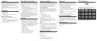
Most <strong>Sixnet</strong> components snap onto DIN rail strips fastened to a subpanel. Figure 2-1 shows a sample panel<br />
with DIN rail strips and wire duct attached. Recommended DIN rail spacing is 8 inches. This spacing allows<br />
room for wire duct to be installed without obstructing field wiring installation.<br />
The <strong>Sixnet</strong> components are typically installed against one another, but space may be left between modules to<br />
accommodate other DIN rail mounted components such as terminal blocks and fuse holders. End clamps are<br />
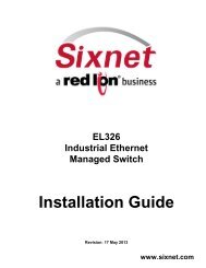
recommended to restrict side-to-side movement. Figure 2-2 shows the physical dimensions of the Micro-IPm.<br />
<strong>Sixnet</strong><br />
can be<br />
any<br />
and order<br />
Wire Duct<br />
8.0"<br />
(20.3 cm)<br />
components<br />
installed in<br />
orientation<br />
on your panel.<br />
Sample<br />
Layout for a<br />
36” x 30” Enclosure<br />
Wire Duct<br />
8.0"<br />
(20.3 cm)<br />
33.0"<br />
(83.8 cm)<br />
Wire Duct<br />
8.0"<br />
(20.3 cm)<br />
6.5"<br />
<strong>Sixnet</strong>, LLC Corporate Wire Headquarters Duct<br />
FLEXIBLE. (16.5 cm) RELIABLE. POWERFUL.<br />
331 Ushers Road, Ballston Lake, NY 12019 T +1 518 877 5173 F +1 518 877 8346<br />
www.sixnet.com<br />
27.0" (68.6 cm)<br />
Version XXX © 2010. <strong>Sixnet</strong>. All Rights Reserved. 10
0.28"<br />
(0.71 cm)<br />
4.25"<br />
(10.80 cm)<br />
2.95"<br />
(7.49 cm)<br />
FRONT VIEW<br />
0.28"<br />
SIDE VIEW<br />
3.23"<br />
(8.20 cm)<br />
Dia. 0.17"<br />
(0.43 cm) (clear<br />
for #8 screw)<br />
4.75"<br />
(12.07 cm)<br />
4.47"<br />
(11.35 cm)<br />
DIN<br />
EN<br />
50022<br />
Micro-IPm<br />
4.13"<br />
(10.48 cm)<br />
1.80"<br />
(4.57 cm)<br />
Typical<br />
DIN Rail<br />
Dimensions<br />
<strong>Sixnet</strong>, LLC Corporate Headquarters<br />
FLEXIBLE. RELIABLE. POWERFUL.<br />
331 Ushers Road, Ballston Lake, NY 12019 T +1 518 877 5173 F +1 518 877 8346<br />
www.sixnet.com<br />
Version XXX © 2010. <strong>Sixnet</strong>. All Rights Reserved. 11
Micro-IPm Mechanical Dimensions<br />
3 Power Supply Wiring<br />
The Micro-IPm accepts 10 to 30 VDC power from a <strong>Sixnet</strong> power supply or from a user DC power source. The<br />
<strong>Sixnet</strong> ST-PS-024-02N provides 24VDC @ 2A. The <strong>Sixnet</strong> RM-PS-024-01F provides 24VDC @ 1A.<br />
ST-PS-024-02N (24VDC @ 2A)<br />
The ST-PS-024-02N supply operates on 90 to 260VAC (47 to 63 Hz.). Refer to Figure 3-1 for connections.<br />
Tighten these screw terminals to a maximum of 3.48 in-lbs.<br />
90-260 VAC<br />
Line<br />
Neutral<br />
Power for controllers,<br />
RTUs, I/O, expanders,<br />
or user loops<br />
24 VDC<br />
+ -- - -<br />
ST-PS-024-02N<br />
Power Connections<br />
RM-PS-024-01F (24VDC @ 1A)<br />
The RM-PS-024-01F supply operates on 85-264 VAC (47-63 Hz) or 120-370 VDC. Refer to Figure 3-2 for<br />
connections. Tighten the screw terminals to a maximum of 3.48 in-lbs.<br />
<strong>Sixnet</strong>, LLC Corporate Headquarters<br />
FLEXIBLE. RELIABLE. POWERFUL.<br />
331 Ushers Road, Ballston Lake, NY 12019 T +1 518 877 5173 F +1 518 877 8346<br />
www.sixnet.com<br />
Version XXX © 2010. <strong>Sixnet</strong>. All Rights Reserved. 12
Chassis<br />
DC GND<br />
DC GND<br />
DC+ OUT<br />
DC+ OUT<br />
Opt. Auxiliary<br />
Power Input<br />
DC GND<br />
DC+ IN<br />
Line<br />
Line<br />
Neutral<br />
Neutral<br />
Chassis<br />
Wiring Base<br />
DC GND<br />
DC + IN<br />
DC GND<br />
DC GND<br />
DC GND<br />
DC GND<br />
DC GND<br />
DC GND<br />
DC GND<br />
DC GND<br />
DC+ OUT<br />
DC+ OUT<br />
DC+ OUT<br />
DC+ OUT<br />
DC+ OUT<br />
DC+ OUT<br />
DC+ OUT<br />
DC+ OUT<br />
Optional Auxiliary<br />
DC Power Input<br />
GND DC+<br />
Extra terminals<br />
for 4-20 loops,<br />
fields devices<br />
and more<br />
4-20<br />
Input<br />
Field<br />
Device<br />
Discrete<br />
Output<br />
Discrete<br />
Input<br />
AC Line<br />
Power Line<br />
Neutral<br />
Input Neutral<br />
Chassis GND<br />
RM-PS-024-01F Power Connections<br />
Optional<br />
Auxiliary<br />
DC Input<br />
DC Power for controllers,<br />
RTUs, I/O, and user loops<br />
DC + DC<br />
DC + Power<br />
DC --<br />
Output<br />
DC --<br />
Chassis GND<br />
RM-PS-024-01F Redundant Power<br />
The RM-PS-024-01F allows you to connect auxiliary 24 VDC power (from another RM-PS-024-01F or other<br />
source) to terminals 17 and 18. When auxiliary power is connected, the RM-PS-024-01F will source most of<br />
the power under normal operating conditions. If the primary power fails then the auxiliary power will<br />
immediately take over.<br />
3.1 Current Requirements<br />
To calculate the current requirements, add the wattage required for all the units to be powered. Then divide<br />
this by the DC power source voltage (typically 24 VDC) to get the steady state current requirement. To allow<br />
for startup surge we recommend that you size your power source so that it rated for at least twice what you<br />
need for a steady state current.<br />
DC Power Wiring<br />
All <strong>Sixnet</strong> units and user instrumentation loops may be powered from a single DC source. Refer to Figure 4-1<br />
for DC power connections to the Micro-IPm. The user DC power source must be in the range of 10 to 30 volts.<br />
<strong>Sixnet</strong>, LLC Corporate Headquarters<br />
FLEXIBLE. RELIABLE. POWERFUL.<br />
331 Ushers Road, Ballston Lake, NY 12019 T +1 518 877 5173 F +1 518 877 8346<br />
www.sixnet.com<br />
Version XXX © 2010. <strong>Sixnet</strong>. All Rights Reserved. 13
4 I/O Wiring<br />
4.1 On-board I/O Overview<br />
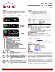
The Micro-IPm comes with integrated discrete and/or analog I/O built-in. Wiring for the available on-board I/O<br />
should be made based on the wiring diagram shown in Figure 4-1. A hardware summary for each of the<br />
available I/O is described below. Further details on the features available when using the on-board I/O can be<br />
found in the electronic help system in the <strong>Sixnet</strong> I/O Tool Kit.<br />
<strong>VT</strong>-UIPM-431 8 DI 4 DO 2 AI<br />
<strong>VT</strong>-UIPM-441 8 DI 4 DO 0 AI<br />
4.2 Discrete Inputs<br />
There are eight discrete inputs that accept signals in the range of 10-30 VDC. Refer to figure 4-1 for exact<br />
terminal locations. A single terminal is provided for each input channel.<br />
Sinking or Sourcing<br />
All eight discrete inputs can be sourcing (ON when positive voltage is applied). All eight discrete inputs may<br />
also be configured as sinking inputs (switch closures to ground). There is a selection jumper in the module’s<br />
base that is easily accessed by unplugging the logic module and opening the hinged door. Refer to figure 4-1.<br />
You must also make a similar selection in the I/O Tool Kit software. The module performs a check to verify that<br />
the hardware and software selections match.<br />
Adjustable Threshold Voltage<br />
All eight discrete inputs may be modified to transition at a threshold voltage lower than the factory setting. This<br />
is accomplished by simply soldering an extra resistor into the base. Contact <strong>Sixnet</strong> for details.<br />
High Speed and Special Counter Inputs<br />
All eight discrete inputs can be configured in the <strong>Sixnet</strong> I/O Tool Kit as counters with a flexible choice of<br />
modes. These counters report their values in corresponding 16-bit analog input registers. Options for fast (5<br />
<strong>Sixnet</strong>, LLC Corporate Headquarters<br />
FLEXIBLE. RELIABLE. POWERFUL.<br />
331 Ushers Road, Ballston Lake, NY 12019 T +1 518 877 5173 F +1 518 877 8346<br />
www.sixnet.com<br />
Version XXX © 2010. <strong>Sixnet</strong>. All Rights Reserved. 14
mS) or slow (25 mS for contact bounce filtering) response provide a maximum count rate of 100 Hz or 20 Hz<br />
counting, respectively. The 1 st channel is a high speed counter and can count up to 10 KHz. Available counter<br />
modes are pulse, rate and run-time.<br />
4.3 Discrete Outputs<br />
The discrete output channels each provide up to 1 Amp DC to power motor contactors, valves, and other<br />
loads. A single terminal is provided for each output channel. All outputs are powered from the 10-30 VDC<br />
power terminals. All channels are referenced to a common return, which is connected to the negative side<br />
(ground) of the DC power source. Refer to figure 4-1.<br />
Sourcing Discrete Outputs<br />
All four discrete outputs are sourcing (positive voltage outputed when ON) with the standard 10-30V range.<br />
Watchdog Output<br />
The first discrete output can be configured to be a watchdog output. This system performance monitor will be<br />
ON if the output circuitry, CPU operation and internal communications are functioning normally.<br />
4.4 Analog Inputs<br />
There are optionally two analog inputs on your Micro-IPm. These inputs provide 16 bits of resolution for<br />
precision analog measurements. A single input terminal is provided for each measurement channel. Care<br />
must be taken to externally provide a suitable instrumentation ground for these single ended input circuits.<br />
Precision 100 ohm current shunts beneath the hinged access door in the wiring base pass current and<br />
maintain loop integrity, even if the plug-in logic module is removed. Each analog channel has built in current<br />
protection circuitry, such that each channel open circuits before any circuit damage will occur.<br />
Self-resetting Analog Input Protection<br />
Each 4-20 mA input channel has a 100 ohm, high precision (0.1 percent) shunt across its input to develop a 2<br />
volt signal when a full scale 20 mA input is applied. These shunts are located in the module’s base, giving you<br />
the advantage of maintaining a continuous circuit even if the logic module is removed from the base. If<br />
excessive voltage is applied to an input, a self-resetting fuse will open to prevent the shunt from overheating.<br />
Open Loop Detection on Analog Inputs<br />
The Micro-IPm can detect and report an open instrumentation loop on its analog inputs. By allowing the<br />
module to report a negative value if the current falls below 4 mA, low limit logic in your DCS, PLC, RTU or<br />
computer can signal the loss of current. To enable this feature, select the “Go Negative Below 4 mA” software<br />
setting for each channel.<br />
Reading Voltage Analog Inputs<br />
For each analog input, jumpers may be moved to convert the channel from 4-20 mA to 0-5 V. For example, in<br />
the diagram below, we see that both jumpers for the AI1 channel are in the “down” position for 4-20 mA. If we<br />
want AI1 to be 0-5 V, both jumpers for that channel must be placed in the “up” position instead. In addition,<br />
voltage operation must also be configured in the I/O Tool Kit by selecting the appropriate range for the<br />
corresponding input. Additional, factory modifications to the base can be made to allow for 0-2V and 0-10V<br />
ranges. Contact <strong>Sixnet</strong>.<br />
<strong>Sixnet</strong>, LLC Corporate Headquarters<br />
FLEXIBLE. RELIABLE. POWERFUL.<br />
331 Ushers Road, Ballston Lake, NY 12019 T +1 518 877 5173 F +1 518 877 8346<br />
www.sixnet.com<br />
Version XXX © 2010. <strong>Sixnet</strong>. All Rights Reserved. 15
+<br />
-<br />
GND<br />
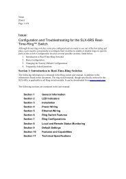
Micro-IPm diagram for power, communication, and on-board I/O wiring<br />
For sourcing<br />
inputs, connect<br />
to 10-30 VDC+<br />
and set the<br />
Return Jumper<br />
for "DC-".<br />
For sinking<br />
inputs, connect<br />
to 10-30 VDCand<br />
set the<br />
Return Jumper<br />
for "DC+".<br />
RS485<br />
(Port A)<br />
T<br />
19 20<br />
DI Return Jumper:<br />
Select DC- for<br />
sourcing (default)<br />
or DC+ for sinking<br />
1<br />
+ -<br />
2<br />
21 22<br />
3<br />
4<br />
DI<br />
(sourcing or sinking DI)<br />
10-30 VDC<br />
(<strong>User</strong> Supplied)<br />
Chassis<br />
GND<br />
23<br />
DO<br />
1 2 3 4 5 6 7 8 9 10 11 12 13<br />
5<br />
6<br />
7 8<br />
AI1<br />
0-5<br />
4-20<br />
24<br />
1<br />
25<br />
AI2<br />
0-5<br />
4-20<br />
2<br />
3 4<br />
(sourcing<br />
DO)<br />
RS232<br />
RJ45<br />
(Port B)<br />
AI Range Jumper:<br />
Select 4-20 mA<br />
(default) or 0-5 V<br />
1<br />
AI<br />
14<br />
2<br />
Ethernet<br />
RJ45<br />
(10/100)<br />
RS232<br />
(Port C)<br />
15 16<br />
X T D D XR TR<br />
S<br />
(loop or self<br />
powered AI)<br />
17 18<br />
RS232<br />
Ground<br />
<strong>VT</strong>-UIPM-431 with 8 DI, 4 DO, 2 AI, 1 RS485 & 2 RS232<br />
RS232 RS232<br />
DI<br />
DO (Port D) (Port C)<br />
1 2 3 4 5 6 7 8 9 10 11 12 13 14 15 16 17 18<br />
DI and DO wiring same as above<br />
R T R R RS232<br />
X T X XD TS<br />
D D X D<br />
Ground<br />
<strong>VT</strong>-UIPM-441 with 8 DI, 4 DO, 1 RS485 & 3 RS232<br />
10-30<br />
VDC<br />
Equivalent DI Circuits<br />
Jumper<br />
Jumper<br />
Ref<br />
Ref<br />
GND<br />
DC+<br />
5.1Kohms<br />
DIN<br />
Sourcing<br />
Input<br />
Switch<br />
Sinking<br />
Input<br />
Switch<br />
Equivalent DO Circuit<br />
(sourcing only)<br />
DC+<br />
Solid State<br />
Switch<br />
GND<br />
DC+<br />
5.1Kohms<br />
DIN<br />
DOUT<br />
GND<br />
Load<br />
Equivalent AI Circuit<br />
AIN<br />
100 ohms (4-20 mA)<br />
or 80K ohms (0-5 V)<br />
GND<br />
<strong>Sixnet</strong>, LLC Corporate Headquarters<br />
FLEXIBLE. RELIABLE. POWERFUL.<br />
331 Ushers Road, Ballston Lake, NY 12019 T +1 518 877 5173 F +1 518 877 8346<br />
www.sixnet.com<br />
Version XXX © 2010. <strong>Sixnet</strong>. All Rights Reserved. 16
5 Communications<br />
5.1 Communication Ports<br />
The Micro-IPm has two available port combinations, depending on the model number. See the chart below.<br />
Product<br />
RS485<br />
Port A<br />
RS232<br />
Port B<br />
RS232<br />
Port C<br />
RS232<br />
Port D<br />
Ethernet<br />
Port<br />
<strong>VT</strong>-UIPM-431 -- <br />
<strong>VT</strong>-UIPM-441 <br />
5.1.1 RS232 Port B<br />
An RJ45 female connector is provided for this port. The pin-outs follow the EIA/TIA-561standard (See Figure 5-<br />
3). A pre-wired DB9F to RJ45F adapter is included with these units. Use this adapter along with a RJ45 male<br />
to RJ45 male straight-thru wired patch cable (not included) to make a connection between a com port on your<br />
PC (DB9 male) and Port B (RJ45 female). Refer to the <strong>Sixnet</strong> I/O Tool Kit help for more wiring information.<br />
When connecting a modem, insert the colored wires of the RJ45 to DB9 male adapter into the appropriate<br />
sockets of the DB9 male connector according to the table below. Then plug the adapter’s DB9 male connector<br />
directly onto the DB9 RS232 port of a <strong>VT</strong>-MODEM-xxx. Connect a straight-through Ethernet cable between the<br />
<strong>Sixnet</strong> RJ45 port and the RJ45 to DB9 male (modem) adapter.<br />
The RJ45 serial port connector bodies on <strong>Sixnet</strong> products are metallic and are connected to the Chassis GND<br />
terminal. Therefore, shielded cables may be used to provide further protection. To prevent ground loops, the<br />
cable shield should be tied to the metal connector body at one end of the cable only.<br />
Typical Modem Adapter Wiring:<br />
<strong>Sixnet</strong> RJ45F to DB9M <strong>Sixnet</strong><br />
RJ45F Pin #, Adapter DB9 Male Connector<br />
Signal Name wire color Pin #, Signal Name<br />
1 RI/DSR in Blue 9 RI out<br />
2 DCD in Orange 1 DCD out<br />
<strong>Sixnet</strong>, LLC Corporate Headquarters<br />
FLEXIBLE. RELIABLE. POWERFUL.<br />
331 Ushers Road, Ballston Lake, NY 12019 T +1 518 877 5173 F +1 518 877 8346<br />
www.sixnet.com<br />
Version XXX © 2010. <strong>Sixnet</strong>. All Rights Reserved. 17
3 DTR out Black 4 DTR in<br />
4 GND Red 5 GND<br />
5 RXD in Green 2 RXD out<br />
6 TXD out Yellow 3 TXD in<br />
7 CTS in Brown 8 CTS out<br />
8 RTS out White 7 RTS in<br />
Typical PC Adapter Wiring:<br />
<strong>Sixnet</strong><br />
RJ45F to DB9F<br />
RJ45F Pin #, Adapter DB9 Female Connector<br />
Signal Name wire color Pin #, Signal Name<br />
1 RI/DSR in Blue 4 DTR out<br />
2 DCD in Orange N/C<br />
3 DTR out Black 6 DSR in<br />
4 GND Red 5 GND<br />
5 RXD in Green 3 TXD out<br />
6 TXD out Yellow 2 RXD in<br />
7 CTS in Brown 7 RTS out<br />
8 RTS out White 8 CTS in<br />
5.1.2 RS232 Ports C & D<br />
Port C is a four wire RS232 port with TXD, RXD, RTS and GND. Port D is a three wire RS232 port with TXD,<br />
RXD and GND. (The CTS signal is not supported on these ports. Use Port B if you need CTS.) Depending on<br />
your application, you may wish to wire the interface (see Figure 5-3) with a DB9 male or DB9 female<br />
connector. Figure 5-1 shows the pin-outs of male and female DB9 connectors.<br />
Note: Terminal 18 is a common ground and is shared by both ports and the I/O.<br />
There are two ways to connect Port C to a PC:<br />
Make connections from the μIPm screw terminals to a DB9F (female) connector and plug the female connector<br />
directly onto your PC.<br />
Make connections from the μIPm screw terminals to a DB9M (male) connector and plug the male connector<br />
onto one end of a Plant Floor RS232 cable (part number ST-CABLE-PF). Then plug the other end of the ST-<br />
CABLE-PF onto your PC. This wiring method allows you to plug the DB9M directly onto a <strong>VT</strong>-MODEM-xxx as<br />
well.<br />
Make connections from the screw terminals of the Micro-IPm-xxx to a DB9 male or DB9 female connector<br />
according to table 5-1 below.<br />
<strong>Sixnet</strong>, LLC Corporate Headquarters<br />
FLEXIBLE. RELIABLE. POWERFUL.<br />
331 Ushers Road, Ballston Lake, NY 12019 T +1 518 877 5173 F +1 518 877 8346<br />
www.sixnet.com<br />
Version XXX © 2010. <strong>Sixnet</strong>. All Rights Reserved. 18
Micro-IPm-xxx-D DB9M to ST-CABLE-PF DB9F to<br />
Port C, D or <strong>VT</strong>-MODEM-xxx PC Com Port<br />
Terminal # Pin #, Signal Name Pin #, Signal Name<br />
18 GND 5 GND 5 GND<br />
16 RXD in 2 RXD 3 TXD<br />
15 TXD out 3 TXD 2 RXD<br />
N/A 8 CTS 7 RTS<br />
17 RTS out (port C only) 7 RTS 8 CTS<br />
RJ45 Connectors<br />
5.1.3 RS485 Port A<br />
There is one RS485 port available on the unit (See Figure 5-3 for the location of the port). The RS485 port<br />
establishes a 2-wire, half duplex only connection to <strong>Sixnet</strong>’s RemoteTRAK I/O modules or other equipment.<br />
Four terminals (for signal GND, 485+, 485-, & termination) are provided for each available RS485 interface.<br />
Generally, you connect + to + and – to – between units. However, since there is no standard for RS485<br />
terminal designations you may need to connect + to – and – to + in some cases. No damage will result if you<br />
connect incorrectly. It is highly recommended that you tie the signal ground to an appropriate ground (if<br />
available) between all RS485 units. Make sure to use a good quality communication cable with three<br />
conductors (twisted is preferred) plus a shield. To prevent ground loops, the shield should be connected to<br />
chassis ground on only one end of any cable run.<br />
Note: If you have existing wiring that has only two conductors and a shield, you can use the shield to connect<br />
the signal grounds between stations. This is not optimal (especially for long cable runs) but should work in<br />
most situations.<br />
RS485 Termination: The Micro-IPm has RS485 termination components (150 ohm resistor and a 0.01 F<br />
capacitor connected in series) already inside for each RS485 port. To terminate your RS485 network just tie<br />
the “T” terminal to the RS485 ‘–‘ terminal. Make sure to use the same type and size conductor as used already<br />
used for your RS485 ‘–‘ connection. It is recommended that both end stations of your RS485 network be<br />
terminated. Avoid terminating more than two stations. Refer to the RemoteTRAK I/O <strong>User</strong> <strong>Manual</strong> on how to<br />
terminate a RemoteTRAK I/O Module. For 3 rd party devices, please refer to their user manual for termination<br />
instructions.<br />
Bias Resistors: On a RS485 2-wire network, a pair of bias resistors (1K ohm typically) acting upon the<br />
transmit/receive wires may be required. If bias resistors are not present, the receive inputs on some RS485<br />
devices may react to noise on the floating wires. The bias resistors will force the transmit/receive wires to a<br />
known (non-floating) state when none of the RS485 devices are transmitting data. Some RS485 devices have<br />
<strong>Sixnet</strong>, LLC Corporate Headquarters<br />
FLEXIBLE. RELIABLE. POWERFUL.<br />
331 Ushers Road, Ballston Lake, NY 12019 T +1 518 877 5173 F +1 518 877 8346<br />
www.sixnet.com<br />
Version XXX © 2010. <strong>Sixnet</strong>. All Rights Reserved. 19
ias resistors built-in, and are enabled through DIP-switch or jumper settings. Make sure there is only one pair<br />
of bias resistors acting upon the network.<br />
Note: If your RS485 network is made up exclusively of <strong>Sixnet</strong> devices then these bias resistors are not<br />
necessary.<br />
5.1.4 Ethernet Port<br />
This port is a 10/100BaseTx auto-detecting and auto-crossover Ethernet port (see Figure 5-3 for RJ45 pin<br />
locations). This means it will auto-detect the speed, and work with either a straight-thru or cross-wired Ethernet<br />
cable. A standard shielded RJ45 connector is provided. See the figures below for the pin-outs. This port has a<br />
fixed unique MAC address. The IP address can be set with the <strong>Sixnet</strong> I/O Tool Kit software. Refer to the<br />
electronic help for details.<br />
Ethernet RJ45 (10/100)<br />
RS232<br />
Port B (RJ45)<br />
RS485 Port A<br />
2 RS232 PORT D<br />
RS232 Port C<br />
RS232 Port B<br />
1. RI/DSR in<br />
2. DCD in<br />
3. DTR out<br />
4. GND<br />
5. RXD in<br />
6. TXD out<br />
7. CTS out<br />
8. RTS out<br />
(EIA/TIA-561)<br />
Ethernet RJ45<br />
1. TX+<br />
2. TX-<br />
3. RX+<br />
6. RX-<br />
RS485 Port A<br />
SCW 19: GND<br />
SCW 20: +<br />
SCW 21: -<br />
SCW 22: T<br />
RS232 Port C<br />
SCW 15: TXD<br />
SCW 16: RXD<br />
SCW 17: RTS<br />
SCW 18:<br />
GND<br />
RS232 Port D<br />
SCW 13: TXD<br />
SCW 14: RXD<br />
SCW 18:<br />
GND<br />
<strong>Sixnet</strong>, LLC Corporate Headquarters<br />
FLEXIBLE. RELIABLE. POWERFUL.<br />
331 Ushers Road, Ballston Lake, NY 12019 T +1 518 877 5173 F +1 518 877 8346<br />
www.sixnet.com<br />
Version XXX © 2010. <strong>Sixnet</strong>. All Rights Reserved. 20
6 Technical Specifications<br />
Here are the technical specifications for the VersaTRAK μIPm RTU / Controller.<br />
General<br />
Industrial PowerPC (32 bit data bus)<br />
Compatibility with legacy Mini VersaTRAK RTU Fully compatible with an assortment of on board I/O<br />
Local I/O (on board) Up to 14<br />
Operating system<br />
Embedded LINUX<br />
Unique station addresses (unit Ids)<br />
16,000+ (<strong>Sixnet</strong>) or 247 (Modbus)<br />
Dynamic memory (RAM) (for program execution, 16 Megabytes<br />
dynamic variables, dynamic file system, etc.)<br />
Program memory (Flash)<br />
16 Megabytes<br />
(for Linux OS, program storage, and file system)<br />
Datalogging memory (RAM)<br />
(for datalogging and retained variables)<br />
Battery-backed – Rechargeable Lithium<br />
512K bytes<br />
Battery-backup time / life<br />
1 year / 10+ years<br />
Real-time clock resolution<br />
10 mS<br />
Real-time clock accuracy<br />
+/-15 seconds per month<br />
I/O expansion<br />
EtherTRAK, RemoteTRAK<br />
Maximum distributed I/O<br />
256 physical I/O<br />
Maximum virtual I/O registers<br />
256 per I/O type (more available – contact <strong>Sixnet</strong> for details)<br />
Datalogging support<br />
Yes – <strong>Sixnet</strong> Sixlog<br />
Datalogging modes<br />
Trending, alarm logging, sequence of events, event initiated,<br />
client transfers, and others<br />
LINUX capabilities<br />
Practically unlimited<br />
Programming<br />
High level C and others<br />
Number of applications allowed<br />
As many as there is memory for<br />
Available FREE source code<br />
Practically unlimited<br />
IEC 61131 PLCopen programming<br />
Yes – <strong>Sixnet</strong> ISaGRAF<br />
Languages supported<br />
Ladder logic, function chart, function block, instruction list,<br />
structured text, and flow chart<br />
Cycle time<br />
10 mS minimum (user settable)<br />
Communication capabilities<br />
Master, slave, peer to peer, report on exception, store and<br />
forward and more<br />
Communication media supported<br />
Ethernet, telemetry, telephone (dialup and leased line), radio<br />
(dumb and smart), other wireless, fiber optic, short haul and<br />
more<br />
Watchdogs and Monitors<br />
For run-time diagnostics<br />
CPU watchdog<br />
CPU automatically resets if error is detected; status LED<br />
flashes error code<br />
<strong>Sixnet</strong>, LLC Corporate Headquarters<br />
FLEXIBLE. RELIABLE. POWERFUL.<br />
331 Ushers Road, Ballston Lake, NY 12019 T +1 518 877 5173 F +1 518 877 8346<br />
www.sixnet.com<br />
Version XXX © 2010. <strong>Sixnet</strong>. All Rights Reserved. 21
Communications watchdog<br />
Settable timeout and output action (force off or freeze)<br />
Heartbeat watchdog<br />
Settable timeout & output action (force off or freeze)<br />
Ethernet Port(s)<br />
10/100BaseTx (auto-detecting)<br />
Connection<br />
RJ45 (auto-crossover)<br />
Isolation<br />
1500 Volts RMS 1 minute (60 Hz.)<br />
Message response time (typical)<br />
5 mS<br />
Diagnostic LEDs<br />
Indicates speed and activity<br />
Protocols supported<br />
TCP/IP, ARP, UDP, ICMP, DHCP, Modbus/TCP,<br />
Modbus/UDP, <strong>Sixnet</strong>, and more<br />
Network port<br />
1 shielded RJ45 connector<br />
Serial Ports<br />
300 to 115,200 baud<br />
RS485 Port A<br />
Screws (GND, 485+, 485-, termination) (2-wire halfduplex)<br />
RS485 network<br />
Up to 32 (full-load) stations<br />
RS485 distance<br />
Up to 0.5 miles (1 km)<br />
RS232 Port B RJ45 (TD, RD, CTS, RTS, CD, DTR, DSR/RI ,<br />
GND)<br />
RS232 Port C<br />
RJ45 (TD, RD, RTS, GND)<br />
RS232 Port D<br />
RJ45 (TD, RD, GND)<br />
Protocols (master & slave)<br />
<strong>Sixnet</strong> & Modbus (RTU and ASCII); Many others<br />
available in LINUX<br />
Diagnostic LEDs on each port<br />
Yes<br />
Flow Control<br />
Hardware, software, RTS-party (for radios and<br />
RS485)<br />
Discrete Inputs<br />
8 Channels - sourcing or sinking (selectable)<br />
Guaranteed ON Voltage<br />
9 VDC (this threshold is factory adjustable to turn on<br />
at a lower voltage - Contact <strong>Sixnet</strong> for details)<br />
Maximum Voltage<br />
30 VDC<br />
Guaranteed OFF<br />
5.0 VDC & 1.5mA DC<br />
Input Resistance<br />
10K Ohms<br />
Input Current @ 24V<br />
3 mA<br />
Filtered ON/OFF delay<br />
25ms (20Hz max. counting) for contact bounce<br />
filtering<br />
Fast ON/OFF delay<br />
4 ms (100Hz max counting)<br />
Count Rate<br />
10khz on channel 1, see above for other rates<br />
Count modes<br />
Pulse, rate and run-time<br />
Poll time (all channels)<br />
5 mS to 20 mS – configuration dependent<br />
Discrete Outputs<br />
4 channels – sourcing only<br />
Operating voltage<br />
10-30 VDC<br />
Maximum Output per channel<br />
1 Amp<br />
Maximum Output per module<br />
8 Amps<br />
Max. OFF state leakage<br />
0.05 mA<br />
Minimum Load<br />
1 mA<br />
Inrush current<br />
5 Amps (100 ms surge)<br />
Typical ON resistance<br />
0.3 ohms<br />
Typical ON voltage (@1A)<br />
0.3 VDC<br />
Watchdog output Configurable on channel 1<br />
Poll time (all channels)<br />
5 mS to 20 mS – configuration dependent<br />
Analog Inputs<br />
2 channels (4-20 mA by default)<br />
Range 4-20 mA or 0-5 V (optionally 0-2 V or 0-10 V)<br />
<strong>Sixnet</strong>, LLC Corporate Headquarters<br />
FLEXIBLE. RELIABLE. POWERFUL.<br />
331 Ushers Road, Ballston Lake, NY 12019 T +1 518 877 5173 F +1 518 877 8346<br />
www.sixnet.com<br />
Version XXX © 2010. <strong>Sixnet</strong>. All Rights Reserved. 22
A/D resolution 16 bits (0.003%)<br />
Full scale accuracy<br />
+/- 0.1% (@20C)<br />
Span and offset temp. coef.<br />
+/- 50 ppm per degree C<br />
Input impedance<br />
100 Ohm<br />
Current protection<br />
Self-resetting fuses<br />
DMRR (differential mode rejection)<br />
66 dB at 50/60 Hz<br />
Fastest poll time (all channels)<br />
50 mS – settable integration time for more noise<br />
filtering<br />
I/O Tool Kit Windows Software<br />
Level 1 provided free with all systems<br />
Operating systems<br />
95, 98, ME, NT, 2000, and XP<br />
Minimum system requirements<br />
Pentium or equivalent, 32 Mb RAM, 100 Mb hard<br />
disk space<br />
Level 1 (Basic - FREE)<br />
Configuration, calibration, diagnostics, limited<br />
exporting of I/O definitions and quick load feature<br />
“Load All”<br />
SCS option group<br />
Full importing and exporting of I/O definitions and<br />
peer to peer I/O transfers<br />
Datalogging option group<br />
Datalogging capability and datalog server<br />
Linux Advanced Development option<br />
LINUX functionality and support.<br />
group<br />
Available IPm add-on software<br />
HART, PPP, IP Tables, DNP3, AGA and more<br />
Environmental<br />
DIN rail or flat panel mount<br />
Input voltage<br />
10-30 VDC (integrated switching supply),<br />
(External AC/DC or DC/DC supplies optional)<br />
Input power (@ 24 VDC unless otherwise<br />
noted)<br />
<strong>VT</strong>-UIPM:<br />
2.4 W (100mA) – typical (no communications)<br />
(+/-10%)<br />
Temperature<br />
-40 to 70°C (-40 to 85°C storage)<br />
Humidity<br />
5% to 95% RH (non-condensing)<br />
(optional conformal coating)<br />
Flammability<br />
UL 94V-0 materials<br />
Electrical Safety<br />
UL 508, CSA C22.2/14; EN61010-1 (IEC1010); CE<br />
EMI emissions<br />
FCC part 15, ICES-003, Class A; EN55022;<br />
EN61326-1; CE<br />
EMC immunity<br />
EN61326-1 (EN61000-4-2,3,4,6); CE<br />
Surge withstand IEEE-472 (ANSI C37.90); EN61000-4-2, 4<br />
Vibration<br />
IEC68-2-6<br />
Hazardous locations<br />
(Class 1, Div 2, Groups A, B, C, D)<br />
ANSI / ISA12.12.01, CSA C22.2/213,<br />
IEC60079-0, -15 (Zone 2), ATEX<br />
Marine & Offshore<br />
DNV (Det Norske Veritas)<br />
Packaging<br />
IP20 Lexan Packaging<br />
Mounting<br />
Size<br />
DIN rail (EN50022) or direct to panel<br />
4.75”L x 3.25”W x 4.13”H<br />
(12.07cm L x 8.26cm W x 10.48cm H)<br />
<strong>Sixnet</strong>, LLC Corporate Headquarters<br />
FLEXIBLE. RELIABLE. POWERFUL.<br />
331 Ushers Road, Ballston Lake, NY 12019 T +1 518 877 5173 F +1 518 877 8346<br />
www.sixnet.com<br />
Version XXX © 2010. <strong>Sixnet</strong>. All Rights Reserved. 23
7 Maintenance Information<br />
7.1 Local Diagnostics<br />
Local diagnostics can be performed through any available port while the Micro-IPm is responding to messages<br />
from the other port. Diagnostic software, such as the <strong>Sixnet</strong> I/O Tool Kit, can be used to display the status of<br />
the I/O registers. Refer to the software’s help system for details.<br />
7.2 Power and Status LED<br />
The “PWR” LED on the Micro-IPm indicates its operational and power status:<br />
ON<br />
OFF<br />
FAST BLINK<br />
SLOW or PERODIC<br />
BLINK<br />
The Micro-IPm is operating properly.<br />
There is no power to the Micro-IPm or service is required. Contact <strong>Sixnet</strong><br />
technical support.<br />
This may occur when the Micro-IPm is being reset, or firmware is to be<br />
downloaded from the I/O Tool Kit software.<br />
This indicates that the internal watchdog has detected a problem. Try clearing<br />
the memory and reloading the project from the I/O Tool Kit.<br />
7.3 Controller or RTU Memory<br />
The Micro-IPm has nonvolatile (battery-free) memory for storing configuration data from the I/O Tool Kit utility.<br />
It also has battery-backed memory for storage of program variables and logged data. The battery is a<br />
rechargeable lithium cell that is kept fresh by the power circuitry in the Micro-IPm. The memory retention period<br />
for an unpowered Micro-IPm is at least 6-months at room temperature. The retention time will be shorter at<br />
higher temperatures. The life expectancy of the lithium battery is approximately 10 years or more.<br />
<strong>Sixnet</strong>, LLC Corporate Headquarters<br />
FLEXIBLE. RELIABLE. POWERFUL.<br />
331 Ushers Road, Ballston Lake, NY 12019 T +1 518 877 5173 F +1 518 877 8346<br />
www.sixnet.com<br />
Version XXX © 2010. <strong>Sixnet</strong>. All Rights Reserved. 24
8 Service Information<br />
We sincerely hope that you never experience a problem with any <strong>Sixnet</strong> product. If you do need service, call<br />
<strong>Sixnet</strong> at (518) 877-5173 and ask for Applications Engineering. A trained specialist will help you to quickly<br />
determine the source of the problem. Many problems are easily resolved with a single phone call. If it is<br />
necessary to return a unit to us, an RMA (Return Material Authorization) number will be given to you.<br />
<strong>Sixnet</strong> tracks the flow of returned material with our RMA system to ensure speedy service. You must include<br />
this RMA number on the outside of the box so that your return can be processed immediately.<br />
The applications engineer you are speaking with will fill out an RMA request for you. If the unit has a serial<br />
number, we will not need detailed financial information. Otherwise, be sure to have your original purchase<br />
order number and date purchased available.<br />
We suggest that you give us a repair purchase order number in case the repair is not covered under our<br />
warranty. You will not be billed if the repair is covered under warranty.<br />
Please supply us with as many details about the problem as you can. The information you supply will be<br />
written on the RMA form and supplied to the repair department before your unit arrives. This helps us to<br />
provide you with the best service, in the fastest manner. Normally, repairs are completed in two days.<br />
Sometimes difficult problems take a little longer to solve.<br />
If you need a quicker turnaround, ship the unit to us by air freight. We give priority service to equipment that<br />
arrives by overnight delivery. Many repairs received by mid-morning (typical overnight delivery) can be finished<br />
the same day and returned immediately.<br />
We apologize for any inconvenience that the need for repair may cause you. We hope that our rapid service<br />
meets your needs. If you have any suggestions to help us improve our service, please give us a call. We<br />
appreciate your ideas and will respond to them.<br />
For Your Convenience:<br />
Please fill in the following and keep this manual with your <strong>Sixnet</strong> system for future reference:<br />
P.O. #:__________________ Date Purchased: ___________________<br />
Purchased From:______________________________________________<br />
<strong>Sixnet</strong>, LLC Corporate Headquarters<br />
FLEXIBLE. RELIABLE. POWERFUL.<br />
331 Ushers Road, Ballston Lake, NY 12019 T +1 518 877 5173 F +1 518 877 8346<br />
www.sixnet.com<br />
Version XXX © 2010. <strong>Sixnet</strong>. All Rights Reserved. 25
8.1 Product Support<br />
To obtain support for <strong>Sixnet</strong> products, call <strong>Sixnet</strong> and ask for Applications Engineering. Our phone numbers<br />
are:<br />
Phone: +1 (518) 877-5173<br />
Fax: +1 (518) 877-8346<br />
E-mail: mailto: support@sixnet.com<br />
Visit us on the Web: http://www.sixnet.com<br />
Our mailing address:<br />
<strong>Sixnet</strong> Technology Park<br />
331 Ushers Road<br />
Ballston Lake, NY 12019<br />
<strong>Sixnet</strong>, LLC Corporate Headquarters<br />
FLEXIBLE. RELIABLE. POWERFUL.<br />
331 Ushers Road, Ballston Lake, NY 12019 T +1 518 877 5173 F +1 518 877 8346<br />
www.sixnet.com<br />
Version XXX © 2010. <strong>Sixnet</strong>. All Rights Reserved. 26