MODEL PPU-231 User's Manual
MODEL PPU-231 User's Manual
MODEL PPU-231 User's Manual

Create successful ePaper yourself
Turn your PDF publications into a flip-book with our unique Google optimized e-Paper software.
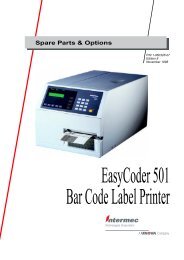
LINE THERMAL PRINTER/<br />
PRESENTER UNIT<br />
<strong>MODEL</strong> <strong>PPU</strong>-<strong>231</strong><br />
User’s <strong>Manual</strong>
<strong>PPU</strong>-<strong>231</strong> User’s <strong>Manual</strong><br />
Declaration of Conformity<br />
This printer conforms to the following Standards:<br />
Low Voltage Directive 73/23/EEC, 93/68/EEC and the EMC Directive 89/336/EEC,<br />
92/31/EEC, 93/68/EEC.<br />
LVD : EN60950<br />
EMC : EN55022<br />
EN61000-3-2<br />
EN61000-3-3<br />
EN55024<br />
Class A<br />
This declaration is applied only for 230V model.<br />
WARNING : This is a Class A products. In a domestic environment this product may cause radio interference in<br />
which case the user may be required to take adequate measures.<br />
CITIZEN is a registered trade mark of CITIZEN WATCH CO., LTD., Japan<br />
CITIZEN es una marca registrada de CITIZEN WATCH CO., LTD., Japón<br />
CITIZEN
<strong>PPU</strong>-<strong>231</strong> User’s <strong>Manual</strong><br />
IMPORTANT SAFETY INSTRUCTIONS<br />
• Read all of these instructions and save them for future reference.<br />
• Follow all warnings and instructions marked on the product.<br />
• Unplug this product from the wall outlet before cleaning. Do not use liquid or aerosol cleaners. Use<br />
a damp cloth for cleaning.<br />
• Do not use this product near water.<br />
• Do not place this product on an unstable cart, stand or table. The product may fall, causing serious<br />
damage to the product.<br />
• Slots and openings on the back or bottom of the case are provided for ventilation. To ensure reliable<br />
operation of the product and to protect it from overheating, do not block or cover these openings. The<br />
openings should never be blocked by placing the product on a bed, sofa, rug of other similar surface.<br />
This product should never be placed near or over a radiator or heater. This product should not be<br />
placed in an built-in installation unless proper ventilation is provided.<br />
• This product should be operated from the type of power source indicated on the marking label. If you<br />
re not sure of the type of power available, consult your dealer or local power company.<br />
• Do not allow anything to rest on the power cord. Do not place this product where the cord will be<br />
walked on.<br />
• If an extension cord is used with this product, make sure that the total of the ampere ratings of the<br />
products plugged into the extension cord does not exceed the extension cord ampere rating. Also,<br />
make sure that the total of all products plugged into the wall outlet does not exceed 15 amperes.<br />
• •Never push objects of any kind into this product through cabinet slots as they may touch dangerous<br />
voltage points or short out parts that could result in a risk of fire or electric shock. Never spill liquid<br />
of any kind on the product.<br />
• Except as explained elsewhere in this manual, do not attempt to service this product by yourself.<br />
Opening and removing the covers that are marked “Do Not Remove” may expose you to dangerous<br />
voltage points or other risks. Refer all servicing on those compartments to service personnel.<br />
• •Unplug this product from the wall outlet and refer servicing to qualified service personnel under the<br />
following conditions:<br />
A. When the power cord or plug is damaged or frayed.<br />
B. If liquid has been spilled into the product.<br />
C. If the product has been exposed to rain or water.<br />
D. If the product does not operate normally when the operating instructions are followed. Adjust only<br />
those controls that are covered be the operating instructions since improper adjustment of other<br />
controls may result in damage and will often require extensive work by a qualified technician to<br />
restore the product to normal operation.<br />
E. If the product has been dropped or the cabinet has been damaged.<br />
F. If the product exhibits a distinct change in performance, indicating a need for service.<br />
• Please keep the poly bag which this equipment is packed in away from children or throw it away to<br />
prevent children from putting it on. Putting it on may cause suffocation.<br />
CITIZEN
<strong>PPU</strong>-<strong>231</strong> User’s <strong>Manual</strong><br />
WICHTIGE SICHERHEITSANWEISUNGEN<br />
• Lesen Sie die nachfolgenden Anweisungen sorgfältig durch und bewahren Sie sie auf.<br />
• Befolgen Sie alle auf der Einheit vermerkten Hinweise und Anweisungen. Vor dem Reinigen<br />
grundsätzlich Stecker aus der Steckdose ziehen. Keine Flüssigkeiten oder Aerosolreiniger benutzen.<br />
Nut mit einem feuchten Tuch abwischen.<br />
• Die Einheit darf nicht in der Nähe von Wasser aufgestellt werden.<br />
• Einheit nicht auf einem unstabilen Wagen, Stand oder Tisch aufstellen. Der Einheit könnte<br />
herunterfallen und dabel beschädigt werden.<br />
• Schlitze und Öffnungen im Gehäuse, in der Rückwand und im Boden dienen der Belüftung. Sie<br />
dürfen keinesfalls zugedeckt oder blockiert werden, da sich die Einheit sonst überhitzt. Einheit nicht<br />
auf ein Bett, Sofa, Teppich oder dergleichen stellen. Einheit nicht in der Nähe eines Heizkörpers<br />
aufstellen. Einheit darf nicht eingebaut werden, falls nicht für ausreichende Belüftung gesorgt ist.<br />
• Einheit nur mit der auf dem Typschild angegebenen Spannung betreiben. Wenn Sie sich nicht sicher<br />
sind, fragen Sie ihren Händler oder ihr zuständiges Elektrizitätswerk.<br />
• Nichts auf das Stromanschlußkabel stellen. Kabel muß so verlegt werden, daß man nicht darauftreten<br />
kann.<br />
• Ein etwaiges Verlängerungskabel muß der Stromstärke aller daran angeschlossenen Geräte entsprechen.<br />
• Keine Gegenstände in die Gehäuseschlitze schieben.<br />
• Einheit darf nur da gewartet werden, wo im Handbuch angegeben, Öffnen und. Abnehmen von<br />
Abdeckungen, die mit “Do not remove” gekennzeichenet sind, könnte gefährliche spannungführende<br />
Stellen oder sonstige Gefahrenpunkte freilegen. Die Wartung solcher Stellen darf grundsätzlich nur<br />
von besonders ausgebildetem Fachpersonal vorgenommen werden.<br />
A. Wenn das Stromanschlußkabel oder der Stecker beschädigt oder durch-gescheuert ist.<br />
B. Wenn Flüssigkeit auf der Einheit verschüttet wurde.<br />
C. Wenn die Einheit im Regen gestanden hat oder Wasser darauf verschüttet wurde.<br />
D. Wenn die Einheit trotz genauer Befolgung der Betriebsvorschriften nicht richtig arbeitet. Nur die<br />
in der Bedienungsanleitung angegebenen Einstellungen vornehmen. Ein Verstellen anderer<br />
Bedienungselemente könnte die Einheit beschädigen und macht umständliche Arbeiten eines<br />
qualifizierten Technikers erforderlich, um die Einheit Wieder auf den normalen Betrieb einzustellen.<br />
E. Wenn die Einheit heruntergefallen ist oder das Gehäuse beschädigt wurde.<br />
F. Wenn die Einheit in seiner Leistung nachläßt.<br />
• Bitte halten Sie den Kunststoffbeutel, in den die Ware verpackt ist, von Kindern entfernt, oder werfen<br />
Sie ihn weg, damit er nicht in die Hande von Kindern gerät. Das Überstülpen des Beutels kann zum<br />
Ersticken führen.<br />
Lärmemission kleiner 70dBA<br />
CITIZEN
<strong>PPU</strong>-<strong>231</strong> User’s <strong>Manual</strong><br />
<br />
1. Prior to using the equipment, be sure to read this <strong>User's</strong> <strong>Manual</strong> thoroughly. Please keep it handy for reference<br />
whenever it may be needed.<br />
2. The information contained herein may be changed without prior notice.<br />
3. Reproduction of part or all of this <strong>User's</strong> <strong>Manual</strong> without permission is strictly prohibited.<br />
4. Never service, disassemble, or repair parts that are not mentioned in this <strong>User's</strong> <strong>Manual</strong>.<br />
5. Note that we will not be responsible for damages attributable to a user's incorrect operation/ handling or an<br />
improper operating environment.<br />
6. Operate the equipment only as described in this <strong>User's</strong> <strong>Manual</strong>; otherwise accidents or problems may result.<br />
7. Data are basically temporary; they cannot be stored or saved permanently or for a long time. Please note that<br />
we will not be responsible for damages or losses of profit resulting from losses of the data attributable to<br />
accidents, repairs, tests, and so on.<br />
8. If you have any questions or notice any clerical errors or omissions regarding the information in this manual,<br />
please contact our office.<br />
9. Please note that, notwithstanding Item 8 above, we will not be responsible for any effects resulting from<br />
operation of the equipment.<br />
CITIZEN
<strong>PPU</strong>-<strong>231</strong> User’s <strong>Manual</strong><br />
SAFETY PRECAUTIONS ----- BE SURE TO OBSERVE<br />
In order to prevent hazards to an operator or other persons and damage to property, be sure to observe the<br />
following precautions.<br />
• The following describes the degrees of hazard and damages that can occur if the given instructions are<br />
neglected or the equipment is incorrectly operated.<br />
WARNING<br />
CAUTION<br />
Negligence of this precaution may result in death or serious injury.<br />
Negligence of this precaution may result in injury or damage to property.<br />
This is an illustration mark used to alert your attention.<br />
This is an illustration mark used to indicate such information as an instruction or the like.<br />
CITIZEN
<strong>PPU</strong>-<strong>231</strong> User’s <strong>Manual</strong><br />
WARNING<br />
• Never handle the equipment in the following manners, as it may break, become out of order, or overheat<br />
causing smoke and resulting in fire or electric shock.<br />
If the equipment is used in an abnormal condition, such as when broken, then problems, smoke<br />
emission, abnormal odor/noise, and fire can result. If an abnormal condition exists, be sure to<br />
disconnect the power plug from a plug socket, and contact our dealer. Never repair the equipment on<br />
your own - it is very dangerous.<br />
• Do not allow the equipment to receive a strong impact or shock, such as kicking, stomping, hitting,<br />
dropping, and the like.<br />
• Install the equipment in a well-ventilated place. Do not use it in such a manner that its ventilation port<br />
will be blocked.<br />
• Do not install the equipment in a place like a laboratory where chemical reactions are expected, or in a<br />
place where salt or gases are contained in the air.<br />
• Do not connect/disconnect a power cord or a data cable, while holding the cable. Do not pull, install,<br />
use, or carry the equipment in such a manner that force will be applied to the cables.<br />
• Do not drop or insert any foreign substances, such as clips or pins, into the equipment.<br />
• Do not spill any liquid or spray any chemical-containing liquid over the equipment. If any liquid is<br />
spilled on it, turn off the power, disconnect the power cable and power cord from the plug socket, and so<br />
on, and contact our dealer.<br />
• Never disassemble or remodel the equipment. Negligence of this may cause fire or<br />
electric shock.<br />
• Use the equipment only with the specified commercial power supply and AC adapter. Negligence of<br />
this may result in fire, electric shock, or problems.<br />
• If you drop or break the AC adapter, or if water or the like gets inside it, unplug it immediately from the<br />
socket and contact your dealer.<br />
• Do not damage, break, process, bend/pull by force, twist, or head an AC adapter cord. Also, do not put<br />
a heavy substance on it or heat it. The AC adapter cord could be broken, resulting in fire, electric<br />
shock, or trouble. If the AC adapter cord is damaged, contact our dealer.<br />
• Do not connect/disconnect the AC adapter with wet hands.<br />
• Do not overload a single electrical outlet, using a table tap or a current tap socket.<br />
• An equipment packing bag must be discarded or kept away from children. A child can suffocate if the<br />
bag is placed over the head.<br />
CITIZEN
<strong>PPU</strong>-<strong>231</strong> User’s <strong>Manual</strong><br />
PRECAUTIONS FOR INSTALLATION<br />
• Do not use or store the equipment in a place exposed to fire, moisture, or direct sunshine, or in a place<br />
near a heater or thermal device where the prescribed operating temperature and humidity are not met, or<br />
in a place exposed to much oil, iron powder, or dust. The equipment may become out of order, emit<br />
smoke, or catch fire.<br />
• Do not install or use the equipment in a place like a laboratory where chemical reactions are expected,<br />
or in a place where salt or gases are contained in the air. There is a danger of fire or electric shock.<br />
• Install the unit on a flat, stable desk or table that is free from vibration, in a well-ventilated place.<br />
• Do not install the unit at a location where its operation could be hindered.<br />
• Do not place anything on the unit or leave small objects, like a clip or pin, around it. A foreign object<br />
could cause trouble if it gets inside.<br />
• Do not use any sharp-pointed object, such as a pen, for example, to touch the operation panel of the unit.<br />
It could cause trouble.<br />
• Do not use the equipment near a radio or TV receiver. Do not share the power from a plug socket a<br />
radio or TV receiver is connected to. It may cause a reception problem.<br />
• Use the equipment only at the specified power supply, voltage and frequency. Otherwise, it may emit<br />
smoke and catch fire or cause other problems.<br />
• Connect only the specified power source. Use of an unspecified power source could cause trouble or<br />
smoke/fire.<br />
• Confirm that a plug socket used for connection has sufficient capacity.<br />
• Avoid connecting a power cable to a plug socket shared by other devices or extending the wiring too far.<br />
It may result in the cable catching fire or a power outage. Also, do not step on or apply an excessive<br />
force (Pull, load) to the cable, and do not use the unit with such a force applied to it.<br />
• Never connect a grounding cable (Frame ground) to a gas pipe. There is a danger of explosion.<br />
When connecting or disconnecting the grounding cable, be sure to disconnect the power cable and the<br />
power plug from the plug socket.<br />
• When connecting/disconnecting the cables, be sure to turn off the power first, including the connected<br />
side, and then connect/disconnect them, holding a plug and a connector. Pulling the cable itself could<br />
cause it to snap or become damaged.<br />
• Connect a power cable or a connector cable securely. If a reverse-polarity connection is made, internal<br />
elements may be broken or a mating device may be adversely affected.<br />
• Use a shielding wire or twisted pair wire for a signal line, in order to minimize noise effect. Do not<br />
route the cable too long or connect it to a noisy device. Connection to a noisy device could cause<br />
erroneous printing due to corrupt data, and so on.<br />
• Use the equipment in an environment where there is a plug socket near the main body and you can<br />
easily disconnect the power plug from it, to shut off the power.<br />
• When the equipment will not be used for a long period of time, unplug it and remove the paper roll from<br />
it.<br />
• When transporting the equipment, remove the paper roll from the paper holder.<br />
CITIZEN
<strong>PPU</strong>-<strong>231</strong> User’s <strong>Manual</strong><br />
PRECAUTIONS FOR HANDLING<br />
Do not handle the equipment in the following manners, because problems may result.<br />
• Do not use any other power source besides the accessory AC adapter. Also, do not use the AC adapter<br />
for other purposes.<br />
• Do not print without paper.<br />
• Do not drop or put any foreign object, such as a clip, pin, or the like, inside the unit.<br />
• Do not spill any liquid or spray any chemical-containing liquid over the equipment.<br />
• Never use a pointed object, such as a pen, to operate the operation panel.<br />
• Do not use Scotch tape to fasten paper together for continuous use. It could damage the printing head.<br />
• Never pull the set paper forcibly. When opening/closing the unit cover, take care that the paper will<br />
not be caught. It could cause the paper to jam.<br />
• Be sure to use the specified paper. Use of other paper could deteriorate the print quality or cause a<br />
problem with the printing head.<br />
To Prevent Injury and Spreading of Damage<br />
• Never touch the printing head, motor, or paper cutting blade. Your finger may be cut.<br />
• During power-on or immediately after printing, do not touch electrical parts or moving parts, such as the<br />
mechanism, motor, internal gear, etc. They may be very hot and can burn your hand/finger.<br />
• Be careful to avoid bodily injure or damaging other objects with an edge of sheet metal.<br />
• Should any error occur while operating the equipment, stop it immediately and disconnect the power<br />
plug from the plug socket.<br />
• Only a qualified serviceman is allowed to disassemble or repair the unit.<br />
• Should a problem occur, leave solving it to our serviceman. Do not disassemble the equipment on<br />
your own.<br />
• When opening/closing the unit cover, and so on, be careful not to catch your hand or finger on the<br />
equipment.<br />
• After using the equipment, turn off the power switch and unplug the AC adapter from a plug socket.<br />
CITIZEN
<strong>PPU</strong>-<strong>231</strong> User’s <strong>Manual</strong><br />
DAILY MAINTENANCE<br />
• At the time of maintenance, be sure to turn off the power switch of the unit and unplug it from the<br />
socket.<br />
• Use a dry soft cloth to wipe off stains and dust from the surfaces of the main body case. For severe<br />
soiling, dip the cloth in water and wring it, for wiping off the soil. Never use organic solvents, such as<br />
alcohol, thinner, trichlene, benzene, ketone, or chemical dusters.<br />
• If the equipment is contaminated with paper powder, use a soft brush to clean it. Be careful not to<br />
damage the printing head.<br />
CAUTION: The printing head and motor are very hot. Be careful not to touch them immediately<br />
after printing. Do not touch the heating surface of the head with a bare hand or<br />
metal.<br />
CITIZEN
<strong>PPU</strong>-<strong>231</strong> User’s <strong>Manual</strong><br />
CONTENTS<br />
1. OUTLINE ...............................................................................................................................................................1<br />
1.1 Features ...................................................................................................................................................................... 1<br />
1.2 Unpacking .................................................................................................................................................................. 1<br />
2. BASIC SPECIFICATIONS ...................................................................................................................................2<br />
2.1 Model Classifications................................................................................................................................................. 2<br />
2.1.1 <strong>PPU</strong> series (Printer/Presenter unit) .................................................................................................................... 2<br />
2.1.2 Options .............................................................................................................................................................. 3<br />
2.1.3 Miscellaneous .................................................................................................................................................... 4<br />
2.2 Basic Specifications ................................................................................................................................................... 6<br />
2.3 Paper Specifications ................................................................................................................................................... 7<br />
2.3.1 Recommended Paper......................................................................................................................................... 7<br />
2.3.2 Printing Position ................................................................................................................................................ 7<br />
2.3.3 Printing Head and Paper Cutter Layout ........................................................................................................... 8<br />
3. OUTER APPEARANCE AND COMPONENT PARTS.....................................................................................9<br />
3.1 <strong>PPU</strong> (Printer/Presenter Unit) ...................................................................................................................................... 9<br />
3.2 Optional PHU (Paper Holding Unit) .........................................................................................................................11<br />
4. OPERATION........................................................................................................................................................12<br />
4.1 Connecting the AC Adapter ..................................................................................................................................... 12<br />
4.1.1 Using the Power Connector............................................................................................................................. 12<br />
4.1.2 Connecting a Power Cable to the Control PCB............................................................................................... 13<br />
4.2 Connecting the Interface Cable ................................................................................................................................ 14<br />
4.3 Inserting the Paper.................................................................................................................................................... 17<br />
4.4 How to Remove Remaining Paper Roll ................................................................................................................... 18<br />
4.5 Eliminating the Paper Jam........................................................................................................................................ 19<br />
4.5.1 Eliminating a Jam in the Printer Mechanism................................................................................................... 19<br />
4.5.2 Eliminating a Jam in the Presenter .................................................................................................................. 20<br />
4.6 Releasing a Locked Cutter........................................................................................................................................ 21<br />
4.7 FEED Switch Function............................................................................................................................................. 21<br />
4.8 Paper End Function .................................................................................................................................................. 21<br />
4.9 Connecting the PHU (Paper Holding Unit) .............................................................................................................. 22<br />
4.10 Paper Near End Function (When Using the PHU) ................................................................................................... 22<br />
4.11 Auto-Loading Function ............................................................................................................................................ 23<br />
4.12 Self-Print Function ................................................................................................................................................... 23<br />
4.13 Presenter Control ....................................................................................................................................................... 23<br />
CITIZEN
<strong>PPU</strong>-<strong>231</strong> User’s <strong>Manual</strong><br />
5. DIP SWITCH SETTING.....................................................................................................................................24<br />
5.1 Location of DIP Switch ............................................................................................................................................ 24<br />
5.2 DIP Switch Function ................................................................................................................................................ 25<br />
6. PARALLEL INTERFACE ..................................................................................................................................27<br />
6.1 Specifications ........................................................................................................................................................... 27<br />
6.2 Connector's Pin Configuration.................................................................................................................................. 27<br />
6.3 Input and Output Signals .......................................................................................................................................... 28<br />
6.3.1 Input and Output Signals ................................................................................................................................. 28<br />
6.3.2 Electrical Characteristics ................................................................................................................................. 29<br />
6.3.3 Timing Chart.................................................................................................................................................... 30<br />
6.3.4 Data Receiving Control ................................................................................................................................... 30<br />
6.3.5 Buffering.......................................................................................................................................................... 30<br />
7. SERIAL INTERFACE.........................................................................................................................................31<br />
7.1 Specifications ........................................................................................................................................................... 31<br />
7.2 Connector's Pin Configuration.................................................................................................................................. 31<br />
7.3 Input and Output Signals .......................................................................................................................................... 32<br />
7.3.1 Input and Output Signals ................................................................................................................................. 32<br />
7.3.2 Data Configuration .......................................................................................................................................... 33<br />
7.3.3 Error Detection ................................................................................................................................................ 33<br />
7.3.4 Data Receiving Control ................................................................................................................................... 34<br />
7.3.5 Buffering.......................................................................................................................................................... 34<br />
7.3.6 Electrical Characteristics ................................................................................................................................. 34<br />
8. POWER CONNECTOR......................................................................................................................................35<br />
9. MAINTENANCE AND SERVICE .....................................................................................................................36<br />
10. PRINT CONTROL FUNCTIONS......................................................................................................................37<br />
10.1 Command List ........................................................................................................................................................... 37<br />
10.2 Command Details ..................................................................................................................................................... 39<br />
10.2.1 Description of Items.......................................................................................................................................... 39<br />
10.2.2 Details ............................................................................................................................................................... 40<br />
11. CHARACTER CODES TABLE..........................................................................................................................81<br />
11.1 International (Page 0)................................................................................................................................................. 81<br />
11.2 Japanese (Page 1) ..................................................................................................................................................... 82<br />
11.3 International Character Code Table ........................................................................................................................... 83<br />
CITIZEN
<strong>PPU</strong>-<strong>231</strong> User’s <strong>Manual</strong><br />
APPENDIX 1. BLOCK DIAGRAM ......................................................................................................................84<br />
APPENDIX 2. OUTLINE DRAWING FOR <strong>PPU</strong>.................................................................................................85<br />
APPENDIX 3. OUTLINE DRAWING FOR PHU................................................................................................86<br />
CITIZEN
<strong>PPU</strong>-<strong>231</strong> User’s <strong>Manual</strong><br />
1. OUTLINE<br />
Packed with features, this small line thermal printer/presenter has a wide range of uses: a terminal device for<br />
various data communication, an instrumentation terminal, an outdoor information terminal or a device that<br />
prints various tickets and coupons. Please read this manual thoroughly before you use the printer/presenter to<br />
ensure it is implemented correctly.<br />
1.1 Features<br />
1. Small, lightweight, and installable in a narrow area<br />
2. High speed and low noise, owing to line thermal print<br />
3. Long-life printing head and high reliability, owing to the simple mechanism<br />
4. Easy paper-loading, owing to the auto-loading function<br />
5. Built-in input buffer<br />
6. Capable of printing a bar code (Special command)<br />
7. You can choose where you attach the power connector, interface connector, etc.<br />
8. Large diameter paper roll support<br />
1.2 Unpacking<br />
When unpacking the package, confirm that the following parts are provided:<br />
• Printer/Presenter unit -------- 1 unit<br />
• <strong>User's</strong> manual<br />
-------- 1 copy<br />
CAUTION<br />
1) Install the unit body on a flat and stable device.<br />
2) Do not install the unit near a heater or in a place exposed to the direct sunshine.<br />
3) Do not use the unit in a high-temperature, high-humidity, or contaminated environment.<br />
4) Do not allow dew condensation to form on the unit. If such condensation should form, do not turn on the<br />
power until it has completely gone away<br />
5) Use only the specified AC adapter. Do not use it for any other purpose.<br />
6) If you do not use the unit for a long period, disconnect the power cable from the socket.<br />
7) Keep this manual carefully at hand for ready reference.t put the AC power cord close to a heating device.<br />
1 CITIZEN
<strong>PPU</strong>-<strong>231</strong> User’s <strong>Manual</strong><br />
2. BASIC SPECIFICATIONS<br />
2.1 Model Classifications<br />
Classification is made according to the following naming system.<br />
2.1.1 <strong>PPU</strong> series (Printer/Presenter unit)<br />
<strong>PPU</strong>-<strong>231</strong> P U M<br />
Model Name<br />
<strong>PPU</strong>-<strong>231</strong>: Standard Model<br />
Interface<br />
R: Serial (RS-232C)<br />
P: Parallel (Conforms to CENTRONICS)<br />
Option<br />
M: Black mark detection<br />
Character set<br />
U: North America<br />
E: Europe<br />
For <strong>PPU</strong>-<strong>231</strong> R U or E (Serial Interface):<br />
The type of cable fixing screws for the serial interface connector depends on the destinations.<br />
U: Inch type screws<br />
E: mm type screws<br />
2 CITIZEN
<strong>PPU</strong>-<strong>231</strong> User’s <strong>Manual</strong><br />
2.1.2 Options<br />
(1) PHU series (Paper holding unit)<br />
PHU-13 1<br />
Model Name<br />
PHU-131: Standard Model<br />
PNE Sensor<br />
1: 1 piece<br />
2: 2 pieces<br />
(2) 31AD series (Power supply unit)<br />
31AD-U<br />
Model Name<br />
Destinations<br />
U: North America (120 V AC)<br />
E: Europe (230 V AC)<br />
3 CITIZEN
<strong>PPU</strong>-<strong>231</strong> User’s <strong>Manual</strong><br />
2.1.3 Miscellaneous<br />
The following models are sold as single units.<br />
(1) PRU series (Presenter unit)<br />
PRU-130<br />
(2) PMU series (Printer mechanism unit)<br />
PMU-230<br />
M<br />
Option<br />
M: Black mark detection<br />
4 CITIZEN
<strong>PPU</strong>-<strong>231</strong> User’s <strong>Manual</strong><br />
(3) BD2 series (Control PCB with accessories)<br />
BD2-380A P U<br />
Model Name<br />
BD2-380A: Standard Model<br />
Interface<br />
R: Serial (RS-232C)<br />
P: Parallel (Conforms to CENTRONICS)<br />
Character set<br />
U: North America<br />
E: Europe<br />
For BD2-380A R U or E (Serial Interface):<br />
The type of cable fixing screws for the serial interface connector depends on the destinations.<br />
U: Inch type screws<br />
E: mm type screws<br />
A more detailed specification description is listed in the PHU, PRU, PMU, BD2 user's manual, which is a<br />
separate booklet.<br />
5 CITIZEN
<strong>PPU</strong>-<strong>231</strong> User’s <strong>Manual</strong><br />
2.2 Basic Specifications<br />
Item<br />
Description<br />
Printing system<br />
Line thermal dot printing<br />
Printing width<br />
72 mm (576 dots/line)<br />
Dot density<br />
8 dots/mm (Width, Length)<br />
Printing speed<br />
62.5 mm/sec. (At maximum), 500 dots/sec.<br />
Printing columns and<br />
character size<br />
48 columns (12 × 24 Font A) 1.25 × 3.00 mm<br />
64 columns (9 × 24 Font B) 0.88 × 3.00 mm<br />
Line interval<br />
Initial value: 4.23 mm (1/6 inch)<br />
Can be set with a command (1/203 inch at minimum)<br />
Character types<br />
Alphanumeric, Japanese, international characters<br />
Bar code type<br />
UPC-A, JAN(EAN) 13-/8-column, ITF, CODE 39, CODE 128, CODABAR<br />
Used Paper<br />
Thermal paper roll<br />
(See Paper Specifications) Width<br />
: 80 mm<br />
Outer diameter :φ203 mm (Max.), (When using PHU)<br />
Inner diameter :φ25.4 mm (Max.)<br />
Thickness : 60∼85µm<br />
Presenter<br />
Length of normal issue<br />
64 ∼ 305mm (Can be adapted to issue 457mm lengths)<br />
2.5 ~ 12 inches(Can be adapted to issue 18 inch lengths)<br />
Interface<br />
Serial (RS-232C), Parallel (Conforms to CENTRONICS)<br />
Input buffer<br />
4 KB<br />
Command<br />
ESC/POS<br />
Sensors<br />
Paper near end sensor (When using PHU, position adjustable)<br />
Paper end sensor (When using PMU)<br />
Black mark sensor (Option)<br />
Supply voltage 24 V DC +/- 7%<br />
Power consumption<br />
100 W<br />
Weight <strong>PPU</strong> : 1.6 kg (Control PCB included)<br />
PHU : 0.9 kg (Paper roll excluded)<br />
Outer dimensions <strong>PPU</strong> : 144.7 (W) × 160 (D) × 172 (H) mm<br />
PHU : 132.2 (W) × 120 (D) × 125.2 (H) mm<br />
*: Protruding parts are not included. For details, see Appendices 2 and 3.<br />
Operating temperature 5 ∼ 40°C, 35 ∼ 85 % RH (No dew condensation)<br />
and humidity<br />
Storage temperature and -20 ∼ 60°C, 10 ∼ 90% RH (No dew condensation)<br />
humidity<br />
Reliability<br />
Printing head life:<br />
Pulse resistance : 50 million pulses or more (Print rate 12.5%)<br />
Wear resistance<br />
: 30 km or more (With recommended thermal paper at normal<br />
temperature and humidity)<br />
Auto cutter life:<br />
300,000 cuts (With recommended thermal paper at normal temperature and humidity)<br />
6 CITIZEN
<strong>PPU</strong>-<strong>231</strong> User’s <strong>Manual</strong><br />
2.3 Paper Specifications<br />
2.3.1 Recommended Paper<br />
• Type<br />
• Paper width<br />
: Thermal paper<br />
: 80 + 0/- 1 mm<br />
• Paper thickness : 60 ∼ 85µm<br />
• Roll diameter<br />
• Printing surface<br />
• Recommended paper<br />
• Core<br />
: φ203 mm or less (When using PHU)<br />
: Outside of the roll (Surface)<br />
: TF50KS-E, E2C (Monochrome) made by NIPPON SEISHI or its equivalent<br />
: φ25.4 mm (Inner diameter)<br />
CAUTION:<br />
1) Use of non-specified paper may cause irregularity of print density. If this is the case, use the DIP switch<br />
to reset print density. (See 5. DIP SWITCH SETTING)<br />
2) Do not paste the paper to the core.<br />
3) If the paper comes in contact with a chemical or oil, it may discolor or lose a record.<br />
4) Do not rub the paper surface strongly with a nail or hard metal. It may discolor.<br />
5) Discoloring starts at about 70°C. Watch out for effects of heat, humidity, light, and so on.<br />
2.3.2 Printing Position<br />
7 CITIZEN
<strong>PPU</strong>-<strong>231</strong> User’s <strong>Manual</strong><br />
2.3.3 Printing Head and Paper Cutter Layout<br />
Presenter Sensor Position<br />
Paper Feed<br />
Direction<br />
Approx. 90 mm<br />
Presenter Drive<br />
Roller Position<br />
Approx. 48 mm<br />
Auto Cutter Position<br />
Approx. 12 mm<br />
Thermal Head Position (Printing Position)<br />
Approx. 20 mm<br />
10 mm 20 mm<br />
6 mm<br />
Black Mark<br />
(Back Side)<br />
8 CITIZEN
<strong>PPU</strong>-<strong>231</strong> User’s <strong>Manual</strong><br />
3. OUTER APPEARANCE AND COMPONENT PARTS<br />
3.1 <strong>PPU</strong> (Printer/Presenter Unit)<br />
(4) Presenter<br />
(9) Knob<br />
(8) Head-up Lever<br />
(10) Front Door<br />
(3) Power Connector<br />
(1) POWER Switch<br />
(2) FEED Switch<br />
(5) Auto Cutter<br />
Printer Mechanism Unit<br />
(6) DIP Switches<br />
(7) Interface Connector<br />
9 CITIZEN
<strong>PPU</strong>-<strong>231</strong> User’s <strong>Manual</strong><br />
(1) POWER switch<br />
Turns on/off the power for the printer/presenter unit<br />
(The POWER switch can be mounted either side of the unit.).<br />
(2) FEED switch<br />
Feeds the paper to exit the paper.<br />
(3) Power connector<br />
Connects to the optional AC adapter (31AD).<br />
(The power connector can be mounted at any one of the 6 locations on the unit. See 4.1.1 ”Connecting<br />
the AC Adapter”.)<br />
(4) Presenter<br />
Feeds the paper roll.<br />
(5) Auto Cutter<br />
Automatically cuts the printed paper by a command. Either partial cut or full cut is selectable.<br />
(6) DIP switches<br />
Initially set the printer/presenter unit at power-on and set the functions.<br />
(7) Interface connector<br />
Connects to a communication interface cable. There are two types, for serial and parallel interfaces.<br />
(8) Head-up lever<br />
Used when inserting the paper or exiting the paper.<br />
(9) Knob<br />
Use this to manually feed the paper.<br />
(10) Front door<br />
Open this door to remove remaining paper inside the presenter.<br />
10 CITIZEN
<strong>PPU</strong>-<strong>231</strong> User’s <strong>Manual</strong><br />
3.2 Optional PHU (Paper Holding Unit)<br />
(12) PNE Sensor Position<br />
Adjust Screw<br />
(11) PNE Sensor<br />
(13) Paper Roller<br />
(Printer side)<br />
(11) PNE (Paper Near End) sensor<br />
Detects that the paper is running out.<br />
(12) PNE sensor position adjust screw<br />
Use this screw to adjust the paper remaining amount until paper near end sensor is activated.<br />
(13) Paper roller<br />
Holds the paper roll.<br />
11 CITIZEN
<strong>PPU</strong>-<strong>231</strong> User’s <strong>Manual</strong><br />
4. OPERATION<br />
4.1 Connecting the AC Adapter<br />
4.1.1 Using the Power Connector<br />
1. Make sure the power switch of the unit is turned off.<br />
2. Connect an optional AC adapter cable connector with the power connector of the unit so that it locks in place.<br />
(As shown in the figure below, the power connector can be mounted at any one of the 6 locations on the unit.)<br />
3. Connect an optional AC power cord to the AC adapter and plug it into an electrical outlet.<br />
12 CITIZEN
<strong>PPU</strong>-<strong>231</strong> User’s <strong>Manual</strong><br />
4.1.2 Connecting a Power Cable to the Control PCB<br />
If you wish, you do not need to use an optional AC adapter, instead you can directly connect a power cable<br />
(not supplied) to the control PCB.<br />
1. Turn off the power.<br />
2. Plug the power cable into the CN1 power connector of the control PCB. See the table below for detail<br />
on the CN1 connector pin configurations.<br />
CN1<br />
Power Connector<br />
[Connector’s pin configuration for power supply (CN1)]<br />
No. Signal Name Input/Output Function<br />
1 +24V DC Input Input Voltage<br />
2 +24V DC Input Input Voltage<br />
3 P-GND — GND<br />
4 P-GND — GND<br />
5 P-GND — GND<br />
Connector used: 5267-05A-X (Molex)<br />
CAUTION:<br />
4) Use only the specified AC adapter.<br />
5) When disconnecting/reconnecting the cable connector of the AC adapter, be sure to hold the connector.<br />
6) Several holes have been prepared on the unit so that the power connector or interface connector can be<br />
easily attached. Never use the same hole for both the power connector and interface connector at the same<br />
time.<br />
4) Separate the AC adapter from other noise-generating devices.<br />
5) Pulling the AC power cord may damage it, resulting in a fire, electric shock, or snapping.<br />
13 CITIZEN
<strong>PPU</strong>-<strong>231</strong> User’s <strong>Manual</strong><br />
6) If a thunder/lightning storm is nearby, disconnect the AC adapter from the socket and do not use the printer,<br />
because a fire or electric shock may occur.<br />
7) Do not put the AC power cord close to a heating device. Its coating can melt and cause a fire or electric<br />
shock.<br />
8) Install the printer in a well-ventilated place, because the AC adapter generates heat when it is used.<br />
9) Use the specified AC power source. Connect to a power source with sufficient capacity. If the capacity is<br />
insufficient, a fire may result from heat generation.<br />
10) After using the printer or when not using it for a long period of time, be sure to unplug the AC adapter from<br />
a plug socket for your safety.<br />
4.2 Connecting the Interface Cable<br />
1. Turn off the power. (Mating side included)<br />
2. Check the top and bottom of cable terminals, and connect the cable terminal to the interface connector.<br />
3. Fix the cable terminals. Serial interface : Tighten screws, to fix it.<br />
Parallel interface : Turn stoppers, to fix it.<br />
4. Connect the cable to the host computer.<br />
* This shows how to connect to the rear end of the frame.<br />
14 CITIZEN
<strong>PPU</strong>-<strong>231</strong> User’s <strong>Manual</strong><br />
You can attach the interface cable to any one of the 4 positions shown below. See the table below for<br />
details on the CN10 connector pin configurations.<br />
CN10<br />
Interface Connector<br />
[Connector’s pin configurations for parallel interface (CN10)]<br />
No. Signal Name Input/Output Function<br />
1 — — —<br />
2 — — —<br />
3 — — —<br />
4 — — —<br />
5 STB Output STB Signal<br />
6 BUSY Output BUSY Signal<br />
7 ACK Output ACK Signal<br />
8 DATA0 Input DATA0 Signal<br />
9 DATA1 Input DATA1 Signal<br />
10 DATA2 Input DATA2 Signal<br />
11 DATA3 Input DATA3 Signal<br />
12 DATA4 Input DATA4 Signal<br />
13 DATA5 Input DATA5 Signal<br />
14 DATA6 Input DATA6 Signal<br />
15 DATA7 Input DATA7 Signal<br />
16 PE Output PE Signal<br />
17 FAULT Output FAULT Signal<br />
18 RESET Input RESET Signal<br />
19 GND — GND<br />
20 Vcc — +5V DC<br />
Connector used: 53313-2015 (Molex)<br />
15 CITIZEN
<strong>PPU</strong>-<strong>231</strong> User’s <strong>Manual</strong><br />
[Connector’s pin configuration for serial interface (CN10)]<br />
No. Signal Name Input/Output Function<br />
1 DTR Output DTR Signal<br />
2 TXD Output TXD Signal<br />
3 RXD Output RXD Signal<br />
4 DSR Output DSR Signal<br />
5 — — —<br />
6 — — —<br />
7 — — —<br />
8 — — —<br />
9 — — —<br />
10 — — —<br />
11 — — —<br />
12 — — —<br />
13 — — —<br />
14 — — —<br />
15 — — —<br />
16 — — —<br />
17 — — —<br />
18 — — —<br />
19 GND — GND<br />
20 Vcc — +5V DC<br />
Connector used: 53313-2015 (Molex)<br />
CAUTION:<br />
1) Referring to "6. PARALLEL INTERFACE" and "7. SERIAL INTERFACE," check the pin configuration of<br />
the interface connector and cable. Wrong wiring could cause trouble or malfunctioning to not only the unit<br />
but also the host computer.<br />
2) When disconnecting/reconnecting the interface cable, be sure to hold the connector. Pulling the cable itself<br />
may snap the internal wires.<br />
3) Connect the interface cable securely. Otherwise, communications may not be obtained due to a connection<br />
failure.<br />
16 CITIZEN
<strong>PPU</strong>-<strong>231</strong> User’s <strong>Manual</strong><br />
4.3 Inserting the Paper<br />
CAUTION:<br />
1) Be sure to use the specified paper roll.<br />
2) Use of non-specified paper may not guarantee the print quality, printing head life, presenter operation, and<br />
so on.<br />
3) Do not insert a ragged or dog-eared end of the paper roll, because it could result in a paper jam or insertion<br />
error.<br />
1. Cut the front end of the paper roll almost at a right angle.<br />
2. Insert the paper roller of the paper holding unit into the core of the paper roll as shown in the figure on<br />
the next page.<br />
3. Make sure the paper winding direction and put the paper roll onto the PHU.<br />
4. Make sure that the power is turned on.<br />
5. If there is still some paper remaining after a paper-out indication, eliminate the paper roll according to "4.4<br />
How to Remove the Remaining Paper Roll."<br />
6. Raise the head-up lever of the printer/presenter unit. (See the next page.)<br />
7. Insert the front end of the paper roll straight into a paper insertion slot as shown in the figure on the next<br />
page, until the paper stops.<br />
8. Put back the head-up lever. The paper is automatically pulled in by the platen roller to feed a constant<br />
amount of paper. (When auto-loading is enabled.) Remove the cut paper to enable printing.<br />
CAUTION:<br />
1) If the paper roll is still slack, rewind the paper to remove the slack.<br />
2) If the paper roll is tilted, raise the head-up lever to correct the paper roll position, or pull out the paper roll<br />
and set it again.<br />
3) Do not hold or press the paper roll while printing, because it could cause a paper jam.<br />
4) After the paper is set, the printer is made ready to start printing. Note that if data is remaining in the buffer,<br />
the printer will start printing after the paper is set.<br />
17 CITIZEN
<strong>PPU</strong>-<strong>231</strong> User’s <strong>Manual</strong><br />
Paper Roller<br />
(Printer side)<br />
Head-up Lever<br />
Head-up Lever<br />
4.4 How to Remove Remaining Paper Roll<br />
1. Raise the head-up lever of the printer/presenter unit.<br />
2. Gently pull out the paper from the printer/presenter unit.<br />
If the paper roll is still remaining, cut it just before the<br />
paper insertion slot before pulling it out.<br />
CAUTION:<br />
1) Never take out paper with the head-up lever lowered, because it could damage the printing head.<br />
2) The printer mechanism may be very hot just after printing, so be duly careful.<br />
18 CITIZEN
<strong>PPU</strong>-<strong>231</strong> User’s <strong>Manual</strong><br />
4.5 Eliminating the Paper Jam<br />
4.5.1 Eliminating a Jam in the Printer Mechanism<br />
1. Turn off the power.<br />
2. Cut the paper roll near the paper insertion slot.<br />
3. Move the knobs on both sides in the direction indicated by the arrows to detach the auto cutter from the<br />
printer mechanism.<br />
4. Raise the head-up lever to detach the head from the platen roller.<br />
5. Rotate the knob of the printer mechanism and totally remove the paper roll that is left in the paper<br />
passage.<br />
6. Lower the head-up lever to return the printer mechanism to its original position.<br />
CAUTION:<br />
1) The printer head gets very hot. Do not attempt any maintenance directly after printing.<br />
2) When you wish to remove the unused portion of the paper, do not touch the hot surface of the printer head<br />
with your bare hands or a piece of metal.<br />
Head-up Lever<br />
Knob<br />
Knob (for manually<br />
feeding paper)<br />
19 CITIZEN
<strong>PPU</strong>-<strong>231</strong> User’s <strong>Manual</strong><br />
4.5.2 Eliminating a Jam in the Presenter<br />
1. Turn off the power.<br />
2. Open the front door by pulling while pressing on the knob (see the figure).<br />
3. <strong>Manual</strong>ly turn the roller until all paper is removed from the paper passage.<br />
4. If a jam occurs between the auto-cutter and the presenter, with tweezers or similar, remove the paper<br />
roll with the utmost care.<br />
5. Firmly close the front door.<br />
CAUTION:<br />
If the presenter rollers do not spin, do not apply extra force as this could break the mechanism.<br />
Rollers<br />
Knob<br />
Front Door<br />
20 CITIZEN
<strong>PPU</strong>-<strong>231</strong> User’s <strong>Manual</strong><br />
4.6 Releasing a Locked Cutter<br />
When the auto-cutter locks up and fails to cut paper, follow these steps to solve the problem.<br />
1. Remove the paper from the paper passage as described in "4.5 Eliminating the Paper Jam".<br />
2. Turn on the power. The auto cutter initialization begins and the cutter returns to its home position.<br />
3. If the cutter does not return to its home position after the power has been turned on, do the following.<br />
Turn off the power, and return the auto cutter blade to its home position by turning the emergency knob<br />
of the auto cutter in the direction indicated by the arrow.<br />
4. With tweezers or similar, totally remove remaining paper from the cutter blade area.<br />
Emergency Knob<br />
4.7 FEED Switch Function<br />
Press the feed switch to feed the paper, cut it, and output the cut portion.<br />
4.8 Paper End Function<br />
If the printing paper runs out, the parallel interface will output BUSY, FAULT, and PE to the host, and the<br />
serial interface will output DTR to stop printing, respectively. If some data are still remaining in the buffer,<br />
printing will be resumed after replacing the paper. Replace the paper according to "4.3 Inserting the<br />
Paper." After replacing the paper, cancel BUSY (DTR), FAULT, and PE outputs. For details, see "4.10<br />
Near Paper End Function."<br />
21 CITIZEN
<strong>PPU</strong>-<strong>231</strong> User’s <strong>Manual</strong><br />
4.9 Connecting the PHU (Paper Holding Unit)<br />
1. Turn off the power.<br />
2. Plug the connector cable of the optional PHU into the CN5 on the control PCB.<br />
When plugging it, pay attention to its insertion direction.<br />
Connector for PHU<br />
CN5<br />
4.10 Paper Near End Function (When Using the PHU)<br />
If the paper is running out, the PNE sensor informs the host computer that the paper is running out. You<br />
can adjust the printable amount left after PNE has been detected, up to aboutφ50 of paper roll.<br />
1. Loosen the screw and slide the PNE sensor position forward or backward. When you slide the PNE<br />
sensor away from the paper roller, the printable amount left after PNE has been detected will be increased.<br />
2. When replacing the paper, replace it according to the procedure in "4.3 Inserting the Paper."<br />
Screw<br />
PNE<br />
Sensor<br />
22 CITIZEN
<strong>PPU</strong>-<strong>231</strong> User’s <strong>Manual</strong><br />
4.11 Auto-Loading Function<br />
This printer has a function to automatically set the paper. When the paper is set and the paper end sensor<br />
and paper near end sensor are not detected, and the head-up lever is lowered, the paper will be automatically<br />
fed by a constant amount in about 1 second.<br />
If the paper is not automatically fed, remove the paper from the paper insertion slot and try again.<br />
You can use the DIP switch to enable/disable the function. If disabled, auto-loading will not be performed.<br />
CAUTION:<br />
1) When auto-loading is being activated, do not touch the paper roll, because it could result in a paper feed<br />
failure or cause the paper to be one-sided.<br />
2) Be sure to set the paper until it comes into contact with the platen roller; otherwise, the paper cannot be fed<br />
and the printing head could be damaged.<br />
4.12 Self-Print Function<br />
This unit has a function to perform preset printing. Turn on the power with the FEED switch held down.<br />
It will print the ROM version, DIP switch state, characters used, etc.<br />
CAUTION:<br />
Do not use this function when the paper roll is running out.<br />
4.13 Presenter Control<br />
This unit feeds in paper while printing or transporting paper.<br />
After having operated the auto cutter, the unit delivers out the paper.<br />
The next printing operation does not start until the paper ejected is removed.<br />
(Printing is holted.)<br />
CAUTION:<br />
Do not approach your face or hand toward the Presenter’s paper output slot while the paper is being output.<br />
23 CITIZEN
<strong>PPU</strong>-<strong>231</strong> User’s <strong>Manual</strong><br />
5. DIP SWITCH SETTING<br />
5.1 Location of DIP Switch<br />
The following figure clearly shows where the DIP switches are.<br />
Any settings made while the power is turned on will not take effect. Turn the power on after you set the<br />
DIP switches.<br />
1. Turn off the power.<br />
2. Remove the DIP switch cover screw. (Be careful not to lose the screw.)<br />
3. Slide the cover towards you and lift it to remove (see arrows in the figure).<br />
4. Set the DIP switches.<br />
5. After you have made the required settings, reattach the cover and screw.<br />
CAUTION:<br />
1) The DIP switch cover has sharp edges. Be careful not cut your fingers.<br />
2) The screw is an M 2x3mm type. Do not use any other type. If you do lose it, replace it with the same type.<br />
Do not use screws that are longer than 3mm.<br />
3) Always turn off the power before setting. If you make settings while the power is on, the unit may become<br />
faulty.<br />
4) Do not use anything sharp and pointy to set the DIP switches.<br />
5) Always set the switches that have been specified as disabled to OFF (the setting that existed when shipped).<br />
6) Do not use the unit while the DIP switch cover is removed.<br />
Dip Switches<br />
24 CITIZEN
<strong>PPU</strong>-<strong>231</strong> User’s <strong>Manual</strong><br />
5.2 DIP Switch Function<br />
DIP switch 1 (DS1)<br />
No. Function ON OFF Upon Shipment<br />
DS1- 1 Auto cutter Enabled Disabled ON<br />
2 CR switching LF operation Ignored OFF<br />
3 Printing density<br />
Combination with DS2-6.<br />
See Table 2.<br />
4 DTR-DSR/XON-XOFF XON−XOFF DTR−DSR OFF<br />
5 Baud rate and parity setting OFF<br />
6 Baud rate and parity setting OFF<br />
See Table 1.<br />
7 Baud rate and parity setting OFF<br />
8 Baud rate and parity setting<br />
OFF<br />
OFF<br />
DIP switch 2 (DS2)<br />
No. Function ON OFF Upon Shipment<br />
1 PNE function Enabled Disabled ON•<br />
2 Reserved ON<br />
3 Reserved ON<br />
4 Auto-loading Enabled Disabled ON<br />
5 Paper selection Normal thermal Dedicated ON<br />
paper thermal paper<br />
(Black mark)<br />
6 Print density Combination with DS1-3.<br />
See Table 2.<br />
ON<br />
7 Data length 8 Bits 7 Bits ON<br />
8 Not used ON<br />
* With the type U model (North American type), the DIP switches marked are set to OFF.<br />
Table 1<br />
Baud rate and parity setting<br />
DS1-8 DS1-7 DS1-6 DS1-5 Interface Parity Baud Rate<br />
OFF OFF OFF OFF Parallel input — —<br />
OFF OFF OFF ON Serial input None 1,200 bps<br />
OFF OFF ON OFF ″ ″ 2,400 bps<br />
OFF OFF ON ON ″ ″ 4,800 bps<br />
OFF ON OFF OFF ″ ″ 9,600 bps<br />
OFF ON OFF ON ″ ″ 19,200 bps<br />
OFF ON ON OFF ″ Odd 1,200 bps<br />
OFF ON ON ON ″ ″ 2,400 bps<br />
ON OFF OFF OFF ″ ″ 4,800 bps<br />
ON OFF OFF ON ″ ″ 9,600 bps<br />
ON OFF ON OFF ″ ″ 19,200 bps<br />
ON OFF ON ON ″ Even 1,200 bps<br />
ON ON OFF OFF ″ ″ 2,400 bps<br />
ON ON OFF ON ″ ″ 4,800 bps<br />
ON ON ON OFF ″ ″ 9,600 bps<br />
ON ON ON ON ″ ″ 19,200 bps<br />
25 CITIZEN
<strong>PPU</strong>-<strong>231</strong> User’s <strong>Manual</strong><br />
Table 2 Print density<br />
DS1-3 DS2-6 Print Density Level<br />
OFF OFF Light 0<br />
OFF ON Standard 1<br />
ON OFF Dark 2<br />
ON ON Darker 3<br />
26 CITIZEN
<strong>PPU</strong>-<strong>231</strong> User’s <strong>Manual</strong><br />
6. PARALLEL INTERFACE<br />
6.1 Specifications<br />
• Data input system : 8-bit parallel (DATA0 to DATA7)<br />
• Control signals : ACK, BUSY, STROBE, FAULT, PE, RESET<br />
• Applicable connectors : Printer side : 57LE-40360 (Anphenol) or its equivalent<br />
Cable side : 57-30360 (Anphenol) or its equivalent<br />
6.2 Connector's Pin Configuration<br />
No. Signal Name No. Signal Name<br />
1<br />
2<br />
3<br />
4<br />
5<br />
6<br />
7<br />
8<br />
9<br />
10<br />
11<br />
12<br />
13<br />
14<br />
15<br />
16<br />
17<br />
18<br />
STROBE<br />
DATA 0<br />
DATA 1<br />
DATA 2<br />
DATA 3<br />
DATA 4<br />
DATA 5<br />
DATA 6<br />
DATA 7<br />
ACK<br />
BUSY<br />
PE<br />
FRAME GND<br />
19<br />
20<br />
21<br />
22<br />
23<br />
24<br />
25<br />
26<br />
27<br />
28<br />
29<br />
30<br />
31<br />
32<br />
33<br />
34<br />
35<br />
36<br />
TWISTED PAIR GND<br />
↑<br />
↑<br />
↑<br />
↑<br />
↑<br />
↑<br />
↑<br />
↑<br />
↑<br />
↑<br />
↑<br />
RESET<br />
FAULT<br />
27 CITIZEN
<strong>PPU</strong>-<strong>231</strong> User’s <strong>Manual</strong><br />
6.3 Input and Output Signals<br />
6.3.1 Input and Output Signals<br />
(1) Input signals to the printer<br />
• DATA : 8-bit parallel signal (Active: “High”)<br />
• STROBE : Strobe signal to read the 8-bit data (Active: “Low”)<br />
• RESET : Signal to reset the entire printer (Active: “Low”); 1 ms or more<br />
(2) Output signals from the printer<br />
• ACK : 8-bit data request signal. A pulse signal to be output at the end of the BUSY signal<br />
(Active: “Low”)<br />
• BUSY : Signal to indicate that the printer is busy. Input new data when it is "Low."<br />
(Active: “High”)<br />
• FAULT : Turned to "Low" when the printer has an alarm. At this time, all the control circuits in<br />
the printer stop. (Active: “Low”)<br />
• PE : Output if the printing paper has run out or is running out. (Active: “High”)<br />
28 CITIZEN
<strong>PPU</strong>-<strong>231</strong> User’s <strong>Manual</strong><br />
6.3.2 Electrical Characteristics<br />
(1) Input signal level<br />
All the input signals are at the TTL level.<br />
High level --- 2.0 V at minimum<br />
Low level --- 0.8 V at maximum<br />
(2) Output signal level<br />
All the output signals are at the TTL level.<br />
High level --- 2.4 V at minimum<br />
Low level --- 0.4 V at maximum<br />
(3) Input and output conditions<br />
The STROBE and RESET input signals are pulled up at 3.3kΩ, and the other input signals at 50kΩ,<br />
respectively.<br />
[Printer Side]<br />
[Host Side]<br />
All the output signals are pulled up at 50kΩ.<br />
[Printer Side]<br />
[Host Side]<br />
29 CITIZEN
<strong>PPU</strong>-<strong>231</strong> User’s <strong>Manual</strong><br />
6.3.3 Timing Chart<br />
Data Input and Print Timings<br />
T 1 , T 2 , T 3<br />
T 4<br />
T 5<br />
T 6<br />
0.5 µs MIN<br />
270 ns MAX<br />
2.3 µs TYP<br />
500 ms MIN (At power-on)<br />
6.3.4 Data Receiving Control<br />
The data can be received from the host when the BUSY signal is at "Low," but cannot be received when it<br />
is "High."<br />
6.3.5 Buffering<br />
The host side is immediately freed, because 4 KB data can be buffered.<br />
30 CITIZEN
<strong>PPU</strong>-<strong>231</strong> User’s <strong>Manual</strong><br />
7. SERIAL INTERFACE<br />
7.1 Specifications<br />
(1) Synchronous system : Asynchronous<br />
(2) Baud rate : 1,200, 2,400, 4,800, 9,600, 19,200 bps (Selected by the user)<br />
(3) 1-word configuration<br />
Start bits<br />
: 1 bit<br />
Data bits<br />
: 8 bits or 7 bits (Setting upon shipment)<br />
Parity bits<br />
: Odd, even, or no parity (Selected by the user)<br />
Stop bits<br />
: 1 bit or more<br />
(4) Signal polarity<br />
RS-232C<br />
• Mark = Logic "1" (-3 ∼ -12 V)<br />
• Space = Logic "0" (+3 ∼ +12 V)<br />
(5) Received data (RXD signal)<br />
• Mark = 1<br />
• Space = 0<br />
(6) Reception control (DTR signal)<br />
• Mark : Data not transferable<br />
• Space : Data transferable<br />
(7) Transmission control (TXD signal)<br />
• DC1 code(11H) X-ON : Data receivable<br />
• DC3 code(13H) X-OFF : Data not receivable<br />
7.2 Connector's Pin Configuration<br />
No. Signal Name Input/Output Function<br />
1 FG Frame Ground<br />
7 GND Signal Ground<br />
3 RXD Input Received Data<br />
20 DTR Output Printer BUSY Signal<br />
2 TXD Output Transmitted Data<br />
6 DSR Input Data Set Ready<br />
[Note] 1. The RS-232C signals are based on the EIA RS-232C.<br />
2. The received data should be always maintained in the Mark status when no data is being<br />
transferred.<br />
Applicable connectors (D-Sub connectors)<br />
Printer side : 17LE-13250 (Anphenol) or its equivalent<br />
Cable side : 17JE-23250 (Anphenol) or its equivalent<br />
31 CITIZEN
<strong>PPU</strong>-<strong>231</strong> User’s <strong>Manual</strong><br />
7.3 Input and Output Signals<br />
7.3.1 Input and Output Signals<br />
(1) RXD<br />
Serial received data signal. If a framing error, overrun error, or parity error takes place, the relevant<br />
data will be printed as "?".<br />
(2) DTR<br />
Write the data or a command when this signal is Ready. If you write at Busy, the previous data will be<br />
ignored, resulting in an overrun error. The data can be written in the input buffer even during printing.<br />
Busy is also issued at power-on, during test printing, at on-line, or at reset.<br />
(3) TXD<br />
If the remaining capacity of the input buffer comes to 128 bytes or less while receiving the data,<br />
DC3(13H) will be output as a data not receivable signal. If the remaining capacity comes to 256 bytes<br />
or more, DC1(11H) will be output to the host side as a data receivable signal.<br />
When sending the status information, it is confirmed that DSR is a space prior to sending the data, if<br />
DTR/DSR control has been selected. If DTR/DSR control has not been selected, the data will be sent,<br />
ignoring the DSR signal.<br />
(4) FG<br />
Ground for the case<br />
(5) GND<br />
Common ground for the circuits<br />
32 CITIZEN
<strong>PPU</strong>-<strong>231</strong> User’s <strong>Manual</strong><br />
7.3.2 Data Configuration<br />
Mark<br />
b 0 , b 1 , b 2 , • • • •<br />
t<br />
Space (1) (2) (3)<br />
(1) Start Bit<br />
(2) Data Bit (+ Parity Bit)<br />
(3) Stop Bit (1 or More)<br />
(1) Start bit<br />
The system reads the status again after a lapse of 1/2 bit from a fall edge from the mark to space, and if it<br />
is a space, this bit will be recognized as the start bit.<br />
If it is a mark, the system will not recognize the bit as the start bit and try to detect the start bit again<br />
without judging it as an error.<br />
(2) Data bits + Parity bit<br />
The system samples the data bits and parity bit for the 1 bit worth of time from 1/2 start bit and assumes<br />
the then status as the data for the relevant bits. The bits are called Bit 0, Bit 1, ..., Parity bit, counting<br />
from the one closest to the start bit.<br />
(3) Stop bit<br />
The stop bit is the Mark level of 1 bit or more. If a space is detected in detecting the stop bit, a framing<br />
error will result.<br />
7.3.3 Error Detection<br />
The system detects a parity, framing, or overrun error. If an error is detected, the relevant data will be<br />
stored in the buffer as "?".<br />
(1) Parity error<br />
With a parity check specified, if an error is detected at parity check time, the relevant data will be<br />
stored in the buffer as "?".<br />
(2) Framing error<br />
This error results if the Space status is detected at stop bit detection time. The relevant data will be<br />
stored in the buffer as "?".<br />
(3) Overrun error<br />
If an overrun error is detected, the relevant data will be stored in the buffer as "?".<br />
33 CITIZEN
<strong>PPU</strong>-<strong>231</strong> User’s <strong>Manual</strong><br />
7.3.4 Data Receiving Control<br />
If DTR/DSR control has been selected, the data from the host side will be received when the BUSY signal<br />
is at "Low," but not received when at "High." If DTR/DSR has not been selected, the data from the host<br />
side will be received after sending XON, but not after sending XOFF.<br />
7.3.5 Buffering<br />
To transfer the data to the input buffer, there are two control signals available: DTR signal and TXD<br />
signal. The host side is immediately freed, since the data can be buffered up to 4 KB.<br />
(1) DTR signal (See 7.3.1-(2))<br />
(2) TXD signal (See 7.3.1-(3))<br />
7.3.6 Electrical Characteristics<br />
RS-232C Circuit<br />
Input (RXD, DSR)<br />
[Printer Side]<br />
[Host Side]<br />
RXD<br />
Mark=(-8V): Stop bit<br />
Space=(+8V): Start bit<br />
Equivalent to MAX232<br />
Output (TXD, DTR)<br />
[Printer Side]<br />
[Host Side]<br />
Equivalent to MAX232<br />
DTR<br />
Mark=(-8V): At Busy Mark=(-8V): 1<br />
Space=(+8V): At Busy<br />
TXD<br />
Space=(+8V): 0<br />
34 CITIZEN
<strong>PPU</strong>-<strong>231</strong> User’s <strong>Manual</strong><br />
8. POWER CONNECTOR<br />
This connector is to supply the power from the special AC adapter (31AD).<br />
Connector's Pin Configurations<br />
No.<br />
Function<br />
1 +24V<br />
2 GND<br />
3 N.C<br />
SHELL<br />
FG<br />
Connector used<br />
Applicable connector<br />
: TSC7960-53-2010 (Made by HOSHIDEN) or its equivalent<br />
: TSC8927-63-1100 (Made by HOSHIDEN) or its equivalent<br />
TSC8927-53-1100 (Made by HOSHIDEN) or its equivalent<br />
CAUTION:<br />
1) Be sure to use the specified AC adapter. Use of any other power source could cause trouble to or break the<br />
printer.<br />
2) Do not connect the power source with different polarity.<br />
3) After using the printer or when not using it for a long period of time, be sure to unplug the AC adapter from<br />
a plug socket for your safety.<br />
35 CITIZEN
<strong>PPU</strong>-<strong>231</strong> User’s <strong>Manual</strong><br />
9. MAINTENANCE AND SERVICE<br />
For the information on maintenance and service, please contact our dealer.<br />
36 CITIZEN
<strong>PPU</strong>-<strong>231</strong> User’s <strong>Manual</strong><br />
10. PRINT CONTROL FUNCTIONS<br />
10.1 Commands List<br />
Control Code Function Code Page<br />
1 HT Horizontal tab 09H 40<br />
2 LF Printing and paper feed 0AH 40<br />
3 CR Print 0DH 41<br />
4 ESC SP Setting the right space amount of the character 1BH 20H n 41<br />
5 ESC ! Collective specifying printing mode 1BH 21H n 42<br />
6 ESC % Specifying/canceling download character set 1BH 25H n 44<br />
7 ESC & Defining download characters 1BH 26H s n m<br />
[a p1 p2 ... ps×a]<br />
m-n+1<br />
45<br />
8 ESC ∗ Specifying the bit image mode 1BH 2AH m n1<br />
n2 [d]k<br />
47<br />
9 ESC − Specifying/canceling underline 1BH 2DH n 49<br />
10 ESC 2 Specifying 1/6-inch line feed rate 1BH 32H 49<br />
11 ESC 3 Setting line feed rate of minimum pitch 1BH 33H n 50<br />
12 ESC = Data input control 1BH 3DH n 51<br />
13 ESC @ Initializing the Printer 1BH 40H 52<br />
14 ESC D Setting horizontal tab position 1BH 44H [n]k 00H 53<br />
15 ESC E Specifying/canceling highlighting 1BH 45H n 54<br />
16 ESC G Specifying/canceling double printing 1BH 47H n 55<br />
17 ESC J Printing and feeding paper n/203 inch 1BH 4AH n 55<br />
18 ESC R Selecting the international character set 1BH 52H n 56<br />
19 ESC V Specifying/Canceling 90°-right- turned Characters 1BH 56H n 57<br />
20 ESC a Aligning the characters 1BH 61H n 58<br />
21 ESC c3 Selecting the paper near end sensor valid for a paper end 1BH 63H 33H n 59<br />
22 ESC c4 Selecting the paper near end sensor valid for print stop 1BH 63H 34H n 59<br />
23 ESC c5 Enabling/disabling the panel switches 1BH 63H 35H n 60<br />
24 ESC d Printing and feeding the paper by n lines 1BH 64H n 60<br />
25 ESC i Activating auto cutter 1BH 69H 61<br />
26 ESC m Activating auto cutter 1BH 6DH 62<br />
27 ESC p NOP<br />
28 ESC t Selecting the character code table 1BH 74H n 63<br />
29 ESC u NOP<br />
30 ESC v Transmitting the printer status (Serial type) 1BH 76H n 64<br />
31 ESC { Specifying/canceling the inverted characters 1BH 7BH n 65<br />
32 ESC $ Specifying the absolute positions 1BH 24H n1 n2 66<br />
33 ESC 5 Specifying the relative positions 1BH 5C n1 n2 67<br />
34 GS S Detection of black mark (M model) 1DH 53H 67<br />
35 GS k Printing the bar code 1DH 6BH n [“d”]k 00H 68<br />
36 GS w Selecting the horizontal size (scale factor) of bar code 1DH 77H n 72<br />
37 GS h Selecting the height of the bar code 1DH 68H n 73<br />
38 GS H Selecting of print position of HRI code 1DH 48H n 74<br />
37 CITIZEN
<strong>PPU</strong>-<strong>231</strong> User’s <strong>Manual</strong><br />
Control Code Function Code Page<br />
39 GS f Selecting the font of HRI code 1DH 66H n 75<br />
40 GS ∗ Defining the download, bit image 1DH 2AH n1 n2 [d] n1 76<br />
×n2×8<br />
41 GS / Printing the download, bit image 1DH 2FH m 78<br />
42 GS : Starting/ending macro definition 1DH 3AH 79<br />
43 GS ^ Executing the macro 1DH 5EH n1 n2 n3 80<br />
Notes 1. n, n1, n2, n3, n4, n5, n6, m, a, s, p, d, N1, N2, N3,N4, and N5 in the table are parameters for<br />
each commands.<br />
2. [ ]k in the table denotes k-times of repeat.<br />
3. Characters shown in “ ” are the ASCII characters.<br />
38 CITIZEN
<strong>PPU</strong>-<strong>231</strong> User’s <strong>Manual</strong><br />
10.2 Command Details<br />
10.2.1 Description of Items<br />
XXXX<br />
ALL<br />
[Function]<br />
Command Function<br />
[Code] A sequence of code constituting a command is represented in hexadecimal number for <<br />
>H, binary number for < >B, and decimal number for < >, respectively; [ ]k<br />
represents a repeat count of k-times.<br />
[Range]<br />
Describes an argument value (Setting range) for the command.<br />
[Outline]<br />
Describes a command outline.<br />
[Caution]<br />
Describes a caution as required.<br />
[Default]<br />
Describes an initial value for the command when accompanied by an argument.<br />
[See Also]<br />
Describes the associated commands for use.<br />
[Sample Program]<br />
Describes a coding example in the Q-BASIC sample program.<br />
This example is only for your reference and differs depending on the language used,<br />
version, and so on. For details, see the manual for the language used.<br />
39 CITIZEN
<strong>PPU</strong>-<strong>231</strong> User’s <strong>Manual</strong><br />
10.2.2 Details<br />
HT<br />
[Function]<br />
Horizontal Tab<br />
[Code]<br />
H<br />
[Outline]<br />
Shifts the printing position to the next horizontal tab position.<br />
• Ignored when the next horizontal tab position has not been set.<br />
[Caution] • The horizontal tab position is set by ESC D.<br />
[See Also]<br />
[Sample Program]<br />
[Print Results]<br />
• Initial setting of the horizontal tab position is each 8 characters in 9th, 17th, 25th,<br />
columns.<br />
ESC D<br />
LPRINT "0123456789012345678901" ;<br />
LPRINT CHR$ (&HA);<br />
LPRINT CHR$ (&H9) + "AAA" ;<br />
LPRINT CHR$ (&H9) + "BBB" ;<br />
LPRINT CHR$ (&HA);<br />
LPRINT CHR$ (&H1B) + "D" ;<br />
LPRINT CHR$ (3) + CHR$ (7) + CHR$ (14) + CHR$ (0) ;<br />
LPRINT CHR$ (&H9) + "AAA" ;<br />
LPRINT CHR$ (&H9) + "BBB" ;<br />
LPRINT CHR$ (&H9) + "CCC" + CHR$ (&HA) ;<br />
LF<br />
[Function]<br />
Printing and Paper Feed<br />
[Code]<br />
H<br />
[Outline] Prints data inside the input buffer and feeds lines based on the line feed amount<br />
having been set.<br />
• The head of the line becomes the next print starting position.<br />
[See Also] ESC 2, ESC 3<br />
[Sample Program]<br />
[Print Results]<br />
LPRINT "AAA" + CHR$ (&HA) ;<br />
LPRINT "BBB" + CHR$ (&HA) ;<br />
LPRINT CHR$ (&HA) ;<br />
LPRINT "CCC" + CHR$ (&HA) ;<br />
40 CITIZEN
<strong>PPU</strong>-<strong>231</strong> User’s <strong>Manual</strong><br />
CR<br />
[Function]<br />
[Code]<br />
[Outline]<br />
[See Also]<br />
Print<br />
H<br />
1) When DS1-2 is OFF:<br />
This command is ignored.<br />
2) When DS1-2 is ON:<br />
With data held inside the internal print buffer, printing and line feed are performed.<br />
Without data inside the internal print buffer, however, no printing is performed.<br />
LF<br />
[Sample Program]<br />
LPRINT "AAA" + CHR$ (&HD) ;<br />
LPRINT "BBB" + CHR$ (&HD) ;<br />
LPRINT CHR$ (&HD) ;<br />
LPRINT "CCC" + CHR$ (&HD) ;<br />
[Print Results]<br />
ESC SP n<br />
[Function]<br />
Setting the right space amount of the character<br />
[Code]<br />
HH<br />
[Range] {0 ≤ n ≤ 20} Data is described in Hex code.<br />
[Outline]<br />
The rightward space amount is set in dot unit (1/203 inch unit). In the initial value, it<br />
is n=0.<br />
[Caution]<br />
The rightward space amount in double wide mode is made double of the set volume.<br />
[Default] n = 0<br />
[Sample Program]<br />
LPRINT CHR$ (&H1B) + " " + CHR$ (0) ;<br />
LPRINT "AAAAA" + CHR$ (&HA) ;<br />
LPRINT CHR$ (&H1B) + " " + CHR$ (1) ;<br />
LPRINT "AAAAA" + CHR$ (&HA) ;<br />
LPRINT CHR$ (&H1B) + " " + CHR$ (12) ;<br />
LPRINT "AAAAA" + CHR$ (&HA) ;<br />
[Print Results]<br />
41 CITIZEN
<strong>PPU</strong>-<strong>231</strong> User’s <strong>Manual</strong><br />
ESC ! n<br />
[Function]<br />
Collective Specifying Printing Mode<br />
[Code]<br />
HH<br />
[Range] {0 ≤ n ≤ FF} Data is described in Hex code.<br />
[Outline]<br />
Printing mode is assigned. Each n bit indicates the following:<br />
Bit Function<br />
Value<br />
0 1<br />
0 Character Font Font A Font B<br />
1 Undefined<br />
2 Undefined<br />
3 High-lighting Canceled Specified<br />
4 Double height Canceled Specified<br />
5 Double width Canceled Specified<br />
6 Undefined<br />
7 Underline Canceled Specified<br />
[Caution] • With double height and double width being specified simultaneously, double wide and<br />
double high characters are consisted.<br />
• An underline is attached to the full character width, which, however, is not attached to<br />
the part having been skipped by the horizontal tab.<br />
Neither is it attached to 90°-right-turned characters.<br />
• The underline width is as having been specified by .<br />
(The default setting is 1 dot width. )<br />
• Specification with this command is invalid to Kanji, except specification and<br />
cancellation of highlighting<br />
• In case that double wide character and normal character exist in same one line, the<br />
layout of underline is consistent one.<br />
[Default] n = 0<br />
[See Also] ESC E, ESC −<br />
42 CITIZEN
<strong>PPU</strong>-<strong>231</strong> User’s <strong>Manual</strong><br />
[Sample Program]<br />
LPRINT CHR$ (&H1B) + " ! " + CHR$ (&H00) + "H" ;<br />
LPRINT CHR$ (&H1B) + " ! " + CHR$ (&H01) + "H";<br />
LPRINT CHR$ (&H1B) + " ! " + CHR$ (&H08) + "H";<br />
LPRINT CHR$ (&H1B) + " ! " + CHR$ (&H10) + "H";<br />
LPRINT CHR$ (&H1B) + " ! " + CHR$ (&H20) + "H";<br />
LPRINT CHR$ (&H1B) + " ! " + CHR$ (&H80) + "H";<br />
LPRINT CHR$ (&H1B) + " ! " + CHR$ (&HB9) + "H";<br />
LPRINT CHR$ (&HA);<br />
[Print Results]<br />
43 CITIZEN
<strong>PPU</strong>-<strong>231</strong> User’s <strong>Manual</strong><br />
ESC % n<br />
[Function]<br />
Specifying/Canceling Download Character Set<br />
[Code]<br />
HH<br />
[Range]<br />
{0 ≤ n ≤ FF} data is described in Hex code.<br />
[Outline]<br />
Specifying/canceling download characters.<br />
Further, only the lowest bit (n0) is valid for n.<br />
The lowest bit (n0) indicates the following.<br />
n0<br />
Function<br />
0 Canceling download character set<br />
1 Specifying download character set<br />
[Caution] Download characters and download bit images can not be defined simultaneously.<br />
[Default] n = 0<br />
[See Also]<br />
ESC &<br />
[Sample Program]<br />
GOSUB SETCHR DATA 6<br />
LPRINT CHR$ (&H1B) + "%" + CHR$ (0) ; DATA &HFF, &H80, &H00<br />
LPRINT "@A" + CHR$ (&HA) ;<br />
DATA &H80, &H80, &H00<br />
LPRINT CHR$ (&H1B) + "%" + CHR$ (1) ; DATA &H80, &H80, &H00<br />
LPRINT "@A" + CHR$ (&HA) ;<br />
DATA &H80, &H80, &H00<br />
END<br />
DATA &HFF, &HFF, &HFF<br />
SETCHR : DATA &HFF, &HFF, &HFF<br />
LPRINT CHR$ (&H1B) + "&" ; DATA 12<br />
LPRINT CHR$ (3) + "@" + "A" ;<br />
DATA &HFF, &HFF, &HFF<br />
FOR J=1 TO 2<br />
DATA &H80, &H07, &HF9<br />
READ REP<br />
DATA &H80, &HFF, &HF9<br />
LPRINT CHR$ (REP) ;<br />
DATA &H87, &HFE, &H01<br />
FOR I=1 TO REP∗3 DATA &H9F, &H06, &H01<br />
READ D DATA &HF8, &H06, &H01<br />
LPRINTCHR$ (D); DATA &HF8, &H06, &H01<br />
NEXT I<br />
DATA &H9F, &H06, &H01<br />
NEXT J DATA &H87, &HFE, &H01<br />
RETURN DATA &H80, &HFF, &HF9<br />
DATA &H80, &H07, &HF9<br />
DATA &HFF, &HFF, &HFF<br />
[Print Results]<br />
44 CITIZEN
<strong>PPU</strong>-<strong>231</strong> User’s <strong>Manual</strong><br />
ESC & s n m [ a [ p ] s × a] m – n +1<br />
[Function]<br />
Defining Download Character<br />
[Code]<br />
HH [••]m-n+1<br />
[Range] {s = 03}<br />
{20(Hex) ≤ n ≤ m ≤ 7E (Hex)}<br />
{0 ≤ a ≤ 0C(Hex)} (Font A)<br />
{0 ≤ a ≤ 0A(Hex)} (Font B)<br />
[Outline]<br />
Defines the font of download characters of alphanumeric characters.<br />
• "s" indicates the number of bytes in vertical direction.<br />
• "n" indicates the start character code and m the end character code. To define only<br />
one character, set n=m.<br />
• Character codes definable includes 95 ASCII codes in total between<br />
H∼H.<br />
• "a" indicates the number of dots in horizontal direction for definition.<br />
• "p" is the data to be defined, which indicate a pattern equal to "a" dot in horizontal<br />
direction from the left end. The rest of the pattern on the right side is filled with<br />
space.<br />
The rest of data to be defined is s x a.<br />
• Download characters thus defined remain valid until redefinition, ESC @ execution,<br />
GS * execution, or power OFF is practiced.<br />
[Caution]<br />
Download characters and download bit images can not be defined simultaneously.<br />
Running this command clears the definition of the download bit image.<br />
[Default]<br />
Same as the internal character set<br />
45 CITIZEN
<strong>PPU</strong>-<strong>231</strong> User’s <strong>Manual</strong><br />
[Example]<br />
Create each data bit by setting "1" for a printed dot and "0" for an unprinted dot.<br />
[Sample Program]<br />
[Print Results]<br />
See Sample Program and Print Results for ESC % on Page 44.<br />
46 CITIZEN
<strong>PPU</strong>-<strong>231</strong> User’s <strong>Manual</strong><br />
ESC ∗ m n1 n2 [ d ] k<br />
[Function]<br />
Specifying the Bit Image Mode<br />
[Code]<br />
HH [ ] k<br />
[Range] {m= 0, 1, 32, 33 bit image mode (See the table below.)}<br />
{0 ≤ n1 ≤ FF(Hex)}<br />
{0 ≤ n2 ≤ 03(Hex)}<br />
{0 ≤ d ≤ FF(Hex)}<br />
{k = n1 + FF(Hex) × n2 (m = 0, 1)<br />
{k = (n1+ FF(Hex) × n2) × 3} (m = 32, 33)<br />
[Outline] According to the number of dots specified in n1, n2, specify the bit image of mode n.<br />
• The No. of dots printed is divided by 256, whose quotient is taken as n2 nd<br />
residualas n1.<br />
• The total no. of dots printed in the bit image is equal to n1 + (256 x n2).<br />
• When bit image data have been input in excess of dot position of one line(448 dots) ,<br />
the excess data are discarded.<br />
• d is bit image data, the bits subject to printing are taken as "1" and those not as "0".<br />
• The bit image modes specified by m are shown as follows:<br />
m(Hex) Mode<br />
Vertical Direction<br />
Horizontal Direction<br />
No. of Dots Dot Density Dot Density Max. No. of Dots<br />
0 8-dots single density 8 67 DPI 101 DPI 288<br />
1 8-dots double density 8 67 DPI 203 DPI 576<br />
20 24-dots single density 24 203 DPI 101 DPI 288<br />
21 24-dots double density 24 203 DPI 203 DPI 576<br />
[Caution]<br />
• When the values set in m (bit image mode) are out of the above range, the data<br />
following after n1 is processed as normal printing data.<br />
• After completion of bit image printing, printer returns to normal data processing<br />
mode.<br />
47 CITIZEN
<strong>PPU</strong>-<strong>231</strong> User’s <strong>Manual</strong><br />
[Example]<br />
[Sample Program]<br />
[Print Results]<br />
LPRINT CHR$ (&H1B) + "∗" ;<br />
LPRINT CHR$ (0) + CHR$ (20) + CHR$ (0) ; IMG1 :<br />
GOSUB IMG1 LPRINT CHR$ (&HFF);<br />
LPRINT CHR$ (&HA); FOR I=1 TO 18<br />
LPRINT CHR$ (&H1B) + "∗"; LPRINT CHR$ (&H85);<br />
LPRINT CHR$ (1) + CHR$ (20) + CHR$ (0) ; NEXT I<br />
GOSUB IMG1 LPRINT CHR$ (&HFF);<br />
LPRINT CHR$ (&HA);<br />
RETURN<br />
LPRINT CHR$ (&H1B) + "∗"; IMG2 ;<br />
LPRINT CHR$ (32) + CHR$ (20) + CHR$ (0) ; LPRINT CHR$ (&HFF) ;<br />
GOSUB IMG2 LPRINT CHR$ (&HFF);<br />
LPRINT CHR$ (&HA); LPRINT CHR$ (&HFF);<br />
LPRINT CHR$ (&H1B) + "∗"; FOR I=1 TO 18<br />
LPRINT CHR$ (33) + CHR$ (20) + CHR$ (0) ; LPRINTCHR$ (&H80) ;<br />
GOSUB IMG2 LPRINTCHR$ (&H00);<br />
LPRINT CHR& (&HA); LPRINTCHR$ (&H05);<br />
END<br />
NEXT I<br />
LPRINT CHR$ (&HFF);<br />
LPRINT CHR$ (&HFF);<br />
LPRINT CHR$ (&HFF);<br />
RETURN<br />
48 CITIZEN
<strong>PPU</strong>-<strong>231</strong> User’s <strong>Manual</strong><br />
ESC − n<br />
[Function]<br />
[Code]<br />
[Range]<br />
[Outline]<br />
[Caution]<br />
[See Also]<br />
[Sample Program]<br />
[Print Results]<br />
Specifying/Canceling Underline<br />
HH<br />
{0 ≤ n ≤ 02} data is described in Hex code.<br />
Specifying/canceling an underline.<br />
•Types of underlines by n value are shown below:<br />
n (Hex)<br />
Type<br />
0 Canceling an underline.<br />
1 Specifying an underline for 1-dot width.<br />
2 Specifying an underline for 2-dots width.<br />
• An underline is attached to the full character width. It is, however, not attached to<br />
the part having been skipped by horizontal tab command.<br />
• An underline is not attached to a 90 °- right-turned characters.<br />
• Specification/cancellation with this command is invalid to Kanji.<br />
ESC !, FS −<br />
LPRINT CHR$ (&H1B) + "−" + CHR$ (0) ;<br />
LPRINT "AAAAA" ;<br />
LPRINT CHR$ (&H1B) + "−" + CHR$ (1) ;<br />
LPRINT "AAAAA" + CHR$ (&HA) ;<br />
ESC 2<br />
[Function]<br />
[Code]<br />
[Outline]<br />
[Sample Program]<br />
Specifying 1/6-inch Line Feed Rate<br />
HH<br />
The line feed rate per line is specified by 1/6 inch.<br />
[Print Results]<br />
LPRINT "AAAAA" + CHR$ (&HA) ;<br />
LPRINT CHR$ (&H1B) + "3" + CHR$ (0) ;<br />
LPRINT "AAAAA" + CHR$ (&HA) ;<br />
LPRINT CHR$ (&H1B) + "3" + CHR$ (50) ;<br />
LPRINT "AAAAA" + CHR$ (&HA) ;<br />
LPRINT CHR$ (&H1B) + "2" ;<br />
LPRINT "AAAAA" + CHR$ (&HA) ;<br />
LPRINT "AAAAA" ;<br />
LPRINT CHR$ (&H1B) + "J" + CHR$ (100) ;<br />
LPRINT "AAAAA" + CHR$ (&HA) ;<br />
LPRINT "AAAAA" + CHR$ (&HA) ;<br />
49 CITIZEN
<strong>PPU</strong>-<strong>231</strong> User’s <strong>Manual</strong><br />
ESC 3 n<br />
[Function]<br />
Setting Line Feed Rate of Minimum Pitch<br />
[Code]<br />
HH<br />
[Range]<br />
{0 ≤ n ≤ FF} Data is described in Hex code.<br />
[Outline]<br />
The line feed rate per line is specified by n/360 inch.<br />
Since an actual mechanical pitch is 1/203 inch, it is internally converted<br />
approximate to the value specified with this command.<br />
[Default]<br />
• The initial value is n = 60 (1/6 inch) (18H), being 4.23 mm line feed rate.<br />
[Sample Program]<br />
[Print Results]<br />
See Sample Program and Print Results for ESC 2 on Page 49.<br />
50 CITIZEN
<strong>PPU</strong>-<strong>231</strong> User’s <strong>Manual</strong><br />
ESC = n<br />
[Function]<br />
Data Input Control<br />
[Code]<br />
HH<br />
[Range]<br />
{0 ≤ n ≤FF} Data is described in Hex code.<br />
[Outline]<br />
Selecting equipment in which data input from the host is effective.<br />
• Each bit of n indicates as follows:<br />
Bit Equipment<br />
Value<br />
0 1<br />
0 Printer Invalid Valid<br />
1 Not defined<br />
2 Not defined<br />
3 Not defined<br />
4 Not defined<br />
5 Not defined<br />
6 Not defined<br />
7 Not defined<br />
• When the printer has not been selected, this printer abandons all the received data<br />
until it is selected by this command.<br />
[Caution]<br />
• Even when the printer has not been selected, it can become BUSY state<br />
through printer operation.<br />
• When the printer is deselected, this printer discards all the data until it is<br />
selected with this command.<br />
[Default] • The initial value of n is "1".<br />
[Sample Program]<br />
[Print Results]<br />
LPRINT "AAAAA" ;<br />
LPRINT CHR$ (&H1B) + "=" + CHR$ (0) ;<br />
LPRINT "aaaaa" + CHR$ (&HA) ;<br />
LPRINT CHR$ (&H1B) + "=" + CHR$ (1) ;<br />
LPRINT "AAAAA" + CHR$ (&HA) ;<br />
51 CITIZEN
<strong>PPU</strong>-<strong>231</strong> User’s <strong>Manual</strong><br />
ESC @<br />
[Function]<br />
Initializing the Printer<br />
[Code]<br />
HH<br />
[Range]<br />
Clears data stored in the print buffer and brings various settings to the initial state<br />
(Default state).<br />
[Caution]<br />
• Data inside the internal input buffer are not cleared.<br />
• Dip switches setting are red once again.<br />
[Sample Program]<br />
LPRINT CHR$ (&H1B) + " ! " + CHR$ (&H30) ;<br />
LPRINT CHR$ (&H1B) + "V" + CHR$ (1) ;<br />
LPRINT "AAA" + CHR$ (&HA) ;<br />
LPRINT CHR$ (&H1B) + "@" ;<br />
LPRINT "AAA" + CHR$ (&HA) ;<br />
[Print Results]<br />
← Each setting are initialized by reset command.<br />
52 CITIZEN
<strong>PPU</strong>-<strong>231</strong> User’s <strong>Manual</strong><br />
ESC D [ n ] k NUL<br />
[Function]<br />
Setting Horizontal Tab Position<br />
[Code]<br />
HH [ ] kH<br />
[Range]<br />
{0 ≤ n ≤ FFH}<br />
{0 ≤ k ≤ 20H} Data is described in Hex code.<br />
[Outline]<br />
Specifying a horizontal tab position.<br />
• "n" indicates the no. of columns from the beginning to the horizontal tab position. At<br />
this time, n= set position− 1 is to be specified. For example, to set the position at 9th<br />
column, n=8 is to be specified.<br />
• k denotes the number of horizontal tab positions you want to set.<br />
• The tab position is set at position where it is "character width x n" from the line<br />
beginning. The character width, at this time, includes the rightward space amount.<br />
In double wide characters, it is made double of the ordinary case.<br />
• Tab positions can be specified are maximum 32.<br />
Specifying exceeding this is ignored.<br />
• k, which denotes a setting position, is input in the increasing order and ends at<br />
H.<br />
• ESC D NUL clears all the set tab positions.<br />
Following clearing, horizontal tab command is ignored.<br />
[Caution]<br />
When the data, k, is equal to or smaller than its preceding data, <br />
k-1, it is assumed that tab setting is finished. If this is the case, the next data onward<br />
will be processed as normal data.<br />
When the data, k, exceeds a 1-line print area, set the horizontal tab position,<br />
assuming "Set digit position = Maximum print digits + 1." The horizontal tab<br />
position does not change even if the character width is altered after setting the<br />
horizontal tab position.<br />
[Default]<br />
[See Also]<br />
[Sample Program]<br />
• Initial value is specified for each eight characters (9 th .17 th .25 th columns) of ANK<br />
characters.<br />
HT<br />
[Print Results]<br />
See Sample Program and Print Results for HT on Page 40.<br />
53 CITIZEN
<strong>PPU</strong>-<strong>231</strong> User’s <strong>Manual</strong><br />
ESC E n<br />
[Function]<br />
Specifying/canceling highlighting<br />
[Code]<br />
HH<br />
[Range]<br />
{0 ≤ n ≤ FF} Data is described in Hex code.<br />
[Outline]<br />
Specifying/canceling the highlighting characters.<br />
• "n" is valid only for the lowest bit (n0).<br />
• Control by the lowest bit (n0) is shown as follows:<br />
n0<br />
Type<br />
0 Canceling highlighting.<br />
1 Specifying highlighting.<br />
• This is effective to all characters.<br />
• Dot configuration of a highlighted character includes one extra dot added at its side.<br />
[Caution]<br />
• The print result of Double printing and highlight character printing is completely<br />
same.<br />
[See Also] ESC !<br />
[Example]<br />
[Sample Program]<br />
[Print Results]<br />
LPRINT CHR$ (&H1B) + "E" + CHR$ (0) ;<br />
LPRINT "AAABBB" + CHR$ (&HA) ;<br />
LPRINT CHR$ (&H1B) + "E" + CHR$ (1) ;<br />
LPRINT "AAABBB" + CHR$ (&HA) ;<br />
54 CITIZEN
<strong>PPU</strong>-<strong>231</strong> User’s <strong>Manual</strong><br />
ESC G n<br />
[Function] Specifying/canceling Double Printing (ESC G n)<br />
[Code]<br />
HH<br />
[Range]<br />
{0 ≤ n ≤ FF} Data is described in Hex code.<br />
[Outline]<br />
Specifying/canceling the double printing.<br />
• "n" is valid only for the lowest bit (n0).<br />
• Control by n is shown as follows.<br />
n0<br />
Type<br />
0 Canceling double printing.<br />
1 Specifying double printing.<br />
This is effective to all characters.<br />
[Caution]<br />
• The print result of Double printing and highlight character printing is completely<br />
same.<br />
[See Also]<br />
ESC E<br />
[Sample Program]<br />
LPRINT CHR$ (&H1B) + "G" + CHR$ (0) ;<br />
LPRINT "AAABBB" + CHR$ (&HA) ;<br />
LPRINT CHR$ (&H1B) + "G" + CHR$ (1) ;<br />
LPRINT "AAABBB" + CHR$ (&HA) ;<br />
[Print Results]<br />
ESC J n<br />
[Function]<br />
[Code]<br />
[Range]<br />
[Outline]<br />
[Sample Program]<br />
Printing and feeding paper n/203 inch<br />
HH<br />
{0 ≤ n ≤ FF} Data is described in Hex code.<br />
Prints data inside the print buffer and feeds paper by n/360 inch. Since an actual<br />
mechanical pitch is 1/203 inch, it is internally converted approximate to the value<br />
specified with this command.<br />
• Specified volume does not remain.<br />
• The beginning of the line is to be considered as the next printing start position.<br />
• Initial value is not defined.<br />
[Print Results]<br />
See Sample Program and Print Results for ESC 2 on Page 49.<br />
55 CITIZEN
<strong>PPU</strong>-<strong>231</strong> User’s <strong>Manual</strong><br />
ESC R n<br />
[Function]<br />
Selecting the International Character set<br />
[Code]<br />
HH<br />
[Range] {0 ≤ n ≤ 0A) Data is described in Hex code.<br />
[Outline]<br />
Depending on the value of n, following character sets are specified.<br />
n(Hex)<br />
Character Set<br />
0 U.S.A.<br />
1 France<br />
2 Germany<br />
3 U.K.<br />
4 Denmark I<br />
5 Sweden<br />
6 Italy<br />
7 Spain<br />
8 Japan<br />
9 Norway<br />
A<br />
Denmark II<br />
[Default]<br />
The initial value of n are shown below.<br />
[See Also]<br />
[Sample Program]<br />
[Print Results]<br />
•When domestic mode is selected : 8(Japan)<br />
•When international is selected : 0(U.S.A.)<br />
Character Code Table (International Character Set)<br />
FOR I=0 TO 10<br />
LPRINT CHR$ (&H1B) + "R" + CHR$ (I) ;<br />
LPRINT "#$@[¥]^";<br />
LPRINT CHR$ (&H60) + "{¥} ∼ " ;<br />
LPRINT "n=" + STR$ (I) ;<br />
LPRINT CHR$ (&HA);<br />
NEXT I<br />
56 CITIZEN
<strong>PPU</strong>-<strong>231</strong> User’s <strong>Manual</strong><br />
ESC V n<br />
[Function]<br />
Specifying/Canceling 90°-right- turned Characters<br />
[Code]<br />
HH<br />
[Range]<br />
{0 ≤ n ≤ 1} Data is described in Hex code.<br />
[Outline]<br />
Specifying/canceling characters 90°-right- turned character.<br />
• "n" means the followings.<br />
n (Hex)<br />
Condition<br />
0 Canceling 90°-right- turned Characters<br />
1 Specifying 90°-right- turned Characters<br />
[Caution] • No underlines are attached to 90°-right- turned characters .<br />
[Default] • The initial value of n is "0".<br />
[Sample Program]<br />
LPRINT CHR$ (&H1B) + "V" + CHR$ (0) ;<br />
LPRINT "AAAAA" ;<br />
LPRINT CHR$ (&H1B) + "V" + CHR$ (1) ;<br />
LPRINT "AAAAA" + CHR$ (&HA) ;<br />
[Print Results]<br />
57 CITIZEN
<strong>PPU</strong>-<strong>231</strong> User’s <strong>Manual</strong><br />
ESC a n<br />
[Function]<br />
Aligning the characters<br />
[Code]<br />
HH<br />
[Range]<br />
{0 ≤ n ≤ 2} Data is described in Hex code.<br />
[Outline]<br />
All the printed data within one line are aligned in the specified position.<br />
• Depending on n value, positional alignment is carried out as in the table<br />
below:<br />
n (Hex)<br />
Position<br />
0 Left end alignment<br />
1 Centering<br />
2 Right end alignment<br />
[Caution]<br />
• This is valid only when n is inputted at the beginning of line.<br />
• The initial value of n is "0".<br />
[Sample Program]<br />
LPRINT CHR$ (&H1B) + "a" + CHR$ (0) ;<br />
LPRINT "AAAAA" + CHR$ (&HA) ;<br />
LPRINT CHR$ (&H1B) + "a" + CHR$ (1) ;<br />
LPRINT "AAAAA" + CHR$ (&HA) ;<br />
LPRINT CHR$ (&H1B) + "a" + CHR$ (2) ;<br />
LPRINT "AAAAA" + CHR$ (&HA) ;<br />
[Print Results]<br />
58 CITIZEN
<strong>PPU</strong>-<strong>231</strong> User’s <strong>Manual</strong><br />
ESC c 3 n<br />
(Parallel Interface Only)<br />
[Function]<br />
[Code]<br />
[Range]<br />
[Outline]<br />
Selecting the paper near end sensor valid for a paper end signal output<br />
HHH<br />
0 ≤ n ≤255<br />
This command selects at which paper near end sensor a paper end signal should be output.<br />
Each bit for n has the following meaning:<br />
Bit Position<br />
Value<br />
0 1<br />
0 Paper near end Disabled Enabled<br />
1∼7 Undefined<br />
This printer can only select one kind of paper end detection, a paper-near-end sensor. n is<br />
valid for the least significant bit (n0).<br />
[Caution] This command is valid only for the parallel interface.<br />
[Default] A default of n is what has been set with the DIP switch (DS2-1).<br />
[Sample Program]<br />
LPRINT CHR$(&H1B);"c3";CHR$(0);<br />
.………When outputting the paper-end signal at the paper end<br />
LPRINT CHR$(&H1B);"c3";CHR$(1);<br />
…………When outputting the paper-end signal at the paper near end<br />
ESC c 4 n<br />
[Function] Selecting the paper near end sensor valid for print stop<br />
[Code] HHH<br />
[Range] 0 ≤ n ≤ 255<br />
[Outline] This command selects at which paper near end sensor printing should be stopped. Each bit<br />
for n has the following meaning:<br />
Bit Position<br />
Value<br />
0 1<br />
0 Paper near end Disabled Enabled<br />
1∼7 Undefined<br />
This printer can only select one kind of paper-end detection, a paper-near-end sensor. n is<br />
valid for the least significant bit (n0).<br />
[Default] A default of n is what has been set with the DIP switch (DS2-1).<br />
[Sample Program]<br />
LPRINT CHR$(&H1B);"c4";CHR$(0);<br />
………When stopping printing at the paper end<br />
LPRINT CHR$(&H1B);"c4";CHR$(1);<br />
………When stopping printing at the paper near end<br />
59 CITIZEN
<strong>PPU</strong>-<strong>231</strong> User’s <strong>Manual</strong><br />
ESC c 5 n<br />
[Function]<br />
[Code]<br />
[Range]<br />
[Outline]<br />
Enabling/Disabling Panel Switches<br />
HHH<br />
{0 ≤ n ≤ FF} Data is described in Hex code.<br />
Selecting the LF switch valid/invalid.<br />
• "n" is valid only in the lowest bit (n0).<br />
• "n" bit means the followings.<br />
n0<br />
Condition<br />
0 LFSW valid.<br />
1 LFSW invalid.<br />
[Caution]<br />
When the panel switch is disabled with this command, the LF switch is disabled.<br />
Therefore, the paper cannot be fed by operating the LF switch.<br />
[Default] • The initial value of n is "0".<br />
[Sample Program]<br />
LPRINT CHR$ (&H1B) + "c5" + CHR$ (0) ; ………… When enabling the LF switch<br />
LPRINT CHR$ (&H1B) + "c5" + CHR$ (1) ; ………… When disabling the LF switch<br />
ESC d n<br />
[Function]<br />
[Code]<br />
[Range]<br />
[Outline]<br />
[Default]<br />
[Sample Program]<br />
[Print Results]<br />
Printing and Feeding the paper by n lines<br />
HH<br />
*{0 ≤ n ≤ FF} Data is described in Hex code.<br />
Prints data inside the buffer and feeds paper by n lines.<br />
• Specified line does not remain.<br />
• The beginning of the line is to be considered as the next printing start<br />
• The initial value is not defined.<br />
LPRINT "AAAAA"<br />
LPRINT CHR$ (&H1B) + "d" + CHR$ (2) ;<br />
LPRINT "AAAAA" + CHR$ (&HA) ;<br />
position.<br />
60 CITIZEN
<strong>PPU</strong>-<strong>231</strong> User’s <strong>Manual</strong><br />
ESC i (When Using Auto Cutter)<br />
[Function]<br />
[Code]<br />
[Outline]<br />
[Caution]<br />
Paper Cut<br />
HH<br />
Activating auto cutter unit (Full cut)<br />
• This is valid only when n is inputted at the beginning of line.<br />
• Prior to cutting the paper, feed the paper from the printing position to beyond the<br />
paper cutting position of the cutter. Otherwise, the character just after print<br />
will remain on this side of the cutter.<br />
• After having been cut, the paper is delivered out from the Presenter.<br />
[Sample Program]<br />
LPRINT "AAAAA" ;<br />
LPRINT CHR$ (&H1B) + "J" ;<br />
LPRINT CHR$ (150) ;<br />
LPRINT CHR$ (&H1B) + "i" ;<br />
LPRINT "AAAAA" ;<br />
LPRINT CHR$ (&H1B) + "J" ;<br />
LPRINT CHR$ (150) ;<br />
LPRINT CHR$ (&H1B) + "i" ;<br />
[Print Results]<br />
61 CITIZEN
<strong>PPU</strong>-<strong>231</strong> User’s <strong>Manual</strong><br />
ESC m (When Using Auto Cutter)<br />
[Function]<br />
[Code]<br />
[Outline]<br />
[Caution]<br />
Paper Cut<br />
HH<br />
Activating auto cutter unit (Full cut)<br />
The paper cut commands ‘ESC i’ and ‘ESC m’ are the same completely.<br />
(See the command ‘ESC i’)<br />
62 CITIZEN
<strong>PPU</strong>-<strong>231</strong> User’s <strong>Manual</strong><br />
ESC t n<br />
[Function]<br />
[Code]<br />
[Range]<br />
[Outline]<br />
[Default]<br />
[See Also]<br />
[Sample Program]<br />
[Print Results]<br />
Selecting Character Code Table<br />
HH<br />
{0 ≤ n ≤ 1} Data is described in Hex code.<br />
Selecting Page n on the character code table:<br />
The character code table is selected depending on the value of n.<br />
"n" means the followings.<br />
n (Hex)<br />
Condition<br />
0 Page0(IBM Character #2)<br />
1 Page1(Japanese Characters)<br />
The initial value of n are shown below<br />
• When Japan is selected : 1(Japanese characters)<br />
• When non Japan is selected : 0(IBM characters #2)<br />
Character Code Table<br />
LPRINT CHR$ (&H1B) + "t" + CHR$ (0) ;<br />
LPRINT " n=0 ";<br />
FOR C=&HB1 TO &HB5<br />
LPRINT CHR$ (C) ;<br />
NEXT C<br />
LPRINT CHR$ (&HA);<br />
LPRINT CHR$ (&H1B) + "t" + CHR$ (1) ;<br />
LPRINT " n=1 ";<br />
FOR C=&HB1 TO &HB5<br />
LPRINT CHR$ (C) ;<br />
NEXT C<br />
LPRINT CHR$ (&HA);<br />
63 CITIZEN
<strong>PPU</strong>-<strong>231</strong> User’s <strong>Manual</strong><br />
ESC v (Serial Interface Only)<br />
[Function]<br />
[Code]<br />
[Outline]<br />
[Caution]<br />
[Sample Program]<br />
Transmitting the printer status(Serial Type)<br />
HH<br />
Current printer status is transmitted..<br />
• Status sent out consists of 1 byte whose content is as in the table below.<br />
• In DTR/DSR control, after receptible state of the host (DSR signal being in<br />
SPACE state) is confirmed, only 1 byte is transmitted. In XON/XOFF<br />
control, DSR signal state not being confirmed, only 1 byte is transmitted.<br />
• In DTR/DSR control, when the host is in unreceptible state(DSR signal<br />
MARK state), it waits until receptible state is created.<br />
being in<br />
• In paper end (paper near end) status, this command may be unreceptible state due to<br />
BUSY state.<br />
Remarks. This command is valid only for serial interface model.<br />
Bit<br />
Function<br />
Value<br />
0 1<br />
0 Paper near end with paper without paper<br />
1 Not defined<br />
2 Paper end With paper Without paper<br />
3 Not defined<br />
4 Not used Fixed to 0 −<br />
5 Not defined<br />
6 Not defined<br />
7 Not defined<br />
OPEN "COM1:N81NN" AS #1 ;<br />
PRINT #1, CHR$ (&H1B) + "v";<br />
A$ = INPUT$ (1,#1);<br />
CLOSE #1<br />
64 CITIZEN
<strong>PPU</strong>-<strong>231</strong> User’s <strong>Manual</strong><br />
ESC { n<br />
[Function]<br />
Specifying/Canceling the Inverted Characters<br />
[Code]<br />
HH<br />
[Range] {0 ≤ n ≤ FF} Data is described in Hex code.<br />
[Outline]<br />
Specifying/canceling inverted characters.<br />
[Caution]<br />
• "n" is valid only for the lowest bit (n0).<br />
• Bit n (n0) means the followings.<br />
n0<br />
Condition<br />
0 Canceling inverted characters.<br />
1 Specifying inverted characters.<br />
• Inverted printing means printing the line at 180°turned.<br />
• This is valid only when this is specified at the beginning of a line.<br />
[Default] • The initial value of n is "0".<br />
[Sample Program]<br />
LPRINT CHR$ (&H1B) + "{" + CHR$ (0) ;<br />
LPRINT "AAAAA" + CHR$ (&HA) ;<br />
LPRINT "BBBBB" + CHR$ (&HA) ;<br />
LPRINT CHR$ (&H1B) + "{" + CHR$ (1) ;<br />
LPRINT "AAAAA" + CHR$ (&HA) ;<br />
LPRINT "BBBBB" + CHR$ (&HA) ;<br />
[Print Results]<br />
65 CITIZEN
<strong>PPU</strong>-<strong>231</strong> User’s <strong>Manual</strong><br />
ESC $ n1 n2<br />
[Function]<br />
Specifying the Absolute Positions<br />
[Code]<br />
HH<br />
[Range]<br />
{0 ≤ n1 ≤ FF}<br />
{0 ≤ n2 ≤ 1} Data is described in Hex code.<br />
[Outline]<br />
The printing start position is specified in the number of dots (1/203 inch<br />
unit) from the beginning of line.<br />
• The number of dots is divided by 256, whose quotient is taken as n2 and the residual<br />
as n1.<br />
• Therefore, the printing start position is equal to n1 + n2 x 256 from the beginning of<br />
line..<br />
[Caution]<br />
• Specifying beyond the line end is ignored.<br />
[Default]<br />
• The initial value is not specified.<br />
[See Also] ESC ¥<br />
[Sample Program]<br />
LPRINT CHR$ (&H1B) + "$" ;<br />
LPRINT CHR$ (0) + CHR$ (0) + "A" ;<br />
LPRINT CHR$ (&H1B) + "$" ;<br />
LPRINT CHR$ (50) + CHR$ (0) + "B" ;<br />
LPRINT CHR$ (&H1B) + "$" ;<br />
LPRINT CHR$ (0) + CHR$ (1) + "C" ;<br />
LPRINT CHR$ (&HA);<br />
LPRINT CHR$ (&H1B) + "$" ;<br />
LPRINT CHR$ (100) + CHR$ (0) + "A" ;<br />
LPRINT CHR$ (&H1B) + "¥" ;<br />
LPRINT CHR$ (&HC2) + CHR$ (&HFF) + "B" ;<br />
LPRINT CHR$ (&HA);<br />
[Print Results]<br />
66 CITIZEN
<strong>PPU</strong>-<strong>231</strong> User’s <strong>Manual</strong><br />
ESC<br />
n1 n2<br />
[Function]<br />
Specifying the Relative Positions<br />
[Code] HH< n2><br />
[Range]<br />
{0 ≤ n1 ≤ FF}<br />
{0 ≤ n2 ≤ FF} Data is described in Hex code.<br />
[Outline]<br />
The printing start position is specified in the number of dots(1/203 inch unit) from the<br />
current position.<br />
• Rightward direction is taken as plus and leftward direction as minus.<br />
• To specify N dot in minus (left) direction, use a complement of N for assignment.<br />
−N dots = 65536 − N<br />
• The number of dots is divided by 256, whose quotient is taken as n2 and the residual<br />
as n1.<br />
[Caution]<br />
• Specifying exceeding the top of line or the end of line is ignored.<br />
[Default]<br />
• The initial value is not specified.<br />
[See Also] ESC $<br />
[Sample Program]<br />
[Print Results]<br />
See Sample Program and Print Results for ESC $ on Page 66.<br />
GS S<br />
(M-type Only)<br />
[Function]<br />
[Code]<br />
[Outline]<br />
[Caution]<br />
Detecting the Black Mark<br />
HH<br />
The command is valid only when the DS2-5 is set to OFF.<br />
When the black mark is valid, inputting the command detects the black mark.<br />
When the printer powers on, the black mark is detected and the printing paper is cut<br />
and ejected.<br />
When an 18-inch black mark cannot be detected, as an alarm, BUSY and FAULT are<br />
printed and the printing paper is cut and ejected.<br />
When the DS2-5 is set to ON, the command is disregarded.<br />
Even when the command detects the black mark, the printer cuts the printing paper but<br />
doesn't eject it.<br />
After the alarm, powering the printer on again restores the command.<br />
67 CITIZEN
<strong>PPU</strong>-<strong>231</strong> User’s <strong>Manual</strong><br />
GS k n [ d ] k NUL<br />
[Function]<br />
[Code]<br />
[Range]<br />
[Outline]<br />
[Caution]<br />
[Default]<br />
Printing the Bar Code<br />
HH [ < d> ] k H<br />
{0 ≤ n ≤ 7} Data are described in Hex code.<br />
Specifying a type of bar code and printing bar codes.<br />
• The beginning of line is considered as the next printing start position.<br />
• Depending on the value of n, the following bar code can be selected.<br />
d indicates a character code to be printed and k indicates the number of character to be<br />
printed.<br />
n (Hex) Bar Code System Maximum Columns<br />
0 UPC-A ---<br />
1 UPC-E ---<br />
2 JAN13 (EAN) ---<br />
3 JAN 8 (EAN) ---<br />
4 CODE 39 19<br />
5 ITF 34<br />
6 CODABAR (NW-7) 25<br />
7 CODE 128 23<br />
When data being held in the print buffer, this command is ignored.<br />
• Regardless of the specified feed pitch, this command feeds the paper to be required<br />
to print a bar code.<br />
• If the character code d cannot be printed in the respective bar code system, the bar<br />
code so far will be printed, processing the subsequent data as normal data.<br />
• When a bar code whose number of characters to be printed is fixed has been selected,<br />
the number of characters k have to be always made equal to the number of<br />
characters to be printed. (The bar code is not printed when not matching.)<br />
• When the horizontal direction exceeds one line length, the excess part is not printed.<br />
• The initial value is not specified.<br />
[Description of Bar Codes] <br />
UPC-A<br />
This bar code, consisting of numerals only, has a fixed length of 12 column; a 11-columns<br />
number entered from the host or application software plus a check column(12th column)<br />
automatically calculated inside the printer. If the 12th-column numeral is sent from the host,<br />
the entire bar code will be printed as it is.<br />
UPC-E<br />
This bar code, consisting of numerals only, has a fixed length of 8 column; the first number<br />
system character is "0" stationary. A 12-column numeral entered from the host or<br />
application software is compressed to 8 columns with a check column and printed. The<br />
68 CITIZEN
<strong>PPU</strong>-<strong>231</strong> User’s <strong>Manual</strong><br />
12th-column check column is automatically calculated inside the printer and sent from the<br />
host, the entire bar code will be printed, compressed to 8 columns.<br />
JAN-13(EAN) This bar code, consisting of numerals only, has a fixed length of 13 column; a 12-column<br />
number entered from the host or application software plus a check column(13th column)<br />
automatically calculated inside the printer. If the 13th-column numeral is sent from the host,<br />
the entire bar code will be printed as it is.<br />
JAN-8(EAN)<br />
This bar code, consisting of numerals only, has a fixed length of 8 column; a 7-column<br />
number entered from the host or application software plus a check column(8th column)<br />
automatically calculated inside the printer. If the 8th-column numeral is sent from the host,<br />
the entire bar code will be printed as it is.<br />
CODE39<br />
This bar code, consisting of uppercase alphabets and numerals, has a variable length of<br />
column. A start/stop code "*" is automatically added by the printer. Available characters<br />
include a space and " $ % + − • / 0 1 2 3 4 5 6 7 8 9 " and uppercase alphabets.<br />
ITF<br />
This bar code, consisting of numerals only, has a variable length of even column. If an<br />
odd-column code is transferred, nothing will be printed.<br />
CODABAR (NW-7)<br />
This bar code, consisting of alphanumeric, has a variable length of column. Available<br />
characters include " 0 1 2 3 4 5 6 7 8 9 A B C D $ + − • / : " A start/stop code is required;<br />
any one of A, B, C, and D is used.<br />
CODE128<br />
• This bar code consists of all of 128 ASCII code characters and has a variable length of column.<br />
This printer supports the code subsets A, B, and C. By prefixing a transfer code with any one<br />
character of A, B, and C, you can select the code subset to start from. If not prefixed with A, B,<br />
or C, the code subset B will be selected.<br />
• The code subset A is the bar code consisting of standard uppercase alphabets, numerals,<br />
symbols, and special codes.<br />
• The code subset B is the bar code consisting of standard uppercase/lowercase alphabets,<br />
numerals, symbols, control codes, and special codes.<br />
• The code subset C is the bar code consisting of special characters and 100 kinds of numbers<br />
ranging from 00 to 99.<br />
• The check column automatically calculated inside the printer is added to the end of the<br />
entered column to be printed.<br />
• Processing of the special characters<br />
The characters above the ASCII code number 96 are considered special characters. The<br />
following lists the converted characters for entering these characters.<br />
69 CITIZEN
<strong>PPU</strong>-<strong>231</strong> User’s <strong>Manual</strong><br />
ASCII Code Converted Character Subset Code A Subset Code B Subset Code C<br />
96 80h FNC 3 FNC 3 -N/A-<br />
97 81h FNC 2 FNC 2 -N/A-<br />
98 82h SHIFT SHIFT -N/A-<br />
99 83h CODE C CODE C -N/A-<br />
100 84h CODE B FNC 4 CODE B<br />
101 85h FNC 4 CODE A CODE A<br />
102 86h FNC 1 FNC 1 FNC 1<br />
The following exemplifies a selection of the code subset as a method to utilize the special<br />
characters.<br />
<br />
• Initial selection: Enter any one character of A, B, and C.<br />
• Conversion on the way: Enter any one character of 82h through 85h<br />
Example) When initially testing with the code subset B, and then, printing the bar code,<br />
"123," with the code subset A<br />
• Input code : B TEST 123<br />
• Bar code data : TEST123<br />
[Sample Program]<br />
LPRINT CHR$ (&H1D) + "H" + CHR$ (2) ;<br />
LPRINT CHR$ (&H1D) + "k" ;<br />
LPRINT CHR$ (4) ;<br />
LPRINT "123" + CHR$ (0) ;<br />
[Print Results]<br />
[Description of Bar Codes]<br />
UPC-A, UPC-E, JAN-13 (EAN), JAN-8 (EAN), CODE39, ITF, CODABAR, CODE128<br />
70 CITIZEN
<strong>PPU</strong>-<strong>231</strong> User’s <strong>Manual</strong><br />
Type Print Sample Outline of Symbol Max. column<br />
UPC-A<br />
UPC-E<br />
JAN-13<br />
JAN-8<br />
12-columns fixed-length bar code<br />
consisting of numerals only<br />
8-columns fixed-length bar code consisting<br />
of numerals only. Abbreviated version of<br />
UPC-A<br />
13-columns fixed-length bar code<br />
consisting of numerals only<br />
8-columns fixed-length bar code consisting<br />
of numerals only<br />
−<br />
−<br />
−<br />
−<br />
CODE39<br />
ITF<br />
CODABAR<br />
(NW-7)<br />
CODE128<br />
Variable-length bar code consisting of<br />
alphabets and numerals. The start/stop 19<br />
code "*" is automatically added.<br />
Even-columns variable-length bar code<br />
consisting of numerals only 34<br />
Variable-length bar code consisting of<br />
alphanumeric. Any one of A, B, C, and D 25<br />
is required as the start/stop code.<br />
Variable-length bar code consisting of all<br />
128 ASCII code characters. 23<br />
Printing is done depending on bar code specification type, number of print column, bar code<br />
height, width (Magnification), visible code presence, and bar code data specification.<br />
71 CITIZEN
<strong>PPU</strong>-<strong>231</strong> User’s <strong>Manual</strong><br />
GS w n<br />
[Function]<br />
Selecting the horizontal size(Scale factor) of the Bar Code<br />
[Code]<br />
H H<br />
[Range]<br />
{2 ≤ n ≤ 4} Data is described in Hex code.<br />
[Outline]<br />
Selecting bar code width.<br />
n denotes the number of dots in fine element width.<br />
[Default] •The initial value of this width is "3".<br />
[Sample Program]<br />
LPRINT CHR$ (&H1D) + "h" + CHR$ (30) ;<br />
LPRINT CHR$ (&H1D) + "w" + CHR$ (2) ;<br />
GOSUB BC<br />
LPRINT CHR$ (&H1D) + "h" + CHR$ (50) ;<br />
LPRINT CHR$ (&H1D) + "w" + CHR$ (3) ;<br />
GOSUB BC<br />
LPRINT CHR$ (&H1D) + "h" + CHR$ (80) ;<br />
LPRINT CHR$ (&H1D) + "w" + CHR$ (4) ;<br />
GOSUB BC<br />
END<br />
BC :<br />
LPRINT CHR$ (&H1D) + "k";<br />
LPRINT CHR$ (4);<br />
LPRINT "12" + CHR$ (0);<br />
RETURN<br />
[Print Results]<br />
72 CITIZEN
<strong>PPU</strong>-<strong>231</strong> User’s <strong>Manual</strong><br />
GS h n<br />
[Function]<br />
Selecting the height of the Bar Code<br />
[Code]<br />
HH<br />
[Range]<br />
{1 ≤ n ≤ FF} Data is described in Hex code.<br />
[Outline]<br />
Selecting bar code height.<br />
n denotes the number of dots in the vertical direction.<br />
[Default] • The initial value of n is "162".<br />
[Sample Program]<br />
[Print Results]<br />
See Sample Program and Print Results for GS w on page 72.<br />
73 CITIZEN
<strong>PPU</strong>-<strong>231</strong> User’s <strong>Manual</strong><br />
GS H n<br />
[Function]<br />
Selecting of Printing Position of HRI Code<br />
[Code]<br />
HH<br />
[Range]<br />
{0 ≤ n ≤ 3} Data is described in Hex code.<br />
[Outline]<br />
Selecting printing position of HRI code in printing bar codes.<br />
• "n" means the followings.<br />
n (Hex)<br />
Printing Position<br />
0 No printing<br />
1 Above the bar code<br />
2 Below the bar code<br />
3 Both above and below the bar code<br />
The HRI code refers to the bar code-turned characters so that you can read them.<br />
[Caution] The HRI code is printed in the font selected with GS f.<br />
Specify before the GS k command.<br />
[Defult] • The initial value of n is "0".<br />
[See Also]<br />
GS f<br />
[Sample Program]<br />
[Print Results]<br />
LPRINT CHR$ (&H1B) + "3" + CHR$ (5) ;<br />
LPRINT CHR$ (&H1D) + "h" + CHR$ (50) ;<br />
LPRINT CHR$ (&H1D) + "H" + CHR$ (0) ;<br />
GOSUB BC<br />
LPRINT CHR$ (&H1D) + "H" + CHR$ (1) ;<br />
GOSUB BC<br />
LPRINT CHR$ (&H1D) + "H" + CHR$ (2) ;<br />
GOSUB BC<br />
LPRINT CHR$ (&H1D) + "H" + CHR$ (3) ;<br />
GOSUB BC<br />
END<br />
BC :<br />
LPRINT CHR$ (&H1D) + "k" ;<br />
LPRINT CHR$ (4) ;<br />
LPRINT "12" + CHR$ (0) ;<br />
LPRINT CHR$ (&HA) ;<br />
RETURN<br />
74 CITIZEN
<strong>PPU</strong>-<strong>231</strong> User’s <strong>Manual</strong><br />
GS f n<br />
[Function]<br />
Selecting the font of HRI code<br />
[Code]<br />
HH<br />
[Range] n = 0, 1<br />
[Outline]<br />
Selecting the font of HRI code in printing bar code.<br />
The type of font can be printed by selecting n is as follows.<br />
n<br />
Font<br />
0 Font A<br />
1 Font B<br />
The HRI code refers to the bar code-turned characters so that you can read them.<br />
[Caution] The HRI code is printed at the position specified with GS h on page 73.<br />
[Default] The initial value of n is “0”.<br />
[See Also]<br />
GS H<br />
[Sample Program]<br />
LPRINT CHR$ (&H1D) + "h" + CHR$ (50) ;<br />
LPRINT CHR$ (&H1D) + "H" + CHR$ (2) ;<br />
LPRINT CHR$ (&H1D) + "f" + CHR$ (0) ;<br />
GOSUB BC<br />
LPRINT CHR$ (&H1D) + "f" + CHR$ (1) ;<br />
GOSUB BC<br />
END<br />
BC :<br />
LPRINT CHR$ (&H1D) + "k";<br />
LPRINT CHR$ (4);<br />
LPRINT "123" + CHR$ (0) ;<br />
LPRINT CHR$ (&HA);<br />
RETURN<br />
[Print Results]<br />
75 CITIZEN
<strong>PPU</strong>-<strong>231</strong> User’s <strong>Manual</strong><br />
GS ∗ n1 n2 [ d ] n1 × n2 × 8<br />
[Function]<br />
Defining the Download Bit Image<br />
[Code] HH [ < d > ] n1 × n2 × 8<br />
[Range]<br />
{1 ≤ n1 ≤ FF}<br />
{1 ≤ n2 ≤ 30}<br />
{n1 × n2 ≤ 51F} Data is described in Hex code.<br />
[Outline]<br />
Defines downloading bit images of the number of dots specified by n1/n2.<br />
• The numbers of dots are n1 x 8 in horizontal direction and n2 x 8 in vertical direction.<br />
• d indicates bit image data.<br />
• The download bit image thus defined remains effective until redefinition, ESC @<br />
execution, ESC &, or power OFF takes place.<br />
[Caution]<br />
• A download character and a download bit image can not be defined simultaneously.<br />
With this command executed, defined content of a download character is cleared.<br />
• Relations between the bit image data and the dot defined are shown below:<br />
[See Also] GS /<br />
76 CITIZEN
<strong>PPU</strong>-<strong>231</strong> User’s <strong>Manual</strong><br />
[Sample Program]<br />
GOSUB IMG<br />
LPRINT CHR$ (&H1D) + "/" + CHR$ (0) ;<br />
LPRINT CHR$ (&H1D) + "/" + CHR$ (1) ;<br />
LPRINT CHR$ (&H1D) + "/" + CHR$ (2) ;<br />
LPRINT CHR$ (&H1D) + "/" + CHR$ (3) ;<br />
END<br />
IMG :<br />
n 1 = 10 : n 2= 5<br />
LPRINT CHR$ (&H1D) + "∗" ;<br />
LPRINT CHR$ (n1) + CHR$ (n2) ;<br />
FOR J=1 TO n1∗8<br />
FOR I=1 TO n2<br />
LPRINT CHR$ (J) ;<br />
NEXT I<br />
NEXT J<br />
RETURN<br />
[Print Results]<br />
77 CITIZEN
<strong>PPU</strong>-<strong>231</strong> User’s <strong>Manual</strong><br />
GS / m<br />
[Function]<br />
Printing the Download, Bit Image<br />
[Code]<br />
HH<br />
[Range]<br />
{0 ≤ m ≤ 03} Data is described in Hex code.<br />
[Outline] Prints download bit image in a mode specified by m.<br />
• Modes can be selected by m are shown below.<br />
m Mode Name Dot Density in<br />
Vertical Direction<br />
Dot Density in<br />
Horizontal Direction<br />
0 Normal mode 203 DPI 203 DPI<br />
1 Double wide mode 203 DPI 101 DPI<br />
2 Double high mode 101 DPI 203 DPI<br />
3 Double wide/double high mode 101 DPI 101 DPI<br />
[Caution]<br />
[Default]<br />
• When data exist inside the print buffer, this command is ignored.<br />
• When a download bit image has not been defined, this command is ignored.<br />
• A portion of a download bit image exceeding one line length is not printed.<br />
• A download character and a download bit image cannot be defined simultaneously.<br />
• The initial value is not specified.<br />
[See Also]<br />
GS ∗<br />
[Sample Program]<br />
[Print Results]<br />
See Sample Program and Print Results for GS ∗ on Page 76.<br />
78 CITIZEN
<strong>PPU</strong>-<strong>231</strong> User’s <strong>Manual</strong><br />
GS :<br />
[Function]<br />
Starting / Ending Macro Definition<br />
[Code]<br />
HH<br />
[Outline]<br />
Specifying starting / ending macro definition.<br />
Means termination when received while defining a macro.<br />
[Caution]<br />
Maximum content available for macro definition is 2048 bytes. A portion<br />
exceeding 2048 bytes is not defined.<br />
• Even with ESC @ (initialization of the printer) having been executed, defined<br />
content is not cleared. Therefore, it is possible to include ESC @ into the content<br />
of macro definition.<br />
• Normal printing operation is carried out even while in macro definition<br />
[Default]<br />
• Initially, Macro is not specified.<br />
[See Also]<br />
GS ^<br />
[Sample Program]<br />
LPRINT CHR$ (&H1D) + " : " ;<br />
LPRINT "+ − − − +" + CHR$ (&HA) ;<br />
LPRINT "| |" + CHR$ (&HA);<br />
LPRINT "+ − − − +" + CHR$ (&HA) ;<br />
LPRINT CHR$ (&H1D) + " : " ;<br />
LPRINT CHR$ (&H1D) + " ^ " ;<br />
LPRINT CHR$ (2) + CHR$ (10) ;<br />
LPRINT CHR$ (0) ;<br />
[Print Results]<br />
79 CITIZEN
<strong>PPU</strong>-<strong>231</strong> User’s <strong>Manual</strong><br />
GS ^ n1 n2 n3<br />
[Function]<br />
[Code]<br />
[Range]<br />
[Outline]<br />
Executing the Macro<br />
HH<br />
{0 ≤ n1 ≤ FF}<br />
{0 ≤ n2 ≤ FF}<br />
{0 ≤ n3 ≤ 1} Data is described in Hex code.<br />
Executing contents defined in macro.<br />
• "n1∼n3" indicate as follows:<br />
n1 : The number of times of macro execution<br />
n2 : Waiting time on macro execution<br />
Waiting time of n2 x 100 msec is given for every execution.<br />
n3 : Macro execution mode<br />
n3<br />
Mode<br />
0 Continuous execution<br />
1 Execution by LFSW<br />
Continuous execution: The Macro is executed n1 times continuously at the time<br />
intervals specified by n2.<br />
Execution by FEED S: After waiting for lapse of time specified by n2, the<br />
ALAME LED flickers and the LF switch is waited to be<br />
pressed. When it is pressed, the macro is executed once.<br />
This action is repeated n1 times.<br />
[Caution]<br />
• When this command is received while in macro definition, suspension of macro<br />
definition is indicated. At this time, the defined content is cleared.<br />
• No execution takes place when macro is held undefined or n1=0.<br />
• While in macro execution with n3=1, paper feed with the LF SW is not available.<br />
[Default]<br />
• Initially, this command is not specified.<br />
[See Also] GS :<br />
[Sample Program]<br />
[Print Results]<br />
See Sample Program and Print Results for GS : on Page 79.<br />
80 CITIZEN
<strong>PPU</strong>-<strong>231</strong> User’s <strong>Manual</strong><br />
11. CHARACTER CODES TABLE<br />
11.1 International (Page 0)<br />
81 CITIZEN
<strong>PPU</strong>-<strong>231</strong> User’s <strong>Manual</strong><br />
11.2 Japanese (Page 1)<br />
82 CITIZEN
<strong>PPU</strong>-<strong>231</strong> User’s <strong>Manual</strong><br />
11.3 International Character Code Table<br />
83 CITIZEN
<strong>PPU</strong>-<strong>231</strong> User’s <strong>Manual</strong><br />
APPENDIX 1. BLOCK DIAGRAM<br />
*1 Parallel Interface --- Centronics compliant<br />
Serial Interface --- RS-232C compliant<br />
84 CITIZEN
<strong>PPU</strong>-<strong>231</strong> User’s <strong>Manual</strong><br />
APPENDIX 2.<br />
OUTLINE DRAWING FOR <strong>PPU</strong><br />
9<br />
Unit: mm<br />
124.7<br />
67. 7 57<br />
160<br />
(Power Connector)<br />
10<br />
144.7<br />
φ5<br />
10<br />
90.8<br />
Paper Center<br />
172<br />
160 (Paper Exit Height)<br />
68 12<br />
10<br />
10<br />
5 134.7<br />
5<br />
12.5<br />
FEED Switch<br />
Mounting Hole<br />
(Can mount on the<br />
other side)<br />
68<br />
80 0/-0.5<br />
(Paper Roll Width)<br />
95<br />
(Paper Insertion Height)<br />
Interface Connector<br />
Hole<br />
Interface Connector Hole<br />
(Can mount on the other side)<br />
Power Switch Mounting Hole<br />
(Can mount on the other side)<br />
85 CITIZEN
<strong>PPU</strong>-<strong>231</strong> User’s <strong>Manual</strong><br />
APPENDIX 3.<br />
OUTLINE DRAWING FOR PHU<br />
Unit: mm<br />
6-φ5<br />
132.2<br />
122.2<br />
5<br />
125.2<br />
1.6<br />
48 48<br />
48 12<br />
120<br />
φ203.2<br />
(Paper Roll Max. Dia.)<br />
86 CITIZEN
1.07E-0605 Printed in Japan