OPERATING AND INSTALLATION MANUAL - Security Bulgaria
OPERATING AND INSTALLATION MANUAL - Security Bulgaria
OPERATING AND INSTALLATION MANUAL - Security Bulgaria

You also want an ePaper? Increase the reach of your titles
YUMPU automatically turns print PDFs into web optimized ePapers that Google loves.
User’s Manual<br />
iTDC/ iTDC-SR<br />
/ EIO88<br />
Intelligent Multi Door [4]<br />
Access Control Panel
iTDC/ iTDC-SR/ EIO88<br />
Table of Contents<br />
1. IMPORTANT SAFETY INSTRUCTIONS .......................................................................................................................... 5<br />
2. GENERAL ......................................................................................................................................................................... 6<br />
3. FEATURES ....................................................................................................................................................................... 6<br />
4. SPECIFICATION ............................................................................................................................................................... 7<br />
5. IDENTIFYING SUPPLIED PARTS .................................................................................................................................... 8<br />
6. PRODUCT OVERVIEW .................................................................................................................................................... 8<br />
6.1. FUNCTIONS ...................................................................................................................................................... 8<br />
6.2. iTDC BOARD LAYOUT ................................................................................................................................... 12<br />
6.3. OPTIONAL ACCESSORIES ........................................................................................................................... 15<br />
6.3.1 EIO88 EXPANSION I/O BOARD ............................................................................................................. 15<br />
6.3.2 TCP/IP MODULE ..................................................................................................................................... 16<br />
6.3.3 LCD DISPLAY MODULE ......................................................................................................................... 16<br />
6.3.4 KEYPAD ................................................................................................................................................... 17<br />
7. <strong>INSTALLATION</strong> TIPS & CHECK POINTS ...................................................................................................................... 17<br />
7.1. CHECK POINTS BEFORE <strong>INSTALLATION</strong> ................................................................................................... 17<br />
7.1.1 SELECTION OF CABLE .......................................................................................................................... 17<br />
7.1.2 RECOMMENDED CABLE TYPE <strong>AND</strong> PERMISSIBLE LENGTH OF CABLE ........................................ 18<br />
7.2 CHECK POINTS DURING <strong>INSTALLATION</strong> ..................................................................................................... 18<br />
7.2.1 TERMINATION RESISTOR ...................................................................................................................... 18<br />
7.2.2 HOW TO CONNECT TERMINATION RESISTORS ................................................................................. 19<br />
7.2.3 GROUNDING SYSTEM FOR COMMUNICATION CABLE ..................................................................... 19<br />
7.2.4 REVERSE DIODE CONNECTION ........................................................................................................... 20<br />
8. <strong>INSTALLATION</strong> ............................................................................................................................................................... 21<br />
8.1 DIMENSIONS ................................................................................................................................................... 21<br />
8.2 BOARD ID (COMMUNICATION ID) SETTING ................................................................................................. 22<br />
8.3 WIRING ............................................................................................................................................................. 23<br />
8.3.1 POWER .................................................................................................................................................... 23<br />
8.3.2 INPUT CONNECTION .............................................................................................................................. 23<br />
8.3.3 OUTPUT CONNECTION .......................................................................................................................... 24<br />
8.3.4 READER CONNECTION ......................................................................................................................... 26<br />
8.3.5 Control of LEDs and Buzzers of Readers: ........................................................................................... 27<br />
8.3.6 OPTIONAL ACCESSORY CONNECTION .............................................................................................. 29<br />
9. COMMUNICATION ......................................................................................................................................................... 30<br />
9.1 RS232 COMMUNICATION PORT CONNECTION ........................................................................................... 30<br />
2
9.3.2 RS-422 CONNECTION (ST<strong>AND</strong> ALONE) ............................................................................................... 30<br />
9.3.3 RS-422 CONNECTION (MULTIPLE iTDC CONNECTIONS) .................................................................. 31<br />
9.4 RS-422 CONNECTION USING THE TCP/IP MODULE (INTERNAL VERSION) ............................................ 32<br />
9.4.1 TCP/IP CONVERTER (EXTERNAL VERSION) ........................................................................................ 33<br />
10. OPERATION STATUS .................................................................................................................................................. 33<br />
10.1 LED INDICATORS OF THE iTDC .................................................................................................................. 33<br />
10.2 LED INDICATORS OF THE EIO88 EXPANSION I/O BOARD ....................................................................... 34<br />
11. BASIC SETTINGS ........................................................................................................................................................ 35<br />
11.1 INITIALIZATION .............................................................................................................................................. 35<br />
11.2 HOW TO ENTER THE SETUP MENU ............................................................................................................ 36<br />
11.3 DOOR SETTING ............................................................................................................................................. 36<br />
11.4 DATE <strong>AND</strong> TIME SETTING ............................................................................................................................ 37<br />
11.5 MAXIMUM USER SETTING ........................................................................................................................... 37<br />
11.6 ID REGISTRATION ......................................................................................................................................... 39<br />
11.7 OUTPUT SETTING ......................................................................................................................................... 40<br />
12. OPERATION ................................................................................................................................................................. 41<br />
12.1 NORMAL OPERATION .................................................................................................................................. 41<br />
12.2 DEFAULT SETTING ....................................................................................................................................... 41<br />
13. SETTING CHANGES .................................................................................................................................................... 42<br />
13.1 SETUP MENU F1 ........................................................................................................................................... 43<br />
13.1.1 READER MODE SETTING .................................................................................................................... 45<br />
13.1.2 ANTI-PASS-BACK MODE SETTING ..................................................................................................... 46<br />
13.1.3 KEYPAD INPUT SETTING..................................................................................................................... 46<br />
13.1.4 DURESS MODE SETTING .................................................................................................................... 47<br />
13.1.5 READER TIME SCHEDULE SETTING ................................................................................................. 48<br />
13.1.6 READER OPEN CHECK SETTING ....................................................................................................... 48<br />
13.2 SETUP MENU F2 ........................................................................................................................................... 49<br />
13.2.1 TIME SETTING ...................................................................................................................................... 51<br />
13.2.2 HOLIDAY INDEX SETTING ................................................................................................................... 51<br />
13.2.3 COMMUNICATION ID (ADDRESS) DISPLAY ....................................................................................... 51<br />
13.2.4 BAUD RATE SETTING .......................................................................................................................... 51<br />
1.TIME SETTING .............................................................................................................................................. 51<br />
13.2.5 MASTER ID CHANGE ........................................................................................................................... 52<br />
13.2.6 EVENT MEMORY SETTING .................................................................................................................. 52<br />
13.2.7 DOOR OPEN ALARM SETTING ........................................................................................................... 52<br />
13.2.8 DOOR SETTING .................................................................................................................................... 52<br />
13.2.9 HOLIDAY SETTING ............................................................................................................................... 53<br />
13.2.10 TIME SCHEDULE SETTING ................................................................................................................ 54<br />
3
13.2.11 DEFINING OUTPUT TIME IN COMPLIANCE WITH INPUTS ............................................................. 55<br />
13.2.12 DEFINING OUTPUT TIME IN COMPLIANCE WITH READER ........................................................... 56<br />
13.2.13 SYSTEM INITIALIZE ............................................................................................................................ 57<br />
13.2.14 EVENT CLEAR .................................................................................................................................... 57<br />
13.2.15 CARD ID CLEAR ................................................................................................................................. 57<br />
13.2.16 TIME SCHEDULE CLEAR ................................................................................................................... 58<br />
13.3 SETUP MENU F3 ........................................................................................................................................... 59<br />
13.3.1 ID REGISTRATION ................................................................................................................................ 60<br />
13.3.2 ID DELETE ............................................................................................................................................. 61<br />
13.3.3 ID LIST ................................................................................................................................................... 61<br />
13.3.4 REGISTERED ID COUNT ...................................................................................................................... 62<br />
13.3.5 MAX USER SETTING ............................................................................................................................ 62<br />
13.3.6 STORED EVENT COUNT ...................................................................................................................... 63<br />
13.3.7 KEY INPUT MODE ................................................................................................................................. 64<br />
13.3.8 ARM/DISARM CODE ............................................................................................................................. 64<br />
13.3.9 ARM/DISARM PORT ............................................................................................................................. 65<br />
13.3.10 2 MEN OPERATION MODE SETTING ................................................................................................ 68<br />
13.3.11 INPUT TIME SCHEDULE MODE SETTING ........................................................................................ 69<br />
13.4 SETUP MENU F4 ........................................................................................................................................... 70<br />
13.4.1 VERSION CHECK .................................................................................................................................. 71<br />
13.4.2 RAM TEST ............................................................................................................................................. 71<br />
13.4.3 OUTPUTS TEST .................................................................................................................................... 71<br />
13.4.4 LCD TEST .............................................................................................................................................. 72<br />
13.4.5 KEYPAD TEST ....................................................................................................................................... 72<br />
13.4.6 READER TEST ...................................................................................................................................... 73<br />
13.4.7 INPUT <strong>AND</strong> DIP SWITCH TEST ............................................................................................................ 73<br />
13.4.8 COMMUNICATION TEST ...................................................................................................................... 73<br />
14. APPENDIX .................................................................................................................................................................... 75<br />
15. FCC REGISTRATION INFORMATION ......................................................................................................................... 88<br />
16. WARRANTY POLICY <strong>AND</strong> LIMITATION OF LIABILITY.............................................................................................. 89<br />
17. HOW TO MAKE RMA REQUEST (AFTER SALES SERVICE) .................................................................................... 90<br />
4
iTDC/ iTDC-SR/ EIO88<br />
1. IMPORTANT SAFETY INSTRUCTIONS<br />
The description below is to keep user’s safety and prevent any product damage. Please fully read<br />
these instruction and use the product properly.<br />
Danger: This symbol indicates that incorrect handling of the product may result<br />
in serious injury or death.<br />
Warning: This symbol indicates that incorrect handling of the product may result<br />
in injury or property damage.<br />
Cautions about power<br />
- Only use the standard voltage (DC +12V/ 350mA).<br />
- If the product emits smoke or smells, stop using the product. Unplug the product from DC power<br />
source and contact nearest service center.<br />
Cautions about installation<br />
- Do not install the product in humid, dust (metallic dust) and sooty place.<br />
- Do not install the product in a place subject to high temperature, low temperature or high humidity<br />
- Do not install the product with tools such as driver in hand when power has been supplied.<br />
Cautions about usage<br />
- Do not drop liquid like water and give a shock severely.<br />
- Do not place magnetic objects near the product.<br />
- Do not replace the wiring cables installed by experts.<br />
- Do not use the product near direct sunlight and heating apparatus.<br />
- If you want to relocate the installed product, turn power off and then move and reinstall it.<br />
- Do not use the product near flammable spray or objects.<br />
- Do not disassemble, repair or modify the product by yourself. If the product needs service or repair,<br />
contact nearest service center.<br />
- If liquid has been spilled on the product, unplug it and contact nearest service center.<br />
Cautions about cleaning<br />
- Do not clean the product with water. Clean gently with dry cloth or tower<br />
- Do not use chemicals such as benzene, thinner or acetone for cleaning.<br />
5
2. GENERAL<br />
The iTDC/ iTDC-SR/ EIO88 is an intelligent 2~4 Door Access Controller designed to meet the market<br />
requirements for a simple and cost-effective access controller. It is designed to achieve low cost as<br />
well as high security, convenience and reliability. This user-friendly device allows the user to register<br />
up to 50,000 User IDs and store up to 29,500 Events according to the number of Users as the<br />
memory is shared with both User IDs and Event buffers. The iTDC/ iTDC-SR/ EIO88 have total 4<br />
reader ports for connecting to Proximity Readers, Proximity and Keypad Readers or Biometrics<br />
(fingerprints or face recognition) Readers. Each reader port has its own operation mode of RF only,<br />
RF + Password, fingerprints only, RF + fingerprints and RF + Password + fingerprints. Independent 7<br />
input ports can be connected with various devices such as Exit Buttons, Door Contact Sensors, PIR<br />
Sensors, Window Breakage Sensors and Fire Sensors to strengthen security. Input/Output ports can<br />
be expanded by adding an EIO88 Expansion I/O Board. Optional Keypad and LCD Display module<br />
can be used to set up functions and program inputs and outputs manually. Using RS232 or RS422<br />
communication, a network system can be set up and consolidate up to 256 Controllers. All setting<br />
values including ID numbers, Inputs/Outputs, Real Time Clock, Time Schedules and Events can be<br />
downloaded/uploaded from/to the host computer. The software supports a variety of reporting formats.<br />
iTDC/ iTDC-SR/ EIO88 can be installed and managed inside the security zone for higher security.<br />
Experience the ultimate high-level security access control system with iTDC/ iTDC-SR/ EIO88.<br />
3. FEATURES<br />
- Intelligent Multi Doors [4] Access Control Panel (EIO88 Required to Control 3 and 4 Doors)<br />
- Dynamic Control of Memory up to 50,000 Users / up to 29,500 Event Buffers<br />
1,000 ~ 20,000 / 30,000 / 40,000 / 50,000 Users<br />
29,500~20,000 / 14,000 / 8,000 / 3,000 Event Buffers<br />
- Standalone / Network Communication via RS232 / RS422 /RS485 (Max.255ch), TCP/IP (Internal<br />
TCP/IP Module Required (Optional))<br />
- Expansion I/O Board Available (EIO88: 8 Inputs / 8 Outputs)<br />
- Independent 7 Inputs and 7 Outputs Including 4ea of 2 Form-C Relay Outputs<br />
- 4ea of Reader Port for Anti-Pass-Back Function: 26bit Wiegand (34Bit Wiegand for iTDC-SR) and 4 /<br />
8bit Burst for PIN<br />
- 2 Men Operation<br />
- ARM / DISARM Function for Alarm Panel<br />
- 2 Levels Individual Door Opening Time Setting Available for handicapped person<br />
- Maintains ID & Event Data and Setting Value in case of Power Outage<br />
- Optical LCD Display and Keypad Connectable to the Control for Standalone Operation and Manual<br />
Settings<br />
- Duress Mode Function<br />
- Alarm Event Monitoring using Tamper Switch (by Application Software)<br />
- Communication Status Display via LED Indicator<br />
- Options: LCD Display, Keypad, Internal TCP/IP Module and Expansion I/O Board<br />
- Application Software: STARWATCH iTDC PRO I / II, STARWATCH ST<strong>AND</strong>ARD<br />
6
4. SPECIFICATION<br />
Model iTDC iTDC-SR<br />
CPU<br />
8bit Microprocessor<br />
Program<br />
Memory Memory<br />
64K Byte ROM<br />
Data Memory<br />
512K Byte Flash Memory<br />
Users<br />
Users and Event Buffers Defined Available<br />
1,000 ~ 20,000 / 30,000 / 40,000 / 50,000 Users<br />
Event Buffer<br />
29,500 ~ 20,000 / 14,000 / 8,000 / 3,000 Events<br />
Power / Current<br />
DC 12V, Max.350mA<br />
Reader Port<br />
4 ea (26bit Wiegand,<br />
4 / 8bit Burst for PIN)<br />
4 ea (34bit Wiegand,<br />
4 / 8bit Burst for PIN)<br />
Communication<br />
RS232 / RS422 /RS485 (MAX.255ch)<br />
TCP/IP (Internal TCP/IP Module Required (Optional))<br />
Baud Rate<br />
9,600 bps (Default) /<br />
4,800 bps, 19,200 bps, 38,400 bps (Selectable)<br />
Input Port<br />
7 ea (Exit Button#1, Exit Button#2, Door Sensor#1, Door<br />
Sensor#2, Aux#1, Aux#2, Aux#3)<br />
4 ea (FORM-C Relay Output (COM, NO, NC) /<br />
Output Port<br />
DC12V~18V, Rating Max.2A)<br />
3 ea (TTL Output / DC5V, Rating Max.20mA)<br />
LED Indicator / Beeper<br />
21 LED Indicators / Piezo Buzzer<br />
Operating Temperature<br />
0° to +65°C (+32° to +149°F)<br />
Operating Humidity<br />
10% to 90% Relative Humidity Non-Condensing<br />
Dimension (W x H x T) 185mm x 145mm x 18mm (7.3inch x 5.7inch x 0.7inch)<br />
Weight<br />
221g (0.82lbs)<br />
Certification<br />
FCC, CE, KCC(MIC), ROHS<br />
Options (Manual Setting available for Standalone Operation)<br />
LCD Display Module<br />
Character LCD (2 Lines x 16 Char)<br />
80mm x 36mm (3.15inch” x 1.41inch)<br />
Keypad<br />
16 Key Numeric Keypad / Membrane<br />
Internal TCP/IP Module<br />
IIM7100A (TCP/IP Communication)<br />
Expansion I/O Board<br />
EIO88 ( 8 Inputs / 8 Relay Outputs)<br />
7
5. IDENTIFYING SUPPLIED PARTS<br />
Please unpack and check the contents of the box.<br />
(Optional accessories, if purchased, may be included in the package.)<br />
Main Unit User’s Manual Diode<br />
(1 ea) (1 copy) (4 ea)<br />
* Optional Accessories<br />
EIO88 (Expansion I/O Board)<br />
Keypad (16 keys) and LCD Display Module<br />
TCP/IP Module (IIM7100A)<br />
6. PRODUCT OVERVIEW<br />
6.1. FUNCTIONS<br />
Stand-Alone Operation<br />
The iTDC has such a capability of those 4 readers (4 Door Controls). The unit receives the card<br />
ID numbers from the proximity readers and determines whether or not to unlock the door. When<br />
an input signal is entered, for example from a sensor activated or an exit button pressed, the<br />
controller generates and logs an appropriate response by input signals. All events are stored into<br />
the memory buffers and sent to the host computer. The access controller is a true stand-alone<br />
device that, in the event of malfunction, will not affect to other units when used in conjunction with<br />
one another.<br />
Operation with Host Computer<br />
All event transactions can be managed via the host computer. The iTDC saves the status of<br />
external input signal and unauthorized/authorized person’s entrance/exit into the internal memory.<br />
Each kind of data saved can be transmitted from the computer via regulated communication<br />
protocol. The data transmitted from the controller can be saved and maintained on the host PC.<br />
It is also possible to output (print-out) the reports for the status of person going in/out and<br />
alarming.<br />
Data Retention<br />
8
When power fails, all of the user information and event data in flash memory are retained.<br />
Registration by Keypad<br />
If the iTDC is not connected to the host PC, the integrated keypad and LCD display module can<br />
be used for the entire programming process manually, such as card data registration/delete and<br />
function set-up/ cancellation.<br />
Anti-Pass-Back<br />
Using an additional proximity reader for exiting, the Anti-Pass-Back mode can be set up. Antipass-back<br />
mode prevents any entry or exit when the registered user does not properly follow one<br />
entry and one exit by the Anti-pass-back rule. APB only allowed exit for the user who has once<br />
got into the door first and it doesn’t allow any user trying twice entry or twice exit in a row. As it<br />
were, as 2 of card readers equipped on the both sides of the entrance and exit of one door, the<br />
user has to let the card-reader read the user card properly each time of entrance/exit so that only<br />
person who got in with the card read by the card reader equipped on the entrance side can get<br />
out also only by letting the card reader read the card for exit. When this rule was not kept, the<br />
internal memory saves APB error. Also, when this kind of error happens, it is possible to make<br />
the output on the specific output port. APB function can be used for 2 doors each independently<br />
or linked together. (Refer to the Number of Door Control setting.)<br />
Number of Door Control (2/3/4 Door Control)<br />
It can control maximum 4 doors with 4 of card readers attached. In case of controlling 2 doors,<br />
the Reader 1 and 2 are equipped to the Door 1 and the Reader 3 and 4 are equipped to the<br />
Door2. It means that APB can be applied to both doors each. If controlling 3 doors, APB can only<br />
be applied to the first door using reader 1 for entry and reader 2 for exit. Door 2 and 3 cannot use<br />
APB function as they have only one reader each (Reader3 for Door 2 and Reader 4 for Door 3).<br />
If controlling 4 doors, APB function cannot be used so each 4 reader will be equipped to the Door<br />
1, 2, 3 and 4 each. (If controlling 3 and 4 doors, you must use optional Expansion I/O board<br />
(EIO88) to install Exit Button, Door Contact Sensor, Door Lock and Alarm devices for the Door 3<br />
and 4.)<br />
Input / Output<br />
The iTDC has 7 built-in inputs and 7 outputs (4 relay outputs and 3 TTL outputs). The input port<br />
can get those inputs such as exit button and fire sensor. Also, the door lock and alarm devices<br />
can be attached on those 4 of relay outputs so the in/output signal can be applied/used for<br />
various usages. Moreover, the output time can be also set-up on these output ports.<br />
Optional Expansion I/O<br />
9
1 of the optional Expansion I/O board (EIO88, additional 8 inputs and 8 output relays) can be<br />
connected to the iTDC. It can control the output of the expansion I/O board by the iTDC input and<br />
the output of the expansion I/O board by the reader.<br />
Input Device Type Set-up (NO, NC)<br />
If the input device is normal open (NO) type sensor, the user has to setup the input device type to<br />
(NO) so that the iTDC will be activated when the input port makes short circuit to ground. If the<br />
input device is normal close (NC) type sensor, the user has to setup the input device type to (NC)<br />
so that the iTDC will be activated when the input port makes open circuit. All input device type<br />
can be programmed by software program on the host computer. (This setup is also applied to<br />
optional Expansion I/O board.)<br />
Time Schedule Set-up<br />
As specific time zone is set up, this function allows set-up action only within the set-up time range.<br />
Upon each time schedule code, the user can select the time zone and transfer to the device. For<br />
the time range of Monday to Friday and holiday (see Holiday Schedule set-up), maximum 5<br />
different time zones a day can be divided and set-up. Each time schedule code can have each<br />
different (or same) one code for holiday.<br />
Entrance Time Limit of the Registered Card – In case of the card registration, please input<br />
those time schedule codes upon each reader. Within the set-up time range, it normally operates.<br />
When out of the set-up time range, it outputs the time schedule error.<br />
Input Port Operating Time Limit – Please input the time schedule codes for each input port.<br />
Within the set-up time range, it just ignores the signal even if the signal is recognized on the input<br />
port.<br />
Output Port Operating Time Limit – Please input the time schedule codes for each output port.<br />
Within the set-up time range, every signal gets output on the output port.<br />
Reader Mode Operating Time Limit – In case of the reader mode is set-up as RF + PW<br />
(password), just RF is necessary for normal operating within the set-up time range.<br />
When out of this time range, both of RF and PW (password) are necessary for normal operating.<br />
Holiday Schedule Set-up<br />
Except for Sunday, 100 holidays (legal holidays and day-off for shift working system) can be<br />
programmed for one holiday code. (As for those selected dates, it is possible to set up the time<br />
schedule so the entrance/exit can be possible only for the permitted time range.) Each holiday<br />
code can be set-up at each time schedule code.<br />
Example: A. Holiday schedule 01 linked to time schedule 01,<br />
10
Holiday schedule 02 linked to time schedule 02<br />
B. Holiday schedule 02 linked to time schedule 01,<br />
Holiday schedule 01 linked to time schedule 03<br />
Door Open Alarm and Door Open by Force Alarm<br />
The Door Open Alarm function is to notice the administrator that any case of the door opened<br />
even after the normal opening time and waiting time. (The output port can activate the output<br />
signal. The error status with the time can be saved and transmitted upon the PC program’s<br />
request.) The Door Open by Force Alarm function is to activate the alarm when the door is<br />
opened by force. If the waiting time passed with this status, the door open time excess status will<br />
be activated again.<br />
Duress Alarm<br />
This function is used to notice any case that the door has to be opened by force. In case of<br />
duress, enter the 2 digits Duress Password and key before the normal access process<br />
then the door will be opened as normal but the duress alarm is also generated at the same time<br />
and the duress alarm output will be activated to TTL output and alarm event will be sent to the<br />
host PC.<br />
ARM / DISARM Function for Alarm Panel<br />
After setup of arm/disarm code, the user enters arm code and present special card ID to the<br />
reader. The iTDC is set to arm condition and also generate output(s) for burglar alarm system.<br />
All readers in arm condition do not read any cards.<br />
Two Men Operation<br />
This function allows visitors to enter and exit only with a companion of an authorized guide.<br />
The iTDC opens the door when two registered cards are read.<br />
Two Levels of Individual Door Opening Time Setting for Handicapped Person<br />
This function is used to set two different door opening times for the regular user and handicapped<br />
person. This function cannot be used together with arm/disarm function.<br />
11
6.2. iTDC BOARD LAYOUT<br />
Figure: iTDC Board Layout<br />
○1<br />
Communication ID Switch<br />
This switch is for communication ID setting of iTDC board. Communication ID is used to<br />
communicate with the host computer.<br />
○2<br />
EIO88 Connector<br />
This EIO88 connector is to connect the optional EIO88 expansion I/O board. iTDC can expand 8<br />
input/output by attaching EIO88 board.<br />
○3<br />
Buzzer<br />
This is an internal buzzer, which makes beep sounds when keypad is pressed from the optional<br />
keypad and the sound also generates to notice alarm status.<br />
12
○4<br />
Initialization S/W<br />
These switches are to initialize user data in the memory. To be default setting by Initialization,<br />
press the two switches simultaneously then keep pressing more than 2 seconds to initialize<br />
properly.<br />
○5<br />
Relay #1 ~ Relay #4 Output Ports<br />
These are 4 FORM-C (COM, NO, NC) relay output ports at DC12~24V, Max 2A current.<br />
○6<br />
TTL #1 ~ TTL #3 Output Ports<br />
These are 3 TTL outputs.<br />
The normal logical state of TTL output is Low (DC0V) and activates to High (DC5V).<br />
○7<br />
TCP/IP Connector<br />
This is the RJ-45 connector to connect Ethernet cable.<br />
The iTDC can equip 1 TCP/IP converter module internally(Optional).<br />
○8<br />
TCP/IP Module Connector<br />
This is connector to insert TCP/IP module (IIM7100A). TCP/IP module is offered optionally.<br />
○9<br />
LED #1 ~ LED #2<br />
These 2 LEDs indicate status of communication. LED #1 is for RX status, which blinks when data is<br />
normally received from the PC. LED #2 is for TX status, which blinks when data is transmitted to<br />
the PC after data is processed normally on the PC.<br />
○10<br />
RS-232 Serial Communication Port<br />
The iTDC has one of RS-232 communication port for such short distance individual connection with<br />
the PC.<br />
○11<br />
RS-422 Serial Communication Port<br />
This is RS422 communication port for such long distance connection of multiple boards up to 256<br />
units to PC by multi drop communication. The RS422/ RS232 converter is necessary for connecting<br />
RS422 port to PC.<br />
○12 Power Port<br />
This is main power port. iTDC is working at DC12V and max 350mA current. (It is applied only<br />
when door lock devices, alarms, sensors and reader is not connected.)<br />
13
○13<br />
LED #3 ~ LED #6<br />
These 4 LEDs indicate the status of TCP/IP module when communicating through the TCP/IP<br />
module. (LED #3 - Connection Status, LED #4 - 10Mbps, LED #5 - 100Mbps and LED #6 -<br />
communication status indicator)<br />
○14<br />
LED #7<br />
This red-colored LED is power indicator and it always on when power is supplied to the control<br />
board.<br />
○15<br />
LED #8 ~ LED #14<br />
These 7 LEDs indicate output status. Each LED is on when the corresponding output is activated.<br />
(LED #8 - Relay #1, LED #9 - Relay #2, LED #10 - Relay #3, LED #11 - Relay #4, LED #12 - TTL #1,<br />
LED #13 - TTL #2 , LED #14 - TTL #3 output.)<br />
○16<br />
Keypad Connector<br />
This is an optional keypad connector. It can be used with the optional LCD display module for<br />
manual setup. It is possible to set/cancel functions and register/delete the card data individually by<br />
the keypad. (But, the output time set-up of time schedule input and reader input can be set only on<br />
the software.)<br />
○17<br />
LED Expansion Port (J2~J4):<br />
This port is to indicate the LED #1 ~ #2 (communication status LED) and LED #7 (power LED)<br />
expanding to external.<br />
○18<br />
LCD Connector<br />
This is an optional LCD Display connector. It can be used with optional keypad for manual setup. It<br />
is for checking the device’s set-up status.<br />
○19<br />
Reader #1 ~ Reader #4 Port<br />
These ports are to connect 4 readers to the iTDC.<br />
○20<br />
Input #1 ~ Input #7 Port<br />
There are input ports to connect 7 input devices to the iTDC.<br />
○21 LED #15 ~ LED #21<br />
These 7 LEDs indicate the input status. Each LED is on when the corresponding input is activated.<br />
(LED #15 - Input #1, LED #16 - Input #2, LED#17 - Input #3, LED #18 - Input #4, LED #19 - Input<br />
14
#5, LED#20 - Input #6, LED #21 - Input #7.)<br />
○22<br />
Nema Case Fixing Hole<br />
These holes used to attach the iTDC board to the Nema case.<br />
○23<br />
EIO88 Fixing Hole<br />
These holes used to attach the EIO88 (optional) on the iTDC board.<br />
6.3. OPTIONAL ACCESSORIES<br />
6.3.1 EIO88 EXPANSION I/O BOARD<br />
The EIO88 board features:<br />
8 Inputs ports<br />
8 FORM-C Relay Output ports<br />
4 Inputs can be configured to Door 3 ~ 4 as of exit buttons and door contact sensors.<br />
4 Output Relays can be configured to Door 3 ~ 4 as of door locks and alarm devices.<br />
Figure: EIO88 Expansion I/O Board Layout<br />
15
○1<br />
LED #17<br />
This red-colored LED is the power indicator. It remains turned on when the power is<br />
supplied to the EIO88 board.<br />
○2<br />
EIO88 Connector<br />
This EIO88 connector is for connecting the EIO88 board to iTDC main control board.<br />
○3<br />
Relay #1 ~ Relay #8<br />
These are 8 FORM-C (COM, NO, NC) relay output ports at DC12~24V and max 2A<br />
current.<br />
○4<br />
Input #1 ~ Input #8<br />
These are 8 input ports. .<br />
○5<br />
LED #1 ~ LED #8<br />
These 8 LEDs indicate output status. Each LED is on when the corresponding output is<br />
activated.<br />
(LED #1- Relay #1, LED #2- Relay #2, LED #3- Relay #3, LED #4- Relay #4,<br />
LED #5- Relay #5, LED #6- Relay #6, LED #7- Relay #7, LED #8- Relay #8)<br />
○6<br />
LED #9 ~ LED #16<br />
These 7 LEDs indicate input status. Each LED is on when the corresponding input is<br />
activated.<br />
LED#9- Input #1, LED10- Input #2, LED11- Input #3, LED12- Input #4,<br />
LED#13- Input #5, LED14- Input #6, LED15- Input #7, LED16- Input #8<br />
○7<br />
Fixing Hole<br />
These holes are used to attach the EIO88 on the iTDC board.<br />
6.3.2 TCP/IP MODULE<br />
The user can add an optional TCP/IP module (IIM7100A) and this module can be used if the<br />
user wants TCP/IP communication to the host PC.<br />
6.3.3 LCD DISPLAY MODULE<br />
The user can connect the optional LCD display module to the iTDC main control board and<br />
the user can use the LCD display module with the optional keypad when the user sets up all<br />
functions to the iTDC manually.<br />
16
6.3.4 KEYPAD<br />
The user can connect the optional Keypad to the iTDC main control board and the user can<br />
use the keypad with the LCD display module when the user sets up all functions to the iTDC<br />
manually.<br />
7. <strong>INSTALLATION</strong> TIPS & CHECK POINTS<br />
iTDC / iTDC-SR can be installed with the common hand tools and readily available communications<br />
wire. This section provides information about wiring, wire runs, and the other information to make the<br />
installation quick and easy.<br />
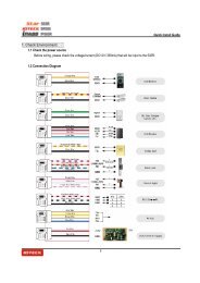
7.1. CHECK POINTS BEFORE <strong>INSTALLATION</strong><br />
7.1.1 SELECTION OF CABLE<br />
System installation cabling will be configured as follow:<br />
Figure: System Installation Layout<br />
17
iTDC/ iTDC-SR/ EIO88<br />
7.1.2 RECOMMENDED CABLE TYPE <strong>AND</strong> PERMISSIBLE LENGTH OF CABLE<br />
Reference Description Cable Specification<br />
1<br />
2 *<br />
3<br />
4<br />
5<br />
6<br />
iTDC Power (DC12V)<br />
DC Power -> iTDC<br />
Reader (Power and Data)<br />
Extra Reader -> iTDC<br />
Door Contact<br />
Exit Button<br />
Sensor Input<br />
Input -> iTDC<br />
Door Lock, Alarm Device<br />
Lock (Alarm) -> iTDC<br />
RS232 Cable<br />
Converter -> Host P.C.<br />
RS485 Cable<br />
iTDC -> iTDC<br />
iTDC -> Converter<br />
RS422 Cable<br />
iTDC -> iTDC<br />
iTDC -> Converter<br />
Belden #9409, 18 AWG<br />
2 conductor, unshielded<br />
Belden #9512, 22 AWG<br />
4 conductor, shielded<br />
Belden #9514, 22 AWG<br />
8 conductor, shielded<br />
Belden #9512, 22 AWG<br />
4 conductor, shielded<br />
Belden #9514, 22 AWG<br />
8 conductor, shielded<br />
Belden #9409, 18AWG<br />
2 conductor, unshielded<br />
Belden #9829, 24 AWG<br />
2-twisted pair, shielded<br />
Belden #9829, 24 AWG<br />
2-twisted pair, shielded<br />
Belden #9830, 24 AWG<br />
3-twisted pair, shielded<br />
*: Requires thicker wire if you connect the reader with high current consumption.<br />
Maximum<br />
Distance<br />
3m<br />
150m<br />
300m<br />
300m<br />
15m<br />
1,200m<br />
7.2 CHECK POINTS DURING <strong>INSTALLATION</strong><br />
7.2.1 TERMINATION RESISTOR<br />
The termination resistors are used to match impedance of the network to the impedance of<br />
the transmission line being used. When impedance is mismatched, the transmitted signal is<br />
not completely absorbed by the receiver and a portion of signal is reflected back into the<br />
transmission line.<br />
The decision whether or not to use termination resistors should be based on the cable length<br />
and the data rate used by the communication system.<br />
For example, if the user uses 9,600 baud rate and 1,200-m length of cable, the propagation<br />
velocity of the cable is 0.66 x speed of light (This value is specified by the cable<br />
manufacturer), if we assume the reflections will damp out in three round trip up and down the<br />
cable length, the transmitted signal will be stabilized 18.6us after the leading edge of a bit.<br />
Since the data bit is captured in the middle of the bit that is approximately 52us after the<br />
leading edge of a bit. The reflection stabilizing time 18.6us is much before the center of the bit<br />
therefore the termination resistors are not required.<br />
However, if the user installs the cable to maximum length, the impedance of the cable and the<br />
network are mismatched and the transmitted signal is overlapped by the reflected signal.<br />
18
iTDC/ iTDC-SR/ EIO88<br />
In this case, it is recommended to add the termination resistors to the end of the receiver lines.<br />
A 120Ω resistor can be used for termination resistor in parallel between the receiver lines “A”<br />
and “B” for 2 wires RS485 system or “RX+” and “RX-” for 4 wires RS422 system. A<br />
termination resistor of less than 90Ω should not be used and no more than 2 termination<br />
resistors should be used in one networking system.<br />
7.2.2 HOW TO CONNECT TERMINATION RESISTORS<br />
Figure: Termination Resistors for 2 Wire RS485 Communication System<br />
Figure: Termination Resistors for 4 Wire RS422 Communication System<br />
7.2.3 GROUNDING SYSTEM FOR COMMUNICATION CABLE<br />
To use such proper grounding system on the communication cable is recommended. The best<br />
method for grounding system is to put the shield wire of the communication cable to the 1 st<br />
class earth grounding; however it is not so easy to bring the earth ground to the<br />
communication cable and also the installation cost is raised.<br />
There will be three grounding points where the user can find during installation;<br />
1) Earth Ground<br />
2) Chassis Ground<br />
3) Power Ground<br />
The most important point for grounding system is not to connect both ends of shield wires to<br />
the grounding system; in this case, there will be a current flow through the shield wire when<br />
the voltage level of both ends of shield wire is not equal and this current flow will create noise<br />
and interfere to communications. For the good grounding, to connect ONLY one end of shield<br />
wire of communication cable to the grounding system is recommended; If the user finds the<br />
earth ground nearby, then connect one end of shield wire to the earth ground; If the user does<br />
not have the earth ground nearby, then find the chassis ground and connect one end of shield<br />
wire to the chassis ground; If the user does not find both earth ground and chassis ground,<br />
then connect one end of shield wire to the power ground. (GND of iTDC)<br />
Please be noticed about that, if the chassis ground is not properly connected to the earth and<br />
19
iTDC/ iTDC-SR/ EIO88<br />
floated from the ground level, then grounding to the chassis ground will give the worst<br />
communication; in this case, to use the power ground instead of chassis ground is<br />
recommended.<br />
Figure: Grounding System<br />
7.2.4 REVERSE DIODE CONNECTION<br />
If the user connects an inductor (Door Locks or Alarm device) to the output relays, there will<br />
be a high surge voltage created while the inductor is turning on and off. If the user does not<br />
connect the reverse diode, the surge voltage will be transferred and damage to the electronic<br />
circuit of the controller. It is strongly recommended to add a reverse diode between the<br />
inductor coils to absorb this surge voltage.<br />
Figure: Reverse Diode Connection<br />
20
8. <strong>INSTALLATION</strong><br />
8.1 DIMENSIONS<br />
Unit: inch (mm)<br />
3.5(90)<br />
5.7(145)<br />
7.3(185)<br />
iTDC DIMENSION<br />
5.3(136)<br />
EIO88 DIMENSION<br />
1.41(36)<br />
1.18(30)<br />
1.97(50)<br />
TCP/IP MODULE DIMENSION<br />
3.15(80)<br />
LCD MODULE DIMENSION<br />
3.15(80)<br />
3.15(80)<br />
7.9(200)<br />
KEYPAD DIMENSION<br />
21
8.2 BOARD ID (COMMUNICATION ID) SETTING<br />
Board ID is the unique board’s address to communicate with the PC. Each board ID on the same<br />
communication loop must be different.<br />
There is an 8 channel DIP switch on the right upper side of the iTDC board for board ID setting. Each<br />
channel of DIP switch has assigned address values and the board ID is the sum value of each switch set to<br />
“ON” position. Board ID can be set from ‘000’ to ‘256’. Refer to the example below.<br />
Caution<br />
If more than one iTDC boards are installing, you must set different Board ID for each<br />
iTDC board. If it is duplicated, the communication error may occur.<br />
Example 1 Example 2 Example 3<br />
1+2 = 3 (Board ID = 3) 4+32 = 36 (Board ID = 36) 128= 128 (Board ID = 128)<br />
Figure: Board ID Setting Example<br />
22
8.3 WIRING<br />
8.3.1 POWER<br />
Connect (+) wire of DC 12V power to +12V terminal<br />
Connect GND (-) wire of DC 12V power to GND terminal<br />
8.3.2 INPUT CONNECTION<br />
Figure: Input Devices Connection<br />
• Exit Button Connection (Input #1, Input #3)<br />
- Connect one wire from an Exit Button to Input #1 for the Door1 and to Input #3 for Door2<br />
- Connect the other wire from the Exit Button to the GND<br />
• Door Contact Sensor Connection (Input #2, Input #4)<br />
- Connect one wire from a Door Contact Sensor to Input #2 for the Door1 and to Input #4 for<br />
Door2<br />
- Connect the other wire from the Door Contact Sensor to GND<br />
• Summary of Input Connections to Corresponding Doors<br />
2-Door Control Door1: Input #1 to Exit Button, Input #2 to Door Contact Sensor<br />
Door2: Input #3 to Exit Button, Input #4 to Door Contact Sensor<br />
23
3-Door Control<br />
Door1: Input #1 to Exit Button, Input #2 to Door Contact Sensor<br />
Door2: EIO88 Input #1 to Exit Button, EIO88 Input #2 to Door Contact<br />
Door3: EIO88 Input #3 to Exit Button, EIO88 Input #4 to Door Contact<br />
Optional EIO88 Expansion I/O Board controls the Exit<br />
Button and Door Contact Sensor for Door 2 and Door 3.<br />
4 Door Control Door1: Input #1 to Exit Button, Input #2 to Door Contact Sensor<br />
Door2: Input #3 to Exit Button, Input #4 to Door Contact Sensor<br />
Door3: EIO88 Input #1 to Exit Button, EIO88 Input #2 to Door Contact<br />
Door4: EIO88 Input #3 to Exit Button, EIO88 Input #4 to Door Contact<br />
Optional EIO88 Expansion I/O Board controls the Exit Button and<br />
Door Contact Sensor for Door 3 and Door 4.<br />
• Auxiliary Input Connection (Applied to Input #5, Input #6 and Input #7)<br />
- Connect one wire from an Auxiliary Input Device to one of the Input #5, #6 and #7.<br />
- Connect the other wire from the Auxiliary Input Device to GND.<br />
※Note: If you have EIO88 Expansion I/O Board, you can use EIO88 Input #5, Input #6,<br />
Input #7 and Input #8 for additional auxiliary input devices.<br />
8.3.3 OUTPUT CONNECTION<br />
Figure: Door Lock, Alarm Device Connection<br />
24
• Door Lock (Power Fail Safe) Connection (Door 1: Relay #1, Door 2: Relay #3)<br />
- Connect COM port of Relay #1 and Relay #3 to +12V<br />
- Connect NC port of Relay #1(Door1) and Relay #3 (Door2) to (+) wire of door lock device<br />
- Connect GND port to (-) wire of door lock devices<br />
•Door Lock (Power Fail Secure) Connection (Door 1: Relay #1, Door 2: Relay #3)<br />
- Connect COM port of Relay #1 and Relay #3 to +12V<br />
- Connect NO port of Relay #1(Door1) and Relay #3 (Door2) to (+) wire of door lock device<br />
- Connect GND port to (-) wire of door lock devices<br />
• Alarm Device Connection (Door1 Alarm: Relay #2, Door2 Alarm: Relay #4)<br />
- Connect COM port of Relay #2 and Relay #4 to +12V<br />
- Connect NO port of Relay #2(Door1) and Relay #4 (Door2) to (+) wire of Alarm devices<br />
- Connect GND port to (-) wire of Alarm devices<br />
• Summary of Output Relay connections to corresponding Doors<br />
2-Door Control Door1: Relay #1 to Door Lock, Relay #2 to Alarm Device<br />
Door2: Relay #3 to Door Lock, Relay #4 to Alarm Device<br />
3-Door Control<br />
Door1: Relay #1 to Door Lock, Relay #2 to Alarm Device<br />
Door2: EIO88 Relay #1 to Door Lock, EIO88 Relay #2 to Alarm<br />
Door3: EIO88 Relay #3 to Door Lock, EIO88 Relay #4 to Alarm<br />
The Door Lock and the Alarm Devices for Door2 and<br />
Door3 are controlled by the optional EIO88 Expansion I/O<br />
Board.<br />
4 Door Control Door1: Relay #1 to Door Lock, Relay #2 to Alarm Device<br />
Door2: Relay #3 to Door Lock, Relay #4 to Alarm Device<br />
Door3: EIO88 Relay #1 to Door Lock, EIO88 Relay #2 to Alarm<br />
Door4: EIO88 Relay #3 to Door Lock, EIO88 Relay #4 to Alarm<br />
The Door Lock and the Alarm Devices for Door3 and<br />
Door4 are controlled by the optional EIO88 Expansion I/O<br />
Board.<br />
Caution<br />
Direction of Diode must be connected as shown on the following figure.<br />
It is recommended to use Fast Recovery DIODE (current: Min. 1A), 1N4001 ~ 1N4007 or<br />
similar<br />
25
Figure: Door Lock, Diode Connection<br />
8.3.4 READER CONNECTION<br />
Figure: Reader Connection<br />
• Proximity Reader Connection<br />
- Connect (+) wire of the Proximity Reader to +12V of Reader port<br />
- Connect (-) wire of the Proximity Reader to GND of Reader port<br />
- Connect Data-0 wire of the Proximity Reader to D0 of Reader Port<br />
- Connect Data-1 wire of the Proximity Reader to D1 of Reader Port<br />
• Summary of Proximity Reader Locations to Corresponding Doors<br />
2-Door Control Door1: Reader #1 to Door1 Entrance, Reader #2 to Door1 Exit<br />
Door2: Reader #3 to Door2 Entrance, Reader #4 to Door2 Exit<br />
26
3-Door Control Door1: Reader #1 to Door1 Entrance, Reader #2 to Door1 Exit<br />
Door2: Reader #3 to Door2 Entrance, Exit Button to Door2 Exit<br />
Door3: Reader #4 to Door3 Entrance, Exit Button to Door3 Exit<br />
The optional EIO88 Expansion I/O Board is necessary to control the Door Locks<br />
and the Exit Buttons for Door2 and Door3.<br />
4 Door Control Door1: Reader #1 to Door1 Entrance, Exit Button to Door1 Exit<br />
Door2: Reader #2 to Door2 Entrance, Exit Button to Door2 Exit<br />
Door3: Reader #3 to Door3 Entrance, Exit Button to Door3 Exit<br />
Door4: Reader #4 to Door4 Entrance, Exit Button to Door4 Exit<br />
The optional EIO88 Expansion I/O Board is necessary to control the Door Locks<br />
and the Exit Buttons for Door3 and Door4.<br />
• Compatible Readers:<br />
iTDC: Standard 26bit Wiegand Format Proximity Readers<br />
Standard 26bit Wiegand + 8bit(or 4bit) Burst Format Proximity and Keypad Readers.<br />
iTDC-SR: Standard 34bit Wiegand Format Proximity Readers<br />
Standard 34bit Wiegand + 8bit(or 4bit) Burst Format Proximity and Keypad Readers.<br />
8.3.5 Control of LEDs and Buzzers of Readers:<br />
You can control the LEDs and Buzzers of the connected readers using the relay outputs of<br />
the iTDC. With IDTECK readers, you can do it by connecting their respective control wire to<br />
GND as instructed below.<br />
• How to Indicate Door Opening Status Using LED of Reader in Power Fail Secure;<br />
You can set the LED of the reader to be lit during the operation of the Door Lock by connecting<br />
the LED Control wire of the Reader to the Relay Output wire between the iTDC and the Door<br />
Lock, as follows;<br />
Figure A: Wiring for LED Indication of Door Opening in Power Fail Secure<br />
27
Caution<br />
CAUTION: If you are using a 24V door lock in a Power Fail Secure configuration,<br />
following the wiring instruction above may cause damage to the Reader. To get around<br />
this problem, you can connect the LED Control wire to the NC terminal of the iTDC<br />
instead to use the other LED color.<br />
• How to Indicate Door Opening Status Using LED of Reader in Power Fail Safe;<br />
After Wiegand connection with the Reader is completed, you can connect the LED Control wire<br />
as described in Figure A (for a Power Fail Secure configuration) or Figure B (for a Power Fail<br />
Safe configuration) to set the Reader to light up the LED during the operation of the Door Lock<br />
Figure B: Wiring for LED Indication of Door Opening in Power Fail Safe<br />
Caution<br />
If you are using separate power sources for the iTDC and the Door Lock, it is advised<br />
to ground each power source properly.<br />
28
8.3.6 OPTIONAL ACCESSORY CONNECTION<br />
Expansion I/O Board Connection (EIO88)<br />
- Connect the EIO88 Expansion I/O Board to iTDC as shown on below.<br />
TCP/IP Module Connection (IIM7100, IIM7100A)<br />
- Connect the IIM7100A TCP/IP Module as shown on below.<br />
EIO88<br />
(EXPANSION I/O BOARD)<br />
TCP/IP module<br />
Keypad and LCD Display Connection<br />
- Connect the Keypad and LCD Display to the Keypad and LCD ports as shown on below.<br />
Keypad<br />
LCD<br />
29
9. COMMUNICATION<br />
9.1 RS232 COMMUNICATION PORT CONNECTION<br />
A 9-pin connector (Serial communication connector, female) is required to connect the iTDC to a<br />
host computer via RS232 communication. Please follow the instructions below;<br />
- Connect RS232-TX port of iTDC to the pin #2 of the 9-pin connector.<br />
- Connect RS232-RX port of iTDC to the pin #3 of the 9-pin connector.<br />
- Connect RS232-GND of iTDC to the pin #5 of the 9-pin connector.<br />
- Plug in the 9-pin connector to COM1 or COM2 Port of the host PC.<br />
- Install and run iTDC Application Software<br />
(STARWATCH iTDC PRO I, II or ST<strong>AND</strong>ARD)<br />
Figure: RS232 Communicaton Cable<br />
9.3 RS-422 COMMUNICATION PORT<br />
9.3.2 RS-422 CONNECTION (ST<strong>AND</strong> ALONE)<br />
RS422/RS232 converter (INC400) is required to use RS422 communication between the<br />
iTDC and a host computer. Please follow the instructions below;<br />
- Connect RS422-TX(+) of the iTDC to RS422-RX(+) port of the converter.<br />
- Connect RS422-TX(-) of the iTDC to RS422-RX(-) port of the converter.<br />
- Connect RS422-RX(+) of the iTDC to RS422-TX(+) port of the converter.<br />
- Connect RS422-RX(-) of the iTDC to RS422-TX(-) port of the converter.<br />
- Plug in the RS232 9-pin connector of the converter to the COM1 or COM2 Port of the PC.<br />
- Install and run the iTDC Application Software.<br />
(STARWATCH iTDC PRO I, II or ST<strong>AND</strong>ARD)<br />
30
Figure: RS422 Communication between iTDC and Host Computer<br />
9.3.3 RS-422 CONNECTION (MULTIPLE iTDC CONNECTIONS)<br />
RS422/RS232 converter is required to use RS422 communication between multiple iTDCs<br />
and a host computer. Please follow the following instructions below;<br />
1 unit of iTDC can use a TCP/IP internal module for communications. And an iTDC used<br />
TCP/IP internal module can communicate with other iTDC Controllers by RS422 method.<br />
In this case, the communication must be connected via RS422 method.<br />
First, you have to connect all RS422 port of all iTDCs in parallel.<br />
- Connect RS422-TX(+) of one iTDC to RS422-TX(+) of another iTDC.<br />
- Connect RS422-TX(-) of one iTDC to RS422-TX(-) of another iTDC.<br />
- Connect RS422-RX(+) of one iTDC to RS422-RX(+) of another iTDC.<br />
- Connect RS422-RX(-) of one iTDC to RS422-RX(-) of another iTDC.<br />
Second, you have to connect one of RS422 port of iTDC to RS422/RS232 converter.<br />
- Connect RS422-TX(+) of the one iTDC to RX(+) port of the converter.<br />
- Connect RS422-TX(-) of the one iTDC to RX(-) port of the converter.<br />
- Connect RS422-RX(+) of the one iTDC to TX(+) port of the converter.<br />
- Connect RS422-RX(-) of the one iTDC to TX(-) port of the converter.<br />
- Plug in the RS232 9-pin connector of the converter to the COM1 or COM2 Port of the PC.<br />
- Install and run iTDC Application Software.<br />
(STARWATCH iTDC PRO I, II or ST<strong>AND</strong>ARD)<br />
31
iTDC/ iTDC-SR/ EIO88<br />
Figure: RS422 Communication between iTDCs and Host Computer<br />
9.4 RS-422 CONNECTION USING THE TCP/IP MODULE (INTERNAL VERSION)<br />
Using an IP (TCP/IP module), multiple iTDCs can communicate with a host computer.<br />
Single unit of main iTDC uses a TCP/IP internal module for LAN communications with the host<br />
computer.<br />
The main iTDC communicates with other iTDC controllers using the RS422 connection.<br />
In this case, iTDCs must be connected via RS422 connection.<br />
Figure: Multi Drop Connection<br />
32
9.4.1 TCP/IP CONVERTER (EXTERNAL VERSION)<br />
When using the TCP/IP converter for communication, select either RS232 or RS422.<br />
Figure: TCP/IP Converter between iTDC and Host PC<br />
INTERFACE iTDC ILAN422 LINE COLOR<br />
TX (CON2) RX (RS232 DSUB9) BLACK+WHITE<br />
RS232 RX (CON2) TX (RS232 DSUB9) RED + WHITE<br />
GND(CON2) GND BLACK<br />
TX+ (CON3) RX+ (RS422 CONNECTOR) GRAY<br />
RS422 TX- (CON3) RX- (RS422 CONNECTOR) YELLOW<br />
RX+ (CON3) TX+ (RS422 CONNECTOR) BROWN<br />
RX- (CON3) TX- (RS422 CONNECTOR) BLUE<br />
10. OPERATION STATUS<br />
10.1 LED INDICATORS OF THE iTDC<br />
The LEDs for indicating the status of the iTDC are located as shown on the Figure: iTDC Board<br />
Layout (12p). Each LED will be turned on and off as the following status of the iTDC.<br />
LED #1 ~ LED#2<br />
These two LEDs indicate the communication status. The LED #1 blinks while the<br />
communication signal is normally being received from the PC. The LED #2 blinks while the<br />
iTDC is sending the signals back to the PC after the data being totally treated as normal. (LED<br />
#1: RXD, LED #2: TXD)<br />
LED #3 ~ LED #6<br />
If the TCP/IP module is installed, these LEDs indicate the status of the TCP/IP module.<br />
LED #3: Connection Status, LED #4: 10M bps, LED #5: 100M bps, LED #6: Communication<br />
Status<br />
LED #7<br />
This LED indicates the status of power supply. The LED is always on if the iTDC is powered on.<br />
33
LED #8 ~ LED #14<br />
These LEDs indicate the status of the Output ports. The LED is turned on while the output is<br />
activated to the output port.<br />
LED #8: Relay #1, LED #9: Relay #2, LED #10: Relay #3, LED #11: Relay #4<br />
LED #12: TTL #1, LED #13: TTL #2, LED #14: TTL #3<br />
LED #15 ~ LED #21<br />
These LEDs indicate the status of the Input ports’ signal. When the LED light is on, it means<br />
that the signal has been input to the input port. (NC type input device) When NO type input<br />
device is connected, the LED is on when the sensor signal is not activated and the LED is off<br />
only when the input is activated.<br />
LED #15: Input #1, LED #16: Input #2, LED #17: Input #3, LED #18: Input #4<br />
LED #19: Input #5, LED #20: Input #6, LED #21: Input #7<br />
10.2 LED INDICATORS OF THE EIO88 EXPANSION I/O BOARD<br />
The LEDs for indicating the status of the EIO88 Expansion I/O Board are located as shown in<br />
the Figure: EIO88 Expansion I/O Board Layout (15p). Each LED will be turned on and off as the<br />
following status of the EIO88 Expansion I/O Board.<br />
LED #17<br />
This LED is for indicating the power status and always on if the EIO88 Expansion I/O Board is<br />
powered on.<br />
LED #1 ~ LED #8<br />
These LEDs indicate the status of the Output ports of EIO88 Expansion I/O Board. The LED is<br />
turned on while the output is activated to the output port.<br />
LED #1: Relay #1, LED #2: Relay #2, LED #3: Relay #3, LED #4: Relay #4<br />
LED #5: Relay #5, LED #6: Relay #6, LED #7: Relay #7, LED #8: Relay #8<br />
LED #9 ~ LED #16<br />
These LEDs indicate the status of the Input ports’ signal. When the LED light is on, it means<br />
that the signal has been input to the input port. (NC type input device) When NO type input<br />
device is connected, the LED is on when the sensor signal is not activated and the LED is off<br />
only when the input is activated.<br />
LED #9: Input #1, LED #10: Input #2, LED #11: Input #3, LED #12: Input #4,<br />
LED #13: Input #5, LED #14: Input #6, LED #15: Input #7, LED #16: Input #8<br />
34
11. BASIC SETTINGS<br />
You have to connect optional LCD display and Keypad to iTDC for the following manual settings.<br />
11.1 INITIALIZATION<br />
Press down the two initialization switches simultaneously and then keep pressing for 2 seconds.<br />
Once buzzer sound is generated, release the two initialization switches then initialization is done<br />
and system restarts automatically.<br />
PRESS<br />
Figure: Position of Initialization Switches<br />
SYSTEM<br />
INITIALIZING...<br />
INITIALIZE END<br />
SYSTEM RESTART<br />
Figure: LCD Display<br />
Caution<br />
If you initialize the iTDC, all the data memories such as ID information, communication<br />
speed, door setting, time schedule and event information stored in the controller will be<br />
cleared and the basic setting values (factory setting values) will be reloaded. Therefore, the<br />
Initialization should be performed by authorized personnel only.<br />
35
11.2 HOW TO ENTER THE SETUP MENU<br />
To set-up or to change the iTDC settings, you have to enter the SETUP MENU first. To do so,<br />
press the 8 times key for Master ID (Default setting “00000000”) and key from the<br />
optional Keypad then you can get into SETUP MENU. There are 4 main SETUP MENU and you<br />
first get into [SETUP MENU F1]. You can move to other SETUP MENU by pressing key<br />
for [SETUP MENU F1], key for [SETUP MENU F2], key for [SETUP MENU F3] and<br />
key for [SETUP MENU F4]. There are several SUB MENU in the main SETUP MENU and<br />
you can scroll up and down the SUB MENU by pressing and key in the main SETUP<br />
MENU. If you don’t press any key for 60 seconds or if you press key then iTDC will exit<br />
the SETUP MENU then return to normal operation. You can also change the Master ID in the<br />
[SETUP MENU F2].<br />
The Master ID for iTDC-SR is 10 times key (Default setting “0000000000”).<br />
11.3 DOOR SETTING<br />
First, you have to configure “How many doors you want to control by iTDC”, as the iTDC will<br />
automatically configure the Input sources and Output Relays upon to the number of doors to be<br />
controlled by iTDC. Press key once then press key or key until the LCD shows<br />
[DOOR SETTING] in the [SETUP MENU F2] then press key to change the DOOR<br />
SETTING. Please follow the steps below for DOOR SETTING and it shows the procedure for 4<br />
DOOR SETTING.<br />
The Master ID for iTDC-SR is 10 digits number (Default setting “0000000000”).<br />
STAR iTDC [F1]<br />
01/01 00:00:15<br />
Initial LCD Display<br />
“MASTER ID” + <br />
8 times + <br />
Press + 7times <br />
Select [DOOR SETTING]<br />
+ <br />
8. DOOR SETTING<br />
2 DOOR<br />
<br />
8. DOOR SETTING<br />
->2 DOOR<br />
or<br />
<br />
8. DOOR SETTING<br />
->4 DOOR<br />
<br />
8. DOOR SETTING<br />
4 DOOR<br />
4 DOOR Setting Completed<br />
36
11.4 DATE <strong>AND</strong> TIME SETTING<br />
Select [TIME SETTING] in the [SETUP MENU F2] and enter the Year / Month / Date / hour /<br />
minute / second / Day (Total 15 digits) as shown below. LCD will display the new Date and Time<br />
after the time setting completed but year and day will not be displayed. iTDC has 24 hours<br />
system and day codes are 1 for Sunday, 2 for Monday, 3 for Tuesday, 4 for Wednesday, 5 for<br />
Thursday, 6 for Friday and 7 for Saturday.<br />
The Master ID for iTDC-SR is 10 digits number (Default setting “0000000000”).<br />
STAR iTDC [F1]<br />
01/01 00:00:15<br />
Initial Display<br />
“MASTER ID” + <br />
8 times + <br />
Press <br />
Select [TIME SETTING]<br />
+ <br />
1. TIME SETTING YYYYMMDDhhmmssW<br />
<br />
200910192003302<br />
<br />
“Year/Month/Day/Hour/Min./Sec./Day”<br />
1. TIME SETTING<br />
10/19 20:03:30<br />
<br />
STAR iTDC [F1]<br />
10/19 20:03:30<br />
LCD displays after time setting<br />
11.5 MAXIMUM USER SETTING<br />
iTDC can register maximum 50,000 user IDs and you can select maximum user ID to be<br />
registered into the iTDC from 1,000 to 20,000 users in 1,000 increments. This MAX USER SET<br />
is to configure maximum user ID to be registered into iTDC. The default ID COUNT is 5,000<br />
Users and the default EVENT Buffer size is 27,500 can be stored when you operate iTDC .<br />
Select [MAX USER SET] in the [SETUP MENU F3] then set-up the maximum User ID to be<br />
registered into iTDC. Follow the steps to set-up ID COUNT.<br />
The Master ID for iTDC-SR is 10 digits number (Default setting “0000000000”).<br />
STAR iTDC [F1]<br />
01/20 09:00:33<br />
Initial Display<br />
“MASTER ID” + <br />
8 times + <br />
37<br />
Press + or <br />
Select [5.MAX USER SET]
5.MAX USER SET<br />
05000<br />
<br />
ENTER ID COUNT<br />
[20000]<br />
<br />
Enter the number from 1000 to 50000<br />
5.MAX USER SET<br />
20000<br />
<br />
STAR iTDC [F1]<br />
01/20 09:01:16<br />
EVENT MEMORY<br />
NOT EMPTY !!!<br />
☞ This error message will be displayed when you press<br />
key in the [MAX USER SET] menu and it<br />
means that some events are still existing in the<br />
EVENT Buffer and you may lost the data when you<br />
change the MAX USER SET. You may try this setting<br />
again after uploading the events to the host PC or<br />
deleting them, using the [SETUP MENU F2] -><br />
[EVENT CLEAR].<br />
INVALID NUMBER<br />
☞ This error message will be displayed when you try to<br />
change MAX USER SET less than the total registered<br />
User ID. In this case you have to delete some User ID<br />
or clear the User ID, using the [SETUP MENU F2] -><br />
[ID CLEAR] first then try again from the beginning.<br />
38
11.6 ID REGISTRATION<br />
You can register the User ID into the iTDC. Select [SETUP MENU F3] -> [ID REG.] then follow<br />
the steps below:<br />
The Master ID for iTDC-SR is 10 digits number (Default setting “0000000000”).<br />
STAR iTDC [F1]<br />
01/20 09:01:23<br />
Initial LCD Display<br />
“MASTER ID” + <br />
8 times + <br />
Press then<br />
Select<br />
[ID REGISTRATION]<br />
1. ID REG.<br />
<br />
ID [________]<br />
PW [____] CODE_<br />
ID (8digits) + <br />
Password (4digits) + <br />
Code (1digit) + <br />
TA__TB__TC__TD__<br />
RA_ RB_ RC_ RD_<br />
Time Schedule codes + <br />
Reader Usage codes + <br />
TA00TB00TC00TD00<br />
ID Registered<br />
Reg. completed<br />
1. ID [________]: ID number consists of 3-digits Facility code from 000 to 255 and 5-digits ID<br />
number from 00000 to 65535 so that the 8-digits ID number cannot exceed 25565535. If you<br />
don’t know the ID number of the proximity cards then select [SETUP MENU F4] -> [READER<br />
TEST] then present the card to the reader to display the ID number. Enter 8-digits ID number<br />
then press key in the ID [________] field. (ID number of iTDC-SR has 10-digit number.)<br />
2. PW [____]: PW is the password which can be used to access the doors where you install a<br />
Proximity and Keypad Reader and set-up the RF + Password operating mode. But regardless of<br />
the operating mode, it is necessary to enter a default password (0000) in the PW [____] field<br />
when you register ID.<br />
3. CODE_: CODE is to enter ID type. Individual ID is distinguished by “0” for general user (0),<br />
“1” for 2 men operation then group #1 ID (1), “2” for 2 men operation then group #2 ID (2) or “3”<br />
for special ID (3) who can set “arm / disarm function” or “2 level individual door opening time<br />
setting”.<br />
39
1 [TWO MEN MODE]: “NOTUSE” / [ARM/DISARM CODE]: “00”<br />
The group #1 ID (1) and group #2 ID (2) perform same operation with general user (0).<br />
The special ID (3) occurs settings of [READER DEFINE] / 17.R1 SPECIAL ID ~ 20. R4<br />
SPECIAL ID in [SETUP MODE F2].<br />
2 [TWO MEN MODE]: “NOTUSE” / [ARM/DISARM CODE]: Any 2digit no. (except “00”)<br />
The group #1 ID (1) and group #2 ID (2) perform same operation with general user.<br />
The special ID (3) is used to set “ARM/DISARM ”. But the special ID (3) is used as<br />
general user (0) if the special ID (3) is authorized to the iTDC /iTDC-SR with not entering<br />
“ARM/DISARM CODE”.<br />
3 [TWO MEN MODE]: “USE” / [ARM/DISARM CODE]: “00”<br />
Make sure that make the group #1 ID (1) and the group #2 (2) present. If you so, the<br />
iTDC/iTDC-SR permits to access of two group IDs. The special ID (3) occurs settings of<br />
[READER DEFINE] / 17.R1 SPECIAL ID ~ 20. R4 SPECIAL ID in [SETUP MODE F2].<br />
4 [TWO MEN MODE]: “USE” / [ARM/DISARM CODE]: Any 2digit no. (except “00”)<br />
Make sure that make the group #1 ID (1) and the group #2 (2) present. If you so, the<br />
iTDC/iTDC-SR permits to access of two group IDs.The special ID (3) is used to set<br />
“ARM/DISARM ”. But the special ID (3) is used as general user (0) if the special ID (3) is<br />
authorized to the iTDC / iTDC-SR with not entering “ARM/DISARM CODE”. To use<br />
general access control system, you must input “0” for all users.<br />
4. TA__TB__TC__TD__: TA, TB, TC and TD are Time Schedule code (00-15) for the Readers,<br />
TA is the Time Schedule for the Reader #1, TB is for Reader #2, TC is for Reader #3 and TD is<br />
for Reader #4. When you present the card to Reader #1 then the cardholder is only allowed the<br />
access of the door during the Time Schedule code entered to TA__ and the other Readers are<br />
the same manner. To control the accessible Time Schedule for each cardholder, you must set-up<br />
the Time schedules first and enter the Time Schedule code here. If you want to access the door<br />
anytime for the cardholder then enter default Time Schedule code '00' for the value.<br />
5. RA__RB__RC__RD__: RA, RB, RC and RD are Reader Usage codes for the cardholder. If<br />
you put ‘1’ for RA then Reader #1 is accessible and if you put ‘0’ for RA then the cardholder<br />
cannot access through the Reader #1 and iTDC generates an error message “Access Door<br />
Error” and displays on the LCD. To get access through all 4 Readers, you have to input ‘1’ value<br />
for RA, RB, RC and RD.<br />
11.7 OUTPUT SETTING<br />
You can program the output operation by the iTDC application software (STARWATCH iTDC<br />
PRO I, II or ST<strong>AND</strong>ARD). Please refer to APPENDIX for Default setting values.<br />
40
12. OPERATION<br />
12.1 NORMAL OPERATION<br />
Power on<br />
When the power is applied to iTDC, the LED #7 is turned on.<br />
Registered card reading<br />
When a registered card (or PIN) is read, the Door (Relay #1, Relay #3) will open for 3 seconds<br />
(Default) with the LED on. (LED #8, LED #10)<br />
Exit Button<br />
To exit from the inside, an Exit Button (or an Exit Reader) can be used.<br />
The Door (Relay #1, Relay #3) will open for 3 seconds with the LED on. (LED #8, LED #10)<br />
Alarms<br />
When an unregistered card is read, the access is denied and the alarm (Relay #2, Relay #4)<br />
will be activated for 3 seconds with the LED on (LED #9, LED #11) along with the buzzer<br />
sound.<br />
12.2 DEFAULT SETTING<br />
When you operate the iTDC first time or you initialize the iTDC, the controller will set-up all<br />
values to defaults (factory settings). You can change the settings for desired application.<br />
Please refer to the 14.APPENDIX (75p) for the default setting values.<br />
41
iTDC/ iTDC-SR/ EIO88<br />
13. SETTING CHANGES<br />
INITIAL DISPLAY<br />
(MODEL NAME, CURRENT TIME)<br />
NO<br />
ID INPUT ?<br />
YES<br />
MASTER ID ?<br />
YES<br />
NO<br />
NORMAL OPERATION<br />
MODE<br />
SETUP MENU<br />
SETUP MENU F1<br />
SETUP MENU F2<br />
SETUP MENU F3<br />
SETUP MENU F4<br />
1. READER 1 MODE<br />
2. READER 2 MODE<br />
3. READER 3 MODE<br />
4. READER 4 MODE<br />
5. DOOR 1 APB<br />
6. DOOR 2 APB<br />
7. RD1 KEY IN<br />
8. RD2 KEY IN<br />
9. RD3 KEY IN<br />
10. RD4 KEY IN<br />
11. RD1 DURESS<br />
12. RD2 DURESS<br />
13. RD3 DURESS<br />
14. RD4 DURESS<br />
15. RD1 T/S<br />
16. RD2 T/S<br />
17. RD3 T/S<br />
18. RD4 T/S<br />
19. R1 OPEN CHECK<br />
20. R2 OPEN CHECK<br />
21. R3 OPEN CHECK<br />
22. R4 OPEN CHECK<br />
1. TIME SETTTING<br />
2. HOLIDAY INDEX<br />
3. COMM ID<br />
4. BAUD RATE<br />
5. MASTER ID REG<br />
6. EVENT SAFE<br />
7. DOOR ALARM<br />
8. DOOR SETTING<br />
9. HOLIDAY SET.<br />
10. TIME SCHEDULE<br />
11. IN/OUT DEFINE<br />
12. READER DEFINE<br />
13. SYSTEM INIT.<br />
14. EVENT CLEAR<br />
15. CARD ID CLEAR<br />
16. T/S CLEAR<br />
1. ID REG.<br />
2. ID DELETE<br />
3. ID LIST<br />
4. REG. ID COUNT<br />
5. MAX USER SET<br />
6. EVENT COUNT<br />
7. KEY INPUT MODE<br />
8. ARM/DIS. CODE<br />
9. ARM/DIS. INPUT<br />
10. TWO MEN MODE<br />
11. INPUT TS MODE<br />
1. VERSION<br />
2. RAM TEST<br />
3. OUTPUT TEST<br />
4. LCD TEST<br />
5. KEYPAD TEST<br />
6. READER TEST<br />
7. INPUT TEST<br />
8. COMM TEST<br />
☞. To set-up or to change the iTDC settings, you have to enter the SETUP MENU<br />
first. To do so, press 8 times key for Master ID (Default setting “00000000”)<br />
and key from the optional Keypad then you can get into SETUP MENU.<br />
There are 4 main SETUP MENU and you first get into [SETUP MENU F1]. You<br />
can move to other SETUP MENU by pressing key for [SETUP MENU F1],<br />
key for [SETUP MENU F2], key for [SETUP MENU F3] and key<br />
for [SETUP MENU F4]. There are several SUB MENU in the main SETUP MENU<br />
and you can scroll up and down the SUB MENU by pressing and key in<br />
the main SETUP MENU. If you don’t press any key for 20 seconds or if you press<br />
key then iTDC will exit the SETUP MENU then return to normal operation.<br />
The Master ID for iTDC-SR is 10 times key (Default setting “0000000000”).<br />
42
13.1 SETUP MENU F1<br />
iTDC/ iTDC-SR/ EIO88<br />
Searching key<br />
or <br />
1. READER 1 MODE<br />
key or <br />
2. READER 2 MODE<br />
key or <br />
3. READER 3 MODE<br />
key or <br />
4. READER 4 MODE<br />
key or <br />
5. DOOR 1 APB<br />
key or <br />
RF Only (default)<br />
RF+PASSWORD<br />
RF Only (default)<br />
RF+PASSWORD<br />
RF Only (default)<br />
RF+PASSWORD<br />
RF Only (default)<br />
RF+PASSWORD<br />
NOT USE (default)<br />
USE(ALONE)<br />
USE(ZONE)<br />
ALL CLEAR<br />
6. DOOR 2 APB<br />
key or <br />
NOT USE (default)<br />
USE(ALONE)<br />
USE(ZONE)<br />
ALL CLEAR<br />
7. RD1 KEY IN<br />
key or <br />
8. RD2 KEY IN<br />
key or <br />
9. RD3 KEY IN<br />
key or <br />
DISABLE (default)<br />
ENABLE<br />
DISABLE (default)<br />
ENABLE<br />
DISABLE (default)<br />
ENABLE<br />
43
10. RD4 KEY IN<br />
DISABLE (default)<br />
ENABLE<br />
key or <br />
11. RD1 DURESS<br />
key or <br />
NOT USE (default)<br />
USE<br />
DURESS 1 P/W<br />
12. RD2 DURESS NOT USE (default)<br />
USE<br />
key or <br />
DURESS 2 P/W<br />
13. RD3 DURESS<br />
key or <br />
NOT USE (default)<br />
USE<br />
DURESS 3 P/W<br />
Searching key<br />
or <br />
14. RD4 DURESS NOT USE (default)<br />
USE<br />
key or <br />
DURESS 4 P/W<br />
15. RD1 T/S<br />
22 Digit number<br />
key or <br />
16. RD2 T/S 22 Digit number<br />
key or <br />
17. RD3 T/S<br />
22 Digit number<br />
key or <br />
18. RD4 T/S<br />
22 Digit number<br />
44
Searching key<br />
or <br />
19.R1 OPEN CHECK<br />
Key or <br />
20.R2 OPEN CHECK<br />
Key or <br />
21.R3 OPEN CHECK<br />
Key or <br />
22.R4 OPEN CHECK<br />
NOT USE (default)<br />
USE<br />
NOT USE (default)<br />
USE<br />
NOT USE (default)<br />
USE<br />
NOT USE (default)<br />
USE<br />
* R2 OPEN CHECK, R3 OPEN CHECK and R4 OPEN CHECK is the same as above.<br />
13.1.1 READER MODE SETTING<br />
READER 1 MODE<br />
<br />
RF ONLY (default)<br />
Seaching key or <br />
RF+PASSWORD<br />
1.READER1 MODE<br />
RF ONLY<br />
1.READER1 MODE<br />
->RF ONLY<br />
1.READER1 MODE<br />
->RF+PASSWORD<br />
☞. It shows READER1 MODE is set to RF ONLY operating<br />
mode. If you want to change the mode to RF+PASSWORD<br />
operating mode, press key.<br />
☞. Now you can change the mode by pressing or key to<br />
toggle the mode. If you want to set-up the mode displayed<br />
then press key to accept this mode.<br />
RF ONLY: The door is accessible with the proximity card<br />
alone.<br />
RF+PASSWORD (4 digit number): The door is accessible<br />
with the proximity card and Password.<br />
* READER2, READER3 and READER4 MODE set-up is the same as above.<br />
45
13.1.2 ANTI-PASS-BACK MODE SETTING<br />
5.DOOR 1 APB<br />
NOT USE<br />
5.DOOR 1 APB<br />
->USE(ALONE)<br />
5.DOOR 1 APB<br />
->USE(ZONE)<br />
☞. It shows DOOR1 anti-pass-back operation is not used. Press<br />
key. (It is only applied when the Door has Exit Reader)<br />
For Door1 (2), you must have Reader #1(#2) for entry and<br />
Reader #3 (#4) for exit.<br />
☞. Press or key for searching the APB mode.<br />
Press key to select the mode.<br />
NOT USE: Anti-pass-back mode is not applied.<br />
USE (ALONE): Door1 (2) Anti-pass-back mode is separately<br />
applied.<br />
USE (ZONE): Door1 (2) Anti-pass-back mode is applied<br />
together.<br />
Note: If you select USE (ZONE) then the APB flag will be<br />
affected to Door1 and Door2. DOOR2 APB mode is set<br />
automatically.<br />
Example: When you select USE (ALONE) then Door2 entry is<br />
possible after you got in through Door1. When you select USE<br />
(ZONE) then Door2 entry is not possible after you got in<br />
through Door1. (APB error)<br />
5.DOOR 1 APB<br />
->All CLEAR<br />
☞. If you select ALL CLEAR then iTDC will clear all APB flags and<br />
all users are allowed to enter or exit once regardless of access<br />
status.<br />
* DOOR2 APB mode set-up is the same as above.<br />
13.1.3 KEYPAD INPUT SETTING<br />
7.RD1 KEY IN<br />
DISABLE<br />
7.RD1 KEY IN<br />
->ENABLE<br />
☞. This function is to set DISABLE/ENABLE the keypad inputs<br />
from the Proximity and Keypad Readers. The default setting is<br />
DISABLE. If you install Keypad Reader (8bit burst format) and<br />
set this mode ENABLE, you can access the Door by pressing<br />
8digit User ID from the keypads.<br />
Press key and press or key to select<br />
->ENABLE then press key to set-up this function.<br />
* READER2, READER3 and READER4 KEY IN set-up is the same as above.<br />
46
13.1.4 DURESS MODE SETTING<br />
READER 1 DURESS<br />
<br />
<br />
NOT USE(default)<br />
Searching key or <br />
USE<br />
<br />
DURESS 1 P/W<br />
<br />
<br />
ENTER NEW P/W<br />
(2digit + )<br />
11.RD1 DURESS<br />
NOT USE<br />
11.RD1 DURESS<br />
-> USE<br />
DURESS 1 P/W<br />
00<br />
☞. You can select whether the DURESS mode is used or not used<br />
for READER1. To use this function, you need Keypad Reader.<br />
Default setting is NOT USE. If you want to set-up Duress mode<br />
then press key and select ->USE by pressing or<br />
key then press key. LCD will display default Duress<br />
Password ‘00’. Press key again to enter 2 digit Duress<br />
Password then press key to finish setting.<br />
Note: In case of Duress, enter the 2 digit Duress Password and<br />
key then present the card. Door will be opened as<br />
normal but the Duress alarm will be generated and reported to<br />
the host PC.<br />
DURESS 1 P/W<br />
00<br />
* READER2, READER3 and READER4 DURESS set-up is the same.<br />
47
13.1.5 READER TIME SCHEDULE SETTING<br />
15.RD1 T/S<br />
00<br />
15.RD1 T/S<br />
00<br />
☞. If you set-up RF+PASSWORD operating mode for Reader #1<br />
(Refer to READER1 MODE SETTING), you can apply Time<br />
Schedule for Reader #1. During the time period of Time Code<br />
in the T/S, Reader #1 will operate RF ONLY mode. And the rest<br />
of time period, Reader #1 will operate RF+PASSWORD mode.<br />
To apply this function, you have to set-up Time Schedules<br />
(T/S) and Holiday Schedules (H/S) from the iTDC Application<br />
Software and download T/S with H/S index to the iTDC. Please<br />
refer to iTDC Software Manual for detail.<br />
Select READER1 T/S then press key. Enter 2 digit T/S<br />
index (‘00’ ~ ‘15’) then press key to apply it.<br />
* READER2, READER3 and READER4 T/S set-up is the same as above.<br />
13.1.6 READER OPEN CHECK SETTING<br />
19.R1 OPEN CHECK<br />
NOT USE<br />
19.R1 OPEN CHECK<br />
USE<br />
☞. You should set to check whether Reader#1 (R1) is<br />
opened or not.<br />
Default is “NOT USE”.<br />
☞. You can change the setting by pressing “4” or “6” key.<br />
After changing the setting, press key if the setting<br />
is completed.<br />
NOT USE : In case of “NOT USE”, it doesn’t confirm to<br />
check about R1 (Reader#1) OPEN.<br />
USE (ALONE) : When R1 (Reader#1) is open, the iTDC<br />
sounds beeper and makes event occur. In result, you can<br />
confirm status on the PC.<br />
READER OPEN STATUS:<br />
The reader outputs “00000000” through reader’s data wire<br />
once within 60sec. At this time, if “00000000” is transmitted<br />
by the reader in the iTDC, the unit judges that reader is<br />
normally connected. Therefore you can know connection<br />
status of reader without additional wiring.<br />
* R2 OPEN CHECK, R3 OPEN CHECK and R4 OPEN CHECK is the same as above.<br />
48
13.2 SETUP MENU F2<br />
1.TIME SETTING<br />
15 Digit key in<br />
key or <br />
2.HOLIDAY INDEX<br />
key or <br />
Setup each T/S index<br />
(2 Digit)<br />
3.COMM ID<br />
Display communication ID<br />
Searching key<br />
or <br />
key or <br />
4.BAUD RATE<br />
key or <br />
4800<br />
9600(default)<br />
19200<br />
38400<br />
5.MASTER ID REG.<br />
KEY ( 8 digit )<br />
key or <br />
6.EVENT MEMORY<br />
key or <br />
USE (default)<br />
NOT USE<br />
7.DOOR ALARM<br />
2 Digit ( default 3 second )<br />
key or <br />
8.DOOR SETTING<br />
key or <br />
2 DOOR(default)<br />
3 DOOR<br />
4 DOOR<br />
9.HOLIDAY SETTING<br />
INDEX : 01 ~ 10<br />
No.: 01 ~ 100<br />
49
Searching key<br />
or <br />
10.TIME SCHEDULE<br />
key or <br />
11.IN/OUT DEFINE<br />
key or <br />
12.READER DEFINE<br />
key or <br />
13.SYS INITIALIZE<br />
key or <br />
14.EVENT CLEAR<br />
key or <br />
15.CARD ID CLEAR<br />
key or <br />
16.TIME SCHE CLEAR<br />
INDEX : 01 ~ 15<br />
WEEKLY: HOL, SUN…SAT<br />
No.: 01 ~ 05<br />
01 ~ 07: INPUT #1 ~ #7<br />
08 ~ 15: EIO INPUT #1 ~ #8<br />
16 ~ 19: DURESS MODE #1 ~#4<br />
20: OUTPUT T/S<br />
21: INPUT T/S<br />
22: INPUT TYPE<br />
23 ~ 26: DR TIME OUT 1 ~ 4<br />
01: 01: R1 R1 ID OK ID OK<br />
02: 02: R1 R1 ID ERROR ID ERROR<br />
03: 03: R1 R1 ID T/S ID T/S ERROR ERROR<br />
04: 04: R1 R1 APB APB ERROR ERROR<br />
05: 05: R2 R2 ID OK ID OK<br />
06: 06: R2 R2 ID ERROR ID ERROR<br />
07: 07: R2 R2 ID T/S ID T/S ERROR ERROR<br />
08: 08: R2 R2 APB APB ERROR ERROR<br />
09: 09: R3 R3 ID OK ID OK<br />
10: 10: R3 R3 ID ERROR ID ERROR<br />
11: 11: R3 R3 ID T/S ID T/S ERROR ERROR<br />
12: 12: R3 R3 APB APB ERROR ERROR<br />
13: 13: R4 R4 ID OK ID OK<br />
14: 14: R4 R4 ID ERROR ID ERROR<br />
15: 15: R4 R4 ID T/S ID T/S ERROR ERROR<br />
16: 16: R4 R4 APB APB ERROR ERROR<br />
17: 17: R1 R1 SPECIAL ID ID<br />
18: 18: R2 R2 SPECIAL ID ID<br />
19: 19: R3 R3 SPECIAL ID ID<br />
20: 20: R4 R4 SPECIAL ID ID<br />
YES<br />
NO<br />
YES<br />
NO<br />
YES<br />
NO<br />
YES<br />
NO<br />
* Please refer to 14. Appendix on this manual (75p) for default values.<br />
50
iTDC/ iTDC-SR/ EIO88<br />
13.2.1 TIME SETTING<br />
1.TIME SETTING<br />
10/19 20:43:10<br />
YYYYMMDDhhmmssW<br />
_ _ _ _ _ _ _ _ _ _<br />
☞. Press key and enter 15 digit Date/Time codes then<br />
key to finish setting.<br />
YYYY: Year, MM: Month, DD: Date<br />
hh: Hours (24 hours system), mm: Minutes, ss: Seconds<br />
W: Sun=1, Mon=2, Tue=3, Wed=4, Thu=5, Fri=6, Sat=7<br />
Example: 200902101330152 => Feb.10, 2009 13:30:15 Mon<br />
13.2.2 HOLIDAY INDEX SETTING<br />
2.HOLIDAY INDEX<br />
T/S_INDEX 01<br />
HOLIDAY CODE 00<br />
☞. Holiday Index is to link the Holiday Schedule (H/S) to Time<br />
Schedule. You can set-up one of holiday index (01~10) to one<br />
of T/S index (01~15) so that the Holiday Time Code in the T/S<br />
can be applied for the Holidays in the H/S. Default HOLIDAY<br />
CODE is ‘00’ which means no holidays are applied to T/S.<br />
Select HOLIDAY INDEX menu and press then select<br />
desired T/S_INDEX (01~15) by pressing or key then<br />
press key to input 2 digit HOLIDAY CODE and<br />
.<br />
13.2.3 COMMUNICATION ID (ADDRESS) DISPLAY<br />
3.COMM ID<br />
000<br />
☞. This menu shows the current communication ID of the iTDC.<br />
If multiple iTDC units are connected to one host PC, each<br />
unit must be configured to different communication ID.<br />
Note: You can change COMM ID by DIP switch setting of the<br />
iTDC.<br />
13.2.4 BAUD RATE SETTING<br />
4.BAUD RATE<br />
9600<br />
4.BAUD RATE<br />
->9600<br />
4.BAUD RATE<br />
->19200<br />
☞. iTDC supports 4800, 9600, 19200 and 38400bps of baud rate<br />
and default setting are 9600bps. Wrong baud rate setting will<br />
cause communication errors and you have to set same baud<br />
rate to iTDC and host PC. If you have communication<br />
problem, please check followings;<br />
- Check COMM ID of iTDC and host PC<br />
- Check BAUD RATE of iTDC and host PC<br />
- Check communication port and cable<br />
- Check COM port set-up of host PC<br />
Parity Bit: None, Data Bit: 8 bit, Stop Bit: 1 bit<br />
To change the baud rate, press key and select desired<br />
baud rate by pressing or key then press key.<br />
51
iTDC/ iTDC-SR/ EIO88<br />
13.2.5 MASTER ID CHANGE<br />
5.MASTER ID REG<br />
☞. Press key to change the current Master ID (“00000000”).<br />
You should use the new Master ID to access the SETUP MENU<br />
after you changed the Master ID.<br />
5.MASTER ID REG<br />
[________]<br />
☞. You should use 8 digits number for Master ID. Press key<br />
and enter the new 8 digits Master ID and key.<br />
MASTER CARD<br />
REGISTERED<br />
☞. Master ID is now changed and stored in the memory.<br />
LCD shows new Master ID is registered successfully.<br />
The Master ID for iTDC -SR is 10 digits number (Default setting “0000000000”).<br />
13.2.6 EVENT MEMORY SETTING<br />
6.EVENT SAFE<br />
USE<br />
6.EVENT SAFE<br />
->NOT USE<br />
☞. You can select whether you use event memory or not. When you<br />
select USE and in case of event memory full then iTDC<br />
generates an error message and keeps all events stored in the<br />
memory. When you select NOT USE then iTDC will not<br />
generate an error and new event overwrite into the event<br />
buffers. If you use iTDC for standalone (just for door access)<br />
then select NOT USE.<br />
13.2.7 DOOR OPEN ALARM SETTING<br />
7.DOOR ALARM<br />
03<br />
7.DOOR ALARM<br />
99<br />
☞. When the door is still opened after the door unlock time, you<br />
may set this alarm function. To use this function, you have to<br />
install Door Contact Sensor on the door and set-up the output of<br />
Door Contact Sensor from the iTDC Application Software. ‘03’ is<br />
default.<br />
00: Alarm if the door is opened after the door unlock time<br />
01~98: Alarm if the door is opened after the set time (01~98s)<br />
99: No alarm<br />
13.2.8 DOOR SETTING<br />
8.DOOR SETTING<br />
2 DOOR<br />
8.DOOR SETTING<br />
->2 DOOR<br />
☞. Set-up how many doors to be controlled by the iTDC.<br />
2 DOOR: Reader#1-Door1 Entry, Reader#2-Door1 Exit<br />
Reader#3-Door2 Entry, Reader#4-Door2 Exit<br />
3 DOOR: Reader #1-Door1 Entry, Reader #2-Door1 Exit<br />
Reader#3-Door2 Entry, Reader#4-Door3 Entry<br />
4 DOOR: Reader#1, #2, #3, #4-Door1, 2,3,4 Entry<br />
Note: Door setting must be set-up first before other set-up.<br />
Please refer to section 8.3 DOOR SETTING.<br />
52
13.2.9 HOLIDAY SETTING<br />
HOLIDAY SET<br />
<br />
DISPLAY CURRENT T/S<br />
SELECT T/S NUMBER <strong>AND</strong> INDEX<br />
(USE '2','8','4','6' KEY)<br />
<br />
ENTER T/S(4 DIGIT)<br />
(MM:DD)<br />
NO<br />
or ‘ESC’<br />
NEXT?<br />
YES<br />
or Error<br />
9.HOLIDAY SET<br />
☞. You can register up to 100 specified holidays per year for each<br />
schedule setting. There can be 10 other registration sets<br />
created, meaning holidays can be set for up to 10 years.<br />
Press to register the days.<br />
HOL TS: 01 #001<br />
00/00<br />
☞. With the key and key, select the Date Registration<br />
Set Number (1~10), and with the key and key, select<br />
the index for the days (1~100). Press key and the<br />
cursor will blink. Enter the date, in form of the Month (1~12).<br />
The LCD will indicate the defined date. Now a day has been<br />
registered. For further registration, repeat the process.<br />
☞. 1) Holiday Time schedule (Date registration set) number: 01 ~ 10(10 years)<br />
2) Index for the days: 01 ~ 100(100 days)<br />
53
13.2.10 TIME SCHEDULE SETTING<br />
iTDC/ iTDC-SR/ EIO88<br />
TIME SCHEDULE<br />
<br />
DISPLAY CURRENT T/S<br />
SELECT T/S NUMBER <strong>AND</strong> INDEX<br />
(USE '2','8','4','6' KEY)<br />
<br />
ENTER T/S(8 DIGIT)<br />
(START TIME(hh:mm)-END TIME(hh:mm))<br />
NO<br />
or <br />
NEXT?<br />
YES or<br />
Error<br />
10.TIME SCHEDULE<br />
T/S: 01 HOL #1<br />
00:00 - 00:00<br />
☞. You may program time schedules to grant and restrict access<br />
for each user. There can be up to 15 different schedules.<br />
Minimum of one schedule must be defined.<br />
If only one schedule is programmed the most common setting<br />
allows access for all users 24 hours / day. A time schedule<br />
can be programmed for each day of the week and holidays,<br />
and five shifts can be defined for each day. To set time<br />
schedules, press key from this menu.<br />
If you want to set time schedules, press key when this<br />
figure is displayed.<br />
☞. Press key or key to adjust the Time Schedule (T/S)<br />
number (1-15) and the day of the week (Mon-Sun and ‘HOL’).<br />
Define which shift of the day (1-5), using the key and <br />
key. ‘HOL’ refers to specific holidays you will register. Press<br />
key, and the cursor will blink, then enter the beginning<br />
time of the period, in the form of hour (2-digit): minute (2-digit)<br />
and the ending time in the same form. Then the lower line will<br />
indicate the defined period. For more schedules, repeat the<br />
process. To end time scheduling, press key.<br />
☞. Possible values for time scheduling<br />
1) Time schedule number: 01 ~ 15 (Needed when IDs are registered)<br />
2) A day of the week: MON, TUE, WED, THU, FRI, SAT, SUN, HOL<br />
3) Index: 1 ~ 5 (1 Day is divided and set to 5 sections)<br />
54
13.2.11 DEFINING OUTPUT TIME IN COMPLIANCE WITH INPUTS<br />
iTDC/ iTDC-SR/ EIO88<br />
IN/OUT DEFINE<br />
<br />
DISPLAY CURRENT SET<br />
SELECT INDEX<br />
(USE '4','6' KEY)<br />
<br />
ENTER NEW TIME OR INDEX FOR ITDC<br />
(14 DIGIT OR EVEN DIGIT) + <br />
NEXT?<br />
YES or<br />
Error<br />
11.IN/OUT DEFINE<br />
☞. You can program or deactivate each output to be generated<br />
and choose how long (in seconds) they will last. There are<br />
default values as seen in the 14. APENDIX (A. THE<br />
RELATION BETWEEN INPUT <strong>AND</strong> OUTPUT (DEFAULT)<br />
1.iTDC INPUT #1<br />
☞. Select input sources by changing Index numbers with the keys<br />
or .<br />
iTDC: 03 00 00<br />
00 00 00 00<br />
☞. Press key and you will see a cursor blinking at the first<br />
digit from the left of the seven couples of digits (Output of<br />
iTDC). Enter the 14 digit (seven couples) key.<br />
EIO: 00 00 00<br />
00 00 00 00 00<br />
☞. Press key and you will see a cursor blinking at the first<br />
digit from the left of the eight couples of digits (Output of<br />
EIO88). To set time for eight couples, press key. For<br />
more inputs, repeat the process. To end input setting, press<br />
key.<br />
55
13.2.12 DEFINING OUTPUT TIME IN COMPLIANCE WITH READER<br />
iTDC/ iTDC-SR/ EIO88<br />
READER DEFINE<br />
<br />
DISPLAY CURRENT SET<br />
SELECT INDEX<br />
(USE '4','6' KEY)<br />
<br />
ENTER NEW TIME OR INDEX FOR ITDC<br />
(14 DIGIT OR EVEN DIGIT) + <br />
NEXT?<br />
YES or<br />
Error<br />
12.READER DEFINE<br />
☞. You can program or deactivate each output to be generated<br />
and choose how long (in seconds) they will last. There are<br />
default values as seen in the APENDIX (A. THE RELATION<br />
BETWEEN INPUT <strong>AND</strong> OUTPUT (DEFAULT)<br />
1.R1 ID OK<br />
☞. Select input sources by changing Index numbers with the<br />
keys or .<br />
iTDC: 03 00 00<br />
00 00 00 00<br />
☞. Press key and you will see a cursor blinking at the<br />
first digit from the left of the seven couples of digits (Output<br />
of iTDC). Enter the 14 digit (seven couples) key.<br />
EIO: 00 00 00<br />
00 00 00 00 00<br />
☞. Press key and you will see a cursor blinking at the<br />
first digit from the left of the eight couples of digits (Output of<br />
EIO88). To set time for eight couples, press key. For<br />
more inputs, repeat the process. To end input setting, press<br />
key.<br />
Please refer to 14. APPENDIX on this manual (75p) for default values.<br />
56
iTDC/ iTDC-SR/ EIO88<br />
13.2.13 SYSTEM INITIALIZE<br />
13.SYS INIT<br />
☞. This operation will initialize the iTDC. Press key, if an<br />
initialization is needed.<br />
CAUTION: Prior to system initialization, make sure to<br />
check whether or not the data stored in the device is not<br />
needed, since it will be deleted after the initialization.<br />
13.SYS INITIALIZE<br />
1 – Yes, 0 - No<br />
☞. Press key to initialize or key to cancel the operation.<br />
SYSTEM<br />
INITIALIZING..<br />
☞. This message appears while the system is being initialized.<br />
After the initialization, iTDC will return to the set-up menu.<br />
13.2.14 EVENT CLEAR<br />
14.EVENT CLEAR<br />
14.EVENT CLEAR<br />
1 - Yes, 0 - No<br />
☞. When the event memory is full or when you want to change ID<br />
COUNT, you can clear the event memory in this menu. Press<br />
key then press key to clear event memory or <br />
key to cancel the operation.<br />
CAUTION: Prior to clearing events, make sure to check<br />
whether or not the data stored in the device is not needed,<br />
since it will be deleted after the event clear.<br />
13.2.15 CARD ID CLEAR<br />
15.CARD ID CLEAR<br />
15.CARD ID CLEAR<br />
1 - Yes, 0 - No<br />
☞. When you want to delete all User ID (Card ID), you can clear<br />
all User ID from the memory. Press key then press<br />
key to clear all User ID or key to cancel the<br />
operation.<br />
CAUTION: Prior to clearing card IDs, make sure to check<br />
whether or not the data stored in the device is not needed,<br />
since it will be deleted after the card ID clear.<br />
57
13.2.16 TIME SCHEDULE CLEAR<br />
16.T/S CLEAR<br />
16.T/S CLEAR<br />
1 - Yes, 0 - No<br />
☞. When you want to delete all Time Schedule (01~15), you can<br />
clear all T/S from the memory. Press key then press<br />
key to clear all T/S or key to cancel the operation.<br />
CAUTION: Prior to clearing time schedules, make sure to<br />
check whether or not the data stored in the device is not<br />
needed, since it will be deleted after the time schedule clear.<br />
58
13.3 SETUP MENU F3<br />
iTDC/ iTDC-SR/ EIO88<br />
1.ID REG<br />
KEY<br />
key or <br />
2.ID DELETE<br />
KEY<br />
key or <br />
3.ID LIST<br />
DISPLAY REGISTERED<br />
ID DATA<br />
key or <br />
4.REG. ID COUNT<br />
DISPLAY REGISTRATION<br />
ID COUNT<br />
key or <br />
Searching key<br />
or <br />
6.MAX USER SET<br />
key or <br />
6.EVENT COUNT<br />
ENTER POSSIBLE<br />
REGISTRATION ID COUNT<br />
ID / EVENT<br />
1,000 / 29,500<br />
2,000 / 29,000<br />
3,000 / 28,500<br />
: / :<br />
: / :<br />
20,000 / 20,000<br />
30,000 / 14,000<br />
40,000 / 8000<br />
50,000 / 3000<br />
DISPLAY REGISTRATION<br />
EVENT COUNT<br />
key or <br />
7.KEY INPUT MODE<br />
key or <br />
4/8BIT BURST(Default)<br />
26BIT WEIG<strong>AND</strong><br />
9.ARM/DIS.INPUT<br />
ENTER 2 DIGIT CODE<br />
key or <br />
TWO MEN MODE<br />
key or <br />
11.INPUT TS MODE<br />
NOT USE(Default)<br />
USE<br />
NEW MODE(Default)<br />
OLD MODE<br />
59
13.3.1 ID REGISTRATION<br />
iTDC/ iTDC-SR/ EIO88<br />
ID REGISTRATION REGISTRATION SELECT<br />
KEY ?<br />
Invalid Card ID<br />
Invalid T/S 1<br />
Invalid T/S 2<br />
Invalid RD<br />
ERROR<br />
DISPLAY<br />
YES<br />
ENTER NEW ID<br />
(8 digit - Card data)<br />
Card ID Error ?<br />
NO<br />
INPUT<br />
ID, PW, CODE, TS, RD<br />
YES<br />
ID, PW, CODE,<br />
TS, RD Error ?<br />
NO<br />
ID REGISTRATION END<br />
1.ID REG<br />
ID [ ]<br />
PW[ ] CODE<br />
☞. Press key to register new User ID.<br />
☞. Enter 8 digit Card ID in the ID [________] field and press<br />
key. Enter 4 digit Password in the PW [____] field<br />
and press key. Even you don’t use Password, it is<br />
necessary to enter 4 digit Password as default.<br />
Enter 1 digit ID type in the CODE_ field and press <br />
key. Individual ID is distinguished by “0” for general user,<br />
“1” for 2 men operation then group #1, “2” for 2 men<br />
operation then group #2 or “3” for special ID who can set<br />
“ARM / DISARM code”. To use general access control<br />
system, you must input “0” for all users.<br />
TA__TB__TC__TD__<br />
RA_ RB_ RC_ RD_<br />
ID REGISTERED<br />
☞. Enter 2 digit T/S index to TA, TB, TC and TD and <br />
key. This T/S will be applied to each Reader.<br />
Enter key to use the Reader or key for no use<br />
and key to finish the setting.<br />
Example: When you want to apply T/S 01 for Reader#1<br />
(TA), T/S 02 for Reader#2(TB), T/S 02 for Reader#3(TC)<br />
and T/S 00 for Reader#4(TD) and you want to use<br />
Reader#1, #2, #3 only.<br />
Press key for T/S<br />
Press key for Reader use/not use<br />
* ID number of iTDC-SR is 10 digit number.<br />
60
iTDC/ iTDC-SR/ EIO88<br />
13.3.2 ID DELETE<br />
ID DELETE<br />
<br />
ENTER CARD NUMBER<br />
(8 Digit)<br />
<br />
LCD Display<br />
"ID DELETED"<br />
Yes<br />
EXIST ID?<br />
LCD Display<br />
"UNREGISTERED ID"<br />
No<br />
2.ID DELETE<br />
☞. Press key to delete registered User ID<br />
ENTER CARD NO.<br />
->________<br />
ID DELETED<br />
☞. Enter 8 digit User ID that you want to delete and .<br />
☞. If the User ID you entered is found, the User ID will be<br />
deleted and display “ID Deleted” and if the User ID is not<br />
found then only display “ID Unregistered”. You may repeat<br />
ID DELETE many times and press key to exit the<br />
menu.<br />
* ID number of TDC-SR is 10 digit number.<br />
13.3.3 ID LIST<br />
ID LIST<br />
<br />
EXIST ID ?<br />
YES<br />
NO<br />
LCD display:<br />
"MEMORY<br />
EMPTY"<br />
<br />
DISPLAY ID NUMBER,<br />
P/W, CODE and T/S, RD<br />
SEARCHING ID<br />
(USE SEARCHING KEY)<br />
61
iTDC/ iTDC-SR/ EIO88<br />
3.ID LIST<br />
☞. If you want to see the list of registered User ID, press the<br />
key in this menu.<br />
ID[XXXXXXXX]<br />
PW[XXXX] CODE_<br />
TA__TB__TC__TD__<br />
RA_ RB_ RC_ RD_<br />
☞. 8 digit User ID, 4 digit password and 1 digit code (ID type)<br />
are displayed on the LCD. 3sec later, display T/S (TA, TB,<br />
TC and TD) and readers (RA, RB, RC and RD) which are in<br />
use. By pressing and keys, you can scroll up and<br />
down the list.<br />
Press key to return to the set-up menu.<br />
MEMORY<br />
EMPTY<br />
☞. “MEMORY EMPTY” message will be displayed when there<br />
is no registered User ID.<br />
ID LIST TOP<br />
☞. “ID LIST TOP” message will be displayed first when the first<br />
registered User ID is displayed on the LCD.<br />
ID LIST BOTTOM<br />
☞. “ID LIST BOTTOM” message will be displayed first when<br />
the last registered User ID is displayed on the LCD.<br />
* ID number of iTDC-SR is 10 digit number.<br />
13.3.4 REGISTERED ID COUNT<br />
4.REG. ID COUNT<br />
12345<br />
☞. This menu displays the total number of registered User ID.<br />
It automatically counts when you register or delete User ID.<br />
LCD shows 12,345 User ID is now registered in the memory.<br />
13.3.5 MAX USER SETTING<br />
5.MAX USER SET<br />
05000<br />
ENTER ID COUNT<br />
[_____]<br />
☞. Press key to change maximum User ID.<br />
Note: MAX USER SETTING must be set-up first before other<br />
set-up.<br />
☞. Enter number from 1000 to 20000 in multiple of 1000 for the<br />
maximum User ID. Every time 1000 user IDs increase, 500<br />
event buffers decrease. The default ID COUNT is 5,000<br />
Users and the default EVENT Buffer size is 27,500.<br />
62
iTDC/ iTDC-SR/ EIO88<br />
MAX USER SET<br />
<br />
EVENT MEMORY<br />
EMPTY ?<br />
YES<br />
ENTER NO. (4 ~ 5 digit)<br />
NO<br />
DISPLAY: EVENT MEMORY<br />
NOT EMPTY<br />
DISPLAY: INVALID COUNT<br />
NO<br />
ID COUNT VALID ?<br />
YES<br />
DISPLAY: ID TOTAL COUNT<br />
WRONG !!!<br />
NO<br />
REGISTERED ID COUNT<br />
< ENTER NO. ?<br />
YES<br />
REG. COMPLETE<br />
INVALID NUMBER<br />
☞. LCD will display “INVALID NUMBER” error message when<br />
you enter the ID Count which is not multiple of 1,000 or the<br />
ID Count is not in between 1,000 and 20,000.<br />
EVENT MEMORY<br />
NOT EMPTY !!!<br />
☞. LCD will display “EVENT MEMORY NOT EMPTY!!!” error<br />
message when you want to change ID Count and there are<br />
some events still existing in the Event Buffer.<br />
ID TOTAL COUNT<br />
WRONG !!!<br />
☞. LCD will display “ID TOTAL COUNT WRONG !!!” error<br />
message when you enter the less ID Count number than the<br />
number of User ID registered in the memory.<br />
13.3.6 STORED EVENT COUNT<br />
EVENT COUNT<br />
12345<br />
☞. This menu displays the total number of event.<br />
It automatically counts when you upload to PC.<br />
LCD shows 12,345 User ID is now registered in the memory.<br />
63
13.3.7 KEY INPUT MODE<br />
7.KEY INPUT MODE<br />
4/8 BIT BURST<br />
7.KEY INPUT MODE<br />
->26 BIT WEIG<strong>AND</strong><br />
☞. You can choose data format between 4/8Bit burst and 26Bit<br />
weigand to transmit reader button input signal. The Default is<br />
4/8Bit burst. If you choose 26Bit weigand, HID readers that use<br />
26Bit wiegand can be used, but on the other hand, IDTECK’s<br />
readers cannot be used.<br />
13.3.8 ARM/DISARM CODE<br />
ARM/DISARM CODE<br />
<br />
ARM/DISARM PORT USE?<br />
NO<br />
ARM CODE DISPLAY<br />
YES<br />
ERROR OUTPUT<br />
DISPLAY<br />
<br />
WAIT FOR INPUT 2 DIGIT CODE<br />
2 digit code + <br />
ARM/DISARM PORT<br />
NOT USE<br />
NO<br />
:Arm Code = ”00”,<br />
Arm Code = “Duress P/W”<br />
USABLE CODE?<br />
YES<br />
DISARM CODE DISPLAY<br />
<br />
WAIT FOR INPUT 2 DIGIT CODE<br />
2 digit code + <br />
NO<br />
:Disarm Code = ”00”<br />
Disarm Code = “Duress P/W”<br />
Disarm Code = “Arm Code”<br />
USABLE CODE?<br />
(“Arm Code ≠ “00”)<br />
YES<br />
COMPLETE<br />
64
8.ARM /DIS. CODE<br />
☞. If you want to set “ARM/DISARM CODE”, press the <br />
key in this menu.<br />
ARM CODE<br />
11<br />
☞. Press 2 digit of ARM CODE. “00” is default which means not<br />
to use this function. Make sure that number must be different<br />
from “Duress P/W” or “Disarm Code”.<br />
If you press “00” for ARM CODE, DISARM CODE is<br />
automatically set by “00”. In result, this mode is not to use<br />
ARM / DISARM function.<br />
DISARM CODE<br />
22<br />
☞. Press 2 digit of DISARM CODE. “00” is default which means<br />
not to use this function. Make sure that the number must be<br />
different from “DURESS P/W” or “ARM CODE”.<br />
If you press “00” for DISARM CODE, ARM CODE is<br />
automatically set by “00”. In result, this mode is not to use<br />
ARM / DISARM function.<br />
13.3.9 ARM/DISARM PORT<br />
ARM/DISARM INPUT<br />
<br />
ARM/DISARM CODE USE?<br />
NO<br />
ERROR OUTPUT<br />
DISPLAY<br />
ARM/DISARM INPUT DISPLAY<br />
<br />
ARM/DISARM CODE<br />
NOT USE<br />
Yes or No “7”?<br />
YES“7” : “ARM/DISARM PORT” USE<br />
COMPLETE<br />
9.ARM / DIS. INPUT<br />
☞. Set whether to use input port that can set ARM / DISARM<br />
function. Input port is fixed by input port #7 of iTDC (default:<br />
“0”).If you wish to use ARM / DISARM function with port of<br />
input device, press “7” key. According to input signal, the unit<br />
operates on toggle mode. If input #7 is pressed, it operates on<br />
ARM. And if input #7 is not pressed, it operates DISARM.<br />
65
[ARM CODE PROCESS DETAILS]<br />
INITIAL DISPLAY<br />
(MODEL NAME, CURRENT TIME)<br />
1<br />
NO<br />
2 DIGIT KEY INPUT?<br />
YES<br />
ARM CODE?<br />
YES<br />
NO<br />
NORMAL OPERATION MODE<br />
WAIT FOR CARD INPUT...<br />
NO<br />
: After 10sec later,<br />
return 1.<br />
CARD INPUT?<br />
YES<br />
SPECIAL ID?<br />
YES<br />
NO<br />
CARD INPUT IGNORE<br />
ARM MODE OPERATION<br />
(READER INPUT INTERRUPTION)<br />
SPECIAL ID OUTPUT<br />
WAIT FOR DISARM CODE INPUT...<br />
66
[DISARM CODE PROCESS DETAILS]<br />
INITIAL DISPLAY<br />
(MODEL NAME, CURRENT TIME)<br />
1<br />
NO<br />
2 DIGIT KEY INPUT?<br />
YES<br />
DISARM CODE?<br />
YES<br />
NO<br />
NORMAL OPERATION MODE<br />
WAIT FOR CARD INPUT...<br />
NO<br />
: After 10sec later,<br />
return 1.<br />
CARD INPUT?<br />
YES<br />
SPECIAL ID?<br />
YES<br />
NO<br />
CARD INPUT IGNORE<br />
DISARM MODE OPERATION<br />
(READER INPUT INTERRUPTION)<br />
SPECIAL ID OUTPUT<br />
WAIT FOR CARD INPUT...<br />
Ex) ARM CODE and DISARM CODE must be set differently.<br />
67
[ARM / DISARM INPUT PROCESS DETAILS]<br />
INITIAL DISPLAY<br />
(MODEL NAME, CURRENT TIME)<br />
1<br />
NO<br />
ARM/DISARM PORT<br />
INPUT?<br />
YES<br />
YES or NO “7” ?<br />
YES<br />
ARM / DISARM PORT (#7)<br />
of iTDC INPUT (Toggle Mode)<br />
NO<br />
ARM/DISARM INPUT<br />
OPERATION<br />
: ARM->DISARM<br />
(Reader is operating)<br />
DISARM -> ARM<br />
(Reader is not operating)<br />
ARM / DISARM INPUT<br />
Ex) ARM/DISARM Input port is fixed to“7”<br />
13.3.10 2 MEN OPERATION MODE SETTING<br />
10.TWO MEN MODE<br />
NOT USE<br />
☞. Set whether to use “TWO MEN MODE” or not.<br />
Default value is set to “NOT USE”.<br />
TWO MEN MODE<br />
USE<br />
☞. You can change settings by pressing “4” or “6” key.<br />
After changing, press key if the setting is completed.<br />
NOT USE: When you register ID, you should register code<br />
to group#1 ID (1) and group#2 ID (2).When the user of these<br />
two groups tries authenticating on the iTDC/iTDC-SR that is<br />
set “NOT USE TWO MEN MODE”, they are given same<br />
authorization with general user (0).<br />
USE (ALONE): When you register ID, you should register<br />
code to group#1 ID (1) and group#2 ID (2).When the user of<br />
these two groups tries authenticating on the iTDC/iTDC-SR<br />
that is set “USE TWO MEN MODE”, they should surely<br />
present two group IDs<br />
68
13.3.11 INPUT TIME SCHEDULE MODE SETTING<br />
11.INPUT TS MODE<br />
NEW MODE<br />
☞. Set how to operate input time schedule mode.<br />
Default value is set to “NEW MODE”.<br />
11.INPUT TS MODE<br />
-> OLD MODE<br />
☞. You can change the settings by pressing “4” or “6” key. After<br />
changing the settings, press key if the setting is<br />
completed.<br />
NEW MODE : When time schedule is applied on the input, it<br />
only processes the input that occurs in the time schedule<br />
section.<br />
OLD MODE : When time schedule applied on the input, it<br />
only processes the input that occurs out of the time schedule<br />
section.<br />
If the application software, STARWATCH iTDC PRO I/II is<br />
used for time schedule setting, the ‘OLD MODE’ is<br />
automatically applied in the operation. If the application<br />
software, STARWATCH ST<strong>AND</strong>ARD, is used for time<br />
schedule setting, the ‘NEW MODE’ automatically applied in<br />
the operation.<br />
69
13.4 SETUP MENU F4<br />
On set-up menu F4, there are self-diagnosis functions to test the performances of the<br />
operations. To test, press key on the menu.<br />
1. VERSION<br />
DISPLAY CURRENT F/W<br />
VERSION<br />
key or <br />
2.RAM TEST<br />
RAM TEST<br />
key or <br />
3.OUTPUT TEST<br />
OUTPUT TEST<br />
key or <br />
4.LCD TEST<br />
LCD TEST<br />
Searching<br />
key or <br />
key or <br />
5.KEYPAD TEST<br />
KEYPAD TEST<br />
key or <br />
6.READER TEST<br />
READER TEST<br />
key or <br />
7.INPUT TEST<br />
INPUT TEST<br />
key or <br />
8.COMM TEST<br />
COMMUNICATION TEST<br />
(RS-232/RS-422 PORT)<br />
70
13.4.1 VERSION CHECK<br />
1.VERSION<br />
iTDC: V 8.0<br />
☞. The version of the controller’s firmware is displayed on the<br />
LCD. Press or key to look for other menus of set-up<br />
menu F4.<br />
LAST UPDATE<br />
2009.10.21<br />
13.4.2 RAM TEST<br />
2.RAM TEST<br />
☞. To test the RAM memory, press key.<br />
RAM TEST FAIL!!<br />
PRESS ANY KEY…<br />
RAM TEST OK!!<br />
PRESS ANY KEY…<br />
☞. If the RAM has problems, LCD will show the memory block<br />
number with Memory fail message. In this case, you have to<br />
contact technical support. Press any key to return to the setup<br />
menu.<br />
☞. If the RAM is working properly then LCD will show RAM test<br />
pass message. Press any key to return to the set-up menu.<br />
13.4.3 OUTPUTS TEST<br />
3.OUTPUT TEST<br />
☞. To test the outputs, press key.<br />
OUTPUT 8<br />
PRESS ANY KEY..<br />
☞. The output test will be proceeding for each output twice on<br />
and off. The first 4 test is for output relay(Realy#1~Relay#4)<br />
so you can hear the mechanical sound of relays and followed<br />
3 test is for TTL output test. The last test is for built-in buzzer<br />
test and you can hear two beep sounds. Press any key to<br />
return to the set-up menu.<br />
71
OUTPUT TEST<br />
<br />
Relay 1 test<br />
(Activated two times)<br />
This test is applicable to<br />
Relay1 and LED.<br />
Relay 2 test<br />
(Activated two times)<br />
This test is applicable to<br />
Relay2 and LED.<br />
Relay 3 test<br />
(Activated two times)<br />
This test is applicable to<br />
Relay3 and LED.<br />
Relay 4 test<br />
(Activated two times)<br />
This test is applicable to<br />
Relay4 and LED.<br />
TTL Output 1 test<br />
(Activated two times)<br />
This test is applicable to<br />
TTL1. (0V - 5V)<br />
TTL Output 2 test<br />
(Activated two times)<br />
This test is applicable to<br />
TTL2. (0V - 5V)<br />
Enter any key<br />
TTL Output 3 test<br />
(Activated two times)<br />
This test is applicable to<br />
TTL3. (0V - 5V)<br />
Buzzer Output test<br />
(Activated two times)<br />
This test is applicable to<br />
Buzzer.<br />
Output test end<br />
13.4.4 LCD TEST<br />
4.LCD TEST<br />
☞. To test the LCD, press key.<br />
LCD will display all characters on the screen.<br />
PRESS ANY KEY...<br />
☞. When the test is done, LCD will show “Last Update Press<br />
any key…” then press any key to return to the set-up menu.<br />
13.4.5 KEYPAD TEST<br />
5.KEYPAD TEST<br />
☞. To test the keypad, press key.<br />
0123456789ABCDEF<br />
☞. LCD will display “0123456789ABCDEF” on the bottom line of<br />
LCD. Press each key from the keypad then the depressed<br />
key will be disappeared from the LCD. Note that F1 key is<br />
“A”, F2 key is “B”, F3 key is “C”, F4 key is “D”, ESC key is “E”<br />
and ENT key is “F” on the screen. After the test is done, it<br />
returns to set-up menu.<br />
72
13.4.6 READER TEST<br />
6.READER TEST<br />
☞. Press key for the reader test.<br />
SCANNING ...<br />
☞. LCD will display “Scanning…” for reading the cards.<br />
Present the card to one of the readers.<br />
READER 1<br />
00312345<br />
☞. When the reader successfully read the card, LCD will display<br />
reader number and 8-digit card number on the LCD. Press<br />
key to return to the set-up menu.<br />
ID number of iTDC-SR is 10 digit number.<br />
13.4.7 INPUT <strong>AND</strong> DIP SWITCH TEST<br />
7.INPUT TEST<br />
☞. To test the reader, press key.<br />
INPUT TEST<br />
11111100 0000000<br />
☞. The first 8 digits of the bottom line shows the status of the<br />
DIP switch for communication ID setting and “1” indicates the<br />
switch ON position and “0” indicates the switch OFF position.<br />
The last 7 digits shows the input status and “0” indicates the<br />
input port open circuit and “1” indicates the input port short to<br />
ground level. Press key to return to the set-up menu.<br />
13.4.8 COMMUNICATION TEST<br />
8.COMM TEST<br />
☞. Before this communication test,<br />
RS232: Connect the RS232-RX and RS232-TX wires together.<br />
RS-422: Connect the Rx (-) and TX (-), Rx (+) and TX (+) wires.<br />
Note: In case of RS422 test, JP3, 4 disconnection and JP5, 6<br />
short after the test is done, short pin1, 2(or 2,3) of the JP3, 4.<br />
73
COMM TEST FAIL<br />
PRESS ANY KEY…<br />
☞. This test is a loop test and iTDC sends a character to TX port<br />
and check whether the RX port receive the character or not. If<br />
you have an error, please contact our service facility.<br />
COMM TEST PASS!!<br />
PRESS ANY KEY...<br />
☞. After the test is done, LCD will display “COMM test pass!!”<br />
Press any key to return to the set-up menu.<br />
74
iTDC/ iTDC-SR/ EIO88<br />
14. APPENDIX<br />
A. THE RELATION BETWEEN INPUT <strong>AND</strong> OUTPUT (DEFAULT)<br />
1. The relation between input and output (2Door set-up: iTDC board default)<br />
Index No Relay#1 Relay#2 Relay#3 Relay#4 TTL#1 TTL#2 TTL#3<br />
[1] Input #1 (Door1 Exit button) 03 00 00 00 00 00 00<br />
[2] Input #2 (Door1 Contact SW) 00 03 00 00 00 00 00<br />
[3] Input #3 (Door2 Exit button) 00 00 03 00 00 00 00<br />
[4] Input #4 (Door2 Contact SW) 00 00 00 03 00 00 00<br />
[5] Input #5 00 00 00 00 00 00 00<br />
[6] Input #6 00 00 00 00 00 00 00<br />
[7] Input #7 00 00 00 00 00 00 00<br />
[8] EIO88 Input #1 00 00 00 00 00 00 00<br />
[9] EIO88 Input #2 00 00 00 00 00 00 00<br />
[10] EIO88 Input #3 00 00 00 00 00 00 00<br />
[11] EIO88 Input #4 00 00 00 00 00 00 00<br />
[12] EIO88 Input #5 00 00 00 00 00 00 00<br />
[13] EIO88 Input #6 00 00 00 00 00 00 00<br />
[14] EIO88 Input #7 00 00 00 00 00 00 00<br />
[15] EIO88 Input #8 00 00 00 00 00 00 00<br />
[16] DURESS MODE 1 03 00 00 00 00 00 00<br />
[17] DURESS MODE 2 03 00 00 00 00 00 00<br />
[18] DURESS MODE 3 00 00 03 00 00 00 00<br />
[19] DURESS MODE 4 00 00 03 00 00 00 00<br />
[20] OUTPUT Time Schedule 00 00 00 00 00 00 00<br />
[21] INPUT Time Schedule 00 00 00 00 00 00 00<br />
[22] INPUT Type 01 01 01 01 01 01 01<br />
[23] DR TIME OUT 1 00 00 00 00 00 00 00<br />
[24] DR TIME OUT 2 00 00 00 00 00 00 00<br />
[25] DR TIME OUT 3 00 00 00 00 00 00 00<br />
[26] DR TIME OUT 4 00 00 00 00 00 00 00<br />
Default output values of EIO88 Relay#1 ~ Relay#8 are all “00”.<br />
INPUT Type: “00”= NC, “01”= NO<br />
DR TIME OUT 1~4 (Door Time Out 1~4): It is interval time between door opening and<br />
closing when door opening time is over.<br />
75
iTDC/ iTDC-SR/ EIO88<br />
2. The relation between input and output (3Door set-up: iTDC board default)<br />
Index No Relay#1 Relay#2 Relay#3 Relay#4 TTL#1 TTL#2 TTL#3<br />
[1] Input #1 (Door1 Exit button) 03 00 00 00 00 00 00<br />
[2] Input #2 (Door1 Contact SW) 00 03 00 00 00 00 00<br />
[3] Input #3 00 00 00 00 00 00 00<br />
[4] Input #4 00 00 00 00 00 00 00<br />
[5] Input #5 00 00 00 00 00 00 00<br />
[6] Input #6 00 00 00 00 00 00 00<br />
[7] Input #7 00 00 00 00 00 00 00<br />
[8] EIO88 Input #1 (Door2 Exit) 00 00 00 00 00 00 00<br />
[9] EIO88 Input #2 (Door2 Contact) 00 00 00 00 00 00 00<br />
[10] EIO88 Input #3 (Door3 Exit) 00 00 00 00 00 00 00<br />
[11] EIO88 Input #4 (Door3 Contact) 00 00 00 00 00 00 00<br />
[12] EIO88 Input #5 00 00 00 00 00 00 00<br />
[13] EIO88 Input #6 00 00 00 00 00 00 00<br />
[14] EIO88 Input #7 00 00 00 00 00 00 00<br />
[15] EIO88 Input #8 00 00 00 00 00 00 00<br />
[16] DURESS MODE 1 03 00 00 00 00 00 00<br />
[17] DURESS MODE 2 03 00 00 00 00 00 00<br />
[18] DURESS MODE 3 00 00 00 00 00 00 00<br />
[19] DURESS MODE 4 00 00 00 00 00 00 00<br />
[20] OUTPUT Time Schedule 00 00 00 00 00 00 00<br />
[21] INPUT Time Schedule 00 00 00 00 00 00 00<br />
[22] INPUT Type 01 01 01 01 01 01 01<br />
[23] DR TIME OUT 1 00 00 00 00 00 00 00<br />
[24] DR TIME OUT 2 00 00 00 00 00 00 00<br />
[25] DR TIME OUT 3 00 00 00 00 00 00 00<br />
[26] DR TIME OUT 4 00 00 00 00 00 00 00<br />
Default output values of EIO88 Relay#1 ~ Relay#8 are all “00”.<br />
INPUT Type: “00”= NC, “01”= NO<br />
DR TIME OUT 1~4 (Door Time Out 1~4): It is interval time between door opening and<br />
closing when door opening time is over.<br />
76
iTDC/ iTDC-SR/ EIO88<br />
3. The relation between input and output (3Door set-up: EIO88 extension I/O board default)<br />
Index No Relay#1 Relay#2 Relay#3 Relay#4 Relay#5 Relay#6 Relay#7 Relay#8<br />
[1] Input #1 (Door1 Exit button) 00 00 00 00 00 00 00 00<br />
[2] Input #2 (Door1 Contact SW) 00 00 00 00 00 00 00 00<br />
[3] Input #3 00 00 00 00 00 00 00 00<br />
[4] Input #4 00 00 00 00 00 00 00 00<br />
[5] Input #5 00 00 00 00 00 00 00 00<br />
[6] Input #6 00 00 00 00 00 00 00 00<br />
[7] Input #7 00 00 00 00 00 00 00 00<br />
[8] EIO88 Input #1 (Door2 Exit) 03 00 00 00 00 00 00 00<br />
[9] EIO88 Input #2 (Door2 Contact) 00 03 00 00 00 00 00 00<br />
[10] EIO88 Input #3 (Door3 Exit) 00 00 03 00 00 00 00 00<br />
[11] EIO88 Input #4 (Door3 Contact) 00 00 00 03 00 00 00 00<br />
[12] EIO88 Input #5 00 00 00 00 00 00 00 00<br />
[13] EIO88 Input #6 00 00 00 00 00 00 00 00<br />
[14] EIO88 Input #7 00 00 00 00 00 00 00 00<br />
[15] EIO88 Input #8 00 00 00 00 00 00 00 00<br />
[16] DURESS MODE 1 00 00 00 00 00 00 00 00<br />
[17] DURESS MODE 2 00 00 00 00 00 00 00 00<br />
[18] DURESS MODE 3 03 00 00 00 00 00 00 00<br />
[19] DURESS MODE 4 00 00 03 00 00 00 00 00<br />
[20] OUTPUT TIME SCHEDULE 00 00 00 00 00 00 00 00<br />
[21] INPUT TIME SCHEDULE 00 00 00 00 00 00 00 00<br />
[22] INPUT TYPE 01 01 01 01 01 01 01 01<br />
[23] DR TIME OUT 1 00 00 00 00 00 00 00 00<br />
[24] DR TIME OUT 2 00 00 00 00 00 00 00 00<br />
[25] DR TIME OUT 3 00 00 00 00 00 00 00 00<br />
[26] DR TIME OUT 4 00 00 00 00 00 00 00 00<br />
Default output values of EIO88 Relay#1 ~ Relay#8 are all “00”.<br />
INPUT Type: “00”= NC, “01”= NO<br />
DR TIME OUT 1~4 (Door Time Out 1~4): It is interval time between door opening and<br />
closing when door opening time is over.<br />
77
4. The relation between input and output (4Door set-up: iTDC board default)<br />
iTDC/ iTDC-SR/ EIO88<br />
Index No Relay#1 Relay#2 Relay#3 Relay#4 TTL#1 TTL#2 TTL#3<br />
[1] Input #1 (Door1 Exit Button) 03 00 00 00 00 00 00<br />
[2] Input #2 (Door1 Contact SW) 00 03 00 00 00 00 00<br />
[3] Input #3 (Door2 Exit Button) 00 00 03 00 00 00 00<br />
[4] Input #4 (Door2 Contact SW) 00 00 00 03 00 00 00<br />
[5] Input #5 00 00 00 00 00 00 00<br />
[6] Input #6 00 00 00 00 00 00 00<br />
[7] Input #7 00 00 00 00 00 00 00<br />
[8] EIO88 Input #1 (Door3 Exit) 00 00 00 00 00 00 00<br />
[9] EIO88 Input #2 (Door3 Contact) 00 00 00 00 00 00 00<br />
[10] EIO88 Input #3 (Door4 Exit) 00 00 00 00 00 00 00<br />
[11] EIO88 Input #4 (Door4 Contact) 00 00 00 00 00 00 00<br />
[12] EIO88 Input #5 00 00 00 00 00 00 00<br />
[13] EIO88 Input #6 00 00 00 00 00 00 00<br />
[14] EIO88 Input #7 00 00 00 00 00 00 00<br />
[15] EIO88 Input #8 00 00 00 00 00 00 00<br />
[16] DURESS MODE 1 03 00 00 00 00 00 00<br />
[17] DURESS MODE 2 00 00 03 00 00 00 00<br />
[18] DURESS MODE 3 00 00 00 00 00 00 00<br />
[19] DURESS MODE 4 00 00 00 00 00 00 00<br />
[20] OUTPUT Time Schedule 00 00 00 00 00 00 00<br />
[21] INPUT Time Schedule 00 00 00 00 00 00 00<br />
[22] INPUT Type 01 01 01 01 01 01 01<br />
[23] DR TIME OUT 1 00 00 00 00 00 00 00<br />
[24] DR TIME OUT 2 00 00 00 00 00 00 00<br />
[25] DR TIME OUT 3 00 00 00 00 00 00 00<br />
[26] DR TIME OUT 4 00 00 00 00 00 00 00<br />
Default output values of EIO88 Relay#1 ~ Relay#8 are all “00”.<br />
INPUT Type: “00”= NC, “01”= NO<br />
DR TIME OUT 1~4 (Door Time Out 1~4): It is interval time between door opening and<br />
closing when door opening time is over.<br />
78
5. The relation between input and output (4Door set-up: EIO88 default)<br />
iTDC/ iTDC-SR/ EIO88<br />
Index No Relay#1 Relay#2 Relay#3 Relay#4 Relay#5 Relay#6 Relay#7 Relay#8<br />
[1] Input #1 (Door1 Exit Button) 00 00 00 00 00 00 00 00<br />
[2] Input #2 (Door1 Contact SW) 00 00 00 00 00 00 00 00<br />
[3] Input #3 (Door2 Exit Button) 00 00 00 00 00 00 00 00<br />
[4] Input #4 (Door3 Contact SW) 00 00 00 00 00 00 00 00<br />
[5] Input #5 00 00 00 00 00 00 00 00<br />
[6] Input #6 00 00 00 00 00 00 00 00<br />
[7] Input #7 00 00 00 00 00 00 00 00<br />
[8] EIO88 Input #1 (Door3 Exit) 03 00 00 00 00 00 00 00<br />
[9] EIO88 Input #2 (Door3 Contact) 00 03 00 00 00 00 00 00<br />
[10] EIO88 Input #3 (Door4 Exit) 00 00 03 00 00 00 00 00<br />
[11] EIO88 Input #4 (Door4 Contact) 00 00 00 03 00 00 00 00<br />
[12] EIO88 Input #5 00 00 00 00 00 00 00 00<br />
[13] EIO88 Input #6 00 00 00 00 00 00 00 00<br />
[14] EIO88 Input #7 00 00 00 00 00 00 00 00<br />
[15] EIO88 Input #8 00 00 00 00 00 00 00 00<br />
[16] DURESS MODE 1 00 00 00 00 00 00 00 00<br />
[17] DURESS MODE 2 00 00 00 00 00 00 00 00<br />
[18] DURESS MODE 3 03 00 00 00 00 00 00 00<br />
[19] DURESS MODE 4 00 00 03 00 00 00 00 00<br />
[20] OUTPUT TIME SCHEDULE 00 00 00 00 00 00 00 00<br />
[21] INPUT TIME SCHEDULE 00 00 00 00 00 00 00 00<br />
[22] INPUT TYPE 01 01 01 01 01 01 01 01<br />
[23] DR TIME OUT 1 00 00 00 00 00 00 00 00<br />
[24] DR TIME OUT 2 00 00 00 00 00 00 00 00<br />
[25] DR TIME OUT 3 00 00 00 00 00 00 00 00<br />
[26] DR TIME OUT 4 00 00 00 00 00 00 00 00<br />
Default output values of EIO88 Relay#1 ~ Relay#8 are all “00”.<br />
INPUT Type: “00”= NC, “01”= NO<br />
DR TIME OUT 1~4 (Door Time Out 1~4): It is interval time between door opening and<br />
closing when door opening time is over.<br />
79
iTDC/ iTDC-SR/ EIO88<br />
6. Default values on the outputs regarding access attempts (2Door set-up: iTDC board default)<br />
Index No Relay#1 Relay#2 Relay#3 Relay#4 TTL#1 TTL#2 TTL#3<br />
[1] Reader#1 ID OK 03 00 00 00 00 00 00<br />
[2] Reader#1 ID Error 00 03 00 00 00 00 00<br />
[3] Reader#1 ID T/S Error 00 03 00 00 00 00 00<br />
[4] Reader#1 APB Error 00 03 00 00 00 00 00<br />
[5] Reader#2 ID OK 03 00 00 00 00 00 00<br />
[6] Reader#2 ID Error 00 03 00 00 00 00 00<br />
[7] Reader#2 ID T/S Error 00 03 00 00 00 00 00<br />
[8] Reader#2 APB Error 00 03 00 00 00 00 00<br />
[9] Reader#3 ID OK 00 00 03 00 00 00 00<br />
[10] Reader#3 ID Error 00 00 00 03 00 00 00<br />
[11] Reader#3 ID T/S Error 00 00 00 03 00 00 00<br />
[12] Reader#3 APB Error 00 00 00 03 00 00 00<br />
[13] Reader#4 ID OK 00 00 03 00 00 00 00<br />
[14] Reader#4 ID Error 00 00 00 03 00 00 00<br />
[15] Reader#4 ID T/S Error 00 00 00 03 00 00 00<br />
[16] Reader#4 APB Error 00 00 00 03 00 00 00<br />
[17] R1 SPECIAL ID 00 00 00 00 00 00 00<br />
[18] R2 SPECIAL ID 00 00 00 00 00 00 00<br />
[19] R3 SPECIAL ID 00 00 00 00 00 00 00<br />
[20] R4 SPECIAL ID 00 00 00 00 00 00 00<br />
Default values of the EIO88 Expansion I/O board are all ‘00’s.<br />
※ R1 SPECIAL ID ~ R4 SPECIAL ID:<br />
1. When you use arm/disarm function, this index sets output time.<br />
2. When you use 2 levels individual door opening time function,<br />
this index sets door opening time by doors.<br />
But, two functions (1 & 2) cannot be used at the same time.<br />
80
iTDC/ iTDC-SR/ EIO88<br />
7. Default values on the outputs regarding access attempts (3Door set-up: iTDC board default)<br />
Index No Relay#1 Relay#2 Relay#3 Relay#4 TTL#1 TTL#2 TTL#3<br />
[1] Reader#1 ID OK 03 00 00 00 00 00 00<br />
[2] Reader#1 ID Error 00 03 00 00 00 00 00<br />
[3] Reader#1 ID T/S Error 00 03 00 00 00 00 00<br />
[4] Reader#1 APB Error 00 03 00 00 00 00 00<br />
[5] Reader#2 ID OK 03 00 00 00 00 00 00<br />
[6] Reader#2 ID Error 00 03 00 00 00 00 00<br />
[7] Reader#2 ID T/S Error 00 03 00 00 00 00 00<br />
[8] Reader#2 APB Error 00 03 00 00 00 00 00<br />
[9] Reader#3 ID OK 00 00 00 00 00 00 00<br />
[10] Reader#3 ID Error 00 00 00 00 00 00 00<br />
[11] Reader#3 ID T/S Error 00 00 00 00 00 00 00<br />
[12] Reader#3 APB Error 00 00 00 00 00 00 00<br />
[13] Reader#4 ID OK 00 00 00 00 00 00 00<br />
[14] Reader#4 ID Error 00 00 00 00 00 00 00<br />
[15] Reader#4 ID T/S Error 00 00 00 00 00 00 00<br />
[16] Reader#4 APB Error 00 00 00 00 00 00 00<br />
[17] R1 SPECIAL ID 00 00 00 00 00 00 00<br />
[18] R2 SPECIAL ID 00 00 00 00 00 00 00<br />
[19] R3 SPECIAL ID 00 00 00 00 00 00 00<br />
[20] R4 SPECIAL ID 00 00 00 00 00 00 00<br />
Default values of the EIO88 Expansion I/O board are all ‘00’s.<br />
※ R1 SPECIAL ID ~ R4 SPECIAL ID:<br />
1. When you use arm/disarm function, this index sets output time.<br />
2. When you use 2 levels individual door opening time function,<br />
this index sets door opening time by doors.<br />
But, two functions (1 & 2) cannot be used at the same time.<br />
81
iTDC/ iTDC-SR/ EIO88<br />
8. Default values on the outputs regarding access attempts (3Door set-up: EIO88 default)<br />
Index No Relay#1 Relay#2 Relay#3 Relay#4 Relay#5 Relay#6 Relay#7 Relay#8<br />
[1] Reader#1 ID OK 00 00 00 00 00 00 00 00<br />
[2] Reader#1 ID Error 00 00 00 00 00 00 00 00<br />
[3] Reader#1 ID T/S Error 00 00 00 00 00 00 00 00<br />
[4] Reader#1 APB Error 00 00 00 00 00 00 00 00<br />
[5] Reader#2 ID OK 00 00 00 00 00 00 00 00<br />
[6] Reader#2 ID Error 00 00 00 00 00 00 00 00<br />
[7] Reader#2 ID T/S Error 00 00 00 00 00 00 00 00<br />
[8] Reader#2 APB Error 00 00 00 00 00 00 00 00<br />
[9] Reader#3 ID OK 03 00 00 00 00 00 00 00<br />
[10] Reader#3 ID Error 00 03 00 00 00 00 00 00<br />
[11] Reader#3 ID T/S Error 00 03 00 00 00 00 00 00<br />
[12] Reader#3 APB Error 00 03 00 00 00 00 00 00<br />
[13] Reader#4 ID OK 00 00 03 00 00 00 00 00<br />
[14] Reader#4 ID Error 00 00 00 03 00 00 00 00<br />
[15] Reader#4 ID T/S Error 00 00 00 03 00 00 00 00<br />
[16] Reader#4 APB Error 00 00 00 03 00 00 00 00<br />
[17] R1 SPECIAL ID 00 00 00 00 00 00 00 00<br />
[18] R2 SPECIAL ID 00 00 00 00 00 00 00 00<br />
[19] R3 SPECIAL ID 00 00 00 00 00 00 00 00<br />
[20] R4 SPECIAL ID 00 00 00 00 00 00 00 00<br />
Default values of the EIO88 Expansion I/O board are all ‘00’s.<br />
※ R1 SPECIAL ID ~ R4 SPECIAL ID:<br />
1. When you use arm/disarm function, this index sets output time.<br />
2. When you use 2 levels individual door opening time function,<br />
this index sets door opening time by doors.<br />
But, two functions (1 & 2) cannot be used at the same time.<br />
82
iTDC/ iTDC-SR/ EIO88<br />
9. Default values on the outputs regarding access attempts (4Door set-up: iTDC board default)<br />
Index No Relay#1 Relay#2 Relay#3 Relay#4 TTL#1 TTL#2 TTL#3<br />
[1] Reader#1 ID OK 03 00 00 00 00 00 00<br />
[2] Reader#1 ID Error 00 03 00 00 00 00 00<br />
[3] Reader#1 ID T/S Error 00 03 00 00 00 00 00<br />
[4] Reader#1 APB Error 00 03 00 00 00 00 00<br />
[5] Reader#2 ID OK 00 00 03 00 00 00 00<br />
[6] Reader#2 ID Error 00 00 00 03 00 00 00<br />
[7] Reader#2 ID T/S Error 00 00 00 03 00 00 00<br />
[8] Reader#2 APB Error 00 00 00 03 00 00 00<br />
[9] Reader#3 ID OK 00 00 00 00 00 00 00<br />
[10] Reader#3 ID Error 00 00 00 00 00 00 00<br />
[11] Reader#3 ID T/S Error 00 00 00 00 00 00 00<br />
[12] Reader#3 APB Error 00 00 00 00 00 00 00<br />
[13] Reader#4 ID OK 00 00 00 00 00 00 00<br />
[14] Reader#4 ID Error 00 00 00 00 00 00 00<br />
[15] Reader#4 ID T/S Error 00 00 00 00 00 00 00<br />
[16] Reader#4 APB Error 00 00 00 00 00 00 00<br />
[17] R1 SPECIAL ID 00 00 00 00 00 00 00<br />
[18] R2 SPECIAL ID 00 00 00 00 00 00 00<br />
[19] R3 SPECIAL ID 00 00 00 00 00 00 00<br />
[20] R4 SPECIAL ID 00 00 00 00 00 00 00<br />
Default values of the EIO88 Expansion I/O board are all ‘00’s.<br />
※ R1 SPECIAL ID ~ R4 SPECIAL ID:<br />
1. When you use arm/disarm function, this index sets output time.<br />
2. When you use 2 levels individual door opening time function,<br />
this index sets door opening time by doors.<br />
But, two functions (1 & 2) cannot be used at the same time.<br />
83
iTDC/ iTDC-SR/ EIO88<br />
10. Default values on the outputs regarding access attempts (4Door set-up: EIO88 default)<br />
Index No Relay#1 Relay#2 Relay#3 Relay#4 Relay#5 Relay#6 Relay#7 Relay#8<br />
[1] Reader#1 ID OK 00 00 00 00 00 00 00 00<br />
[2] Reader#1 ID Error 00 00 00 00 00 00 00 00<br />
[3] Reader#1 ID T/S Error 00 00 00 00 00 00 00 00<br />
[4] Reader#1 APB Error 00 00 00 00 00 00 00 00<br />
[5] Reader#2 ID OK 00 00 00 00 00 00 00 00<br />
[6] Reader#2 ID Error 00 00 00 00 00 00 00 00<br />
[7] Reader#2 ID T/S Error 00 00 00 00 00 00 00 00<br />
[8] Reader#2 APB Error 00 00 00 00 00 00 00 00<br />
[9] Reader#3 ID OK 03 00 00 00 00 00 00 00<br />
[10] Reader#3 ID Error 00 03 00 00 00 00 00 00<br />
[11] Reader#3 ID T/S Error 00 03 00 00 00 00 00 00<br />
[12] Reader#3 APB Error 00 03 00 00 00 00 00 00<br />
[13] Reader#4 ID OK 00 00 03 00 00 00 00 00<br />
[14] Reader#4 ID Error 00 00 00 03 00 00 00 00<br />
[15] Reader#4 ID T/S Error 00 00 00 03 00 00 00 00<br />
[16] Reader#4 APB Error 00 00 00 03 00 00 00 00<br />
[17] R1 SPECIAL ID 00 00 00 00 00 00 00 00<br />
[18] R2 SPECIAL ID 00 00 00 00 00 00 00 00<br />
[19] R3 SPECIAL ID 00 00 00 00 00 00 00 00<br />
[20] R4 SPECIAL ID 00 00 00 00 00 00 00 00<br />
Default values of the EIO88 Expansion I/O board are all ‘00’s.<br />
※ R1 SPECIAL ID ~ R4 SPECIAL ID:<br />
1. When you use arm/disarm function, this index sets output time.<br />
2. When you use 2 levels individual door opening time function,<br />
this index sets door opening time by doors.<br />
But, two functions (1 & 2) cannot be used at the same time.<br />
84
iTDC/ iTDC-SR/ EIO88<br />
B. TROUBLE SHOOTING<br />
☞ Broken or abnormal letters are showing on the LCD, when power is supplied.<br />
Cause<br />
Solution<br />
Initialization is not completed.<br />
1. Initialize the controller and set-up the date and time on SETUP MENU F2->SYS<br />
INITIALIZE and SETUP MENU F2->TIME SETTING.<br />
2. If this problem continues, please contact the designated service center.<br />
☞ The set-up mode suddenly returns to the normal-operating mode.<br />
Cause<br />
Solution<br />
Time out error<br />
1. In the Set-up mode, the device is programmed to do so when there is no key entered or<br />
reading card for 20 seconds.<br />
☞ Can’t access to the Set-up Mode even after entering the Master ID “00000000”.<br />
Cause<br />
Solution<br />
The Master ID might be changed.<br />
1. Try Initializing the Master ID using the application S/W. (It’ll be changed to “00000000”.)<br />
- Note that the Master ID for iTDC-SR is 10 times , “0000000000”.<br />
2. When it is not feasible, initialize the unit as followings.<br />
- Press the two System Initialization Switches simultaneously while power is on.<br />
- Wait until the message ‘Initialize END Turn OFF Power…’ appears on the LCD and<br />
turn it off and on again. Try entering the Set-up mode.<br />
- Note that all the value will be set to default, including the IDs after initializing.<br />
3. If this problem continues after the procedure above, contact the designated service<br />
center.<br />
85
☞ No problem with accessing by cards, but cannot access with the PIN input.<br />
Cause<br />
Solution<br />
An error in Set-up or possible component defect.<br />
1. Check whether a beep sound is generated when you press a key.<br />
When it is, the problem may be an error in set-up. Precede followings.<br />
- Enter the Master ID (“00000000” default) to enter the Set-up mode.<br />
(Note that the Master ID for STAR iTDC-SR is 10 times , “0000000000”.)<br />
- Press key.<br />
- ‘READER 1 MODE’ will appear on the LCD, then use the key to choose<br />
‘READER1 KEY INPUT’, ‘READER2 KEY INPUT’, ‘READER3 KEY INPUT’, or<br />
‘READER4 KEY INPUT’ and select ‘Enable’ as wanted.<br />
2. When there is no beep sound or already enabled Key-in functions, contact the<br />
designated service center.<br />
☞ The reader seems to read cards, but the controller does not respond or does not respond<br />
properly, such as displaying wrong card numbers in the reader test mode.<br />
Reader defect, wiring error between the reader and the controller, or the electric noises<br />
Cause<br />
around.<br />
1. Be sure that the reader reads the card ID when you present a card.<br />
2. Be sure that the reader format is correct. 26bit Wiegand or 34bit Wiegand.<br />
3. Check the wiring between the reader and iTDC.<br />
- Check the wires of Wiegand data lines D0 and D1, which is connected correctly.<br />
- Connect the controller ground to the ground wire of the reader and it is<br />
recommended to connect them to an earth ground.<br />
Solution<br />
4. Using oscilloscope, check the shape of signals from the reader at the controller’s side.<br />
When noises are shown on the signals, it is recommended to use shielded wires and<br />
the unused wires to the common ground. You can use repeaters, also.<br />
5. Check the maximum cable length (150m), which may be indicated on the reader manual.<br />
6. If this problem continues after the procedure above, contact the designated service<br />
center.<br />
86
iTDC/ iTDC-SR/ EIO88<br />
☞ The controller does not communicate with PC.<br />
Defective cable is used, an error in setting COMM ID of the controller, or damage on the<br />
Cause<br />
communication port (either on PC side or on the controller side).<br />
1. Please, check the settings of the application S/W and the controller.<br />
- Check the controller’s COMM ID is the same the setting on the S/W.<br />
- Set the different COMM ID when two or more controllers are installed.<br />
- Check the communication speed (9600bps default) is the same as the setting<br />
on the S/W.<br />
- Make sure that the PC’s COM port is set correctly on the S/W.<br />
- The parameters at the S/W should be set as follows.<br />
Parity bit: NONE Data bit: 8bit Stop bit: 1bit<br />
Solution<br />
2. Check the cable connection for communication.<br />
RS232<br />
RS422 (mono communication)<br />
iTDC PC iTDC<br />
RS422/232<br />
Converter<br />
PC<br />
TX port RX RX(-) TX(-)<br />
RX port TX RX(+) TX(+) The RS232 cable from<br />
GND GND TX(-) RX(-)<br />
the converter<br />
TX(+) RX(+)<br />
RS422 (multi drop communication)<br />
iTDC<br />
iTDC<br />
RS422/232<br />
Converter<br />
PC<br />
RX(-) RX(-) TX(-)<br />
RX(+) RX(+) TX(+) The RS232 cable from<br />
TX(-) TX(-) RX(-)<br />
the converter<br />
TX(+) TX(+) RX(+)<br />
3. In case of setting RS422 communication, recommend to use line-end resistors of 120<br />
Ohm between the RX (+) and RX (-) lines and between the TX (+) and TX (-) lines, and<br />
apply the same resistors to the converter RS422 lines. Consult a service center or an<br />
electric technician if you cannot be sure how to do it.<br />
4. When a multi-drop communication doesn’t work, test one-by-one communication first.<br />
5. If this problem continues after the procedure above, contact the designated service<br />
center.<br />
87
iTDC/ iTDC-SR/ EIO88<br />
15. FCC REGISTRATION INFORMATION<br />
FCC REQUIREMENTS PART 15<br />
Caution: Any changes or modifications in construction of this device, which are not expressly<br />
approved by the manufacturer for compliance, could void the user's authority to<br />
operate the equipment.<br />
NOTE: This device complies with Part 15 of the FCC Rules.<br />
Operation is subject to the following two conditions;<br />
1. This device may not cause harmful interference, and<br />
2. This device must accept any interference received, including interference that may cause<br />
undesired operation.<br />
This equipment has been tested and found to comply with the limits for a Class A Digital<br />
Device, pursuant to Part 15 of the FCC Rules. These limits are designed to this equipment<br />
generates, uses, and can radiate radio frequency energy and, if not installed and used in<br />
accordance with the instructions, may cause harmful interference to radio communications.<br />
However, there is no guarantee that interference will not occur in a particular installation. If<br />
this equipment does cause harmful interference to radio or television reception, which can be<br />
determined by turning the radio or television off and on, the user is encouraged to try to<br />
correct interference by one or more of the following measures.<br />
1. Reorient or relocate the receiving antenna.<br />
2. Increase the separation between the equipment and receiver.<br />
3. Connect the equipment into an outlet on another circuit.<br />
4. Consult the dealer or an experienced radio/TV technician for help.<br />
88
16. WARRANTY POLICY <strong>AND</strong> LIMITATION OF LIABILITY<br />
IDTECK warrants this product against defects in material and workmanship for the period specified<br />
below from the date of purchase under normal customer use. This Warranty doesn’t apply: 1) to any<br />
product which has been dismantled without authorization of IDTECK or/and has a damaged or<br />
detached QC label on its back side; 2) to any losses, defects, or damages caused by improper testing,<br />
operation, installation, maintenance, modification, alteration, or adjustment; 3) to any product with a<br />
damaged or faded serial number on it; or 4) to any losses, defects, or damages caused by lightning or<br />
other electrical discharge, natural disaster, misuse, accident or neglect.<br />
This Limited Warranty is in lieu of all other warranties, obligations, or liabilities on the part of IDTECK,<br />
and IDTECK DISCLAIMS ANY <strong>AND</strong> ALL WARRANTY, WHETHER EXPRESS OR IMPLIED, OF<br />
MERCHANTABILITY OR FITNESS FOR A PARTICULAR PURPOSE.IDTECK does not, and cannot,<br />
know who is present, what property is located, where this product will be used; it would be extremely<br />
difficult to determine the actual damages that may result from a failure of the product to perform as<br />
anticipated; and the low price of this product is based upon the nature of the product provided and the<br />
limited liability that IDTECK assumes. IDTECK IS NOT RESPONSIBLE FOR ANY PERSONAL INJURY,<br />
PROPERTY DAMAGE OR LOSS, DIRECT, SPECIAL, INCIDENTAL OR CONSEQUENTIAL<br />
DAMAGES, OR OTHER LOSS, <strong>AND</strong> IDTECK’S MAXIMUM LIABILITY SHALL NOT IN ANY CASE<br />
EXCEED THE PURCHASE PRICE OF THE PRODUCT.<br />
To obtain repair or replacement under the terms of this warranty, visit IDTECK’s Website<br />
(http://www.idteck.com) and place an online RMA request. After an RMA code is issued, return the<br />
product along with the authorization RMA code.<br />
>> Warranty Period<br />
Product Category<br />
RF CARDS (ACTIVE TYPE)<br />
1<br />
FINGERPRINT MODULE / SENSOR<br />
2 RF READERS (WITHOUT EPOXY POTTING)<br />
3 ST<strong>AND</strong>ALONE CONTROLLERS<br />
4 CONTROL PANELS<br />
Warranty<br />
Period<br />
1 year<br />
2 years<br />
5 FINGERPRINT READERS<br />
6 RF READERS (WITH EPOXY POTTING)<br />
7 RF CARDS (PASSIVE TYPE)<br />
Lifetime<br />
89
17. HOW TO MAKE RMA REQUEST (AFTER SALES SERVICE)<br />
To make the RMA request, the product must be initially registered on IDTECK webpage. Please attach<br />
the RMA request form on the product and send it to IDTECK RMA Center.<br />
Please follow the instructions below:<br />
1. Please register the RMA request via IDTECK webpage.<br />
: www.idteck.com “Support & Download” “Online RMA” “RMA REQUEST”<br />
(Please refer to the IDTECK webpage for more details.)<br />
2. RMA Code will be issued after the RMA Center reviews the RMA request form.<br />
3. Fill out the A/S request form (included in the product package) and attach it to the product<br />
using the aluminum string.<br />
4. Enclose the product along with the RAM Code and send it to IDTECK RMA Center.<br />
(Product without RMA Code is not accepted.)<br />
If you have any questions or problems regarding the RMA services, please contact us using the<br />
following contact information below. Friendly representatives at IDTECK are always standing by to<br />
provide the best after sales services.<br />
IDTECK Headquarter<br />
5F, Ace Techno Tower B/D, 684-1, Deungchon-Dong,<br />
Gangseo-Gu, Seoul, 157-030, Korea<br />
Tel: +82-2-2659-0055<br />
Fax: +82-2-2659-0086<br />
E-mail: webmaster@idteck.com<br />
Website: www.idteck.com<br />
E-Training Center: http://www.idtecktraining.com<br />
3F, 10/10-1/10-2, Dodang-Dong,<br />
IDTECK Production Facility and RMA Center<br />
Weonmi-Gu, Bucheon-Si, Gyeonggi-Do 420-130, Korea<br />
Tel: +82-2-2659-0055<br />
Fax: +82-2-2659-0086<br />
E-mail: webmaster@idteck.com<br />
Website: www.idteck.com<br />
E-Training Center: http://www.idtecktraining.com<br />
90
iTDC/ iTDC-SR/ EIO88<br />
The specifications contained in this manual are subject to change without notice at any time.<br />
5F, Ace Techno Tower B/D, 684-1, Deungchon-Dong,<br />
Gangseo-Gu, Seoul, 157-030, Korea<br />
Tel : +82-2-2659-0055<br />
Fax : +82-2-2659-0086<br />
E-mail : webmaster@idteck.com<br />
Mar. 2010 Copyright IDTECK Co., Ltd.


![ASK[EM] Format Proximity Card Reader - Security Bulgaria](https://img.yumpu.com/26191193/1/184x260/askem-format-proximity-card-reader-security-bulgaria.jpg?quality=85)