- Page 1 and 2:
Advanced MFC Programming Supporting
- Page 3 and 4:
Checking a Menu Item 2.2 Right Clic
- Page 5 and 6:
Trapping Double Clicking Message Re
- Page 7 and 8:
COMMON DIALOG BOXES 7.1 File Open a
- Page 9 and 10:
9.1 Outputting Text Using Different
- Page 11 and 12:
Summary SAMPLE: SIMPLE PAINT 11.0 P
- Page 13 and 14:
13.2 Creating Applications without
- Page 15 and 16:
Functions Implementing Comparisons
- Page 17 and 18:
Chapter 1. Tool Bar and Dialog Bar
- Page 19 and 20:
Chapter 1. Tool Bar and Dialog Bar
- Page 21 and 22:
Chapter 1. Tool Bar and Dialog Bar
- Page 23 and 24:
Chapter 1. Tool Bar and Dialog Bar
- Page 25 and 26:
Chapter 1. Tool Bar and Dialog Bar
- Page 27 and 28:
Chapter 1. Tool Bar and Dialog Bar
- Page 29 and 30:
Chapter 1. Tool Bar and Dialog Bar
- Page 31 and 32:
Chapter 1. Tool Bar and Dialog Bar
- Page 33 and 34:
Chapter 1. Tool Bar and Dialog Bar
- Page 35 and 36:
Chapter 1. Tool Bar and Dialog Bar
- Page 37 and 38:
Chapter 1. Tool Bar and Dialog Bar
- Page 39 and 40:
Chapter 1. Tool Bar and Dialog Bar
- Page 41 and 42:
Chapter 1. Tool Bar and Dialog Bar
- Page 43 and 44:
Chapter 1. Tool Bar and Dialog Bar
- Page 45 and 46:
Chapter 1. Tool Bar and Dialog Bar
- Page 47 and 48:
Chapter 1. Tool Bar and Dialog Bar
- Page 49 and 50:
Chapter 2. Menu Chapter 2 Menu Menu
- Page 51 and 52:
Chapter 2. Menu ON_COMMAND(ID_EDIT_
- Page 53 and 54:
Chapter 2. Menu “clipboard”. We
- Page 55 and 56:
Chapter 2. Menu Using Class CMenu W
- Page 57 and 58:
Chapter 2. Menu } After implementin
- Page 59 and 60:
Chapter 2. Menu ); UINT nPosition,
- Page 61 and 62:
Chapter 2. Menu void CMenuDoc::OnEd
- Page 63 and 64:
Chapter 2. Menu } In the sample, bi
- Page 65 and 66:
Chapter 2. Menu Message Mapping for
- Page 67 and 68:
Chapter 2. Menu We can implement bi
- Page 69 and 70:
Chapter 2. Menu CDC *ptrDC; CDC dcM
- Page 71 and 72:
Chapter 2. Menu Because the popup m
- Page 73 and 74:
Chapter 3. Splitter Window Chapter
- Page 75 and 76:
Chapter 3. Splitter Window function
- Page 77 and 78:
Chapter 3. Splitter Window BOOL CSp
- Page 79 and 80:
Chapter 3. Splitter Window In the a
- Page 81 and 82:
Chapter 3. Splitter Window Sample S
- Page 83 and 84:
Chapter 3. Splitter Window WM_LBUTT
- Page 85 and 86:
Chapter 4. Button Chapter 4 Buttons
- Page 87 and 88:
Chapter 4. Button Use string text a
- Page 89 and 90:
Chapter 4. Button function, first t
- Page 91 and 92:
Chapter 4. Button Now we can remove
- Page 93 and 94:
Chapter 4. Button } ( m_bBmpCheck ?
- Page 95 and 96:
Chapter 4. Button using bit-wise AN
- Page 97 and 98:
Chapter 4. Button Overriding Functi
- Page 99 and 100:
Chapter 4. Button …… First pBit
- Page 101 and 102:
Chapter 4. Button Using Class MCBit
- Page 103 and 104:
Chapter 4. Button The button’s ID
- Page 105 and 106:
Chapter 4. Button However, since me
- Page 107 and 108:
Chapter 4. Button Here, we use subc
- Page 109 and 110:
Chapter 5. Common Controls command
- Page 111 and 112:
Chapter 5. Common Controls ((CSpinB
- Page 113 and 114:
Chapter 5. Common Controls } The in
- Page 115 and 116:
Chapter 5. Common Controls …… B
- Page 117 and 118:
Chapter 5. Common Controls The “S
- Page 119 and 120:
Chapter 5. Common Controls button
- Page 121 and 122:
Chapter 5. Common Controls In this
- Page 123 and 124:
Chapter 5. Common Controls (CBN_CLO
- Page 125 and 126:
Chapter 5. Common Controls compare
- Page 127 and 128:
Chapter 5. Common Controls } ptrEdi
- Page 129 and 130:
Chapter 5. Common Controls ……
- Page 131 and 132:
Chapter 5. Common Controls void CWn
- Page 133 and 134:
Chapter 5. Common Controls Five loc
- Page 135 and 136:
Chapter 5. Common Controls This fun
- Page 137 and 138:
Chapter 5. Common Controls After cr
- Page 139 and 140:
Chapter 5. Common Controls typedef
- Page 141 and 142:
Chapter 5. Common Controls Using th
- Page 143 and 144:
Chapter 5. Common Controls Paramete
- Page 145 and 146:
Chapter 5. Common Controls void MCT
- Page 147 and 148:
Chapter 5. Common Controls modifica
- Page 149 and 150:
Chapter 5. Common Controls In funct
- Page 151 and 152:
Chapter 5. Common Controls Changing
- Page 153 and 154:
Chapter 5. Common Controls m_tabCtr
- Page 155 and 156:
Chapter 5. Common Controls Custom R
- Page 157 and 158:
Chapter 6. Dialog Box Chapter 6 Dia
- Page 159 and 160:
Chapter 6. Dialog Box void CMLDialo
- Page 161 and 162:
Chapter 6. Dialog Box } Function CP
- Page 163 and 164:
Chapter 6. Dialog Box Everything is
- Page 165 and 166:
Chapter 6. Dialog Box } MINMAXINFO;
- Page 167 and 168:
Chapter 6. Dialog Box Sample Sampel
- Page 169 and 170:
Chapter 6. Dialog Box } brush=(HBRU
- Page 171 and 172:
Chapter 6. Dialog Box wndA.GetWindo
- Page 173 and 174:
Chapter 6. Dialog Box rectStaticGrp
- Page 175 and 176:
Chapter 6. Dialog Box } TOOLTIPTEXT
- Page 177 and 178:
Chapter 6. Dialog Box ) { } if ( )
- Page 179 and 180:
Chapter 6. Dialog Box pWndCtrl=GetW
- Page 181 and 182:
Chapter 6. Dialog Box Sample 6.8-2\
- Page 183 and 184:
Chapter 6. Dialog Box } // handle t
- Page 185 and 186:
Chapter 6. Dialog Box 1) Tracking s
- Page 187 and 188:
Chapter 7. Common Dialog Boxes DWOR
- Page 189 and 190:
Chapter 7. Common Dialog Boxes } {
- Page 191 and 192:
Chapter 7. Common Dialog Boxes } }
- Page 193 and 194:
Chapter 7. Common Dialog Boxes dial
- Page 195 and 196:
Chapter 7. Common Dialog Boxes Alth
- Page 197 and 198:
Chapter 7. Common Dialog Boxes } NU
- Page 199 and 200:
Chapter 7. Common Dialog Boxes Stc3
- Page 201 and 202:
Chapter 7. Common Dialog Boxes DWOR
- Page 203 and 204:
Chapter 7. Common Dialog Boxes the
- Page 205 and 206:
Chapter 7. Common Dialog Boxes Comm
- Page 207 and 208:
Chapter 7. Common Dialog Boxes Retr
- Page 209 and 210:
Chapter 7. Common Dialog Boxes 7.9
- Page 211 and 212:
Chapter 7. Common Dialog Boxes } }
- Page 213 and 214:
Chapter 7. Common Dialog Boxes …
- Page 215 and 216:
Chapter 7. Common Dialog Boxes …
- Page 217 and 218:
Chapter 8. DC, Pen, Brush and Palet
- Page 219 and 220:
Chapter 8. DC, Pen, Brush and Palet
- Page 221 and 222:
Chapter 8. DC, Pen, Brush and Palet
- Page 223 and 224:
Chapter 8. DC, Pen, Brush and Palet
- Page 225 and 226:
Chapter 8. DC, Pen, Brush and Palet
- Page 227 and 228:
Chapter 8. DC, Pen, Brush and Palet
- Page 229 and 230:
Chapter 8. DC, Pen, Brush and Palet
- Page 231 and 232:
Chapter 8. DC, Pen, Brush and Palet
- Page 233 and 234:
Chapter 8. DC, Pen, Brush and Palet
- Page 235 and 236:
Chapter 8. DC, Pen, Brush and Palet
- Page 237 and 238:
Chapter 8. DC, Pen, Brush and Palet
- Page 239 and 240:
Chapter 8. DC, Pen, Brush and Palet
- Page 241 and 242:
Chapter 8. DC, Pen, Brush and Palet
- Page 243 and 244:
Chapter 8. DC, Pen, Brush and Palet
- Page 245 and 246:
Chapter 8. DC, Pen, Brush and Palet
- Page 247 and 248:
Chapter 8. DC, Pen, Brush and Palet
- Page 249 and 250:
Chapter 8. DC, Pen, Brush and Palet
- Page 251 and 252:
Chapter 8. DC, Pen, Brush and Palet
- Page 253 and 254:
Chapter 9. Font Here, member lfFace
- Page 255 and 256:
Chapter 9. Font } dlg.m_bBgdStyle=m
- Page 257 and 258:
Chapter 9. Font The first element o
- Page 259 and 260:
Chapter 9. Font int CALLBACK EnumFo
- Page 261 and 262:
Chapter 9. Font for(i=0; iGetSafeHa
- Page 263 and 264:
Chapter 9. Font }; Variable m_nRang
- Page 265 and 266:
Chapter 9. Font Frame border is gra
- Page 267 and 268:
Chapter 9. Font CFont *ptrFont; if(
- Page 269 and 270:
Chapter 9. Font POINT pt; CClientDC
- Page 271 and 272:
Chapter 9. Font } if(dlg.DoModal()
- Page 273 and 274:
Chapter 9. Font In this function, W
- Page 275 and 276:
Chapter 9. Font } CScrollView::OnKe
- Page 277 and 278:
Chapter 9. Font …… } nKeyState=
- Page 279 and 280:
Chapter 9. Font To check out if the
- Page 281 and 282:
Chapter 9. Font the same, it indica
- Page 283 and 284:
Chapter 9. Font } if(m_nSelIndexBgn
- Page 285 and 286:
Chapter 9. Font GHND GPTR Same with
- Page 287 and 288:
Chapter 9. Font …… } { Since th
- Page 289 and 290: Chapter 9. Font Function CDocument:
- Page 291 and 292: Chapter 9. Font …… void CGDIDoc
- Page 293 and 294: Chapter 9. Font …… { } UpdateAl
- Page 295 and 296: Chapter 9. Font …… …… case
- Page 297 and 298: Chapter 9. Font client window to be
- Page 299 and 300: Chapter 10. Bitmap ); DWORD dwRop T
- Page 301 and 302: Chapter 10. Bitmap Sample 10.1-2\GD
- Page 303 and 304: Chapter 10. Bitmap The next part of
- Page 305 and 306: Chapter 10. Bitmap Sample Sample 10
- Page 307 and 308: Chapter 10. Bitmap } pPalDraw=pDoc-
- Page 309 and 310: Chapter 10. Bitmap Member bfType mu
- Page 311 and 312: Chapter 10. Bitmap …… dwSize=bf
- Page 313 and 314: Chapter 10. Bitmap …… …… }
- Page 315 and 316: Chapter 10. Bitmap Now the size of
- Page 317 and 318: Chapter 10. Bitmap fuColorUse Speci
- Page 319 and 320: Chapter 10. Bitmap if(hData != NULL
- Page 321 and 322: Chapter 10. Bitmap …… …… cl
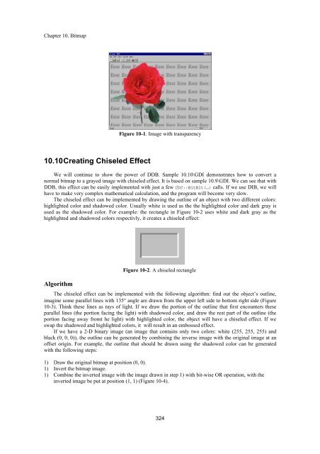
- Page 323 and 324: Chapter 10. Bitmap used as the orig
- Page 325 and 326: Chapter 10. Bitmap With the above i
- Page 327 and 328: Chapter 10. Bitmap …… …… if
- Page 329 and 330: Chapter 10. Bitmap …… } } { if(
- Page 331 and 332: Chapter 10. Bitmap …… } rgbQuad
- Page 333 and 334: Chapter 10. Bitmap DIB Section Both
- Page 335 and 336: Chapter 10. Bitmap } } if(m_pBmpMas
- Page 337 and 338: Chapter 10. Bitmap …… m_pBmpOld
- Page 339: Chapter 10. Bitmap BITMAP bm; …
- Page 343 and 344: Chapter 10. Bitmap 1) Paint the des
- Page 345 and 346: Chapter 10. Bitmap color bitmap, bu
- Page 347 and 348: Chapter 10. Bitmap will destroy the
- Page 349 and 350: Chapter 10. Bitmap 10) The total im
- Page 351 and 352: Chapter 11. Sample: Simple Paint Af
- Page 353 and 354: Chapter 11. Sample: Simple Paint CG
- Page 355 and 356: Chapter 11. Sample: Simple Paint Th
- Page 357 and 358: Chapter 11. Sample: Simple Paint Co
- Page 359 and 360: Chapter 11. Sample: Simple Paint vo
- Page 361 and 362: Chapter 11. Sample: Simple Paint m_
- Page 363 and 364: Chapter 11. Sample: Simple Paint cu
- Page 365 and 366: Chapter 11. Sample: Simple Paint Te
- Page 367 and 368: Chapter 11. Sample: Simple Paint
- Page 369 and 370: Chapter 11. Sample: Simple Paint CS
- Page 371 and 372: Chapter 11. Sample: Simple Paint fu
- Page 373 and 374: Chapter 11. Sample: Simple Paint
- Page 375 and 376: Chapter 11. Sample: Simple Paint DW
- Page 377 and 378: Chapter 11. Sample: Simple Paint m_
- Page 379 and 380: Chapter 11. Sample: Simple Paint co
- Page 381 and 382: Chapter 11. Sample: Simple Paint
- Page 383 and 384: Chapter 11. Sample: Simple Paint Ho
- Page 385 and 386: Chapter 11. Sample: Simple Paint 1)
- Page 387 and 388: Chapter 12. Screen Capturing & Prin
- Page 389 and 390: Chapter 12. Screen Capturing & Prin
- Page 391 and 392:
Chapter 12. Screen Capturing & Prin
- Page 393 and 394:
Chapter 12. Screen Capturing & Prin
- Page 395 and 396:
Chapter 12. Screen Capturing & Prin
- Page 397 and 398:
Chapter 12. Screen Capturing & Prin
- Page 399 and 400:
Chapter 12. Screen Capturing & Prin
- Page 401 and 402:
Chapter 12. Screen Capturing & Prin
- Page 403 and 404:
Chapter 12. Screen Capturing & Prin
- Page 405 and 406:
Chapter 12. Screen Capturing & Prin
- Page 407 and 408:
Chapter 13. Adding Special Features
- Page 409 and 410:
Chapter 13. Adding Special Features
- Page 411 and 412:
Chapter 13. Adding Special Features
- Page 413 and 414:
Chapter 13. Adding Special Features
- Page 415 and 416:
Chapter 13. Adding Special Features
- Page 417 and 418:
Chapter 13. Adding Special Features
- Page 419 and 420:
Chapter 13. Adding Special Features
- Page 421 and 422:
Chapter 13. Adding Special Features
- Page 423 and 424:
Chapter 13. Adding Special Features
- Page 425 and 426:
Chapter 13. Adding Special Features
- Page 427 and 428:
Chapter 13. Adding Special Features
- Page 429 and 430:
Chapter 13. Adding Special Features
- Page 431 and 432:
Chapter 13. Adding Special Features
- Page 433 and 434:
Chapter 13. Adding Special Features
- Page 435 and 436:
Chapter 13. Adding Special Features
- Page 437 and 438:
Chapter 13. Adding Special Features
- Page 439 and 440:
Chapter 13. Adding Special Features
- Page 441 and 442:
Chapter 13. Adding Special Features
- Page 443 and 444:
Chapter 13. Adding Special Features
- Page 445 and 446:
Chapter 14. Views ID_EDIT_PASTE pas
- Page 447 and 448:
Chapter 14. Views Another feature o
- Page 449 and 450:
Chapter 14. Views szFind=newName; s
- Page 451 and 452:
Chapter 14. Views ON_COMMAND(ID_BUT
- Page 453 and 454:
Chapter 14. Views IDB_BITMAP_CLOSEF
- Page 455 and 456:
Chapter 14. Views Because we do not
- Page 457 and 458:
Chapter 14. Views For the root dire
- Page 459 and 460:
Chapter 14. Views The columns are a
- Page 461 and 462:
Chapter 14. Views } ff.Close(); Des
- Page 463 and 464:
Chapter 14. Views …… …… if(
- Page 465 and 466:
Chapter 14. Views void CDirView::Ad
- Page 467 and 468:
Chapter 14. Views Actually, in the
- Page 469 and 470:
Chapter 14. Views } if(szName1.GetL
- Page 471 and 472:
Chapter 14. Views Mouse Cursor Coor
- Page 473 and 474:
Chapter 16. Context Sensitive Help
- Page 475 and 476:
Chapter 16. Context Sensitive Help
- Page 477 and 478:
Chapter 16. Context Sensitive Help
- Page 479 and 480:
Chapter 16. Context Sensitive Help
- Page 481 and 482:
Chapter 16. Context Sensitive Help
- Page 483 and 484:
Chapter 16. Context Sensitive Help
- Page 485 and 486:
Chapter 16. Context Sensitive Help
- Page 487 and 488:
Chapter 16. Context Sensitive Help
- Page 489 and 490:
Chapter 16. Context Sensitive Help
- Page 491 and 492:
Chapter 16. Context Sensitive Help
- Page 493 and 494:
Chapter 16. Context Sensitive Help
- Page 495 and 496:
Chapter 16. Context Sensitive Help
- Page 497 and 498:
Chapter 16. Context Sensitive Help
- Page 499 and 500:
Chapter 16. Context Sensitive Help
- Page 501 and 502:
Chapter 16. Context Sensitive Help
- Page 503 and 504:
Chapter 16. Context Sensitive Help
- Page 505 and 506:
Chapter 16. Context Sensitive Help
- Page 507 and 508:
Appendix A. Virtual-key Codes Appen
- Page 509 and 510:
Appendix A. Virtual-key Codes Funct
- Page 511 and 512:
Appendix B. Ternary Raster Operatio
- Page 513 and 514:
Appendix B. Ternary Raster Operatio
- Page 515 and 516:
Appendix B. Ternary Raster Operatio
- Page 517 and 518:
Index Index #if, 416 #pragma, 416 .
- Page 519 and 520:
Index CDC::SetPixel, 321 CDC::SetRO
- Page 521 and 522:
Index CRectTracker, 345 CRectTracke
- Page 523 and 524:
Index CWnd::SetMenu, 55 CWnd::SetTi
- Page 525 and 526:
Index HBRUSH, 201 HCURSOR, 262 HDAT
- Page 527 and 528:
Index Background palette, 224 Chang
- Page 529 and 530:
Index Default tool bar, 1 Enable or