Create successful ePaper yourself
Turn your PDF publications into a flip-book with our unique Google optimized e-Paper software.
Ford Motor Company<br />
Transportation & Mobility <strong>Case</strong> <strong>Study</strong>
Challenge<br />
Develop a robust cantilevered conical joint design, while<br />
minimizing cost and time in order to meet functional targets.<br />
Solution<br />
Using Abaqus for CATIA (AFC) for structural analysis and Isight<br />
for process automation and optimization, the engineering team<br />
at Ford is able to develop an automated Design of Experiments<br />
process to eliminate design inefficiencies and allow them to<br />
complete their analysis in four days rather than an estimated<br />
70 days.<br />
Benefits<br />
Utilizing AFC and Isight, the Ford engineering team was able to<br />
achieve their project goals in a fraction of the time it would<br />
have otherwise taken. Their initial time investment in<br />
completely automating the testing process will save them<br />
countless weeks of development time in the future.<br />
Developing high-quality bolted joints is an integral part of vehicle<br />
chassis design. While less understood than the design of connecting<br />
members, such as a toe-link that connects the sub frame to the<br />
knuckle, robust joints are critical to improving handling and<br />
longevity of vehicle performance. Joints that are loose tend to<br />
exacerbate quality issues such as alignment, and ultimately the<br />
durability of the joined components. A properly designed joint is<br />
more efficient and can support larger loads with smaller size<br />
fasteners without loosening.<br />
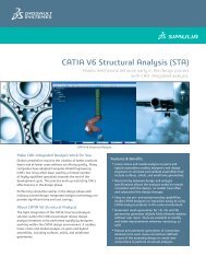
Engineers at Ford Motor Company were tasked to deliver a robust<br />
cantilevered conical joint design for the rear suspension system of a<br />
midsize passenger car (see Figure 1). To minimize time and cost while<br />
meeting functional targets, the team developed an automated Design<br />
of Experiments (DOE) process using Abaqus for CATIA (AFC) for<br />
structural analysis and Isight for process automation and<br />
optimization.<br />
“Our team chose AFC in order to deploy standard stress modeling and<br />
simulation practices in the form of templates to a broader group of<br />
engineers within the design organization,” says Satyendra Savanur,<br />
chassis CAE engineer at Ford. ”Linking Isight with AFC enabled us to<br />
develop a powerful and automated design analysis methodology. We<br />
used response surface model, one of the approximation models, for<br />
finding optimal parameters to size the joint.”<br />
Analyzing conical joint performance<br />
A bolted joint is the most common type of attachment method used<br />
in the suspension of a car. In this application, a conical joint is used<br />
Figure 1. Close-up view, before assembly, of the toe-link (black) and the rear knuckle (silver)<br />
using a conical joint.<br />
for connecting the toe-link to the rear knuckle with a cantilevered<br />
type connection. The two mating parts of the conical joint—the<br />
bushing inner sleeve and the knuckle—each have unique<br />
manufacturing tolerances of the cone angle.<br />
To develop a robust conical joint between a steel inner sleeve and an<br />
aluminum knuckle the following aspects were considered:<br />
manufacturing tolerances of each component, contact area between<br />
the cone and seat, angle of the cone torque loss after the service load<br />
is removed.<br />
To perform virtual tests of their design, the Ford engineers used AFC<br />
to create the finite element model of the knuckle and the bushing<br />
inner sleeve with the geometry input and material properties from<br />
their model created in CATIA. AFC maintains associativity with the<br />
CATIA model to ensure that the Abaqus model updates are robust<br />
when the CAD model is changed within the usable range of design<br />
variables.<br />
“It is estimated it would have taken<br />
approximately 70 days to complete<br />
all 35 runs, while maintaining other<br />
day-to-day work; we completed this<br />
task in about four days.”<br />
Satyendra Savanur, Chassis CAE Engineer,<br />
Ford Motor Company<br />
Transportation & Mobility <strong>Case</strong> <strong>Study</strong>: Ford 2<br />
© 2013 Dassault Systèmes
During the physical assembly process, a forged steel inner cone is<br />
forced against an aluminum knuckle seat. Due to the different<br />
manufacturing processes used to make each part, the angular<br />
tolerances of the conical design features are different on the inner<br />
sleeve and the knuckle mating surface.<br />
“Because of the potential angular mismatch, there are variations in<br />
contact area when the two surfaces mate together and the joint is<br />
fully torqued,” says Savanur. Local yielding can occur in the mating<br />
materials, leading to changes in contact area and pressure<br />
distribution during assembly of the joint. When the service load is<br />
applied, further changes to the contact area and contact pressure can<br />
occur.<br />
“It is, therefore, important to simulate both the joint assembly and<br />
the loading and unloading of service loads on the joint during the<br />
analysis,” he says. “Our objective was to deliver a robust conical joint<br />
design for the entire range of conical mismatch between the cone<br />
and the knuckle.”<br />
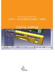
For a robust contact analysis and even contact pressure distribution,<br />
the mesh of the inner sleeve was constructed to align with the mesh<br />
of the knuckle seat. To facilitate mesh alignment in the contact area,<br />
a separate “domain” of the knuckle seat (shown in turquoise in<br />
Figure 2) was created to simplify meshing. This part was connected<br />
to the rest of the knuckle body with a tied contact in Abaqus.<br />
To simulate the bolt assembly process, a virtual bolt between the<br />
inner sleeve and the knuckle joint seat was created. External service<br />
loads were applied on the sleeve center. Nonlinear stress-strain<br />
curves for aluminum and steel were imported into AFC to facilitate<br />
the nonlinear analysis. Contact pairs and bolt tension were all<br />
created inside AFC. Output of contact area (CAREA) and contact force<br />
magnitude (CFNM) were possible using AFC for postprocessing.<br />
Finally, the Abaqus analysis file was output and submitted to the<br />
high-performance computing (HPC) cluster for running the analyses.<br />
Managing the DOE process<br />
Ford’s need to evaluate a large number of designs with different<br />
combinations of parameters prompted the engineers to create an<br />
automated DOE process. In this process, CAD geometry updates and<br />
FEA model updates are completed in the same loop thus allowing a<br />
completely automated DOE approach.<br />
At Ford, CATIA startup is customized with an external product<br />
management system. Scripting is used to strip away the linkages to<br />
the product management system before initializing the CATIA<br />
interface.<br />
Design parameters are then fed into CATIA with an external Excel file,<br />
a common method used to update a design table within CATIA. The<br />
input parameters from the Excel file are mapped to the DOE task of<br />
the Isight manager. This enabled automatic updates of the Excel<br />
Figure 2. CAE mesh details of the conical joint.<br />
sheet for each loop. Since Excel is synchronized with the design<br />
table, this results in automatic updates of the CAD geometry inside<br />
CATIA. Within AFC, geometry and FE mesh are associated, so the<br />
resulting mesh is updated to the changed CAD data.<br />
“By developing a single integrated process, we were able to drive<br />
automatic updates of the geometry and mesh at the same time,” says<br />
Savanur. To manage and control the DOE process, Isight was used as<br />
the process automation manager. The resulting automation loop is<br />
completely integrated to run CATIA and AFC for CAD updates, create<br />
the Abaqus FE models, and submit job submission for analysis and<br />
post-process results.<br />
The Abaqus component inside the Isight loop was used to extract<br />
outputs, including CAREA and CFNM for each run of the DOE (see<br />
Figure 3). The input parameters from the Excel file are then mapped<br />
to these output parameters to create an Isight approximation model.<br />
“In our case, we used the response surface model method of<br />
approximation,” says Savanur. This approximate model of conical<br />
joint behavior can then be used to show how input affects output<br />
and quickly optimize the conical joint.<br />
“This is the first application of an integrated DOE automation loop to<br />
morph geometry using CATIA with Abaqus at Ford,” says Savanur.<br />
Isight enables more efficient processes<br />
The set-up and validation of the CATIA and AFC scripts, HPC job<br />
submission batch file, and the Windows batch command file took<br />
time and resources to develop, but were well worth it as they are<br />
reusable for subsequent projects with minor changes.<br />
“Developing a comparable CATIA model with an associated Excel<br />
design table, and linked to an associated AFC model would take<br />
© 2013 Dassault Systèmes 3<br />
Transportation & Mobility <strong>Case</strong> <strong>Study</strong>: Ford
DOE1<br />
Excel Pause for XLS CATIA Run NIC Job Pause for STA Refresh Copy INP Abaqus OS Command Calculator<br />
update<br />
Figure 3. Integrated DOE automation loop using Isight.<br />
approximately three days to construct,” says Savanur. “Modifying<br />
and debugging the previously developed scripts to run with these<br />
new models would take another day. Using Isight, it took about 3.5<br />
hours for the process to complete 35 analysis runs.”<br />
“Typically, the manual CAE process consumes two days just to<br />
complete one run. Of course, this timing can be reduced if the project<br />
is critical, but this is the typical day-to-day turnaround time<br />
balancing several projects per engineer,” says Joe Peters, chassis CAE<br />
supervisor at Ford.<br />
Time inefficiencies typically occur in the transfer of data back and<br />
forth between CAE and CAD organizations, as people have multiple<br />
assignments and do not immediately stop their current work when<br />
new design iterations are requested; this is analogous to CPU time<br />
verses wall clock time.<br />
“It is estimated it would have taken approximately 70 days to<br />
complete all 35 runs, while maintaining other day-to-day work;<br />
whereas, our new process eliminates the inefficiencies that were part<br />
of the manual CAD/CAE procedures,” says Savanur. “By creating an<br />
integrated and automated closed-loop DOE process using Isight, we<br />
completed this task in about four days. This was the only way to help<br />
achieve the program objectives of cost and timing with a lean CAE<br />
organization.”<br />
“Using the automated DOE process, we were able to drastically cut<br />
down the time required to develop a robust conical joint with<br />
minimal resources,” says Peters. “The largest amount of time savings<br />
was realized in the automated process of creating a CAE model from<br />
CAD. This is a testament to the fact that a small CAE team using new<br />
innovative technology helped Ford to achieve program objectives.”<br />
By using AFC and creating an integrated closed-loop DOE process<br />
with the help of Isight, Ford was able to deliver a robust conical joint<br />
design. This joint exhibits good contact area and retains clamp load<br />
after load removal, within the specified manufacturing tolerances.<br />
Transportation & Mobility <strong>Case</strong> <strong>Study</strong>: Ford 4<br />
© 2013 Dassault Systèmes
Delivering Best-in-Class Products<br />
Virtual Product<br />
3D Design<br />
Realistic Simulation<br />
Digital Manufacturing<br />
Collaborative Innovation<br />
Dassault Systèmes, the 3DEXPERIENCE Company, provides business and people with virtual<br />
universes to imagine sustainable innovations. Its world-leading solutions transform the way<br />
products are designed, produced, and supported. Dassault Systèmes’ collaborative solutions<br />
foster social innovation, expanding possibilities for the virtual world to improve the real world.<br />
The group brings value to over 150,000 customers of all sizes, in all industries, in more than<br />
80 countries. For more information, visit www.3ds.com.<br />
Europe/Middle East/Africa<br />
Dassault Systèmes<br />
10, rue Marcel Dassault<br />
CS 40501<br />
78946 Vélizy-Villacoublay Cedex<br />
France<br />
Visit us at<br />
3DS.COM/SIMULIA<br />
Information Intelligence<br />
Virtual Planet<br />
Dashboard Intelligence<br />
Social Innovation<br />
3D Communication<br />
Asia-Pacific<br />
Dassault Systèmes<br />
Pier City Shibaura Bldg 10F<br />
3-18-1 Kaigan, Minato-Ku<br />
Tokyo 108-002<br />
Japan<br />
Americas<br />
Dassault Systèmes<br />
175 Wyman Street<br />
Waltham, Massachusetts<br />
02451-1223<br />
USA<br />
© Dassault Systèmes 2012, all rights reserved. CATIA, SOLIDWORKS, SIMULIA, DELMIA, ENOVIA, EXALEAD, NETVIBES, 3DSWYM, 3DVIA are registered trademarks of Dassault Systèmes or its subsidiaries in the US and/or other countries. Images courtesy of Strand Aerospace Malaysia.<br />
www.3ds.com/solutions/aerospace-defense/overview