Appnote - Nti
Appnote - Nti
Appnote - Nti

Create successful ePaper yourself
Turn your PDF publications into a flip-book with our unique Google optimized e-Paper software.
AppNote<br />
Test the polarity of your mics<br />
The relative polarity test of your mikes is very useful to know when<br />
recording or amplifying sound with a lot of mikes. A combination of the<br />
NTI audio generator Minirator MR 1, the audio analyzer ML1 and a doit-yourself<br />
adapter will be able to give you the answer to one of your<br />
questions. Is it the right polarity?<br />
Preparing the test<br />
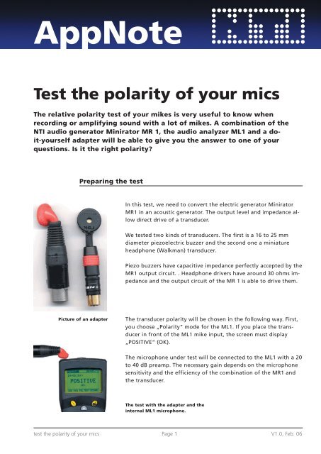
Picture of an adapter<br />
In this test, we need to convert the electric generator Minirator<br />
MR1 in an acoustic generator. The output level and impedance allow<br />
direct drive of a transducer.<br />
We tested two kinds of transducers. The first is a 16 to 25 mm<br />
diameter piezoelectric buzzer and the second one a miniature<br />
headphone (Walkman) transducer.<br />
Piezo buzzers have capacitive impedance perfectly accepted by the<br />
MR1 output circuit. . Headphone drivers have around 30 ohms impedance<br />
and the output circuit of the MR 1 is able to drive them.<br />
The transducer polarity will be chosen in the following way. First,<br />
you choose „Polarity“ mode for the ML1. If you place the transducer<br />
in front of the ML1 mike input, the screen must display<br />
„POSITIVE“ (OK).<br />
The microphone under test will be connected to the ML1 with a 20<br />
to 40 dB preamp. The necessary gain depends on the microphone<br />
sensitivity and the efficiency of the combination of the MR1 and<br />
the transducer.<br />
The test with the adapter and the<br />
internal ML1 microphone.<br />
test the polarity of your mics Page 1 V1.0, Feb. 06
Measurements<br />
Measurement principle<br />
Minirator MR1: Choose the “Pol test” signal and the maximum<br />
output level. (1,25 V or +4 dBu)<br />
Select „Unit: V“ or „Unit : dBu“ in the Setup menu of the MR1.<br />
Minilyzer ML1: Use “Polarity” function, the microphone<br />
polarity relative to the internal mike of the ML1 will be displayed<br />
directly on the Minilyzer screen: “POSITIVE” (OK) or “NEGATIVE”<br />
(REVERSE).<br />
Test of a sound system:<br />
To test the polarity of all the microphones connected to a mixing<br />
desk, the ML1 is connected to one of the outputs of the console<br />
(available on stage if necessary). The MR1 and its adapter will then<br />
be successively placed in front of all the concerned microphones.<br />
This test will show the microphone polarity, the cable problems<br />
and a wrong polarity switch position.<br />
Wireless microphones will be tested with the same procedure.<br />
The MR 1 generates an asymmetrical electrical signal allowing<br />
the detection of a signal phase. The adapter converts the electric<br />
signal in an acoustic wave going into the under test mike. The ML1<br />
analyses the signal coming from the microphone by four ways and<br />
if the result is consistent, displays its polarity.<br />
When we are in the acoustic domain, the importance of the phase<br />
becomes relative. A PA system can work without any problem in<br />
or out of phase. What is important is the relative respect of the<br />
relative phase of different microphones capturing the same sound<br />
source. With opposite phase, we can have many cancellations.<br />
In this application, we can also test the absolute phase if you consider<br />
that the ML1 gives the absolute reference.<br />
Text and application idea of Mr. Etienne Lemery. Many thanks!<br />
Thomas Hupp / NTI AG<br />
test the polarity of your mics Page 2 V1.0, Feb. 06