Read Article - CB&I
Read Article - CB&I Read Article - CB&I
Seismic System Selection Either ASCE 7 Table 12.2-1 or ASCE 7 Table 15.4-1 can be used to choose a seismic force-resisting system, which will provide the prescribed seismic detailing requirements, design parameters (R, Ω o , C d ), and height limitations. Table 15.4-1 permits select types of nonbuilding structures that have performed well in past earthquakes to be constructed with less restrictive height limitations in Seismic Design Categories (SDC) D, E, and F than those specified in Table 12.2-1. Note that Table 15.4-1 includes options where seismic detailing per AISC 341 is not required for SDC D, E, or F. For example, steel ordinary moment frames can be designed with R = 1 without seismic detailing. Seismic detailing requirements can also be avoided in SDC B and C for any structural steel system if R = 3 or less, excluding cantilevered column systems. The transverse bents are usually momentresisting frame systems. The choices are special moment frame (SMF), intermediate moment frame (IMF), or ordinary moment frame (OMF). In the longitudinal direction, when bracing is present, the choices are usually special concentrically braced frame or ordinary concentrically braced frame. Less common choices are eccentrically braced frame or buckling-restrained braced frame. If bracing is not present, the choices in the longitudinal direction are the cantilevered column systems. In both directions, the seismic system selected must be permitted for both the SDC and the pipe rack height. ASCE 7 Table 15.4-1 footnotes permit specific height limits for pipe racks detailed with specific seismic systems: • With R = 3.25, “Steel ordinary braced frames are permitted in pipe racks up to 65 feet (20 m).” • With R = 3.5, “Steel ordinary moment frames are permitted in pipe racks up to a height of 65 feet (20 m) where the moment joints of field connections are constructed of bolted end plates. Steel ordinary moment frames are permitted in pipe racks up to a height of 35 feet (11 m).” • With R = 4.5, “Steel intermediate moment frames are permitted in pipe racks up to a height of 65 feet (20 m) where the moment joints of field connections are constructed of bolted end plates. Steel intermediate moment frames are permitted in pipe racks up to a height of 35 feet (11 m).” Period Calculations The fundamental period determined from ASCE 7 Chapter 12 equations is not applicable for nonbuilding structures, including pipe racks, because they do not have the same mass and stiffness distributions assumed for buildings. It is acceptable to use any analysis approach that accurately includes the mass and stiffness of the structure, including finite element models and the Rayleigh method. The determination of the pipe rack period can be affected by the stiffness of the piping leaving the pipe rack. When this stiffness is not accounted for in the period calculation, it is recommended that the calculated period be reduced by 10%. Analysis Procedure Selection Static or dynamic analysis methods can be used. Static procedures are allowed only under certain conditions of regularity, occupancy, and height. ASCE 7 Chapter 12 specifies when a dynamic analysis is required. The philosophy underlying this section is that dynamic analysis is always acceptable for design. A dynamic analysis procedure is required for a pipe rack if it is assigned to SDC D, E, or F and it either: • has T ≥ 3.5T s ; • exhibits horizontal irregularity type 1a or 1b; or • exhibits vertical irregularity type 1a, 1b, 2, or 3. The most common dynamic procedure used for pipe racks is modal response spectrum analysis. The equivalent lateral force (ELF) procedure is allowed for a pipe rack structure if a dynamic analysis procedure is not required. The simplified alternative structural design criteria for Figure 2: Typical 4-level pipe rack consisting of nine transverse frames connected by longitudinal struts. simple bearing wall or building frame systems are not appropriate and should not be used for pipe racks. Equivalent Lateral Force Procedure The ELF procedure involves calculating the effective earthquake loads in terms of a static base shear that is dependent on the imposed ground acceleration and the structure’s mass (effective seismic weight), dynamic characteristics, ductility and importance. The base shear is then applied to the structure as an equivalent lateral load vertically distributed to the various elevations using code-prescribed equations that are applicable to building structures. Using this vertical distribution of forces, seismic design loads in individual members and connections can be determined. ASCE 7 determines design earthquake forces on a strength basis, allowing direct comparison with the design strength of individual structural members. continued on next page The easiest to use software for calculating wind, seismic, snow and other loadings for IBC, ASCE7, and all state codes based on these codes ($195.00). Tilt-up Concrete Wall Panels ($95.00). Floor Vibration for Steel Beams and Joists ($100.00). Concrete beams with torsion ($45.00). Demos at: www.struware.com ADVERTISEMENT - For Advertiser Information, visit www.STRUCTUREmag.org STRUCTURE magazine 15 February 2012
Figure 3: AISC 358 extended end plate connections. Modal Response Spectrum Analysis MRSA is acceptable for the analysis of pipe racks, and may be required if certain plan and/ or vertical irregularities are identified. The basis of MRSA is that the pipe rack’s mass (effective seismic weight) and stiffness are carefully modeled, allowing the dynamic analysis of multiple vibration modes that result in an accurate distribution of the base shear forces throughout the structure. The MRSA must include a sufficient number of modes in order to achieve a minimum of 90% mass participation. Two MRSA runs are typically required for pipe racks. The first run includes the operating dead load (D o ) as the seismic effective weight to determine the operating earthquake load (E o ). The second run includes the empty dead load (D e ) as the seismic effective weight to determine the empty earthquake load (E e ). The MRSA input ground motion parameters (S DS , S D1 ) are used to define the ASCE 7 elastic design response spectrum. To obtain “static force levels,” the MRSA force results must be divided by the quantity (R/I). ASCE 7 does not allow an engineer to scale down MRSA force levels to ELF force levels because the ELF procedure may result in an underprediction of response for structures with significant higher-mode participation. On the other hand, when the MRSA base shear is less than 85% of the ELF base shear, the MRSA results must be scaled up to no less than 85% of the ELF values. This lower limit on the design base shear is imposed to account for higher mode effects, and to ensure that the design forces are not underestimated through the use of a structural model that does not accurately represent the mass and stiffness characteristics of the pipe rack. Drift To obtain amplified seismic displacements, the displacement results calculated from the elastic analysis must be multiplied by the quantity (C d /I e ) to account for the expected inelastic deformations when checking against the drift limits of ASCE 7 Table 12.12-1. The displacement results must be multiplied by C d for checking pipe flexibility and structure separation. It is important that the drift of pipe racks be compared to other adjacent structures where piping and cable trays run. The piping and cable trays must be flexible enough to accommodate the movements of the pipe rack relative to these structures. Seismic Detailing Requirements The selection of a seismic force-resisting system from ASCE 7 Table 12.2-1 dictates detailing requirements prescribed in ASCE 7 Chapter 14. Because this chapter is specifically excluded by the IBC, seismic detailing requirements for structural steel systems must be taken instead from IBC Chapter 22 and AISC 341. The selection of a seismic forceresisting system from ASCE 7 Table 15.4-1 directly dictates seismic detailing requirements prescribed in AISC 341. AISC 341 includes such requirements for each structural steel system listed in the two ASCE 7 tables. In general, there is a relationship between R values and seismic detailing requirements. Lower R values and higher earthquake design forces are accompanied by minimal seismic detailing requirements. Higher R values and lower earthquake design forces are accompanied by more restrictive seismic detailing requirements to provide greater ductility. AISC 341 prescribes that beams in OMF systems do not require lateral bracing beyond those requirements prescribed in AISC 360. However, beams in IMF and SMF systems have progressively more restrictive requirements for lateral bracing of beams that can only be met by the addition of a horizontal bracing system at each pipe level. For this reason, it may be more economical to select an OMF system for the transverse bents. AISC 341 prescribes that beam-tocolumn connections for IMF and SMF systems be based on laboratory testing. OMF beam-to-column connections may be either calculated to match the expected plastic moment strength of the beam or based on laboratory testing. AISC 358 prescribes specific requirements for laboratory-tested systems appropriate for use in seismic moment frames. One of the systems included in AISC 358 is the bolted endplate moment connection, commonly used in pipe rack construction (Figure 3). These connections are popular in industrial plants because they involve no field welding. Redundancy in SDC A, B, or C In accordance with ASCE 7, for all structures, ρ = 1.0. Redundancy in SDC D, E, or F The typical pipe rack has no horizontal bracing system that serves as a diaphragm. If one individual bent fails, there is no load path for lateral force transfer to the adjacent frame. As a result, the pipe rack must be treated as a non-redundant structure. • For a transverse bent to qualify for ρ = 1.0, it must have four or more columns and three or more bays at each level. This ensures that the loss of moment resistance at both ends of a single beam does not result in more than a 33% loss of story strength. Otherwise, ρ = 1.3. • For an individual longitudinal braced frame to qualify for ρ = 1.0, it must have two or more bays of chevron or X bracing (or four individual braces) at each level on each frame line. This ensures that the loss of an individual brace or connection does not result in more than a 33% loss of story strength nor cause an extreme torsional irregularity (Type 1b). Otherwise, ρ = 1.3. If the pipe rack is provided with a horizontal bracing system that serves as a diaphragm and provides a load path for lateral transfer, it can be treated as a redundant structure. • For a pipe rack to qualify in the transverse direction for ρ = 1.0, it needs to have horizontal bracing between all transverse bents and a minimum of four transverse bents. Otherwise, ρ = 1.3. • For a pipe rack to qualify in the longitudinal direction for ρ = 1.0, there needs to be a minimum of four transverse bents, and each longitudinal frame line needs to have two or more individual braces at each level. Otherwise, ρ = 1.3.▪ STRUCTURE magazine 16 February 2012
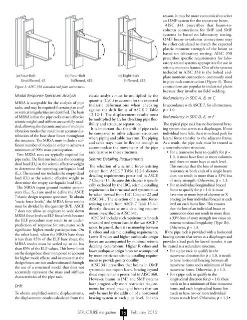
Figure 3: AISC 358 extended end plate connections.<br />
Modal Response Spectrum Analysis<br />
MRSA is acceptable for the analysis of pipe<br />
racks, and may be required if certain plan and/<br />
or vertical irregularities are identified. The basis<br />
of MRSA is that the pipe rack’s mass (effective<br />
seismic weight) and stiffness are carefully modeled,<br />
allowing the dynamic analysis of multiple<br />
vibration modes that result in an accurate distribution<br />
of the base shear forces throughout<br />
the structure. The MRSA must include a sufficient<br />
number of modes in order to achieve a<br />
minimum of 90% mass participation.<br />
Two MRSA runs are typically required for<br />
pipe racks. The first run includes the operating<br />
dead load (D o ) as the seismic effective weight<br />
to determine the operating earthquake load<br />
(E o ). The second run includes the empty dead<br />
load (D e ) as the seismic effective weight to<br />
determine the empty earthquake load (E e ).<br />
The MRSA input ground motion parameters<br />
(S DS , S D1 ) are used to define the ASCE<br />
7 elastic design response spectrum. To obtain<br />
“static force levels,” the MRSA force results<br />
must be divided by the quantity (R/I). ASCE<br />
7 does not allow an engineer to scale down<br />
MRSA force levels to ELF force levels because<br />
the ELF procedure may result in an underprediction<br />
of response for structures with<br />
significant higher-mode participation. On<br />
the other hand, when the MRSA base shear<br />
is less than 85% of the ELF base shear, the<br />
MRSA results must be scaled up to no less<br />
than 85% of the ELF values. This lower limit<br />
on the design base shear is imposed to account<br />
for higher mode effects, and to ensure that the<br />
design forces are not underestimated through<br />
the use of a structural model that does not<br />
accurately represent the mass and stiffness<br />
characteristics of the pipe rack.<br />
Drift<br />
To obtain amplified seismic displacements,<br />
the displacement results calculated from the<br />
elastic analysis must be multiplied by the<br />
quantity (C d /I e ) to account for the expected<br />
inelastic deformations when checking<br />
against the drift limits of ASCE 7 Table<br />
12.12-1. The displacement results must<br />
be multiplied by C d for checking pipe flexibility<br />
and structure separation.<br />
It is important that the drift of pipe racks<br />
be compared to other adjacent structures<br />
where piping and cable trays run. The piping<br />
and cable trays must be flexible enough to<br />
accommodate the movements of the pipe<br />
rack relative to these structures.<br />
Seismic Detailing Requirements<br />
The selection of a seismic force-resisting<br />
system from ASCE 7 Table 12.2-1 dictates<br />
detailing requirements prescribed in ASCE<br />
7 Chapter 14. Because this chapter is specifically<br />
excluded by the IBC, seismic detailing<br />
requirements for structural steel systems must<br />
be taken instead from IBC Chapter 22 and<br />
AISC 341. The selection of a seismic forceresisting<br />
system from ASCE 7 Table 15.4-1<br />
directly dictates seismic detailing requirements<br />
prescribed in AISC 341.<br />
AISC 341 includes such requirements for each<br />
structural steel system listed in the two ASCE 7<br />
tables. In general, there is a relationship between<br />
R values and seismic detailing requirements.<br />
Lower R values and higher earthquake design<br />
forces are accompanied by minimal seismic<br />
detailing requirements. Higher R values and<br />
lower earthquake design forces are accompanied<br />
by more restrictive seismic detailing requirements<br />
to provide greater ductility.<br />
AISC 341 prescribes that beams in OMF<br />
systems do not require lateral bracing beyond<br />
those requirements prescribed in AISC 360.<br />
However, beams in IMF and SMF systems<br />
have progressively more restrictive requirements<br />
for lateral bracing of beams that can<br />
only be met by the addition of a horizontal<br />
bracing system at each pipe level. For this<br />
reason, it may be more economical to select<br />
an OMF system for the transverse bents.<br />
AISC 341 prescribes that beam-tocolumn<br />
connections for IMF and SMF<br />
systems be based on laboratory testing.<br />
OMF beam-to-column connections may<br />
be either calculated to match the expected<br />
plastic moment strength of the beam or<br />
based on laboratory testing. AISC 358<br />
prescribes specific requirements for laboratory-tested<br />
systems appropriate for use in<br />
seismic moment frames. One of the systems<br />
included in AISC 358 is the bolted endplate<br />
moment connection, commonly used<br />
in pipe rack construction (Figure 3). These<br />
connections are popular in industrial plants<br />
because they involve no field welding.<br />
Redundancy in SDC A, B, or C<br />
In accordance with ASCE 7, for all structures,<br />
ρ = 1.0.<br />
Redundancy in SDC D, E, or F<br />
The typical pipe rack has no horizontal bracing<br />
system that serves as a diaphragm. If one<br />
individual bent fails, there is no load path for<br />
lateral force transfer to the adjacent frame.<br />
As a result, the pipe rack must be treated as<br />
a non-redundant structure.<br />
• For a transverse bent to qualify for ρ =<br />
1.0, it must have four or more columns<br />
and three or more bays at each level.<br />
This ensures that the loss of moment<br />
resistance at both ends of a single beam<br />
does not result in more than a 33% loss<br />
of story strength. Otherwise, ρ = 1.3.<br />
• For an individual longitudinal braced<br />
frame to qualify for ρ = 1.0, it must<br />
have two or more bays of chevron or X<br />
bracing (or four individual braces) at each<br />
level on each frame line. This ensures<br />
that the loss of an individual brace or<br />
connection does not result in more than<br />
a 33% loss of story strength nor cause an<br />
extreme torsional irregularity (Type 1b).<br />
Otherwise, ρ = 1.3.<br />
If the pipe rack is provided with a horizontal<br />
bracing system that serves as a diaphragm and<br />
provides a load path for lateral transfer, it can<br />
be treated as a redundant structure.<br />
• For a pipe rack to qualify in the<br />
transverse direction for ρ = 1.0, it needs<br />
to have horizontal bracing between all<br />
transverse bents and a minimum of four<br />
transverse bents. Otherwise, ρ = 1.3.<br />
• For a pipe rack to qualify in the<br />
longitudinal direction for ρ = 1.0, there<br />
needs to be a minimum of four transverse<br />
bents, and each longitudinal frame line<br />
needs to have two or more individual<br />
braces at each level. Otherwise, ρ = 1.3.▪<br />
STRUCTURE magazine 16 February 2012


