1 Programming PIC Microcontrollers in PicBasic Pro – Servos ...
1 Programming PIC Microcontrollers in PicBasic Pro – Servos ...
1 Programming PIC Microcontrollers in PicBasic Pro – Servos ...

You also want an ePaper? Increase the reach of your titles
YUMPU automatically turns print PDFs into web optimized ePapers that Google loves.
<strong><strong>Pro</strong>gramm<strong>in</strong>g</strong> <strong>PIC</strong> <strong>Microcontrollers</strong> <strong>in</strong> <strong>PicBasic</strong> <strong>Pro</strong> <strong>–</strong> <strong>Servos</strong><br />
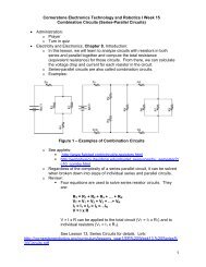
Cornerstone Electronics Technology and Robotics II<br />
4 Hour Class<br />
<br />
<br />
<br />
Adm<strong>in</strong>istration:<br />
o Prayer<br />
o Turn <strong>in</strong> Quiz 4<br />
<strong>PicBasic</strong> <strong>Pro</strong> <strong>Pro</strong>grams Used <strong>in</strong> This Lesson:<br />
o General <strong>PicBasic</strong> <strong>Pro</strong> <strong>Pro</strong>gram List<strong>in</strong>g:<br />
http://www.cornerstonerobotics.org/picbasic.php<br />
o Lab 1 switch1 as .pdf:<br />
http://www.cornerstonerobotics.org/code/switch1.pdf<br />
o Lab 2 master_slave_master1 as pdf:<br />
http://www.cornerstonerobotics.org/code/master_slave_master1.pdf<br />
o Lab 2 master_slave_slave1 as pdf:<br />
http://www.cornerstonerobotics.org/code/master_slave_slave1.pdf<br />
o Lab 3 servo1 as .pdf file:<br />
http://www.cornerstonerobotics.org/code/servo1.pdf<br />
o Lab 3 servo2 as .pdf file:<br />
http://www.cornerstonerobotics.org/code/servo2.pdf<br />
o Lab 3 servo3 as .pdf file:<br />
http://www.cornerstonerobotics.org/code/servo3.pdf<br />
o Lab3 servo4 as .pdf file:<br />
http://www.cornerstonerobotics.org/code/servo4.pdf<br />
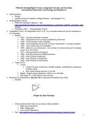
<strong><strong>Pro</strong>gramm<strong>in</strong>g</strong> <strong>PIC</strong> <strong>Microcontrollers</strong>, <strong>PicBasic</strong> <strong>Pro</strong> Basics:<br />
o Comments cont<strong>in</strong>ued:<br />
• Use lots of comments. Even though it may be perfectly obvious<br />
to you what the code is do<strong>in</strong>g as you write it, someone else<br />
look<strong>in</strong>g at the program may not have any idea of what you were<br />
try<strong>in</strong>g to achieve. While comments take up space (memory) <strong>in</strong><br />
your Basic source file, they do not take up any additional space<br />
<strong>in</strong> the <strong>PIC</strong>micro MCU, so use them freely.<br />
• Make the comments tell you someth<strong>in</strong>g useful about what the<br />
program is do<strong>in</strong>g. For example, “Turn on the red battery low<br />
LED” might be more useful than “Set p<strong>in</strong> 0 to 1”.<br />
• A block of comments at the beg<strong>in</strong>n<strong>in</strong>g of the program and<br />
before each section of code can describe what is about to<br />
happen <strong>in</strong> more detail than just the space rema<strong>in</strong><strong>in</strong>g after each<br />
statement. But don’t <strong>in</strong>clude a comment block <strong>in</strong>stead of<br />
<strong>in</strong>dividual l<strong>in</strong>e comments <strong>–</strong> use both.<br />
• Specify<strong>in</strong>g what each p<strong>in</strong> is connected to can be helpful <strong>in</strong><br />
remember<strong>in</strong>g what hardware this particular program is designed<br />
to run on.<br />
o Constants:<br />
• Named constants may be created <strong>in</strong> a similar manner to<br />
variables. It can be more convenient to use a constant name<br />
<strong>in</strong>stead of a constant number. The standard format for<br />
declar<strong>in</strong>g a constant is:<br />
Name of constant con Constant value<br />
1
• An example is:<br />
x con 3<br />
o P<strong>in</strong>, Variable, and Label Names:<br />
• Give p<strong>in</strong>s names that will help you or someone else decipher<br />
the program; judges <strong>in</strong> competitions are more able to follow the<br />
program logic if the p<strong>in</strong>s and variables are coherent. For<br />
example, if the right motor is connected to PORTB.1, use the<br />
VAR keyword to assign a proper name:<br />
right_motor VAR PORTB.1<br />
• Also, give variables logical names. For example, if you are<br />
count<strong>in</strong>g the number of times a switch1 is pressed, assign a<br />
variable name such as the one below:<br />
count_switch1 VAR Byte<br />
• F<strong>in</strong>ally, assign coherent names to the program labels. If the<br />
section of code is to turn the robotic car to the left, assign the<br />
label name of “left_turn”.<br />
• Identifiers (variable names and labels) may be up to 31<br />
characters long, but must not start with a digit.<br />
o Ports cont<strong>in</strong>ued:<br />
• As we set p<strong>in</strong>s <strong>in</strong> PORTB for <strong>in</strong>put or output (e.g. TRISB =<br />
%11111110), we can also set p<strong>in</strong>s to high or low us<strong>in</strong>g PORT.<br />
For example:<br />
PORTB = %00000000 sets all PORTB p<strong>in</strong>s to low (0 volts).<br />
PORTB = %11111111 sets all PORTB p<strong>in</strong>s to high (+5 volts).<br />
<br />
• Perform <strong>PIC</strong> <strong>Microcontrollers</strong> <strong><strong>Pro</strong>gramm<strong>in</strong>g</strong> 3 Lab 1 <strong>–</strong> Bl<strong>in</strong>k 3<br />
Ways.<br />
New <strong>PicBasic</strong> <strong>Pro</strong> Commands:<br />
o See the <strong>PicBasic</strong> <strong>Pro</strong> Compiler Manual by microEng<strong>in</strong>eer<strong>in</strong>g Labs, Inc.<br />
for a detailed explanation of these commands.<br />
o IF…THEN:<br />
Formats:<br />
IF Comparison(s) THEN Label<br />
IF Comparison(s) THEN Statement<br />
Explanation:<br />
The IF…THEN statement judges the comparison to whether it is<br />
true or false. If the comparison is true (any other value than 0),<br />
it will execute the THEN portion of the statement. If the<br />
comparison is false (0), it will execute the statement follow<strong>in</strong>g<br />
the IF…THEN command.<br />
2
Example:<br />
IF PORTB.0 = 1 THEN led2 'If the switch on PORTB.0 is<br />
‘pushed, PORTB.0 becomes high<br />
‘(+5V) and the comparison is true,<br />
‘so the program jumps to label<br />
‘led2<br />
Summary of Formats for IF…THEN and IF…THEN…ELSE Conditional<br />
Statements:<br />
IF Comparison(s) THEN Statement<br />
IF Comparison(s) THEN<br />
Statement<br />
Statement<br />
Statement<br />
ENDIF<br />
IF Comparison(s) THEN<br />
Statement<br />
Statement<br />
Statement<br />
ELSE<br />
Statement<br />
Statement<br />
Statement<br />
ENDIF<br />
o Perform <strong>PIC</strong> <strong>Microcontrollers</strong> <strong><strong>Pro</strong>gramm<strong>in</strong>g</strong> 3 Lab 2 <strong>–</strong> switch1.pbp<br />
o Perform <strong>PIC</strong> <strong>Microcontrollers</strong> <strong><strong>Pro</strong>gramm<strong>in</strong>g</strong> 3 Lab 3 <strong>–</strong> master_slave1<br />
3
o GOSUB:<br />
Format:<br />
GOSUB Label<br />
Explanation:<br />
Jump to the subrout<strong>in</strong>e at Label sav<strong>in</strong>g its return address on the<br />
stack. Unlike GOTO, when a RETURN statement is reached,<br />
execution resumes with the statement follow<strong>in</strong>g the last<br />
executed GOSUB statement. An unlimited number of<br />
subrout<strong>in</strong>es may be used <strong>in</strong> a program. Subrout<strong>in</strong>es may also<br />
be nested. In other words, it is possible for a subrout<strong>in</strong>e to call<br />
another subrout<strong>in</strong>e. Such subrout<strong>in</strong>e nest<strong>in</strong>g must be restricted<br />
to no more than four levels deep (12 levels for 7Cxxx and 27<br />
levels for 18Xxxx).<br />
Example:<br />
GOSUB beep<br />
‘Execute subrout<strong>in</strong>e named beep<br />
(More <strong>PicBasic</strong> <strong>Pro</strong> program code)<br />
beep:<br />
HIGH 0<br />
SOUND 1,[80,10]<br />
RETURN<br />
‘Turn on LED connected to RB0<br />
‘Sends tone to RB1<br />
‘Go back to the next l<strong>in</strong>e <strong>in</strong> the ma<strong>in</strong><br />
‘rout<strong>in</strong>e after the GOSUB command<br />
o PULSOUT:<br />
Format:<br />
PULSOUT P<strong>in</strong>, Period<br />
Explanation:<br />
Generates a pulse on P<strong>in</strong> of specified Period. The pulse is<br />
generated by toggl<strong>in</strong>g the p<strong>in</strong> twice, thus the <strong>in</strong>itial state of the<br />
p<strong>in</strong> determ<strong>in</strong>es the polarity of the pulse. If you want HIGH<br />
pulses, <strong>in</strong>itialize the p<strong>in</strong> to LOW (For example, PORTB.0 = 0).<br />
P<strong>in</strong> is automatically made an output. P<strong>in</strong> may be a constant, 0 -<br />
15, or a variable that conta<strong>in</strong>s a number 0 - 15 (e.g. B0) or a p<strong>in</strong><br />
name (e.g. PORTA.0). The resolution of PULSOUT is<br />
dependent upon the oscillator frequency. If a 4MHz oscillator is<br />
used, the Period of the generated pulse will be <strong>in</strong> 10us<br />
<strong>in</strong>crements. If a 20MHz oscillator is used, Period will have a 2us<br />
resolution. Def<strong>in</strong><strong>in</strong>g an OSC value has no effect on PULSOUT.<br />
The resolution always changes with the actual oscillator speed.<br />
4
Examples:<br />
PULSOUT PORTB.5,100 ‘ Send a pulse 1 msec long (at 4MHz) to RB5<br />
PULSOUT 2,200<br />
'Send a pulse 2 msec long to RB2.<br />
<br />
<br />
<br />
Power Supplies for Digital Circuits:<br />
o Digital circuits require power supplies that provide a stable source of<br />
power to all circuit components.<br />
o Even though our circuits are powered from a voltage regulator, motors<br />
and servos can disrupt the proper operation of the <strong>PIC</strong> microcontroller.<br />
o Make certa<strong>in</strong> that the servo power supply is separate from the <strong>PIC</strong><br />
power supply, i.e., have two +5V regulated power supplies.<br />
Otherwise, if the servo spikes the s<strong>in</strong>gle power l<strong>in</strong>e supply<strong>in</strong>g power to<br />
both the servo and the <strong>PIC</strong>, the 16F88 may reset.<br />
Introduction to <strong>Servos</strong>:<br />
o A servo is a special motor used to provide control for a desired<br />
rotational position through the use of feedback.<br />
o Most servos have a position range of 180 degrees.<br />
o A hobby servo is typically used to provide actuation for various<br />
mechanical systems such as the steer<strong>in</strong>g of a RC car, the flaps on a<br />
RC plane, or the rudder of a RC boat.<br />
Servo Connections:<br />
Black = Ground<br />
Red = +5 to +6 dc volts<br />
White/Orange = Control wire (Futaba uses a white wire)<br />
5
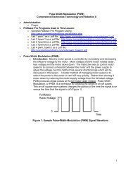
Servo Pulse Signal Widths and Period:<br />
o Pulse width for counterclockwise position:<br />
1.0 ms Pulse Width and Correspond<strong>in</strong>g Servo Position<br />
o Pulse width for center position:<br />
1.5 ms Pulse Width and Correspond<strong>in</strong>g Servo Position<br />
o Pulse width for clockwise position:<br />
2.0 ms Pulse Width and Correspond<strong>in</strong>g Servo Position<br />
o Perform LAB 4 <strong>–</strong> servo1, servo2, servo3, and servo4.<br />
6
Cornerstone Electronics Technology and Robotics II<br />
<strong><strong>Pro</strong>gramm<strong>in</strong>g</strong> <strong>PIC</strong> <strong>Microcontrollers</strong> <strong>in</strong> <strong>PicBasic</strong> <strong>Pro</strong> <strong>–</strong> <strong>Servos</strong><br />
LAB 1 <strong>–</strong> Bl<strong>in</strong>k <strong>–</strong> 3 Ways<br />
<br />
<br />
Purpose: The purpose of this lab is to re<strong>in</strong>force the three different ways to<br />
bl<strong>in</strong>k an LED.<br />
Apparatus and Materials:<br />
• 1 <strong>–</strong> Breadboard or Analog/Digital Tra<strong>in</strong>er<br />
• 1 <strong>–</strong> <strong>PIC</strong>16F88<br />
• 1 <strong>–</strong> 4.7K Resistor<br />
• 1 <strong>–</strong> 150 Ohm Resistor<br />
• 1 <strong>–</strong> LED<br />
<br />
<strong>Pro</strong>cedure:<br />
o Wire the circuit bl<strong>in</strong>k1 below on a breadboard.<br />
o Turn on and off the LED us<strong>in</strong>g the follow<strong>in</strong>g three sets of commands:<br />
PORTB.0 = 1 & PORTB.0 = 0<br />
HIGH 0 & LOW 0<br />
PORTB = %00000001 & PORTB = %00000000<br />
<br />
Challenge:<br />
o Wire an LED and a current limit<strong>in</strong>g resistor to each p<strong>in</strong> <strong>in</strong> PORTB.<br />
o <strong>Pro</strong>gram the <strong>PIC</strong>16F88 to display b<strong>in</strong>ary count<strong>in</strong>g from 0 to 255 us<strong>in</strong>g a<br />
FOR…NEXT loop and a variable “x” set up <strong>in</strong> the follow<strong>in</strong>g manner:<br />
PORTB = x<br />
PORTB = %00000000 may be written as PORTB = 0 s<strong>in</strong>ce %00000000 <strong>in</strong><br />
b<strong>in</strong>ary is equal to 0 <strong>in</strong> decimal.<br />
PORTB = %11111111 may be written as PORTB = 255 s<strong>in</strong>ce %11111111<br />
<strong>in</strong> b<strong>in</strong>ary is equal to 255 <strong>in</strong> decimal.<br />
7
Cornerstone Electronics Technology and Robotics II<br />
<strong><strong>Pro</strong>gramm<strong>in</strong>g</strong> <strong>PIC</strong> <strong>Microcontrollers</strong> <strong>in</strong> <strong>PicBasic</strong> <strong>Pro</strong> <strong>–</strong> <strong>Servos</strong><br />
LAB 2 <strong>–</strong> switch1.pbp<br />
<br />
<br />
Purpose: The purpose of this lab is to acqua<strong>in</strong>t the student with the <strong>PicBasic</strong><br />
<strong>Pro</strong> command IF…THEN and their first <strong>in</strong>put device <strong>in</strong>to a <strong>PIC</strong> MCU.<br />
Apparatus and Materials:<br />
• 1 <strong>–</strong> Breadboard or Analog/Digital Tra<strong>in</strong>er<br />
• 1 <strong>–</strong> <strong>PIC</strong>16F88<br />
• 1 <strong>–</strong> 1K Resistor<br />
• 1 <strong>–</strong> 10K Resistor<br />
• 2 <strong>–</strong> 150 Ohm Resistors<br />
• 2 <strong>–</strong> LEDs<br />
• 1 <strong>–</strong> NO Momentary Switch<br />
Brief Discussion of Pull-Down Resistor, R2:<br />
o Pull-down resistor (R2) is used to hold the <strong>in</strong>put to a zero (low) value<br />
when no other component is driv<strong>in</strong>g the <strong>in</strong>put, i.e., the switch is open.<br />
If noth<strong>in</strong>g is connected to p<strong>in</strong> RB0, the value of the <strong>in</strong>put is considered<br />
to be float<strong>in</strong>g. R2 will allow the p<strong>in</strong> to keep a steady state at zero until<br />
the switch is closed.<br />
<strong>Pro</strong>cedure:<br />
o Wire the circuit switch1 & switch2 below on a breadboard and<br />
program the 16F88 with switch1.pbp (NOT 16F877A_switch1.pbp).<br />
o Remember, the switch connected to RB0 is considered an <strong>in</strong>put<br />
device. Input devices will allow your robotic car to <strong>in</strong>teract with its<br />
environment. This is the first <strong>in</strong>put device discussed to date.<br />
o Demonstrate the program us<strong>in</strong>g the circuit switch1.<br />
<br />
Challenge:<br />
o Design a circuit and program such that a momentary switch connected to<br />
the <strong>PIC</strong> turns on and off a dc motor. Save the program as switch10.pbp.<br />
8
Cornerstone Electronics Technology and Robotics II<br />
<strong><strong>Pro</strong>gramm<strong>in</strong>g</strong> <strong>PIC</strong> <strong>Microcontrollers</strong> <strong>in</strong> <strong>PicBasic</strong> <strong>Pro</strong> <strong>–</strong> <strong>Servos</strong><br />
LAB 3 - master_slave1<br />
<br />
<br />
Purpose: The purpose of this lab is to acqua<strong>in</strong>t the student with connect<strong>in</strong>g<br />
two <strong>PIC</strong> microcontrollers such that first MCU controls the tim<strong>in</strong>g of the second<br />
MCU.<br />
Apparatus and Materials:<br />
• 1 <strong>–</strong> Breadboard or Analog/Digital Tra<strong>in</strong>er<br />
• 2 <strong>–</strong> <strong>PIC</strong>16F88<br />
• 2 <strong>–</strong> 1K Resistor<br />
• 2 <strong>–</strong> 150 Ohm Resistors<br />
• 2 <strong>–</strong> LEDs<br />
<br />
<strong>Pro</strong>cedure:<br />
o Open master_slave_master1.pbp and download to master MCU chip.<br />
Open master_slave_slave1.pbp and download to slave MCU chip.<br />
o Wire your breadboard for master_slave1 as shown below.<br />
<br />
Challenge:<br />
o Design a program and circuit us<strong>in</strong>g two <strong>PIC</strong> 16F88s where a switch<br />
connected to the first <strong>PIC</strong>16F88 program turns on/off a dc motor<br />
connected to the second <strong>PIC</strong>16F88. Save the master <strong>PIC</strong> program as<br />
msm10.pbp and the slave program as mss10.pbp.<br />
9
Cornerstone Electronics Technology and Robotics II<br />
<strong><strong>Pro</strong>gramm<strong>in</strong>g</strong> <strong>PIC</strong> <strong>Microcontrollers</strong> <strong>in</strong> <strong>PicBasic</strong> <strong>Pro</strong> <strong>–</strong> <strong>Servos</strong><br />
LAB 4 - servo1.pbp, servo2.pbp, servo3.pbp, and servo4.pbp<br />
<br />
<br />
Purpose: The purpose of this lab is to acqua<strong>in</strong>t the student with:<br />
o <strong>PicBasic</strong> <strong>Pro</strong> commands GOSUB and PULSOUT.<br />
o The basic operation of a hobby servo.<br />
Apparatus and Materials:<br />
• 1 <strong>–</strong> Breadboard or Analog/Digital Tra<strong>in</strong>er<br />
• 1 <strong>–</strong> Oscilloscope<br />
• 1 <strong>–</strong> <strong>PIC</strong>16F88<br />
• 1 <strong>–</strong> 1K Resistor<br />
• 3 <strong>–</strong> 10K Resistors<br />
• 3 <strong>–</strong> NO Momentary Switches<br />
• 1 <strong>–</strong> Futaba 3003 Servomotor<br />
<br />
<strong>Pro</strong>cedure:<br />
o Wire your breadboard for servo1 shown below. <strong>Pro</strong>gram the 16F88<br />
with servo1.pbp (NOT 16F877A_servo1.pbp).<br />
o Make certa<strong>in</strong> that the servo power supply is separate from the <strong>PIC</strong><br />
power supply, i.e., have two +5V power supplies. Otherwise, if the<br />
servo spikes the s<strong>in</strong>gle power l<strong>in</strong>e supply<strong>in</strong>g power to both the servo<br />
and the <strong>PIC</strong>, the 16F88 may reset.<br />
o Relate the program code to the observed servo motions.<br />
o Open servo2.pbp and download to your chip. Use the same<br />
schematic as for servo1.pbp above.<br />
10
o Observe the servo behavior. This servo action is suitable for pann<strong>in</strong>g<br />
sensor devices such as sonar sensors.<br />
o Open servo3.pbp and download to your chip. Use the same<br />
schematic as for servo1.pbp above.<br />
o Observe the waveforms on the oscilloscope. Verify that the waveforms<br />
are consistent with the program code.<br />
o Open servo4.pbp and download to your chip. Wire your breadboard<br />
for servo4 shown below.<br />
o Observe the waveforms on the oscilloscope. Verify that the waveforms<br />
are consistent with the program code.<br />
<br />
Challenge:<br />
o Write a program that slows the pann<strong>in</strong>g motion of servo3.pbp. Save<br />
the program as pan1.pbp.<br />
o Design and build brackets to mount a servo and SRF04 sonar module<br />
onto your robotic car. The sonar must be mounted atop the servo<br />
horn. Remember when mount<strong>in</strong>g the sonar that it is not accurate at<br />
ranges closer than 3 cm.<br />
o If you mount the SRF04 sonar module lower than 12” above the floor,<br />
po<strong>in</strong>t it slightly upwards to avoid reflections from the floor<strong>in</strong>g material.<br />
11
Conditional Statement Summary: Conditional statements allow programs to<br />
branch to another part of the program when a conditional comparison is true.<br />
Formats:<br />
IF Comparison(s) THEN Statement<br />
Examples:<br />
IF PORTB.0 = 1 THEN HIGH 2<br />
IF Comparison(s) THEN<br />
Statement<br />
Statement<br />
Statement<br />
ENDIF<br />
IF PORTB.0 = 1THEN<br />
HIGH 2<br />
LOW 3<br />
HIGH 6<br />
ENDIF<br />
IF Comparison(s) THEN<br />
Statement<br />
Statement<br />
Statement<br />
ELSE<br />
Statement<br />
Statement<br />
Statement<br />
ENDIF<br />
IF PORTB.0 = 1THEN<br />
HIGH 2<br />
LOW 3<br />
HIGH 6<br />
ELSE<br />
LOW 2<br />
LOW 5<br />
LOW 7<br />
ENDIF<br />
SELECT CASE Variable<br />
CASE Value<br />
Statement<br />
Statement<br />
CASE Another Value<br />
Statement<br />
Statement<br />
CASE IS Comparison<br />
Statement<br />
Statement<br />
CASE ELSE<br />
Statement<br />
Statement<br />
END SELECT<br />
SELECT CASE x<br />
CASE 1<br />
LCDOUT $FE, 1, “x = “, DEC x<br />
x = x + 1<br />
CASE 2<br />
LCDOUT $FE, 1, “x = “, DEC x<br />
x = x + 2<br />
CASE IS > 10<br />
LCDOUT $FE, 1, “x > 10 “<br />
x = 0<br />
CASE ELSE<br />
LCDOUT $FE, 1, “<strong>Pro</strong>blem number”<br />
x = 0<br />
END SELECT<br />
12