
Create successful ePaper yourself
Turn your PDF publications into a flip-book with our unique Google optimized e-Paper software.
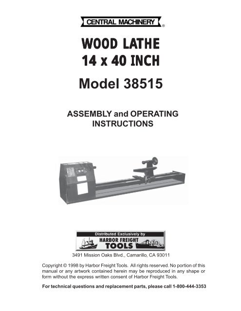
WOOD LATHE<br />
14 x 40 INCH<br />
Model 38515<br />
ASSEMBLY and OPERATING<br />
INSTRUCTIONS<br />
3491 Mission Oaks Blvd., Camarillo, CA 93011<br />
Copyright © 1998 by <strong>Harbor</strong> <strong>Freight</strong> <strong>Tools</strong>. All rights reserved. No portion of this<br />
manual or any artwork contained herein may be reproduced in any shape or<br />
form without the express written consent of <strong>Harbor</strong> <strong>Freight</strong> <strong>Tools</strong>.<br />
For technical questions and replacement parts, please call 1-800-444-3353
Specifications<br />
Motor<br />
Input Voltage<br />
Spindle<br />
Max.<br />
Max.<br />
Swing<br />
Distance<br />
ITEM<br />
Rotation Speed<br />
Stock Diameter<br />
Stock Length<br />
Over Bed<br />
Between Centers<br />
DESCRIPTIO N<br />
1/2 Horsepower; 3010 RPM<br />
110 VAC, single phase,<br />
60 Hz, 5 amps, 550 Watts<br />
1020 to 3010 RPM; belt driven<br />
14 inches<br />
40 inches<br />
14 inches<br />
40 inches<br />
H ead Stock Thread 3/4"-10 T.P.I. "<br />
Dimensions<br />
56-1/2 x 8-1/4 x<br />
12-3/4 inches<br />
Save This Manual<br />
You will need the manual for the safety warnings and precautions, assembly instructions,<br />
operating and maintenance procedures, parts list and diagram. Keep your invoice with this<br />
manual. Write the invoice number on the inside of the front cover. Keep the manual and<br />
invoice in a safe and dry place for future reference.<br />
Safety Warnings and Precautions<br />
WARNING: When using tool, basic safety precautions should always be<br />
followed to reduce the risk of personal injury and damage to equipment.<br />
Read all instructions before using this tool!<br />
1. Do not force tool. It will do the job better and more safely at the rate for which it was<br />
intended. Do not use inappropriate attachments in an attempt to exceed the tool’s<br />
capacities.<br />
2. Use the right tool for the right job. Do not attempt to force a small tool or<br />
attachment to do the work of a larger industrial tool. Do not use a tool for a purpose<br />
for which it was not intended.<br />
3. Avoid working alone. If an accident happens, an assistant can bring help.<br />
4. Avoid electrical shock. Prevent body contact with grounded surfaces such as pipes,<br />
radiators, ranges, and cabinet enclosures when connecting power.<br />
5. Keep work area clean. Cluttered areas invite injuries.<br />
6. Avoid damaging tool. Use only as specified in this manual.<br />
SKU 38515<br />
Page 2<br />
REV 02/01
7. Observe work area conditions. Do not use machines or power tools in damp or wet<br />
locations. Don’t expose to rain. Keep work area well lighted. Do not use electrically<br />
powered tools in the presence of flammable gases or liquids.<br />
8. Keep children away. Children must never be allowed in the work area. Do not let<br />
them handle machines, tools, or extensions cords.<br />
9. Store idle equipment. When not in use, tools must be stored in a dry location to inhibit<br />
rust. Always lock up tools and keep out of reach of children.<br />
10. Dress properly. Do not wear loose clothing or jewelry as they can be caught in<br />
moving parts. Protective, electrically nonconductive clothes and nonskid footwear are<br />
recommended when working. Wear restrictive hair covering to contain long hair.<br />
11. Use eye and ear protection. Always wear ANSI approved impact safety goggles.<br />
12. Keep guards and cover in place and in working order.<br />
13. Avoid unintentional starting. Be sure the switch is in the Off position when not in use<br />
and before plugging in. Do not carry any tool with your finger on the trigger, whether it<br />
is plugged in or not.<br />
14. Do not abuse the power cord. Do not yank compressor’s cord to disconnect it from<br />
the receptacle. Do not carry tools by the cord.<br />
15. Remove adjusting keys and wrenches. Check that keys and adjusting wrenches<br />
are removed from the tool or machine work surface before plugging it in.<br />
16. Avoid unintentional starting. Be sure the switch is in the Off position when not in<br />
use and before plugging in.<br />
17. Do not overreach. Keep proper footing and balance at all times. Do not reach over<br />
or across electrical cables or frames.<br />
18. Maintain tools with care. Inspect tool cords periodically and, if damaged, have them<br />
repaired by an authorized technician.<br />
19. Outdoor extension cords. When the equipment is operated outdoors, use only<br />
extension cords intended for outside use.<br />
20. Stay alert. Watch what you are doing, use common sense. Do not operate any tool<br />
when you are tired.<br />
21. Replacement parts and accessories. When servicing, use only identical<br />
replacement parts. Use of any other parts will void the warranty. Only use<br />
accessories intended for use with this tool. Approved accessories are available from<br />
<strong>Harbor</strong> <strong>Freight</strong> <strong>Tools</strong>.<br />
22. Check for damaged parts. Before using any tool, any part that appears damaged<br />
should be carefully checked to determine that it will operate properly and perform its<br />
intended function. Check for alignment and binding of moving parts; any broken parts<br />
or mounting fixtures; and any other condition that may affect proper operation. Any<br />
part that is damaged should be properly repaired or replaced by a qualified<br />
technician. Do not use the tool if any switch does not turn On and Off properly.<br />
SKU 38515<br />
Page 3
23. Do not operate tool if under the influence of alcohol or drugs. Read warning<br />
labels on prescriptions to determine if your judgment or reflexes are impaired while<br />
taking drugs. If there is any doubt, do not operate the tool<br />
Unpacking<br />
When unpacking, check to make sure that all parts are included (refer to Parts List and<br />
Diagram at end of manual). The plastic bag with parts includes the 5 parts shown with * on<br />
the Parts List. If any parts are missing or broken, please call <strong>Harbor</strong> <strong>Freight</strong> <strong>Tools</strong> at the<br />
number on the cover of this manual.<br />
Extension Cords<br />
This machine has a three prong plug and must only be plugged into three prong receptacles.<br />
Never cut off the round prong, this is the ground. Cutting off the ground will result<br />
in a safety hazard and void the warranty.<br />
The three prong plug must only be used with a three prong extension cord. Only use<br />
rounded jacket extension cords listed by the Underwriters Laboratories (UL). If you are<br />
using the tool outdoors, you must use an extension cord rated for outdoor use. Look on<br />
the jacket for the letters “WA”.<br />
Mounting <strong>Lathe</strong> to Workbench<br />
1. Measure the thickness of your workbench.<br />
2. Obtain four bolts that are the lengths for the workbench, and 1 inch for the wood lathe.<br />
Make sure that nuts and flat washers are also obtained.<br />
3. Mark and drill holes through the workbench, using the <strong>Lathe</strong> Bed (58) as a template,<br />
for the four mounting holes on the <strong>Wood</strong> <strong>Lathe</strong>.<br />
4. Position the <strong>Wood</strong> <strong>Lathe</strong> on your workbench and line up the holes you drilled in Step 3<br />
with the Mounting holes in the <strong>Lathe</strong> Bed (58).<br />
5. Insert bolts into the Mounting Holes and through the work bench.<br />
6. Tighten down bolts using nuts and washers.<br />
Power Switch (30)<br />
<strong>Lathe</strong> Tip (28)<br />
Tip (37)<br />
Handwheel (43)<br />
Jip (33)<br />
Tool Carriage (35)<br />
SKU 38515<br />
Page 4<br />
Rev 10/00
Finding the Center of the <strong>Wood</strong> Stock<br />
Operation<br />
Use only fresh, square lengths of wood stock or stock that has clearly defined center points<br />
on each end of the stock. Follow the Steps below to find the center of the wood stock.<br />
1. Draw two diagonal lines across each end of the wood stock, from one corner to the<br />
other corner.<br />
2. The point where the two lines cross is the center of the wood stock. Mark this point<br />
with an awl or drill.<br />
Mounting the <strong>Wood</strong> Stock<br />
1. Make sure the length or your wood stock does not exceed the capacity of the <strong>Wood</strong><br />
<strong>Lathe</strong>. The maximum length or your wood stock should not exceed 40 inches.<br />
2. Adjust the Handwheel (43) so that the threads of the Screw Axis (41) are halfway on<br />
each side of the Tailstock (39). This will allow the most fore and aft adjustment in the<br />
following steps.<br />
3. Adjust the position of the Tailstock to fit the length of your wood stock. Use the<br />
supplied Tool Handle (22) to loosen the Nut (54) underneath the Tailstock.<br />
4. Move the Tailstock to the appropriate location. Tighten the Nut (54).<br />
5. Place your wood stock between the Tip (37) and the <strong>Lathe</strong> Tip (28). Make sure the<br />
<strong>Lathe</strong> Tip is placed in the center point of your wood stock that was marked earlier.<br />
6. Turn the Handwheel (43) clockwise until the Tip (37) touches the end of your wood<br />
stock. Adjust the wood stock so the Tip is touching the center point of your wood<br />
stock marked earlier.<br />
7. Continue to turn the Handwheel to mount your wood stock. Stop tightening the<br />
Handwheel when the <strong>Lathe</strong> Tip prongs dig into the wood stock fully.<br />
8. Grip the wood stock and try to move it. The wood stock should be mounted firmly<br />
and not move at all.<br />
Positioning the Tool Rest<br />
1. Use the Tool Handle (22) to loosen the Nut (61) located underneath the Tool Carriage<br />
(35).<br />
2. Move the Tool Carriage to the appropriate position. If you are beginning a new piece<br />
of wood stock, choose an end to start and adjust the Tool Carriage to that location<br />
and tighten the Nut (61) again.<br />
4. Loosen the Knob (59) for the Tool Carriage. This will allow you to adjust the Tool<br />
Carriage height and degree of rotation. To begin, set the Tool Carriage even with the<br />
centerline of the wood stock and parallel to the wood stock centerline.<br />
5. Tighten the Knob.<br />
SKU 38515<br />
Page 5
Turning the <strong>Wood</strong> Stock<br />
Caution: Before turning on the <strong>Wood</strong> <strong>Lathe</strong>, make sure to wear ANSI<br />
approved eye protection, and do not have any loose clothing or long hair<br />
exposed.<br />
1. Lay out your selection of gouges and chisels. You may wish to mark indicator lines<br />
along the length of the wood stock to mark points of transition or design change.<br />
2. Plug the <strong>Wood</strong> <strong>Lathe</strong> Power Line (1) into an appropriate outlet.<br />
3. Turn on the <strong>Wood</strong> Lath by pressing the Power Switch (30) to “ON” and allow it to<br />
come up to speed.<br />
Caution: If the wood stock begins to wobble or is unstable, immediately<br />
turn lathe OFF and reposition wood stock.<br />
4. Place the desired gouge or chisel onto the Tool Carriage (35). Make sure the cutting<br />
edge of the gouge or chisel is oriented properly for the <strong>Wood</strong> <strong>Lathe</strong> direction of<br />
rotation.<br />
5. Gently press the gouge or chisel forward into the spinning wood stock. Move the tool<br />
forward in small increments. This is especially important with a fresh, square piece of<br />
wood stock.<br />
6. If you press the gouge or chisel forward too fast, you may cause the <strong>Wood</strong> <strong>Lathe</strong> to<br />
stall. The spinning wood stock may also knock the tool from your hand. Use<br />
Caution.<br />
7. Move the gouge or chisel slowly up and down the length of the Tool Carriage to shape<br />
the wood stock. When shaping the wood stock, use patience and care. Do not force<br />
the tool into the wood stock or try to take too great an amount of wood off at one<br />
time.<br />
8. When the wood stock has been roughly shaped for part of its length, you can move<br />
the Tool Carriage to the section of the unshaped wood.<br />
9. When the entire length or wood stock has been roughly formed into a cylindrical<br />
shape, you can switch to your final shaping and decorating gouges and chisels.<br />
10. When you are done shaping your wood stock, turn the Power Switch (30) to “OFF”.<br />
11 Turn the Handwheel (43) counterclockwise and removed the shaped wood stock.<br />
Using the Chuck<br />
For the following steps you need a piece of wood stock 1 inch thick by at least five inches in<br />
diameter<br />
1. Attach your wood stock piece to the Chuck (29) using wood screws inserted through<br />
the back of the Chuck into the wood Stock.<br />
2. Attach the chuck as described under Adjustments below.<br />
3. Turn the wood stock until it is completely circular and slightly larger in diameter than<br />
the Chuck.<br />
SKU 38515<br />
Page 6
Adjustments<br />
Refer to the Assembly Drawing on the last page to find parts referenced below.<br />
Moving the Tailstock and Tool Carriage<br />
1. Make sure <strong>Lathe</strong> Power Line (1) is disconnected.<br />
2. Loosen the Nut (61) for the Tool Carriage (35), or the Nut (54) to move the Tailstock<br />
(39).<br />
3. Slide the Tool Carriage or the Tailstock to the appropriate position and then retighten<br />
the corresponding nut.<br />
Removing the Tip<br />
1. Make sure <strong>Lathe</strong> Power Line (1) is disconnected.<br />
2. Remove the Handwheel (43) by loosening the Locking Screw (42).<br />
3. Unscrew the Tip (37) from the Tailstock (39)<br />
Removing the <strong>Lathe</strong> Tip<br />
1. Place the side fitting of the Tool Handle (22) onto the flats of the Main Shaft (27).<br />
2. Attach an appropriately sized wrench to the <strong>Lathe</strong> Tip (28).<br />
3. While holding the Tool Handle (22) in place, turn the <strong>Lathe</strong> Tip counterclockwise.<br />
Remove the loosened <strong>Lathe</strong> Tip from the Main Shaft (27).<br />
Tool Handle (22)<br />
Main Shaft (27)<br />
<strong>Lathe</strong> Tip (28)<br />
Attaching the Chuck<br />
1. After the <strong>Lathe</strong> Tip has been removed (see above), take the Chuck (29) and spin it<br />
clockwise onto the Main Shaft (27).<br />
2. Hold the Tool Handle (22) in place on the flats of the Main Shaft, while tightening the<br />
Chuck by hand.<br />
SKU 38515<br />
Page 7
Main Shaft (27)<br />
Chuck (29)<br />
Aligning the Centers<br />
1. Move the Tailstock (39) to the <strong>Lathe</strong> Tip (28).<br />
2. Lock the Tailstock down.<br />
3. Loosen the four screws (26), around the Main Shaft (27).<br />
4. Swing the Main Shaft forward so the <strong>Lathe</strong> Tip (28) and the Tip (37) are in line. Then<br />
tighten the Screws (26).<br />
Screws (26)<br />
Tip (37)<br />
TailStock (39)<br />
Main Shaft (27)<br />
<strong>Lathe</strong> Tip (28)<br />
Changing Speeds<br />
Refer to photo and illustration on the next page.<br />
1. Make sure the Power Switch (30) is off and the Power Line (1) is unplugged.<br />
2. Remove the two Screws (3) from the Protecting Cover (11). Remove the Protecting<br />
Cover.<br />
3. Loosen the Motor Screw (14) this will loosen the Belt Pulley (13).<br />
4. Raise the lower Belt Pulley (13) this will loosen the Driving Belt (12).<br />
SKU 38515<br />
Page 8
Upper Belt Pulley (5)<br />
Power Switch (30)<br />
Driving Belt (12)<br />
Motor Screw (14)<br />
Protecting Cover (11)<br />
Lower Belt Pulley (13)<br />
5. Adjust the Driving Belt (12) to the proper steps on the lower Belt Pulley (13) and the<br />
upper Belt Pulley (5) to obtain the desired speed. Make sure Driving Belt is not<br />
crossed into the adjacent steps. The Driving Belt should be placed on the same step<br />
on each Belt Pulley.<br />
Upper Belt Pulley (5)<br />
Lower Belt Pulley (13)<br />
6. Lower the Belt Pulley (13) until there is a light tension on the Driving Belt (12). Tighten<br />
the Motor Screw (14). Make sure the Driving Belt is neither too loose nor too tight.<br />
7. Close the Protecting Cover (11) and insert and tighten the Screws (3).<br />
SKU 38515<br />
Page 9
Maintenance<br />
When you are finished using your <strong>Wood</strong> <strong>Lathe</strong> for the day, wipe down the <strong>Wood</strong> <strong>Lathe</strong> or<br />
use an air compressor set at 10 PSI to blow the <strong>Wood</strong> <strong>Lathe</strong> clean.<br />
Periodically check your <strong>Wood</strong> <strong>Lathe</strong> for wear or damage and inspect the Driving Belt (12).<br />
Do not use your <strong>Wood</strong> <strong>Lathe</strong> if you find any damage or wear.<br />
SKU 38515<br />
Page 10
Item #<br />
Descriptio<br />
n<br />
Qty<br />
1 Power<br />
Line<br />
1<br />
2 Cord<br />
Clamp<br />
1<br />
3 Screw<br />
3<br />
4 Washer<br />
3<br />
5 Belt<br />
Pulley<br />
1<br />
6 Locking<br />
Screw *<br />
1<br />
7 Bolt<br />
1<br />
8 Washer<br />
1<br />
9 Screw<br />
1<br />
10<br />
Washer<br />
2<br />
11<br />
Protective<br />
Cover<br />
1<br />
12<br />
Driving<br />
Belt<br />
1<br />
13<br />
Belt<br />
Pulley<br />
1<br />
14<br />
Motor<br />
Screw<br />
1<br />
15<br />
Washer<br />
1<br />
16<br />
Locking<br />
Screw *<br />
2<br />
17<br />
Screw<br />
2<br />
18<br />
Washer<br />
2<br />
19<br />
Ball<br />
Bearing<br />
1<br />
20<br />
Bearing<br />
Lock<br />
1<br />
21<br />
Nut<br />
1<br />
22<br />
Tool<br />
Handle *<br />
1<br />
23<br />
Bearing<br />
Lock<br />
1<br />
24<br />
Ball<br />
Bearing<br />
1<br />
25<br />
Washer<br />
1<br />
26<br />
Screw<br />
1<br />
27<br />
Main<br />
Shaft<br />
1<br />
28<br />
<strong>Lathe</strong><br />
Tip<br />
1<br />
29<br />
Chuck<br />
*<br />
1<br />
30<br />
Power<br />
Switch<br />
1<br />
31<br />
Washer<br />
2<br />
32<br />
Screw<br />
2<br />
33<br />
Jip<br />
1<br />
34<br />
Cap<br />
Screw<br />
1<br />
35<br />
Tool<br />
Carriage<br />
1<br />
36<br />
Guide<br />
Trac k<br />
2<br />
37<br />
Tip<br />
1<br />
Parts List<br />
Item #<br />
8<br />
Descriptio<br />
n<br />
Qty<br />
3 Ball<br />
Bearing<br />
1<br />
39<br />
Tailstoc<br />
k<br />
1<br />
40<br />
Nut<br />
1<br />
41<br />
Screw Axis<br />
1<br />
42<br />
Locking<br />
Screw<br />
1<br />
43<br />
Handwhee<br />
l<br />
1<br />
44<br />
Screw<br />
2<br />
45<br />
Washer<br />
2<br />
46<br />
Bracke<br />
t<br />
1<br />
47<br />
Screw<br />
2<br />
48<br />
Washer<br />
2<br />
49<br />
Cap<br />
Screw<br />
1<br />
50<br />
Washer<br />
2<br />
51<br />
Spring<br />
Washer<br />
2<br />
52<br />
Nut<br />
2<br />
53<br />
Guide<br />
Track Plate<br />
1<br />
54<br />
Nut<br />
1<br />
55<br />
Washer<br />
2<br />
56<br />
Spring<br />
Washer<br />
2<br />
57<br />
Nut<br />
2<br />
58<br />
<strong>Lathe</strong><br />
Bed<br />
1<br />
59<br />
Knob<br />
1<br />
60<br />
Guide<br />
Track Plate<br />
1<br />
61<br />
Nut<br />
1<br />
62<br />
Washer<br />
2<br />
63<br />
Spring<br />
Washer<br />
2<br />
64<br />
Nut<br />
2<br />
65<br />
Screw - Switch<br />
2<br />
66<br />
Screw<br />
1<br />
67<br />
Washer<br />
1<br />
68<br />
Data<br />
Plate<br />
1<br />
69<br />
Washer<br />
2<br />
70<br />
Spring<br />
Washer<br />
2<br />
71<br />
Nut<br />
2<br />
72<br />
Motor<br />
1<br />
73<br />
Washer<br />
2<br />
74<br />
Spring<br />
Washer<br />
2<br />
75<br />
Hexagonal<br />
Wrench *<br />
1<br />
Note: 5 items included in plastic packaging bag designated with *.<br />
SKU 38515<br />
Page 11<br />
Rev 10/00
Assembly Drawing<br />
SKU 38515<br />
Page 12