29416 Graepel TH engl. neu:Inhalt - Friedrich Graepel AG
29416 Graepel TH engl. neu:Inhalt - Friedrich Graepel AG
29416 Graepel TH engl. neu:Inhalt - Friedrich Graepel AG

Create successful ePaper yourself
Turn your PDF publications into a flip-book with our unique Google optimized e-Paper software.
Load types<br />
Preliminary remarks to the table<br />
on the following pages<br />
The metal profile gratings are dimensioned for the<br />
elastic material region. In this, either dimensions<br />
are taken considering the permissible stress of the<br />
material or considering the permissible deflection.<br />
The table values always consider the least<br />
advantageous value.<br />
The permissible deflection of the “metalprofile<br />
grating” beam is L/200, where L is the support<br />
width.<br />
In the case that greater deflections are permitted,<br />
then the deflection is to be calculated with the aid<br />
of the areal moment of inertia of the individual<br />
grating type according to the normal structural<br />
calculations.<br />
For gratings lying next to each other, the deflection<br />
of the loaded individual gratings must be bolted<br />
together. A bolt spacing of approximately 500 mm<br />
recommended.<br />
The following loads can occur.<br />
a) vertikal on the surface of the grating effective<br />
2<br />
uniformly distributed load in kN/m<br />
b) effective vertical concentrated load in kN<br />
effective over the whole grating width distributed<br />
on a surface area of B x 0,2 m. Here the concentrated<br />
load is to be placed in the most disadvantageous<br />
position.<br />
c) effective vertical lump load in kN acting on a<br />
surface area of a 1x a 2. The sizes of the loads and<br />
the long effective surface can be determined from<br />
DIN 1055 sheet 3 or DIN 1072.<br />
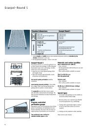
Uniformly distributed load<br />
Only the unperforated area of the two sides is taken in<br />
account. In the static cross section values for the long direction<br />
of the grating.<br />
Concentrated load<br />
Lump load<br />
Determination of the permissible uniformly<br />
distributed load<br />
Conversation of the replacement load Fq<br />
from the table into an uniformly distributed<br />
load Q:<br />
10 6 xFq<br />
Q =<br />
whereaby:<br />
B x L<br />
Q = Distributed load for a grating [in kN/m 2 ]<br />
Fq= Replacement load from table with reference<br />
to the support width [in kN]<br />
B = Grating width [in mm]<br />
L = Support length [in mm]<br />
Calculation example: (dimensions in mm)<br />
Material: DD 11 Material thickness: S = 2.5<br />
Edge height: H = 40 Support length: L = 1250<br />
Table value: Fq = 2.52 kN<br />
Grating width B = 240 mm<br />
10 6 x2.52<br />
Q =<br />
240 x 1250<br />
= 8.40 kN/m 2<br />
Determination of the permissible<br />
concentrated load<br />
The value of the permissible concentrated load<br />
with reference to the material, material thickness,<br />
edge height and support width can be read directly<br />
from the tables.<br />
This assumes that the load surface acts over the<br />
whole grating width B then the load values of the<br />
table “lump load” must not be exceeded. Decisive<br />
is the lower value.<br />
Load increases<br />
1. When placing the grating over serveral supports<br />
(continuous beam), the permissible loads can be<br />
increased according to normal structural calculations.<br />
2. If the gratings are bolted together such that the<br />
load only acts on the middle grating, then the<br />
permissible load values from the table can be<br />
doubled.<br />
5