COPPER CASTING ALLOYS - Copper Development Association
COPPER CASTING ALLOYS - Copper Development Association
COPPER CASTING ALLOYS - Copper Development Association

Create successful ePaper yourself
Turn your PDF publications into a flip-book with our unique Google optimized e-Paper software.
<strong>COPPER</strong> <strong>CASTING</strong> <strong>ALLOYS</strong><br />
(hiTl)<br />
Non-Ferrous Founders' Society<br />
~CDA<br />
<strong>Copper</strong> <strong>Development</strong> <strong>Association</strong>
<strong>COPPER</strong> <strong>CASTING</strong> <strong>ALLOYS</strong><br />
PREFACE ................................................................ . . .......................... ..4<br />
FIGURES: FIGURES P-l to P-4. Typical <strong>Copper</strong> Casting Applications ................................................................. 5<br />
UNDERSTANDING <strong>COPPER</strong> <strong>CASTING</strong> <strong>ALLOYS</strong><br />
I. CLASSIFYING THE <strong>COPPER</strong> <strong>ALLOYS</strong>. .............. 7<br />
Common Classification Systems .......................... .<br />
TABLES:<br />
The UNS Numberi ng System ..................... .................................. .......................................... 7<br />
The <strong>Copper</strong> Metal Families: Classification and Major Uses ..................... .. ............................ 7<br />
Metallurgy and Foundry Charactel;stics ............................... 10<br />
Effects of Lead .... . ................................................ .............. ................................ ............................. 11<br />
Alloy Characteristics<br />
TABLE I. Standard Temper Designations for <strong>Copper</strong> Casting Alloys ....................... . . ............................. 8<br />
TABLE 2. Overview of <strong>Copper</strong> Casting Alloys ........................ . .. ........................ 12<br />
TABLE 3. Typical Mechanical Properties of <strong>Copper</strong> Casting Alloys .......... ......... . .. .......................... 26<br />
TABLE 4. Physical Properties of <strong>Copper</strong> Casting Alloys. . ...... ..42<br />
TABLE 5. Conforming Specifications for <strong>Copper</strong> Casting Alloys ..... .. ......47<br />
FIGURES: FlGURES I-I to 1-3. Representative <strong>Copper</strong> Alloy Castings .. . ........................................ 25<br />
FIGURES 1-4 to 1-10. Representative <strong>Copper</strong> Alloy Castings ................ . . ... ................ ......... ... ...... .52,53<br />
SELECTING <strong>COPPER</strong> <strong>CASTING</strong> <strong>ALLOYS</strong><br />
II. SELECTING <strong>COPPER</strong> <strong>ALLOYS</strong> FOR CORROSION RESISTANCE .............................................................. .55<br />
Fonns of Corrosion in <strong>Copper</strong> Alloys ...................................................................................... . .. .. 55<br />
Selecting Alloys for Corrosive Environments .................... ............... ............................................................ 57<br />
TABLE: TABLE 6. Velocity Guidelines for <strong>Copper</strong> Alloys in Pumps and Propellers in Seawater. .. ...... 6 1<br />
FIGURES: FlGURES 11-1,11-2. Decreasing corrosion rate over time of Cu-Ni in Seawater. ............................. 61<br />
FIGURE 11-3. Galvanic Series Chart ............................................................................................................. 62<br />
III. SELECTING <strong>COPPER</strong> <strong>ALLOYS</strong> FOR MECHANICAL PROPERTIES . ................ .<br />
Strength ........................................... .<br />
Strength and Temperature .................. .<br />
Friction and Wear .................................... ...... .......................................... . ................................... .<br />
Fatigue Strength ...................................................................................................... .. .. ............................. 64<br />
FIGURES: FIGURES III-I to III-7. Effect of Temperature on Various Mechanical Properties<br />
for Selected Alloys................... .................................... ............. ........... .. .................................... 65-68<br />
.... 63<br />
. ... 63<br />
..63<br />
... 64<br />
Non-Ferrous Founders' Society<br />
455 State Street· Des Plaines, IL 60016<br />
~ CDA<br />
<strong>Copper</strong> <strong>Development</strong> <strong>Association</strong><br />
260 Madison Avenue· New York, NY 10016
TABLE OF CONTENTS\continued<br />
IV. SELECTING <strong>COPPER</strong> <strong>ALLOYS</strong> FOR PHYSICAL PROPERTIES . ... ... ........ ..................... ......... 69<br />
Electrical Conductivity ................. . .................. 69<br />
Thermal Conductivity ........ ..... .. .... .. .. .. ................. .............. .... .................................. 69<br />
FIGURES: FIGURES IV-I, JV-2. Temperature dependence of electrical and thermal conductivity for selected<br />
copper casting alloys ...<br />
V.<br />
TABLES:<br />
SELECTING <strong>COPPER</strong> <strong>ALLOYS</strong> FOR FABRICABILITY . ................. .<br />
Machinabi lity ..<br />
Weldability ....<br />
Brazing, Soldering ......... .<br />
Alloy Selection Criteria<br />
. ........................................................................................................ W<br />
. .................. 71<br />
. ................. 71<br />
....... 71<br />
.......................................................................................... TI<br />
TABLE 7. Corrosion Ratings of <strong>Copper</strong> Casting Alloys in Various Media ......... . ...... 73<br />
TABLE 8. <strong>Copper</strong> Casting Alloys Ranked by Typical Tensile Strength ........ . . ..... 76<br />
TABLE 9. <strong>Copper</strong> Casting Alloys Ranked by Typical Yield Strength ... . ....... 78<br />
TABLE 10. <strong>Copper</strong> Casti ng Alloys Ranked by Compressive Strength ............... ... ....................................... 80<br />
TABLE II. Impact Properties of <strong>Copper</strong> Casting Alloys at Various Temperatures. . ... ... .......... ......... ....... 81<br />
TABLE 12. Creep Strengths of Selected Sand-Cast <strong>Copper</strong> Alloys.......................... . ............ 82<br />
TABLE 13. Stress-Rupture Properties of Selected <strong>Copper</strong> Casting Alloys .... . ...... 83<br />
TABLE 14. Common Bronze Bearing Alloys ... ............. . . .............. 84<br />
TABLE 15. Fatigue Properties of Selected <strong>Copper</strong> Casting Alloys ....... 85<br />
TABLE 16. <strong>Copper</strong> Casting Alloys Ranked by Electrical Conductivity .... .... ... ........... ... ........ .................. 86<br />
TABLE 17. <strong>Copper</strong> Casting Alloys Ranked by Thermal Conductivity .................. 87<br />
TABLE 18. <strong>Copper</strong> Casting Alloys Ranked by Machinability Rating ........ 88<br />
TABLE 19. Joining Characteristics of Selected <strong>Copper</strong> Casti ng Alloys ...................................... 89<br />
TABLE 20. Technical Factors in the Choice of Casting Method for <strong>Copper</strong> Alloys ................................... 9 1<br />
FIGURES: FIGURES V- I, V-2. Examples of Welded Cast Structures ............... .... ......................... . . .............. 70<br />
WORKING WITH <strong>COPPER</strong> <strong>CASTING</strong> <strong>ALLOYS</strong><br />
VI. <strong>CASTING</strong> PROCESSES. ..... .......... ....... 93<br />
Processes for General Shapes ... . ............................... ... ............ ... ... ...... .......... ....................... 93<br />
Processes for Specific Shapes ................ . . ... 96<br />
Special Casting Processes ..... . . . .......... 96<br />
Selecting a Casting Process .................................................... . ... 97
FIGURES: FIGURES VI-Ia,b. Sand Casting ................................ .................. . ........................................................................... 98<br />
FIGURES VI-2a,b. Shell Molding .................................................................................................................... 99<br />
FIGURES VI-3a,b. Investment Casting ................................................................................................... 100,101<br />
FIGURES VI-4a,b,c. Pennanent Mold ........................................................................................................... 101<br />
FIGURES VI-5a,b. Die Casting ...................................................................................................................... 102<br />
FIGURES VI-6a,b. Continuous Casting ......................................................................................................... 1 03<br />
FIGURES VI-7a,b,c. Centrifugal Casting ....................................................................................................... 1 03<br />
VII. <strong>CASTING</strong> DESIGN PRINCiPLES .. .......................................................................................................... 104<br />
Design Fundamentals ....................................................................................................................................... 1 04<br />
FIGURES: FIGURES Vll-I to Vll4. Casting Design Considerations ..................................................................... 106,107<br />
SPECIFYING AND BUYING <strong>COPPER</strong> <strong>CASTING</strong> AllOYS<br />
VIII. ORDERING A <strong>COPPER</strong> ALLOY <strong>CASTING</strong> ............................................................................................ 109<br />
Sample Purchase Order for a Sand Casting .................................................................................................... 110<br />
REFERENCES ................................................................................................................................................ 111<br />
Published 1994 by <strong>Copper</strong> <strong>Development</strong> <strong>Association</strong> Inc., 260 Madison A venue, New York, NY 10016<br />
PHOTOGRAPHY ACKNOWLEDGMENTS<br />
We wish to thank the following for providing photography or the items used for photography in this publication.<br />
Ampco Metal , Inc.<br />
Brush Wellman<br />
Birkett<br />
Canadian <strong>Copper</strong> & Brass <strong>Development</strong> <strong>Association</strong><br />
Hayward Tyler Fluid Dynamics Ltd.<br />
J.W. Singer & Sons, Ltd.<br />
Southern Centrifugal<br />
Square D Company<br />
Stone Manganese Marine<br />
Westley Brothers<br />
Wisconsin Centrifugal<br />
This Handbook has been prepared for the use of engineers, designers and purchasing managers involved in the selection,<br />
design or machining of copper rod alloys. It has been compiled from infonnation supplied by testing, research, manufacturing,<br />
standards, and consulting organizations that <strong>Copper</strong> <strong>Development</strong> <strong>Association</strong> Inc. believes to be competent sources for such<br />
data. However, CDA assumes no responsibility or liability of any kind in connection with the Handbook or its use by any<br />
person or organization and makes no representations or warranties of any kind thereby_<br />
70t4-0009
PREFACE<br />
This guide was prepared for individuals<br />
who select, specify and buy<br />
materials for cast copper alloy products.<br />
Its purpose is to help engineers, designers<br />
and purchasing agents understand<br />
copper alloys so they can choose the<br />
most suitable and most economical<br />
material to meet their product's requirements.<br />
There have been several excellent<br />
texts on copper casting alloys published<br />
in recent years, 1.! but these were written<br />
more for the foundry operator than for<br />
designers. engineers and purchasing<br />
agents. The collections of technical data<br />
on cast copper alloys that were published<br />
in the 1960s,' 1 970s' and as<br />
recently as 1990' are either out of print<br />
or have not been widely distributed. As<br />
a result, few individuals are fully aware<br />
of all the technical, economic and practical<br />
advantages that the large family of<br />
copper alloys has to offer. The present<br />
guide, written specifically for the design<br />
community, was prepared to fill this<br />
information gap.<br />
Why Specify Cast <strong>Copper</strong> Alloys?<br />
Cast copper alloys have an<br />
extremely broad range of application.<br />
They are used in virtually every industrial<br />
market category, from ordinary plumbing<br />
goods to precision electronic components<br />
and state-of-the-art marine and nuclear<br />
equipment. Their favorable properties are<br />
often available in useful combinations.<br />
This is particularly valuable when, as is<br />
usually the case, a product must satisfY<br />
several requirements simultaneously.<br />
The following properties are the<br />
reasons cast copper alloys are most often<br />
selected:<br />
Excellent Corrosion Resistance.<br />
The ability to withstand corrosive<br />
environments is the cast copper<br />
alloys' most important and bestknown<br />
characteristic. The alloys<br />
have a natural corrosion resistance,<br />
making durability without maintenance<br />
an important element of their<br />
long-term cost-effectiveness.<br />
Not surprisingly, water handling<br />
equipment of one form or<br />
another constitutes the cast alloys'<br />
largest single market. <strong>Copper</strong> alloy<br />
castings are also widely used to handle<br />
corrosive industrial and process<br />
chemicals, and they are well known<br />
in the food, beverage and dairy<br />
industries. Figure P-l shows several<br />
aluminum bronze pickJing hooks<br />
used to immerse coi ls of steel wire<br />
in hot, dilute sulfuric acid.<br />
Favorable Mechanical Properties.<br />
Pure copper is soft and ductile, and it<br />
is understandably used more often<br />
for its high conductivity than for its<br />
mechanical strength. Some cast copper<br />
alloys, on the other hand, have<br />
strengths that rival quenched and<br />
tempered steel s.<br />
Almost all copper alloys retain<br />
their mechanical properties, including<br />
impact toughness. at very low<br />
temperatures. Other alloys are used<br />
routinely at temperatures as high as<br />
800 F (425 C). No class of engineering<br />
materials can match the copper<br />
alloys' combination of strength,<br />
corrosion resistance and thermal<br />
and electrical conductivities over<br />
such a broad temperature range.<br />
Friction and Wear Properties.<br />
Cast sleeve bearings are an important<br />
application for copper alloys,<br />
largely because of their excellent tribological<br />
properties. For sleeve bearings.<br />
no material of comparable<br />
strength can match high leaded<br />
bronzes in terms of low wear rates<br />
against steel. For worm gears, nickel<br />
bronzes and tin bronzes are industry<br />
standards.<br />
Equally important, the copper<br />
alloys' broad range of mechanical<br />
properties enables the designer to<br />
match a specific alloy wi th a bearing's<br />
precise operating requirements.<br />
Cast sleeve bearings are shown in<br />
Figure P-2. A comprehensive discussion<br />
of copper bearing alloys can<br />
be found in the CDA publication,<br />
Cast Bronze Bearings - Alloy<br />
Selection and Bearing Design<br />
Biofouling Resistance. <strong>Copper</strong> effectively<br />
inhibits algae, barnacles and<br />
other marine organisms from attaching<br />
themselves to submerged surfaces.<br />
Nonfouling behavior is highest in pure<br />
copper and high copper alloys, but it is<br />
also strong in the alloys used in marine<br />
service. Products such as seawater piping,<br />
pumps and valves made from copper<br />
alloys therefore remain free from<br />
biomass buildup and are able to operate<br />
continuously without the periodic<br />
cleanup needed with steel, rubber or<br />
fiber-reinforced plastic products.<br />
High Electrical and Thermal<br />
Conductivity. <strong>Copper</strong>'s electrical<br />
and thermal conductivities are higher<br />
than any other metal' s except silver.<br />
Even copper alloys with relatively<br />
low conductivities compared with<br />
pure copper conduct heat and electricity<br />
far better than other structural<br />
metals such as stainless steels and<br />
titanium.<br />
Unlike most other metals, the<br />
thermal conductivity of many copper<br />
casting alloys increases with rising<br />
temperature. This can improve the<br />
efficiency of copper alloy heat<br />
exchangers. Electrical conductivity<br />
generally decreases with increasing<br />
4
alloy content, but even relatively<br />
highly alloyed brasses and bronzes<br />
retain sufficient conductivity for use<br />
as electrical hardware. For example,<br />
the hot-line clamp shown in Figure<br />
P-3 is made from Alloy C84400, a<br />
leaded semi-red brass whose electrical<br />
conductivity is only 16% that of<br />
pure copper. Nevertheless, the alloy<br />
has the proper combination of<br />
strength and conductiv ity required<br />
for this safety- related application.<br />
Other characteristics of the<br />
copper casting alloys can make products<br />
simpler and less costly to produce.<br />
For example:<br />
Good Castability. All copper alloys<br />
can be sand cast. Many compositions<br />
can also be specified for permanent<br />
mold, plaster, precision and die castings,<br />
wh ile continuous casting and<br />
centrifugal casting are applicable to<br />
virtually all of the copper alloys.<br />
With such a wide choice of<br />
processes, castabi li ty rarely restricts<br />
product design.<br />
• Excellent Machinability and<br />
Fabricability. Almost all castings<br />
require some machining; therefore,<br />
the copper alloy's machinability<br />
should be an important design consideration.<br />
High surface fini shes and<br />
good tolerance control are the nOnTIS<br />
with these materials. The leaded copper<br />
alloys are free-cutting and can be<br />
machined at ultrahigh speeds.<br />
Many unleaded copper alloys<br />
can also be machined easily. For<br />
example. nickle-aluminum bronze<br />
was selected for the motor segment<br />
shown in Figure P-4 in part because<br />
it enabled a 50% savings in machining<br />
costs compared with stainless<br />
steel. Another factor to consider is<br />
that many copper alloys are weldable<br />
using a variety of techniques. This<br />
opens the possibility of economical<br />
cast-weld fabrication. Almost all copper<br />
alloys can be brazed and soldered.<br />
Reasonable Cost. The copper alloys'<br />
predictable castability raises foundry<br />
yields, keeping costs low. <strong>Copper</strong> alloy<br />
castings easily compete with stainless<br />
steels and nickel-base alloys, which can<br />
be difficult to cast and machine.<br />
<strong>Copper</strong>'s initial metal cost may<br />
appear high compared with carbon<br />
steel, but when the cost is offset by<br />
copper's additional service life and the<br />
high value of the fully recyclable casting<br />
when it is no longer needed, copper's<br />
life cycle cost is very competitive.<br />
The following chapters discuss<br />
these important qualities of copper alloys<br />
in detail. Where appropriate, the metals are<br />
ranked according to their mechanical and<br />
physical properties. The intent is to allow<br />
the designer to compare alloys and casting<br />
processes with the intended product's<br />
requirements. By consulting the appropriate<br />
tables, it should be possible to narrow<br />
the choice to a small number of suitable<br />
candidate alloys. Final selection can then<br />
be made on the basis of detailed product<br />
requirements, availability and cost.<br />
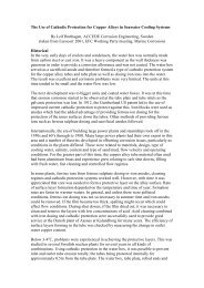
FIGURE P-2<br />
Cast sleeve bearings<br />
are available in a large<br />
variety of copper<br />
alloys.<br />
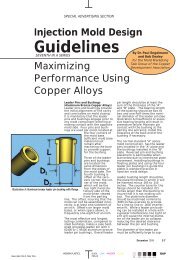
FIGURE P-1<br />
Cast aluminum bronze pickling hooks resist corrosion<br />
by hot, dilute sulfuric acid.<br />
FIGURE P-3<br />
A leaded semi-red brass<br />
was selected for this hot<br />
line clamp because it offers<br />
an economical combination<br />
of strength and corrosion<br />
resistance with adequate<br />
electrical conductivity.<br />
FIGURE P-4<br />
The aluminum bronze chosen for this complex motor<br />
segment casting enabled a 50% savings<br />
in machining costs compared with stainless steel.<br />
5
Understanding <strong>Copper</strong> Casting Alloys
I. CLASSIFYING THE <strong>COPPER</strong> <strong>ALLOYS</strong><br />
Over the years, copper alloys<br />
ha ve been identified by individual<br />
names and by a variety of numbering<br />
systems. Many of these names and<br />
numbers are still used. often interchangeably,<br />
and because this can be<br />
confusing. we will briefly explain how<br />
the various identification systems relate<br />
to each other. With this as a fo undation.<br />
we will next describe the families of<br />
copper al loys as they arc categorized in<br />
lOday' s nomenclature. In this chapter,<br />
we will also briefly discusses the various<br />
metals' metallurgical structures and<br />
foundry characteristics, since these are<br />
important considerat ions when deciding<br />
how a casting should be produced.<br />
Common Classification Systems<br />
A 1939 American Society for<br />
Testing and Materials (ASTM) standard,<br />
Classification of <strong>Copper</strong>-Base<br />
Alloys, codifi ed 23 distinct alloy families<br />
based on general compositional<br />
limits. Already-familiar designations<br />
such as "Leaded Brass," "Tin Bronze"<br />
and " Aluminum Bronze" were associated<br />
for the first time with specific composition<br />
ranges.<br />
Soon, other ASTM standards<br />
added designations for individual alloys<br />
within the families. For example,<br />
"Leaded Semi-Red Brass SA" was<br />
defined as an alloy containing between<br />
78% and 82% copper, 2.25% to 3.25%<br />
tin, 6% to 8% lead and 7% to 10% zinc,<br />
with stated limits on impurities.<br />
Minimum mechanical propelties were<br />
also fixed, permitting alloys to be<br />
called out in design specifications and<br />
construction codes.<br />
Another classification system still<br />
in use identifies alloys in terms of their<br />
nominal compositions. Thus, a leaded<br />
red brass containing 85% copper, 5% tin,<br />
5% lead and 5% zinc is simply called<br />
"85-5-5-5." while a leaded tin bronze is<br />
somewhat awkwardly designated as 88-<br />
6-l l h-4 I h. The system is limited to copper-tin-lead-zinc<br />
alloys (always given in<br />
that order). but there are some exceptions.<br />
Vatious other naming and/or numbering<br />
systems are used by. for example.<br />
ingot suppliers who fumi sh casting stock<br />
to foundries. or designers who. when<br />
they specify alloys, commonly call out<br />
ASTM or ASME standards or military<br />
specifications. None of these systems is<br />
obsolete; they are just not in general use<br />
in all industries.<br />
The UNS Numbering System<br />
In North America. the accepted<br />
designations for cast copper alloys are<br />
now part of the Unified Numbering<br />
System for Metals and Alloys (UNS),<br />
which is managed jointly by the ASTM<br />
and the Society of AUlOmotive Engineers<br />
(SAE). Under the UNS system, the copper<br />
alloys' identifiers take the form of<br />
five-digit ccx1es preceded by the letter "c."<br />
The five-digit codes are based on,<br />
and supersede, an older three-digit system<br />
developed by the U.s, copper and<br />
brass industry. The older system was<br />
administered by the <strong>Copper</strong><br />
<strong>Development</strong> <strong>Association</strong> (CDA), and<br />
alloys are still sometimes identified by<br />
their "CDA numbers." The UNS designations<br />
for copper alloys are si mply twodigit<br />
extensions of the CDA numbers.<br />
For example, the leaded red brass (85-5-<br />
5-5), once known as CDA <strong>Copper</strong> Alloy<br />
No. 836, became UNS C83600.<br />
This selection guide uses UNS<br />
numbers for all alloys, but traditional<br />
names are included for clarity wherever<br />
appropriate. In addition, alloys are<br />
described by their tempers, which are<br />
terms that defi ne metallurgical condilion.<br />
heat treatment. and/or casting<br />
method. The terminology assoc iated<br />
with tempers is spelled out in ASTM B<br />
60 1.7 and temper designations applicable<br />
to cast alloys are listed in Table 1,<br />
page S. For convenience. Table 2, page<br />
12, lists the alloys by UNS number,<br />
common name and conforming specifications.<br />
The UNS alloy list is updated<br />
periodicall y. New alloys may be added<br />
on request to COA, subject to a few<br />
simple restrictions, while alloys that are<br />
no longer produced are deleted. The<br />
alloys described in this handbook are<br />
listed in CDA's Standard Designations<br />
j(Jr Wrought alld Cast <strong>Copper</strong> al1d<br />
<strong>Copper</strong> Allol's, 1992 edition.<br />
The <strong>Copper</strong> Alloy Families:<br />
Classification and Major Uses<br />
Cast copper alloys are assigned<br />
UNS nu mbers from C80000 to C99999.<br />
The metals are arranged in a series of<br />
eight families drawn from the 18 compositionally<br />
related classifications previously<br />
identified by the ASTM. These<br />
families. some of which include subclassifications.<br />
include:<br />
<strong>Copper</strong>s (C80100-C81200).<br />
<strong>Copper</strong>s are high-purity metals with a<br />
minimum designated copper content of<br />
99.3%. They are not in tentionally<br />
alloyed but may contain traces of si lver<br />
or deoxidizers. The phosphorus deoxidizer<br />
in, for example, CS I200 renders<br />
this copper somewhat easier to weld by<br />
oxyacetylene techniques.<br />
The coppers are soft and ductile<br />
and are used almost exclusively for<br />
their unsurpassed electrical and thermal<br />
conducti vities in products such as terminals,<br />
connectors and (water-cooled) hot<br />
metal handling equipment. Figure 1-1,<br />
page 25 , shows a blast fumace tuyere<br />
7
TABLE 1. Standard Temper<br />
Designations for<br />
<strong>Copper</strong> Casting Alloys<br />
(Based on ASTM B 601)<br />
Temper Designations<br />
Annealed-O<br />
Temper Names<br />
010 Cast and Annealed<br />
(Homogenized)<br />
011 As Cast and Precipitation<br />
Heat Treated<br />
As-Manufaclured- M<br />
MOl<br />
M02<br />
M03<br />
MO'<br />
MOS<br />
M06<br />
MOl<br />
Heat-Treated-TO<br />
TOD~<br />
T030<br />
TOSO<br />
So lution Heal Treated<br />
and Spinodal Heat<br />
Treated-TX<br />
TXOO<br />
So lution Heal<br />
Treated-TB<br />
TBOO<br />
Solution Heat Treated<br />
and Precipitation Heal<br />
Treated-TF<br />
TfOO<br />
As Sand Cast<br />
As Centrifugal Cast<br />
As Plaster Cast<br />
As Pressure Die Cast<br />
As Permanent Mold Cast<br />
As Investment Cast<br />
As Continuous Cast<br />
Quench Hardened<br />
Quench Hardened and<br />
Tempered<br />
Quench Hardened and<br />
Temper Annealed<br />
Spinodal Hardened (AT)<br />
Solution Heat Treated (A)<br />
Precipitation Hardened (AT)<br />
cast from high conductivity copper. The<br />
coppers have very high corrosion resistance,<br />
but this is usually a secondary<br />
consideration.<br />
High <strong>Copper</strong> Alloys (C81400-<br />
C82800). Next in order of decreasing<br />
copper content are alloys with a minimum<br />
designated purity of 94% Cu. The<br />
high copper alloys are used primarily<br />
for their unique combination of high<br />
strength and good conductivity. Their<br />
corrosion resistance can be better than<br />
that of copper itself. Chromium coppers<br />
(C8 1400 and C81500), with a tensile<br />
strength of 45 ksi (3 10 MPa) and a conductivity<br />
of 82% lACS (see page 86)<br />
(as heat treated), are used in electrical<br />
contacts, clamps, welding gear and similar<br />
electromechanical hardware. At<br />
more than 160 ksi (1,100 MPa), the<br />
beryllium coppers have the highest ten·<br />
sile strengths of all the copper alloys.<br />
They are used in heavy duty mechanical<br />
and electromechanical equipment requiring<br />
ultrahigh strength and good electrical<br />
and/or thennal conductivity. The<br />
resistance welding machine component<br />
shown in Figure 1.2, page 25, was cast<br />
in beryllium copper for precisely those<br />
reasons.<br />
The high copper alloys' corrosion<br />
resistance is as good as or better than<br />
that of pure copper. It is adequate for<br />
electrical and electronic products used<br />
outdoors or in marine environments,<br />
which generally do not require extraordinary<br />
corrosion protection.<br />
Brasses (C83300-C87900).<br />
Brasses are copper alloys in which zinc<br />
is the principal alloying addition.<br />
Brasses may also contain specified<br />
quantities of lead, tin, manganese and<br />
silicon. There are five subcategories of<br />
cast brasses, including two groups of<br />
copper·tin-(lead)-zinc alloys:<br />
C833()()"c838I 0 and C842()()"c84800.<br />
the red and leaded red brasses and semired<br />
and leaded semi-red brasses, respectively;<br />
copper·zinc-(lead) alloys, C85200-<br />
C85800, yellow brasses and leaded<br />
yellow brasses;<br />
manganese bronzes and leaded manganese<br />
bronzes, C861 QO-{:86800,<br />
also known as high strength and leaded<br />
high strength yellow brasses; and,<br />
copper-silicon alloys, C87300-<br />
C87900, which are called silicon<br />
brasses or, if they contain more silicon<br />
than zinc, silicon bronzes.<br />
The lower the zinc content in the<br />
copper-tin-(lead)-zinc alloys. the more<br />
copper- like, or "red" they appear. With<br />
a few exceptions, red and leaded red<br />
brasses contain less than about 8% zinc;<br />
semi-red brasses, including the leaded<br />
versions, contain between 7% and 17%<br />
zinc, while yellow brasses and their<br />
leaded counterparts contain as much as<br />
4 1 % zinc. Brasses containing up to<br />
32.5% zinc are also sometimes called<br />
"alpha" brasses after the common designation<br />
for their single-phase, facecentered<br />
cubic crystal structure.<br />
Red and Semi-Red Brasses,<br />
Unleaded and Leaded (C83300-<br />
C84800). The most important brasses in<br />
tenns of tonnage poured are the leaded<br />
red brass, C83600 (85-5-5-5), and the<br />
leaded semi-red brasses, C84400,<br />
C84500 and C84800 (8 1-3-7-9, 78-3-7-<br />
12 and 76-3-6- 15, respecti vely). All of<br />
these alloys are widely used in water<br />
valves, pumps, pipe fittings and plumbing<br />
hardware. A typical downstream<br />
water meter is shown in Figure 1-3,<br />
page 25.<br />
Yellow Brasses (C85200-<br />
C85800). Leaded yellow brasses such<br />
as C85400 (67-1-3-29), C85700<br />
(63- 1- 1-35) and C85800 are relatively<br />
low in cost and have excellent castability,<br />
high machinabi lity and favorable<br />
finishing characteristics. Their corrosion<br />
resistance, while reasonably good, is<br />
lower than that of the red and semi-red<br />
brasses. Typical tensile strengths range<br />
from 34 to 55 ksi (234 to 379 MPa).<br />
Leaded yellow brasses are commonly<br />
used for mechanical products<br />
such as gears and machine components,<br />
in which relatively high strength and<br />
moderate con'osion resistance must be<br />
combined with superior machinability,<br />
The yellow brasses are often used for<br />
architectural trim and decorative hardware,<br />
The relatively narrow solidification<br />
range and good high-temperature<br />
ductility of the yellow brasses permi t<br />
some of these alloys to be die cast. The<br />
yellow brass door bolt shown in Figure<br />
1-4, page 52, was pressure die cast to<br />
near net shape, thereby avoiding the<br />
costly machining and fonning operations<br />
needed in an alternative manufacturing<br />
method. Other die-castable alloys include<br />
the structurally similar high strength<br />
yellow brasses and the silicon brasses.<br />
High Strength and Leaded High<br />
Strength Yellow Brasses (C86100-<br />
C86800), or manganese bronzes, are the<br />
strongest, as cast, of all the copper<br />
alloys. The "all beta" alloys C86200<br />
and C86300 (the alloys' structure is<br />
described below) develop typical tensile<br />
strengths of95 and 11 5 ksi (655 and<br />
793 MPa), respectively, without heat<br />
treatment. These alloys are weldable,<br />
but should be given a post-weld stress<br />
relief. The high strength brasses are<br />
8
used principally for heavy duty<br />
mechanical products requiring moderately<br />
good corrosion resistance at a reasonable<br />
cost. The rolling mill adjusting<br />
nut shown in Figure 1-5, page 52,<br />
provides a typical example. The high<br />
strength yellow brass alloys have been<br />
supplanted to some extent by aluminum<br />
bronzes, which offer comparable properties<br />
but have bener corrosion resistance<br />
and weldability.<br />
Silicon BronzeslBrasses<br />
(C87300-C87900) are moderate<br />
strength alloys with good corrosion<br />
resi stance and useful casting characteristics.<br />
Their solidification behavior<br />
makes alloys in this group amenable to<br />
die, pennanent mold and investment<br />
casting methods. Applications range<br />
from bearings and gears to plumbing<br />
goods and intricately shaped pump and<br />
valve components.<br />
Bronzes. The term "bronze" originally<br />
referred to alloys in which tin was<br />
the major alloying element. Under the<br />
UNS system, the teml now applies to a<br />
broader class of alloys in which the principal<br />
alloying element is neither zinc<br />
(which would form brasses) nor nickel<br />
(which forms copper-nickels).<br />
There are five subfamilies of<br />
bronzes among the cast copper aUoys:<br />
First listed are the copper-tin alloys,<br />
C902()()"'(:9 1 700, or tin bronzes. Next<br />
come the copper-tin-Iead alloys, which<br />
are further broken down into leaded tin<br />
bronzes, C922()()"'(:92900, and high<br />
leaded tin bronzes, C931 ()()"'(:94500.<br />
<strong>Copper</strong>-tin-nickel (lead) alloys include<br />
the nickel-tin bronze, C94700, and the<br />
leaded nickel-tin bronze, C94900. Both<br />
of these alloys contain less than 2% lead.<br />
Similar alloys with higher nickel contents,<br />
C973()()"'(:97800, are classified as<br />
copper-nickel-zinc alloys, but are more<br />
commonly known as nickel silvers or<br />
Gennan silvers. <strong>Copper</strong>-aluminum-iron<br />
and copper-aluminum-iron-nickel alloys,<br />
C952()()"'(:95900, are classified as aluminum<br />
bronzes and nickel-aluminum<br />
bronzes. Manganese bronzes are listed<br />
among the brasses because of their high<br />
zinc content.<br />
Tin bronzes offer excellent corrosion<br />
resistance, reasonably high strength<br />
and good wear resistance. Used in<br />
sleeve bearings, they wear especially<br />
well against steel. Unleaded tin bronze<br />
C90300 (88-8-0-4) is used for bearings,<br />
pump impellers, piston rings, valve fittings<br />
and other mechanical products.<br />
The alloy's leaded version, C92300 (87-<br />
8-1-4), has similar uses, but is specified<br />
when better machinability andlor pressure<br />
tightness is needed. Alloy C90500,<br />
formerly known as SAE Alloy 62, is hard<br />
and strong, and has especially good resistance<br />
to seawater corrosion. Used in bearings,<br />
it resists pounding well, but lacking<br />
lead, it requires reliable lubrication and<br />
shaft hardnesses of 300 to 400 HB.<br />
Alloy C93200 is the best-known<br />
bronze bearing alloy. Widely available<br />
and somewhat less expensive than<br />
other bearing alloys, this high leaded<br />
tin bronze is also known as «Bearing<br />
Bronze." The alloy is recognized for<br />
its unsurpassed wear performance<br />
against steel journals. It can be used<br />
against unhardened and not-perfectlysmooth<br />
shafts.<br />
Alloy C93500, another high leaded<br />
tin bronze, combines favorable<br />
anti friction properties with good loadcarrying<br />
capacities; it also confonns to<br />
slight shaft misalignments. Alloy<br />
C93600, a higher lead, lower zinc<br />
bronze bearing alloy is claimed to provide<br />
faster machining, lower friction<br />
and improved corrosion resistance in<br />
sulfite media. The higher tin content of<br />
alloy C93700 (formerly SAE 64) gives<br />
it resistance to corrosion in mild ac ids,<br />
mine waters and paper mill sulfite<br />
liquors.<br />
Lead weakens all of these bearing<br />
alloys but imparts the ability to tolerate<br />
intenupted lubrication. Lead also allows<br />
dirt particles to become embeded harmlessly<br />
in the bearing's surface, thereby<br />
protecting the journal. This is important<br />
in off-highway equipment such as<br />
the shovel loader shown in Figure 1-6,<br />
page 52. The "premier" bearing alloys,<br />
C93800 and C94300 also wear very<br />
well with steel and are best known for<br />
their ability to conform to slightly misaligned<br />
shafts.<br />
Nickel-Tin Bronzes (C94700-<br />
C94900). The nickel-tin bronzes are<br />
characterized by moderate strength and<br />
very good corrosion resistance, especially<br />
in aqueous media. One member of this<br />
family, C94700, can be age-hardened to<br />
typical tensile strengths as high as 75 ksi<br />
(517 MPa). Wear resistance is particularly<br />
good. Like the tin bronzes, nickel-tin<br />
bronzes are used for bearings, but these<br />
versatile alloys more frequentl y find<br />
application as valve and pump components,<br />
gears, shifter forks and circuit<br />
breaker parts.<br />
Nickel Silvers (C97300-<br />
C97800). These copper-nickel-tin-Ieadzinc<br />
alloys offer excellent corrosion<br />
resistance, high castability and very good<br />
machinability. They have moderate<br />
strength. Among their useful attributes is<br />
their pleasing silvery luster. Valves, fittings<br />
and hardware cast in nkkel silvers<br />
are used in food and beverage handling<br />
equipment and as seals and labyrinth<br />
rings in steam turbines.<br />
Aluminum Bronzes (C9S200-<br />
C95800). These alloys contain between<br />
3% and 12% aluminum. Aluminum<br />
strengthens copper and imparts oxidation<br />
resistance by forming a tenacious alumina-rich<br />
surface film. Iron, silicon, nickel<br />
and manganese are added to aluminum<br />
bronzes singly or in combination for<br />
higher strength andlor corrosion resistance<br />
in specific media.<br />
Aluminum bronzes are best<br />
known for their high corrosion and oxidation<br />
resistance combined with exceptionall<br />
y good mechanical properties. The<br />
alloys are readily fabricated and welded<br />
and have been used to produce some of<br />
the largest nonferrous cast structures in<br />
existence. Aluminum bronze bearings<br />
are used in heavily loaded applications.<br />
Alloy C95200, with about 9.5%<br />
aluminum, develops a tensile strength of<br />
80 ksi (550 MPa) as cast. Alloys C95400<br />
and C95500, which contain at least 10%<br />
aluminum, can be quenched and tempered<br />
much like steels to reach tensile<br />
strengths of 105 ksi (724 MPa) and 120<br />
ksi (827 MPa), respectively.<br />
Resistance to seawater corrosion is<br />
exceptionally high in nickel-aluminum<br />
bronzes. Because of its superior resistance<br />
to erosion-corrosion and cavitation,<br />
nickel-aluminum bronze<br />
C95500 is now widely used for propellers<br />
and other marine hardware,<br />
Figure 1-7, page 53.<br />
9
Another nickel-aluminum bronze,<br />
C958OO, is not heat treated, but nevertheless<br />
attains a typical strength of 95<br />
ksi (655 MPa). It should be temperannealed<br />
for service in seawater and<br />
other aggressive environments in order<br />
to reduce the likelihood of dealuminification<br />
corrosion (see page 54). The<br />
alloy's very good galling resistance,<br />
especially against ferrous metals, has<br />
increased its use for bearings and wear<br />
rings in hydroelectric turbines. Such<br />
bearings must be designed for adequate<br />
positive lubrication, andjournals must<br />
display a minimum hardness of 300 HB.<br />
<strong>Copper</strong>-Nickel Alloys (C96200-<br />
C96900). Sometimes referred to as copper-nickels<br />
or cupronickels, these comprise<br />
a set of solid-solution alloys<br />
contai ning between 10% and 30%<br />
nickel. The alloys also contain small<br />
amounts of iron and in some cases<br />
niobium (columbium) or beryllium for<br />
added strength. Seven standard alloys<br />
are currently recognized. Corrosion<br />
resistance and strength increase with<br />
nickel content, but it is the secondary<br />
alloying elements that have an overriding<br />
effect on mechanical properties.<br />
Alloy C962OO, wi th nominally<br />
10% nickel, attains a typical tensile<br />
strength of about 45 ksi (3 10 MPa) in<br />
the as-cast condi tion. The 30% nickel<br />
grade, C964OO, can be oil-quenched<br />
from 1,050-1,250 F (565-677 C) to<br />
increase its strength and hardness<br />
through the precipitation of a complex<br />
nickel-columbium-silicon intennetallic<br />
compound. Tensile strengths will typically<br />
reach 60 ksi (41 4 MPa). The 30%<br />
nickel, beryllium-containing grade,<br />
C966OO, can be age-hardened to a<br />
strength of 110 ksi (758 MPa).<br />
The copper-nickel alloys offer<br />
excellent resistance to seawater corrosion.<br />
This, combined with their high<br />
strength and good fabricability, has<br />
found them a wide variety of uses in<br />
marine equipment. Typical products<br />
include pump components, impellers,<br />
valves, tailshaft sleeves, centrifugally<br />
cast pipe, fittings and marine products<br />
such as the centrifugally cast valve<br />
body (A lloy C96400) shown in Figure<br />
1-8, page 53. The alloys are never leaded,<br />
and their machining characteristics<br />
resemble those of pure copper.<br />
Leaded <strong>Copper</strong>s (C9820a<br />
C98840). The lead in these alloys is<br />
dispersed as discrete globules surrounded<br />
by a matrix of pure copper or<br />
high-copper alloy. The conductivity of<br />
the matrix remains high, being reduced<br />
only by whatever other alloying elements<br />
may be present. Lead contents<br />
range from about 25% in alloy C98200<br />
to as high as 58% in alloy C98840.<br />
Between I % and 5% tin is added to<br />
alloys C98820 and C98840 for added<br />
strength and hardness. Similarly, alloys<br />
C98400 and C98600 contain up to<br />
1.5% silver, while C98800 may contain<br />
up to 5.5% silver, balanced against the<br />
lead content to adjust the alloy's hardness.<br />
The leaded coppers offer the high<br />
corrosion resistance of copper and high<br />
copper alloys, along with the favorable<br />
lubricity and low friction characteristics<br />
of high leaded bronzes.<br />
Metallurgy and Foundry<br />
Characteristics<br />
The copper alloy families are<br />
based on composition and metallurgical<br />
structure. These, in turn, influence<br />
or are influenced by the way the metals<br />
solidify. Solidification behavior is<br />
an important consideration, both in<br />
casting design and when selecting a<br />
casting process. The fo llowing descriptions<br />
of the alloys according to their<br />
structures and freezing behavior is intended<br />
as a brief introduction to a very<br />
complex subject. More detailed discussions<br />
are available from other sources. I<br />
<strong>Copper</strong>s. <strong>Copper</strong>s are metallurgically<br />
simple materials, containing a<br />
single face-centered cubic alpha phase.<br />
(S mall amounts of oxides may be present<br />
in deoxidized grades.) <strong>Copper</strong>s<br />
solidify at a fixed temperature, 1,98 1 F<br />
(1,083 C), but there is usually some<br />
undercooling. Freezing begins as a<br />
thin chill zone at the mold wall, then<br />
follows the freezing point isotherm<br />
inward until the entire body has solidified.<br />
Cast structures exhibit columnar<br />
grain structures oriented perpendicular<br />
to the solidification front. Centerline<br />
shrinkage cavities can fonn at isolated<br />
"hot spots" and inadequately fed<br />
regions of the casti ng; this must be<br />
taken into account when laying out the<br />
casting's design.<br />
High <strong>Copper</strong> Alloys. Like the<br />
coppers, the high copper alloys solidify<br />
by skin formation fo llowed by<br />
columnar grain growth. With a few<br />
exceptions, the high copper alloys typically<br />
have very narrow freezing<br />
ranges and also produce centerline<br />
shrinkage in regions that are improperly<br />
fed.<br />
The chromium and beryllium<br />
coppers develop maximum mechanical<br />
properties through age-hardening heat<br />
treatments consisting of a solutionannealing<br />
step fo llowed by quenching<br />
and reheating to an appropriate aging<br />
temperature. Conducti vity is highest in<br />
the aged (maximum strength) or slightly<br />
overaged (lower strength but higher<br />
ductility) conditions, i.e., when the<br />
hardening element has mostly precipitated<br />
and the remaining matri x consists<br />
of nearly pure copper.<br />
Red a nd Semi-Red Brasses.<br />
These alloys go through an extended<br />
solidification range characteri zed by<br />
the growth of tiny tree-like structures<br />
known as dendrites, Figure 1-9, page<br />
53. As the alloys solidi fy, countless<br />
dendrites form and grow more or less<br />
uniformly throughout the casting. This<br />
leads to a structure made up of small,<br />
equiaxed grai ns.<br />
The dendritic solidification<br />
process produces what can best be<br />
described as an extended mushy-liquid<br />
stage. The metal that freezes first may<br />
have a slightly different composition<br />
than metal that freezes later on, a phenomenon<br />
called microsegregation, or<br />
"coring." Coring can sometimes be<br />
detrimental to mechanical and/or<br />
corrosion properties. but the seriousness<br />
of the effect, if any, depends on the<br />
alloy and the particular environment.<br />
As the interlocking dendrites<br />
grow, they eventually shut off the supply<br />
of liquid metal. This produces tiny<br />
shrinkage voids, called microporosity,<br />
between the arms of the last dendrites to<br />
solidify. Microporosity can often be tolerated,<br />
but it is obviously detrimental<br />
when pressure tightness or high mechanical<br />
properties are needed. Porosity in<br />
10
these wide-freezing-range brasses can<br />
be avoided by controlling directional<br />
solidification, i.e., forcing the freezing<br />
front 10 follow a desired path. This<br />
ensures that even the last regions to<br />
solidify have access to an adequate supply<br />
of liquid metal. It should be noted<br />
that the red and semi-red brasses are the<br />
best alloys to specify for thin-walled<br />
sand castings and that leaded versions<br />
produce the best degrees of pressure<br />
tightness for reasonably th in sections.<br />
Yellow Brasses. These alloys<br />
also solidify by the fonnation of dendrites,<br />
however the te ndency to form<br />
microporosity and microsegregation is<br />
reduced because they tend to solidify<br />
over a relatively nmTOW temperature<br />
ra nge when chill-cast.<br />
The microstructu re of yellow<br />
brasses containing more than 32.5% zinc<br />
consists of a mixture of the solid-solution<br />
alpha phase 'Uld the hard. strong beta phase.<br />
In ye llow brasses, the amount of beta<br />
present depends on the alloys' zinc content;<br />
in high strength yellow brasses it depends<br />
on zinc and aluminum levels. In both<br />
cases, beta content is also influenced by<br />
the rate of cooling after solidification.<br />
Aluminum is such a strong beta former<br />
that alloy C86200, which contains only<br />
4% aluminum in addition to about 25%<br />
zi nc, has a predominantly beta<br />
microstructure. Formation of the beta<br />
phase leads to a significant increase in<br />
strength at low to moderate temperatures.<br />
Considering their moderately<br />
high strength, the yellow brasses are<br />
very ductile materials at low and intermediate<br />
temperatures. On the other<br />
hand, the most important metallurgical<br />
effect of the beta phase is that it raises<br />
ductility significantly at high temperatures.<br />
This improves the alloys' resistance<br />
to hot cracking in highly<br />
restrained molds, and allows some yellow<br />
brasses to be cast by the pressure<br />
die and/or permanent mold processes.<br />
Bronzes. Tin increases strength<br />
and improves aqueous corrosion resistance.<br />
It also increases cost, therefore<br />
alloy selection involving tin bronzes<br />
may entail a cost-benefits analysis. Tin<br />
dramatically expands the freezi ng range<br />
in copper alloys and usually produces<br />
significant coring, although this is not<br />
necessari ly harmful.<br />
Leaded <strong>Copper</strong>s. These alloys<br />
undergo a two-step solidification<br />
process. That is, the copper frac tion<br />
(pure copper or high-copper alloy)<br />
freezes over the narrow solidification<br />
range typical of such alloys. The lead<br />
solidifies only after the casting has<br />
cooled some 1,300 Fahrenheit (700<br />
Celsius) degrees. Segregation of lead to<br />
the last regions to solidify is therefore a<br />
potentially serious problem. Chill-casting<br />
and/or using thin sections help trap<br />
the lead in a uniform dispersion<br />
throughout the structure.<br />
Nickel-Tin Bronzes. The nickeltin<br />
bronzes can be heat treated to produce<br />
precipitation hardening. The<br />
precipitat ing phase is a copper-tin intermetall<br />
ic compound which fonns du rin g<br />
slow cooling in the mold or during a<br />
subsequent aging treatment. Lead is<br />
detrimental to the hardening process to<br />
the extent that leaded nickel-tin bronzes<br />
are not considered heat-treatable.<br />
Nickel Silvers. Despite their<br />
complex composition, nickel sil vers<br />
display simple alpha microstructures.<br />
Nickel, tin and zinc impmt solid solution<br />
hardening, and mechanical properties<br />
generally improve in proportion to<br />
the concentration of these elements. The<br />
nickel silvers are not heat treatable. The<br />
alloys' characteristic silver color is produced<br />
primarily by nickel. aided to<br />
some extent by zinc.<br />
Aluminum Bronzes. These<br />
alloys exhi bit some of the most interesting<br />
metallurgical structures found<br />
among all commercial alloys.<br />
Aluminum bronzes contai ning less than<br />
about 9.25% aluminum consist mainly<br />
of the face-centered cubic alpha structure,<br />
although iron- and nickel-rich<br />
phases. which contribute strength, will<br />
also be present. Higher aluminum<br />
concentrations, and/or the addi tion of<br />
silicon or manganese, lead to the formation<br />
of the beta phase. Beta transfoffi1s<br />
into a variety of secondary phases as the<br />
casting cools. Standard alloy compositions<br />
are carefull y balanced to ensure<br />
that the resulting complex structures m'e<br />
beneficial to the bronzes' mechanical<br />
properties.<br />
Despite their metallurgical complexity,<br />
the al uminum bronzes are extraordinarily<br />
versatile alloys. They are well<br />
suited to sand casting and are often produced<br />
by this method. They are also fre·<br />
quently cast centrifugally. On the other<br />
hand, the aluminum bronzes are basically<br />
short-freezing alloys and this. coupled<br />
with their good elevated temperature<br />
properties, also makes them good candidates<br />
for the permanent mold and die<br />
casting processes.<br />
<strong>Copper</strong>-Nickels. The coppernickels<br />
are metallurgically simple alloys,<br />
consisting of a continuous series of solid<br />
solutions throughout the copper-nickel<br />
system. <strong>Copper</strong>-rich alloys in the copper-nickel<br />
system are known as coppernickels;<br />
nickel-rich compositions in this<br />
system are called Monel alloys. The<br />
copper-nickels solidify over narrow<br />
freezi ng ranges, although the range<br />
extends somewhat wi th increasing nickel<br />
content. Segregation is not a serious<br />
problem.<br />
Iron, niobium (columbium) and<br />
sil icon can produce precipitation hardening<br />
in copper-nickels through the formation<br />
of silicides; however,<br />
precipitation takes place readily as the<br />
casting cools, and the alloys are consequently<br />
not age-hardenable. On the<br />
other hand. beryllium-containing<br />
C96600 can be age-hardened in the<br />
same manner as can ordinary berylliumcopper<br />
alloys.<br />
Effects of Lead<br />
As leaded copper alloys freeze, the<br />
lead segregates as microscopic liquid<br />
pools which fill and seal the interdendritic<br />
microporosity left when the highermelting<br />
constituents solidified, Figure<br />
1-10, page 53 . The lead seals the pores<br />
and renders the casting pressure-tight.<br />
Lead also makes the alloys free-cutting<br />
by promoting the fOffi1ation of small,<br />
easily cleared turnings during machining.<br />
This improves high-speed finis hi ng operations.<br />
Unless present in high concentrations.<br />
lead does not have a strong effect<br />
on strength, but it does degrade ductility.<br />
<strong>Copper</strong> alloys containing lead cannot be<br />
welded, although they can be brazed<br />
and soldered.<br />
11
TABLE 2. Overview of <strong>Copper</strong> Casting Alloys<br />
UNS<br />
Number<br />
Other Designations ,<br />
Descriptive Names<br />
(Former SAE No.)<br />
Applicable<br />
Casting<br />
Processes<br />
(See legend)<br />
Cu<br />
Composition, percent ma ximum, unless shown as a range or minimum· ----<br />
Sn<br />
Pb<br />
Zn<br />
Ni Fe<br />
Other<br />
Uses, Significant<br />
Characteristics<br />
<strong>Copper</strong>s<br />
C80100(1,2)<br />
C811 00(1.2)<br />
Oxygen-Free <strong>Copper</strong><br />
High Conductivity <strong>Copper</strong><br />
S, C, el.<br />
PM, I, P<br />
S, C, CL,<br />
PM, I, P<br />
99.95 (3 ) -<br />
99.70(3) -<br />
- -<br />
- -<br />
-<br />
-<br />
-<br />
-<br />
-<br />
-<br />
High purity coppers with<br />
excellent electrical and<br />
thermal conductivities.<br />
Deoxidation of C81200<br />
improves its weldability.<br />
C812DD(I)<br />
High Conductivity <strong>Copper</strong><br />
S, C, el.<br />
PM, I, P<br />
99.9 (3 ) -<br />
- -<br />
-<br />
-<br />
.045-.065 P<br />
High <strong>Copper</strong> Alloys<br />
C8140D(I.2) lOC S, C, el.<br />
PM, I, P<br />
C81 50011 .2) Chromium <strong>Copper</strong><br />
S, C, Cl,<br />
PM, I, P<br />
C81540P) Chromium <strong>Copper</strong> S, C. Cl,<br />
PM, I, P<br />
C820001 1.2) 10C S, C, Cl,<br />
PM, I, P,<br />
0<br />
C822001U) 35C,53B<br />
C8240011 .2) 165C<br />
S, C, Cl,<br />
PM, I, P<br />
S, C, Cl,<br />
PM, I. p.<br />
0<br />
98.5 min.I.) -<br />
98.0 min.!') .10<br />
95.1 min.I4.5) 10<br />
Rem.I') .10<br />
Rem.!4) -<br />
Rem ,I') .10<br />
- -<br />
.02 .10<br />
02 10<br />
.02 10<br />
- -<br />
.02 .10<br />
-<br />
-<br />
2.0- 3.0 (6 )<br />
20<br />
1.0--2.0<br />
.20<br />
-<br />
-<br />
.02-.10 Be<br />
.6-1.0Cr<br />
.10 .15 Si<br />
.10AI<br />
. 4D-l.5 Cr<br />
.15 .40-.8 Si<br />
.10AI<br />
.1D-.6 Cr<br />
.10 .10AI<br />
.1 0 Cr<br />
.15 Si<br />
2.4D-2.70 COI6)<br />
.45- .8 Be<br />
.35-.80 Be<br />
.30 Co<br />
.20 .20-.65 Co<br />
1.60--1.85 Be<br />
.15 AI<br />
.10 Cr<br />
Relatively high strength<br />
coppers with good electrical<br />
and thermal conductivity.<br />
Strength generally<br />
inversely proportional<br />
to conductivities .<br />
Used where good combination<br />
of strength and<br />
conductivity is needed ,<br />
as in resistance welding<br />
electrodes, switch blades<br />
and components, dies,<br />
clutch rings, brake<br />
drums, as well as bearings<br />
and bushings. Beryllium<br />
coppers have<br />
highest strength of all<br />
copper alloys, are used<br />
in bearings, mechanical<br />
products and non-sparking<br />
safety tools.<br />
C82500(1·2) 20C S, C, CL,<br />
PM , I, P,<br />
0<br />
Rem.(4) .10<br />
.02 .10<br />
.20<br />
.25 1.90--2.25 Be<br />
,35-.70 CoIS)<br />
.20--.35 Si<br />
.15 AI<br />
.10 Cr<br />
C8251D Increased-Co 20C S, C. CL,<br />
PM , I, p.<br />
0<br />
Rem.14) .10<br />
.02 .10<br />
.20<br />
.25 1.90--2,15 Be<br />
1.0--1.2 COI6)<br />
.20--.35 Si<br />
15 AI<br />
.10 Cr<br />
C8260Dll.2) 245C S, C. CL,<br />
PM , I, P,<br />
0<br />
Rem,14) .10<br />
.02 .10<br />
.20<br />
.25 2.25-2.55 Be<br />
.35-.65 Co<br />
.20--.35 Si<br />
.15 AI<br />
.10 Cr<br />
C8270D I1.2) Nickel-Beryllium <strong>Copper</strong> S, C, CL,<br />
PM, I, P<br />
Rem.14) .1 0<br />
.02 .10<br />
1.0-1.5<br />
.25 2.35-2.55 Be<br />
.15 Si<br />
.15 AI<br />
.10 Cr<br />
\continued on next page<br />
" Compositions are subject to minor changes. Consult latest edition 01 COA's<br />
Standard Designations for Wrought and Cast <strong>Copper</strong> and <strong>Copper</strong> Alloys.<br />
Rem. '" Remainder<br />
Legend' Applicable Casting Processes<br />
S '" Sand C '" Continuous Cl", Centrifugal<br />
0", Die I '" Investment P '" Plaster<br />
PM", Permanent Mold<br />
12
TABLE 2. Overview of <strong>Copper</strong> Casting Alloys I continued<br />
UNS<br />
Number<br />
other Designations ,<br />
Descriptive Names<br />
(Former SAE No.)<br />
Appllcable<br />
Casting<br />
Processes<br />
(See legend)<br />
Cu<br />
Composition , percent maximum , unless shown as a range or minimum· ----<br />
Sn<br />
Pb<br />
Zn<br />
Ifi Fe Other<br />
Uses, Significant<br />
Characteristics<br />
High <strong>Copper</strong> Alloys \continued<br />
C82800 11. 2 )<br />
27SC S, C, CL, Rem.(4)<br />
PM, I, P,<br />
0<br />
.10 .02<br />
.10<br />
.20<br />
.25 2.50-2.85 Be<br />
.35-.70 Co (6 )<br />
.20-.355i<br />
.15 AI<br />
.10 Cr<br />
<strong>Copper</strong>-Tin-Zinc and <strong>Copper</strong>-Tin-Zinc-Lead Alloys<br />
(Red and Leaded Red Brasses)<br />
C83300 11.2) 131, Contact Metal S, C, CL 92.0-94.0(1.8( 1.D-2.0<br />
C8340Qll.2) 407.5, Commercial Bronze S, C, CL 88.0-92.0 11 .11 20<br />
90/10, Gilding Metal<br />
1.0-2.0<br />
.50<br />
2.0-6.0<br />
8.0-12.0<br />
-<br />
1.0<br />
-<br />
.25 .25 Sb<br />
.08 S<br />
.03 P<br />
.005 Si<br />
. 005 AI<br />
-<br />
High-copper brasses<br />
with reasonable eleclrical<br />
conductivity and<br />
moderate strength. Used<br />
for electrical hardware,<br />
including cable cannectors<br />
.<br />
C8345D Nickel-Beari ng Leaded S, C, CL 87.D-89.017.8) 2.0-3.5<br />
Red Brass<br />
1.5-3.0<br />
5.5-7.5<br />
.8- 2.0 (9 )<br />
.30 .25 Sb<br />
,08 S<br />
.03 p(10)<br />
.005 AI<br />
.005 Si<br />
C83S00 leaded Nickel-Bearing Tin S, C, Cl 86.0-88.017,8) 5.5-6.5<br />
Bronze<br />
3.5- 5.5<br />
1.0-2.5<br />
.50-1.0 (9 )<br />
.25 .25 Sb<br />
.08 S<br />
.03 p(10)<br />
.005 AI<br />
.005 Si<br />
C83600 11.2) 115, 85-5-5-5. S, C, Cl, 84.0-86.011,8) 4.0-6.0<br />
Composition Bronze,<br />
I<br />
Ounce Metal, (SAE 40)<br />
C83800It.2) 120, 83-4-6-7, S, C, Cl 82.0-83.8 17 ,1) 3.3-4.2<br />
Commercial Red Brass,<br />
HydrauliC Bronze<br />
C838l0 Nickel-Bearing Leaded Red S, C, CL Rem.IUI 2.0-3.5<br />
Brass<br />
4.0-6.0<br />
5.0-7.0<br />
4.0-6.0<br />
4.0-6.0<br />
5.0-8.0<br />
7.5-9.5<br />
1.0 (9 )<br />
1.0 191<br />
2.0 (9 )<br />
.30 .25 Sb<br />
.08 S<br />
.05 p11 0)<br />
.005 AI<br />
.005 Si<br />
.30 .25 Sb<br />
.08 S<br />
.03 pl1 0 1<br />
.005AI<br />
.005 Si<br />
.50(11) Sb lll )<br />
As(11)<br />
.005 AI<br />
. 10 Si<br />
Good corrosion resistance,<br />
excellent<br />
castability and moderate<br />
strength. Lead content<br />
ensures pressure tightness.<br />
Alloy C83600 is<br />
one of the most important<br />
casl alloys, widely<br />
used for plumbing filtings,<br />
other waler-service<br />
goods. Alloy<br />
C838DD has slighlly<br />
lower strength, but is<br />
essentially similar in<br />
properties and application<br />
.<br />
• Compositions are subject to minor changes. Consult latest edition of COA's<br />
Standard DeSignations lor Wrought and Cast <strong>Copper</strong> and <strong>Copper</strong> Alloys.<br />
Rem. = Remainder<br />
Legend ' Applicable Casting Processes<br />
S;; Sand C;; Continuous CL;; Centrifugal<br />
0= Die I;; Investmenl P = Plaster<br />
PM;; Permanent Mold<br />
13
TABLE 2. Overview of <strong>Copper</strong> Casting Alloys I continued<br />
UNS<br />
Number<br />
Applicable<br />
Other Designalions , Casting Composition , percent maximum , unless shown as a range or minimum *<br />
Descriptive Nam es Processes<br />
Uses , Significant<br />
(Former SAE No .) (See legend) Cu Sn<br />
Pb<br />
Zn Ni F. Other Ch aracteristics<br />
<strong>Copper</strong>-Tin-Zinc-Lead Alloys<br />
(Leaded Semi-Red Brasses)<br />
C84200(1·2)<br />
C84400P.2)<br />
101,80-5-2 1 /2-12'/2 S, C. CL 78.0--82.017.BI 4.0-6.0<br />
123,81-3-7-9, S, C, CL 78.0-82.017.BI 2.3-3.5<br />
Valve Composition ,<br />
81 Metal<br />
2.0-3.0<br />
6.0-8.0<br />
10.0--16.0 a19) .40 .25 Sb General purpose alloys<br />
.08 S for plumbing and hard-<br />
.05 pllQ) ware goods. Good rna-<br />
.005 AI chinabil ity, pressure<br />
.005 Si tightness . Alloy C84400<br />
is the most popular<br />
7.0-10.0 1.0 19) 40 .25 Sb plumb ing alloy in U.S.<br />
. 08 S markets .<br />
.02 pPO)<br />
.005 AI<br />
.005 Si<br />
C8 4410<br />
S, C. Cl Rem. 17. 8 ) 3.0-4.5<br />
7.0- 9.0<br />
7.0-1 1.0 1.019) 113) Sb l1J1<br />
.01 AI<br />
.20 Si<br />
.05 Bi<br />
C845001 1.2)<br />
125. 78 Metal S, C. CL 77.0-79.017. 8 ) 2.0-4.0<br />
6.0-7.5<br />
10.0-14.0 1.019) .40 .25 Sb<br />
.08 S<br />
.02 p(10)<br />
.005 AI<br />
.005 Si<br />
C84800iU )<br />
130,76-3-6-15, 76 Metal S, C, CL 75.0-77.0 17. 8 ) 2.0-3.0<br />
5.5-7.0<br />
13.0-17.0 10191 .40 .25 Sb<br />
.08 S<br />
.02 plIO)<br />
.005 AI<br />
.005 Si<br />
<strong>Copper</strong>-Zinc and <strong>Copper</strong>-Zinc-Lead Alloys<br />
(Yellow and Leaded Yellow Brasses)<br />
C85200 (1)<br />
C85400 1.21<br />
C85500 11.2)<br />
C85700 11.2)<br />
400, 72-1-3-24, S, C, Cl 70.0-74.0(7,14) 7-2.0<br />
High Coppe r Yellow Brass,<br />
403.67-1-3-29, S, C, CL, 65.0-70.017. 19 ) .50-1.5<br />
Commrcl. NO.1 Yellow Brass PM, I, P<br />
60-40 Ye llow Brass S, C, CL 59.0---63.017.191 .20<br />
405.2,63-1-1-35, 82, S, C, CL, 58.0-64.011. 141 .50-1.5<br />
Permanent Mold Brass PM , I. P<br />
1.5-3.8<br />
1.5-3.8<br />
.20<br />
.80-1.5<br />
20.0-27 .0 1.0 (9 ) .6 20 Sb Low-cost, low-to-moder-<br />
.05 S ate strength , general-<br />
02P purpose casting al loys<br />
.005 AI with good machinability,<br />
.05 Si adequate corrosion resistance<br />
for many wate r-<br />
24.0- 32.0 1.019) .7 35 AI service applications in-<br />
05 Si cluding marine hardware<br />
and automotive cooling<br />
Rem. .20191 .20 .20 Mn systems. Some compositions<br />
are amenable to<br />
32.0-40.0 1.0 (9 ) 7 .8 AI permanent mold and die<br />
.05 Si casting processes.<br />
C8580011.2)<br />
405.1, Die Casting Yellow S, C, CL, 57.0 min.!1,19) 1.5<br />
Brass<br />
PM , I, P<br />
0<br />
1.5<br />
31.0-41.0 .50 191 .50 05 Sb<br />
.25 Mn<br />
.05 As<br />
.05 S<br />
.01 P<br />
.55 AI<br />
.25 Si<br />
• Compositions are subject to minor changes. Consulliatest edition of COA's<br />
Standard Designations for Wrought and Cast <strong>Copper</strong> and <strong>Copper</strong> Alloys.<br />
Rem. = Remainder<br />
legend: Aoolicable Casting processes<br />
S = Sand C = Continuous Cl = Centrifugal<br />
o = Die I = Investment P = Plaster<br />
PM = Permanent Mold<br />
14
TABLE 2. Overview of <strong>Copper</strong> Casting Alloys Icontinued<br />
Applicab le<br />
Other Designations , Casting<br />
Composition , percent maximum, un less shown as a range or minimum· ----<br />
UNS Oescriptive Nam es Processes<br />
Num ber (Former SAE No.) (See legend) Cu Sn Pb Zn<br />
Ni<br />
Fe other<br />
Uses , Significant<br />
Characteristics<br />
Manganese Bronze and Leaded Manganese Bronze Alloys<br />
(High Strength and Leaded High Strength Yellow Brasses)<br />
CB6100 (1·2) 423, 90,000 Tensile S, CL, PM , 66.D-68.0(7,IS) . 20<br />
Manganese Bronze<br />
I, P<br />
C86200(1) 423,95,000 Tensile S, C, CL, 60.0-66.0(1·15) .20<br />
Manganese Bronze, PM, I, P,<br />
(SAE 430A) 0<br />
CB6300(1) 424,110,000 Tensile S, C, CL, 60.0-66.017,15) .20<br />
Manganese Bronze, PM, I, P<br />
(SAE 430B)<br />
CB6400(1,Z) 420, 60,000 Tensile S, C, CL, 56.0-62 .0(7,15) .50-1.5<br />
Manganese Bronze PM , I, P,<br />
0<br />
C8650011,Zl 421, 65,000 Tensile S. C, CL. 55.0-60.015. 13 ) 1.0<br />
Manganese Bronze.<br />
PM , I, P<br />
(SAE 43)<br />
.20 Rem .<br />
.20 22.0-28.0<br />
.20 22.0-2B.0<br />
.50-1.5 34.0-42.0<br />
.40 36.0-42.0<br />
-<br />
1.0 (9 )<br />
1.0(9)<br />
1.0 (9 )<br />
1.0(9)<br />
2.0-4.0 4.5-5.5 AI<br />
2.5-5.5 Mn<br />
2.0-4.0 3.0-4.9 AI<br />
2.5-5.0 Mn<br />
2.0-4 .0 5.0-7.5 AI<br />
2,5-5,0 Mn<br />
.40-2.0 .50-1.5 AI<br />
.10-1 .5 Mn<br />
.40-2.0 .50-1.5 AI<br />
.10-1.5 Mn<br />
Alloys with high mechanical<br />
strength , good<br />
corrosion resistance and<br />
favorable castability. Can<br />
be machined , but with<br />
the exception of C86400<br />
and C86700, are less<br />
readily machined than<br />
leaded compositions.<br />
Alloy C86300 can altain<br />
tensile strengths exceeding<br />
115 ksi (793 MPa).<br />
Used for mechanical devices:<br />
gears, levers,<br />
brackets, valve and<br />
pump components for<br />
fresh and seawater service.<br />
When used for<br />
high strength bearings,<br />
alloys C86300 and<br />
C86400 require hardened<br />
shafts.<br />
CB670011.Z) 422 , BO.OOO Tensile S, C. CL, 55.0-60.017.15) 1.5<br />
Manganese Bronze<br />
PM, I, P<br />
.50-1.5 30.0-38.0<br />
1.0 (9 )<br />
1.0-3.0 1.0-3.0 AI<br />
.10-3.5 Mn<br />
CB6BOO (1.Z) Nickel-Manganese Bronze S, C, CL, 53.5-57.017,15) 1.0<br />
PM, I. P<br />
. 20 Rem .<br />
2.5-4 .019)<br />
1.0-2.5 2,0 AI<br />
2.5-4.0 Mn<br />
<strong>Copper</strong>-Silicon Alloys<br />
(Silicon Bronzes and Silicon Brasses)<br />
CB7300 95-1-4, Silicon Bronze S, C, CL, 94.0 min.I() -<br />
PM , I, P<br />
CB7400(1,Z) 500 S, CL, PM, 79.0 min.I() -<br />
I, P, D<br />
CB750011,2) 500 S, CL, PM, 79.0 min.I() -<br />
I, P, D<br />
CB7600 11.2) 500, Low Zinc Silicon 8rass S, CL, PM, 88.0 min.l 4 ) -<br />
I, P, D<br />
C87610 S, CL, PM, 90.0 min.(4) -<br />
I, P, 0<br />
.20 .25<br />
1.0 12.0-16.0<br />
.50 12.0-16.0<br />
.50 4.0-7.0<br />
.20 3.0--5.0<br />
-<br />
-<br />
-<br />
-<br />
-<br />
.20 3.5-4.5 Si<br />
.SO-I.5 Mn<br />
- .BO AI<br />
2.5-4.0 Si<br />
- .50AI<br />
3.0-5.0 Si<br />
.20 3.5-5.5 Si<br />
.25 Mn<br />
.20 3.0-5.0 Si<br />
.25 Mn<br />
Moderate-to-high<br />
strength alloys with<br />
good corrosion resistance<br />
and favorable castjng<br />
properties. Used for<br />
mechanical products and<br />
pump components<br />
where combination of<br />
strength and corrosion<br />
resistance is important.<br />
Similar compositions are<br />
commonly die and/or<br />
permanent mold cast in<br />
Europe and the U.K.<br />
C87800(1,2) 500, Die Cast Silicon Brass S, CL, PM , 80.0 min.l 4 ) .25<br />
I, P: 0<br />
.15 12.0--16.0<br />
.20(9)<br />
.15 .15 AI<br />
3.8-4.2 Si<br />
.15 Mn<br />
.01 Mg<br />
.05 S<br />
.01 P<br />
.05 As<br />
.05 Sb<br />
" Composilions are subject to minor changes, Consult latest edition of COA's<br />
Standard Designations for Wrought and Cast <strong>Copper</strong> and <strong>Copper</strong> Alloys.<br />
Rem. = Remainder<br />
Legend ' Applica ble Casting Proc esses<br />
S = Sand C = Continuous CL = Centrifugal<br />
o = Die I = Investmenl P = Plaster<br />
PM = Permanent Mold<br />
15
TABLE 2. Overview of <strong>Copper</strong> Casting Alloys \continued<br />
UNS<br />
Number<br />
other Designations ,<br />
Descriptive Nam es<br />
(Former SAE No.)<br />
Applicable<br />
Casting<br />
Processes<br />
(See legend)<br />
Cu<br />
Composition , percent maximum , unless shown as a range Dr minimum'" ----<br />
Sn<br />
Pb<br />
Zn<br />
Ni<br />
Fe OIher<br />
Uses, Significant<br />
Characteristics<br />
<strong>Copper</strong>-Tin Alloys<br />
(Tin Bronzes)<br />
C90200 11. 2 )<br />
C9030Qll.2)<br />
C90500 11.21<br />
242, 93-7-0-0, S, C, CL.<br />
PM , I, P<br />
225, 88-8-0-4, S, C, CL,<br />
Navy "G" Bronze,<br />
PM , I, P<br />
(SAE 620)<br />
210, 88-10-0-2 , S, C, CL,<br />
Gun Metal, (SAE 62) PM, I, P<br />
91 .0-94.01 7.16) 6.0-8.0<br />
86.0-89.0 17. 16 ) 7.5-9.0<br />
86.0-89.0(1.251 9.0-11.0<br />
.30<br />
.30<br />
.30<br />
.50 .50(9)<br />
3.0-5.0 1.0(9)<br />
1.0-3.0 1.0(91<br />
.20 .20 Sb<br />
.05 S<br />
.05 pll0j<br />
.DOSAI<br />
.005 Si<br />
.20 . 20 Sb<br />
.05 S<br />
.05 p(101<br />
.005 AI<br />
.005 SI<br />
.20 .20 Sb<br />
.05 S<br />
.05 p( lOI<br />
.005 AI<br />
.005 Si<br />
Hard, strong alloys with<br />
good corrosion resislance,<br />
especially against<br />
seawater. As bearings,<br />
they are wear resistant<br />
and resist pounding well.<br />
Moderately machinable .<br />
Widely used for gears,<br />
worm wheels, bearings,<br />
marine fittings, piston<br />
rings, and pump components.<br />
C90700(1.21<br />
205 , 89-11 , (SAE 65) S, C, CL,<br />
PM, I, P<br />
88.0-90.0(1·161 10.0-12.0<br />
.50<br />
.50 .50(91<br />
.15 .20 Sb<br />
.05 S<br />
.30 p( lO I<br />
.005 AI<br />
.005 Si<br />
C90710<br />
S, C, CL.<br />
PM, I, P<br />
Remp· 161 10.0-12.0<br />
.25<br />
.05 .10(91<br />
.10 .20 Sb<br />
.05 S<br />
.05-1.2 pl 101<br />
.005 AI<br />
.005 Si<br />
C9080D<br />
S, C, CL,<br />
PM , I, P<br />
85.0-89.017.161 11 .0-13.0<br />
.25<br />
.25 .50(91<br />
.15 .20 Sb<br />
.05 S<br />
.30 p(lOI<br />
.005 AI<br />
.005 Si<br />
C90810<br />
S, C, CL,<br />
PM, I, P<br />
Rem.(1. 161 11.0-13.0<br />
.25<br />
.30 .50 191<br />
.15 .20 Sb<br />
.05 S<br />
.15-.8 p(l OI<br />
.005 AI<br />
.005 SI<br />
C90900(1.21<br />
199, 87-13-0-0 S, C, CL,<br />
PM, I, P<br />
86.0-89.0(7. 161 12.0-14.0<br />
.25<br />
.25 .50(91<br />
.15 .20 Sb<br />
.05 S<br />
.05 p( l OI<br />
.005 AI<br />
.005 Si<br />
C91000(1.21<br />
197,85-14-0-1 S, C, CL,<br />
PM, I, P<br />
84.0-86.0(7.161 14.0-16.0<br />
.20<br />
1.5 .80(91<br />
.10 .20 Sb<br />
.05 S<br />
.05 p( lOI<br />
.005 AI<br />
.005 Si<br />
C91100(1 ·21<br />
\continued on next page<br />
84-16-0-0 S, C, CL,<br />
PM, I, P<br />
82.0-85.0(7. 16 f 15.0-17.0<br />
.25<br />
.25 .50(91<br />
.25 .20 Sb<br />
.05 S<br />
1.0 p(lO f<br />
.005 AI<br />
.005 Si<br />
* CompOSitions are subject 10 minor changes. Consult latest edition 01 COA's<br />
Standard Designations lor Wrought and Cast <strong>Copper</strong> and <strong>Copper</strong> Alloys.<br />
Rem. '" Remainder<br />
Legend: Aooljcable Casting Processes<br />
S", Sand C '" Conlinuous CL", Centrifugal<br />
o '" Die I '" Investmenl P", Plaster<br />
PM", Permanent Mold<br />
16
TABLE 2. Overview of <strong>Copper</strong> Casting Alloys I continued<br />
UNS<br />
Number<br />
Other De signations,<br />
De scriptive Nam es<br />
(Former SAE No.)<br />
Applicable<br />
Casting<br />
Processes<br />
(See Legend)<br />
Cu<br />
Composition, percent max imum, unless shown as a range or minimum '" ----<br />
Sn<br />
Pb<br />
Zn<br />
Ni<br />
Fe Other<br />
Uses, Significant<br />
Characteristics<br />
<strong>Copper</strong>-Tin Alloys Icontinued<br />
(Tin Bronzes)<br />
C91 300(1 .2)<br />
194, 81-19 S, C, CL,<br />
PM, I, P<br />
79.0-82.0(1.16)<br />
18.0- 20.0<br />
.25<br />
25 .50(9)<br />
.25 .20 Sb<br />
.05 S<br />
1.0 p(101<br />
.005 AI<br />
.005 Si<br />
C91600(1.2)<br />
205N. 88-10'/2-0-0-1' /2. S, C, CL,<br />
Nickel Gear Bronze<br />
PM, I, P<br />
86.0-89.0(1.15)<br />
9.7-10.8<br />
.25<br />
.25 1.2-2.0(9)<br />
20 .20 Sb<br />
.05 S<br />
.30 pliO)<br />
.005 AI<br />
.005 Si<br />
C91 700(1.2)<br />
86' /2-12-0-0-1' /2, S, C, CL,<br />
Nickel Gear Bronze PM,I , P<br />
84.Q-87.0(7.1&)<br />
11.3-12.5<br />
.25<br />
.25 1.20-2.0(9)<br />
.20 .20 Sb<br />
.05 S<br />
.30 pliO)<br />
.005 AI<br />
.005 Si<br />
<strong>Copper</strong>-Tin-Lead Alloys<br />
(Leaded Tin Bronzes)<br />
C922DOll.2)<br />
C92210<br />
245, 88-6-1 1 /2"4 1 /2, S, C, CL.<br />
Navy "M" Bronze.<br />
PM, I, P<br />
Steam Bronze, (SAE 622)<br />
-<br />
86.0-90.017·B1<br />
86.0-89.0(7.81<br />
5.5-6.5<br />
4.5-5.5<br />
1.0-2.0<br />
1.7-2.5<br />
3.0-5.0 1.0(9)<br />
3.0-4 .5 .7-1.0<br />
.25 .25 Sb<br />
.05 S<br />
.05 p(l D)<br />
.005 AI<br />
.005 Si<br />
.25 .25 Sb<br />
.05 S<br />
.03 P<br />
. 005 AI<br />
.005 Si<br />
Lead improves machinability<br />
in these tin<br />
bronzes but does not<br />
materially affect mechanical<br />
properties. The<br />
alloys are essentially<br />
free-cutting versions of<br />
the tin bronzes , above,<br />
and have simi lar properties<br />
and uses .<br />
C92300 (1.2)<br />
230,87-8-1-4 S, C, CL,<br />
Leaded "G" Bronze<br />
PM, I, P<br />
85.0-89.0(7,81<br />
7.5-9.0<br />
30- 1.0<br />
2.5- 5.0 1.0 (9 )<br />
.25 .25 Sb<br />
.05 S<br />
.05 pPOI<br />
.005 AI<br />
.005 Si<br />
C92310<br />
S, C, CL,<br />
PM, I, P<br />
RemP·8)<br />
7.5-8.5<br />
.30-1 .5<br />
3.5-4.5 1.0(91<br />
- .03 Mn<br />
.005 AI<br />
.005 Si<br />
C92400<br />
S, C, CL,<br />
PM, I, P<br />
86.0-89.0(7.8)<br />
9.0-11.0<br />
1.0-2.5<br />
1.0-3.0 1.0(91<br />
.25 .25 Sb<br />
.05 S<br />
.05 p(10)<br />
.005 AI<br />
.005 Si<br />
C92410<br />
\continued on next page<br />
S, C, CL,<br />
PM , I, P<br />
Rem.(7.B)<br />
6.0-8.0<br />
2.5- 3.5<br />
1.5-3.0 .20(9)<br />
.20 .25 Sb<br />
.05 Mn<br />
.005 AI<br />
.005 Si<br />
" Compositions are subject to minor changes. Consult latest edition 01 COA's<br />
Standard Designations lor Wrought and Cast <strong>Copper</strong> and <strong>Copper</strong> Alloys.<br />
Rem. = Remainder<br />
Legend: Applicable Casting Prpcesses<br />
S = Sand C = Continuous CL = Centrifugal<br />
0= Die I = Investment P = Plaster<br />
PM = Permanent Mold<br />
17
TABLE 2. Overview of <strong>Copper</strong> Casting Alloys \continued<br />
UNS<br />
Number<br />
Other Design ations,<br />
Descriptive Nam es<br />
(Former SAE No .)<br />
Applicable<br />
Casting<br />
Processes<br />
(See legend)<br />
Cu<br />
Composition, percent maximum , unless shown as a range or minimum * ----<br />
Sn<br />
Pb Zn Ni<br />
Fe other<br />
Uses , Significant<br />
Chara cteristi cs<br />
<strong>Copper</strong>-Tin-Lead Alloys \continued<br />
(Leaded Tin Bronzes)<br />
C9250011·2)<br />
200, 87-11-1-0-1. S, C, CL, 85.0-88.0 171<br />
(SAE 640)<br />
PM, I, P<br />
10.0-12.0<br />
1.0-1.5 .50 .8-1.5 (9 )<br />
.30<br />
.25 Sb<br />
.05 S<br />
.30 p(1U)<br />
.005 AI<br />
.005 Si<br />
C92600 11. 2 )<br />
215, 87-10-'-2 S, C, CL, 86.0-88.50(7,' )<br />
PM, I, P<br />
9.3-10.5<br />
.8-1.5 1.3- 2.5 .7(9)<br />
.20<br />
.25 Sb<br />
.05 S<br />
.03 pPO)<br />
.005 AI<br />
.0055i<br />
C92610<br />
S, C, CL, Rem. IUI<br />
PM , I, P<br />
9.5-10.5<br />
.30--1.5 1.7- 2.8 1.019)<br />
.15<br />
.005 AI<br />
.0055i<br />
.03 Mn<br />
C92700 11. 2 )<br />
206,88-10-2-0, S, C, CL, 86.0-89.0(7.1)<br />
(SAE 63)<br />
PM,I, P<br />
9.0--11.0<br />
1.0-2.5 .7 1.0 19)<br />
.20<br />
.25 Sb<br />
.05 S<br />
.25 p(10)<br />
.005 AI<br />
.005 Si<br />
C92710<br />
S, C, CL, Rem ,!U)<br />
PM,I, P<br />
9.0-11.0<br />
4.0-6.0 1.0 2.0(9)<br />
.20<br />
.25 Sb<br />
.05 S<br />
,10 pll0)<br />
.005 AI<br />
.005 Si<br />
C92800(1.2)<br />
295, 79- 16-5-0 S, C, CL, 78.0-82 .0(7,8)<br />
Ring Metal<br />
PM, I, P<br />
15.0-17.0<br />
4.0-6.0 .8 .80(9)<br />
.20<br />
.25 Sb<br />
.05 S<br />
.05 pll0)<br />
.005 AI<br />
.005 Si<br />
C92810<br />
S, C, CL, 78.0-82.017)<br />
PM, I, P<br />
12.0-14.0<br />
4.0-6.0 .50 .8-1.2(9)<br />
.50<br />
.25 Sb<br />
.05 S<br />
.05 pIlO)<br />
.005 AI<br />
.005 Si<br />
C92900 1l . 2 )<br />
84-10-2'/2-0-3'/2, S, C, CL, 82.0---86.0(7)<br />
Leaded Nickel Tin Bronze PM , I, P<br />
9.0-11.0<br />
2.0-3.2 .25 2.8-4.0(9)<br />
.20<br />
.25 Sb<br />
.05 S<br />
.50 p(l 0)<br />
.005 AI<br />
.005 Si<br />
.. Compositions are subject to minor changes. Consult latest edition of COA's<br />
Standard Designations lor Wrought and Cast <strong>Copper</strong> and <strong>Copper</strong> Alloys.<br />
Rem . '" Remainder<br />
Legend· Appljcable Casling Processes<br />
S", Sand C '" Continuous CL:: Centrifugal<br />
o :: Die I:: Investment P", Plaster<br />
PM '" Permanent Mold<br />
18
TABLE 2. Overview of <strong>Copper</strong> Casting Alloys \continued<br />
UNS<br />
Number<br />
other Desig nati ons,<br />
Desc ript ive Names<br />
(Former SAE No .)<br />
Applicable<br />
Casting<br />
Processes<br />
(See legend)<br />
Cu<br />
Composition. percent maximum, unless shown as a range or minimum -<br />
Sn<br />
Pb<br />
Zn<br />
Ni<br />
Fe Other<br />
Uses , Signilicani<br />
Characteristics<br />
<strong>Copper</strong>-Tin-Lead Alloys<br />
(High Leaded Tin Bronzes)<br />
C931DO<br />
C932DO(1.2)<br />
C934DO!1.2)<br />
C935001 1.2)<br />
S, C, eL, Rem.(7.15)<br />
PM, I, P<br />
315, 83-7-7-3, S, C, eL, 81.0-85.0 11 • 15 )<br />
Bearing Bronze, (SAE 660) PM, !, P<br />
311 , 84-8-8-0 5, C, Cl, 82.0-85.0f'·15)<br />
PM. I. P<br />
326, 85-5-9-' , 5, C, Cl, 83.0-86.{)I1.15)<br />
(SAE 66)<br />
PM, I. P<br />
6.5-8.5<br />
6.3-7.5<br />
7.0-9.0<br />
4.3-6.0<br />
2.0-5.0 2.0<br />
6.0-8.0 1.0-4.0<br />
7.0-9.0 .8<br />
8.0-10.0 2.0<br />
1.0 (9 )<br />
1.0(')<br />
1.0 (1 )<br />
1.0
TABLE 2. Overview of <strong>Copper</strong> Casting Alloys \continued<br />
UNS<br />
Number<br />
Other Designation s,<br />
Descriptive Nam es<br />
(Former SAE No. )<br />
Applicable<br />
Casting<br />
Processes<br />
(See Legend)<br />
Cu<br />
Composition, percent maximum , unless shown as a range or minimum· ----<br />
Sn<br />
Ph<br />
Zn<br />
Ni<br />
Fe Other<br />
Uses , Significant<br />
Chara cteristics<br />
<strong>Copper</strong>-Tin-Lead Alloys Icontinued<br />
(High Leaded Tin Bronzes)<br />
C94300(1.2)<br />
S, C, CL,<br />
PM. I, P<br />
67.0-72.0(15)<br />
4.5-6.0<br />
23.0-27,0<br />
.8 1 .0(9)<br />
.15 .80 Sb<br />
.08 S(20)<br />
.08 p(10)<br />
.005 AI<br />
.005 Si<br />
C94310<br />
S, C, CL,<br />
PM, I, P<br />
Rem.l 15 )<br />
1.50-3.0<br />
27.0-34.0<br />
.50 .25-1.0(9)<br />
.50 .50 Sb<br />
.05 p(10)<br />
C94320<br />
S, C, CL,<br />
PM, I, P<br />
Rem.l'5)<br />
4.0-7.0<br />
24.0-32.0<br />
- -<br />
.35 -<br />
C94330<br />
S, C, CL,<br />
PM, I, P<br />
68.5-75.5 (15 )<br />
3.0-4.0<br />
21.0-25,0<br />
3.0 .50 (9 )<br />
.7 .50 Sb<br />
.10 p(lDI<br />
C94400(1.2)<br />
312. 81-8-11 S, C, CL,<br />
Phosphor Bronze<br />
PM, I, P<br />
Rem. 11S)<br />
7.0-9.0<br />
9.0-12.0<br />
.8 1,0(9)<br />
.15 .8 Sb<br />
.08 S<br />
.50 pl10 f<br />
.005 AI<br />
.005 Si<br />
C94500 1 1.Zf<br />
321 . 73·7·20 S, C, CL,<br />
MeDium Bronze<br />
PM, I, P<br />
Rem.(15)<br />
6.0-8.0<br />
16.0-22.0<br />
1.2 1.0 (9 )<br />
.15 .80 Sb<br />
.08 S<br />
.05 P<br />
.005 AI<br />
.005 Si<br />
<strong>Copper</strong>-Tin-Nickel Alloys<br />
(Nickel-Tin Bronzes)<br />
C947DD (1)<br />
C948001t)<br />
88·5·0·2·5 S, C, CL,<br />
PM, I, P<br />
87·5·1·2·5, S, C, CL,<br />
Leaded Nickel·Tin Bronze PM, I, P<br />
85.0-90.0 (19 )<br />
84.0-89.0(19)<br />
4.5-6.0<br />
4.5-6.0<br />
.30- 1.0<br />
.10121f<br />
1.0-2.5 4.5-6.0 (9 )<br />
1.0-2.5 4.5-6.0 (9 )<br />
.25 .15 Sb<br />
.20 Mn<br />
.05 S<br />
.05 P<br />
.005 AI<br />
.005 Si<br />
.25 .15 Sb<br />
.20 Mn<br />
.05 S<br />
.05 P<br />
.005 AI<br />
. 005 Si<br />
High strength structural<br />
castings. Easy to cast,<br />
pressure tight. Corrosion<br />
and wear resistant.<br />
C94700 is heat treatable,<br />
Alloys used for bearings,<br />
worm gears, valve stems<br />
and nuts, impellers,<br />
screw conveyors, roller<br />
bearing cages, and rail·<br />
way electrification hardwa<br />
re .<br />
C94900<br />
Leaded Nickel·Tin Bronze<br />
S, C, CL,<br />
PM, I, P<br />
79.0-81.0 116)<br />
4.0-6.0 (9 )<br />
4.0-6.0<br />
4.0-6.0 4.0-6.0 (9 )<br />
.30 .25 Sb<br />
.10 Mn<br />
.08 S<br />
05 P<br />
.005 AI<br />
.005 Si<br />
• Compositions are subject to minor changes. Consult latest edition of COA's<br />
Standard Designations for Wrought and Cast <strong>Copper</strong> and <strong>Copper</strong> Alloys.<br />
Rem. = Remainder<br />
Legend: Aoolicable Casting processes<br />
S = Sand C = Continuous Cl = Centrifugal<br />
0= Die 1= Inveslmenl P = Plaster<br />
PM = Permanent Mold<br />
20
TABLE 2. Overview of <strong>Copper</strong> Casting Alloys Icontinued<br />
Other De signations ,<br />
Applicable<br />
Casting<br />
Composition , percent maximum, unless shown as a range or minimum - ----<br />
UNS Oescri ptive Name s Proce sses<br />
Number (Form er SAE No.) (See Legend) Cu Sn Pb Zn<br />
Ni<br />
Fe Other<br />
Uses, Significant<br />
Characteristics<br />
<strong>Copper</strong>-Aluminum-Iron and <strong>Copper</strong>·Aluminum-lron-Nickel Alloys<br />
(Aluminum Bronzes)<br />
C9520011.1) 415,88-3-9, Alum inum S, C, CL. 86.0 min.!15) -<br />
Bronze 9A. (SAE 6aa) PM,I, P<br />
C9521D S, C, el, 86.0 min.!15) .10<br />
PM, I, P<br />
C95220 5, C, el, Rem.I.) -<br />
PM, I, P<br />
C953DD(U) 415. 89-1-10, Aluminum S, C, Cl, 83.0 min.!15) -<br />
Bronze 98, (SAE 68b) PM, I, P<br />
C954DO(1,2) 415,85-4-11 Aluminum S, C, Cl, 83.0 min ,(·) -<br />
Bronze ge.<br />
PM , I, P<br />
C95410P,tl S, C, Cl, 83.0 min.(·) -<br />
PM, I, P<br />
C95420 S, C, Cl, 83.5 min.(·) -<br />
PM, I, P<br />
C9550D(I .2) 4t5, 8t-4-4-11 , Alum inum S, C, Cl. 78.0 min.(·) -<br />
Bronze 9D<br />
PM, I, P<br />
- -<br />
.05 .50<br />
- -<br />
- -<br />
- -<br />
- -<br />
- -<br />
- -<br />
-<br />
1.019)<br />
2.51')<br />
-<br />
1.5(9)<br />
1.5-2,5(11)<br />
.50(t)<br />
3.0-5.5(1)<br />
2.5-4.0 8.5-9.5 AI<br />
2.5-4.0 8.5-9.5 AI<br />
1.0 Mn<br />
.05 Mg<br />
.25 Si<br />
2.5-4.0 9.5-10.5 AI<br />
,50Mn<br />
.8-1.5 9.0-11.0 AI<br />
3.0-5.0 10.0-11.5 AI<br />
.50 Mn<br />
3,0-5,0 10.0-t 1.5 AI<br />
.50 Mn<br />
3.D-4.3<br />
to.5-t 2.0AI<br />
.50Mn<br />
3.0-5.0 10,0-11.5 AI<br />
3.5 Mn<br />
The aluminum bronzes<br />
are characterized by high<br />
streng th and excellent<br />
corrosion resistance.<br />
Alloys containing more<br />
than 9.5% AI can be heal<br />
treated, some to tensile<br />
strengths exceeding 120<br />
ksi (827 MPa). Uses inelude<br />
a variety of heavy<br />
duty mechanical and<br />
structural products ineluding<br />
gears, worm<br />
drives, valve guides and<br />
seats. Excellent heavy<br />
duty bearing alloys, but<br />
do not tolerate misalignment<br />
or dirty lubricants,<br />
and generally should be<br />
used against hardened<br />
steel shafts, with both<br />
shaft and bearing machined<br />
10 fine surface<br />
finishes,<br />
C95510 Nickel-Alumi num Bronze S, C, Cl, 78.0 min3 22 ) .20<br />
PM, I. P<br />
- .30<br />
4.5-5.5 (9 )<br />
2.0-3.5 9.7-10.9 AI<br />
1.5 Mn<br />
C95520 Nickel-Aluminum Bronze S, C, Cl, 74.5 min.(4) .25<br />
PM, I, P<br />
.03 .30<br />
4.2-6,()(9)<br />
4.0-5.5 to.5-11 ,5AI<br />
1,5Mn<br />
.15 Si<br />
.20 Co<br />
.05 Cr<br />
C9560D(I, 2) 9t-2-7, S, C, Cl, 88.0 min.llS) -<br />
Aluminum-S ilicon Bronze PM, I. P<br />
- -<br />
25(9)<br />
- 6.0-8.0 AI<br />
1.8-3.2 Si<br />
C95700(U) 75-3-8-2-12, Manganese- S, C. Cl. 71.0 min.!·) -<br />
Aluminum Bronze<br />
PM, I, P<br />
- -<br />
1.5-3,0 (9 )<br />
2,D-4,0<br />
7.0-8 ,5 AI<br />
t 1.o-t4.0 Mn<br />
.10 Si<br />
C95710 Manganese-Aluminum S, C, Cl, 71.0 min.!4) 1.0<br />
Bronze<br />
PM , I, P<br />
.05 .50<br />
1.5-3.()!9)<br />
2.D-4.0<br />
7.0-8.5 AI<br />
11.0-14.0 Mn<br />
.15 Si<br />
.05 P<br />
C95800(1,2) 415, 81-5-4-9-1,Alpha S. C. CL, 79.0 mi n.I.) -<br />
Nickel-Aluminum Bronze. PM. I, P<br />
Propeller Bronze<br />
.03 -<br />
4.0-5.011,23)<br />
3.5-4.5(2)) 8.5-9.5 AI<br />
.8-1 .5 Mn<br />
.1 0 Si<br />
C95810 Nickel-Aluminum Bronze S. C, CL. 79.0 min.(4) -<br />
PM, I, P<br />
.10 50<br />
4.0-5.019023)<br />
3.5-4.5(23) 8.5-9.5 AI<br />
.8-1.5 Mn<br />
.05Mg<br />
.10 Si<br />
C95900 S, C. CL, Rem'!·) -<br />
PM. I. P<br />
- -<br />
.50 1)<br />
3.0-5.0 12,0-13.5 AI<br />
1,5 Mn<br />
* Compositions are subjecllo minor changes . Consult latest edition 01 COA's<br />
Standard Designations for Wrought and Cast <strong>Copper</strong> and <strong>Copper</strong> Alloys.<br />
Rem. '" Remainder<br />
Legend ' Applicable Castjng Processes<br />
S", Sand C '" Continuous Cl" Centrifugal<br />
0", Die I _ Investment P '" Plaster<br />
PM", Permanent Mold<br />
21
TABLE 2. Overview of <strong>Copper</strong> Casting Alloys \continued<br />
UNS<br />
Number<br />
Other Designations ,<br />
Descriptive Nam es<br />
(Former SAE No .)<br />
Applicable<br />
Casting<br />
Processes<br />
(See Legend)<br />
Cu<br />
Composition , percent maximum, unless shown as a range or minimum* ----<br />
Sn<br />
Pb<br />
Zn<br />
Ni Fe Other<br />
Uses, Significant<br />
Characteristics<br />
<strong>Copper</strong>-Nickel-Iron Alloys<br />
(<strong>Copper</strong>-Nickels)<br />
C96200(1,2)<br />
C963001U)<br />
C96400(1 ,2)<br />
90-10 <strong>Copper</strong>-Nickel S, C, el. Rem.14)<br />
PM, I, P<br />
80-20 <strong>Copper</strong>-Nickel S, C, el, Rem.!4)<br />
PM, I, P<br />
70-30 <strong>Copper</strong>-Nickel S, C, CL, RemJ'l<br />
PM, I, P<br />
-<br />
-<br />
-<br />
.01 -<br />
.01 -<br />
.01 -<br />
9.o-11.0 Ig )<br />
18.0-22.0(9)<br />
28.0-32.0 (9 )<br />
1.0-1.8 1.5 Mn<br />
.50 Si<br />
.5-1.0 Nb<br />
.10 C<br />
.025<br />
.02 P<br />
.50-1.5 .25- 1.5 Mn<br />
.50 Si<br />
.50-1 .5 Nb<br />
.15 C<br />
.02 S<br />
.02 P<br />
.25-1.5 1.5 Mn<br />
.50 Si<br />
.50-1.5 Nb<br />
.15 C<br />
.02 S<br />
.02 P<br />
Excellent corrosion resistanee,<br />
especially<br />
against seawater. High<br />
strength and toughness<br />
from low to elevated<br />
temperatures. Very<br />
widely used in marine<br />
applications, as pump<br />
and valve components,<br />
fittings, flanges, elc. Beryl<br />
lium-containing alloys<br />
can be heat treated to<br />
approximately 110 ksi<br />
(758 MPa).<br />
C96600 11 • 2 )<br />
71 7C, Beryl lium S, C, CL, Rem.!')<br />
<strong>Copper</strong>-Nickel<br />
PM, I, P<br />
-<br />
.01 -<br />
29.0-33.0(9)<br />
.8- 1.1 1.0 Mn<br />
.15 Si<br />
.40-.7 Be<br />
C96700<br />
Beryllium-Zircon i u m- S, C, CL, Rem.(4)<br />
Titanium <strong>Copper</strong>-Nickel PM, I, P<br />
-<br />
.01 -<br />
29.0-33.0(9)<br />
.40- .70 .40-.70 Mn<br />
.15 Si<br />
1.1-1 .2 Be<br />
.15-.35Zr<br />
.15-.35 Ti<br />
C96800<br />
Spinodal Alloy S, C, CL, Rem.(4)<br />
PM , I, P<br />
-<br />
.005 -<br />
9.5-10.5(11)<br />
.50 .05-.30 Mn<br />
.05 Si<br />
.10-.30 Nb<br />
124)<br />
C96900<br />
Spinodal Alloy S, C, CL, RemJ4)<br />
PM , I, P<br />
7.5-8.5<br />
.02 50<br />
14.5-15.5 (9 )<br />
.50 .05-.30 Mn<br />
.10 Nb<br />
.15 Mg<br />
* Compositions are subject to minor changes. Consult latest edition 01 CDA's<br />
Standard Designations for Wrought and Cast <strong>Copper</strong> and <strong>Copper</strong> Alloys.<br />
Rem. = Remainder<br />
Legend' Applicable Casting processes<br />
S = Sand C = Continuous CL::: Centrifugal<br />
D::: Die I", Investment P = Plaster<br />
PM", Permanent Mold<br />
22
UNS<br />
Number<br />
Other Designations,<br />
Descriptive Nam es<br />
(Former SAE No.)<br />
Applicable<br />
Casting<br />
Processes<br />
(See legend)<br />
Cu<br />
Composition, percent maximum, unless shown as a range or minimum· ----<br />
Sn<br />
Pb<br />
Zn<br />
NI Fe Other<br />
Uses, Significant<br />
Characteristics<br />
<strong>Copper</strong>-Nickel-Zinc Alloys<br />
(Nickel Silvers)<br />
C97300 1.ZJ<br />
C974DO(1.2)<br />
56-2-10-20-12, S, C, CL,<br />
12% Nickel Silver PM, I, P<br />
59-3-5-17-16, S, C, eL,<br />
15% Nickel Silver PM, I, P<br />
53.0-58.0(151<br />
58.H1.0 1l5 )<br />
1.5-3.0<br />
2.5-3.5<br />
8.0--11.0<br />
4.5-5.5<br />
17.G-25.0 11.0-14.0 (9 )<br />
Rem. 15.5-17.0 (1 )<br />
1.5 .35 Sb<br />
.08 S<br />
.05 P<br />
.005 AI<br />
.50 Mn<br />
.155i<br />
1.5 .50 Mn<br />
Moderately strong alloys<br />
with very good corrosion<br />
resistance and a pleasing<br />
silver color. Used in<br />
valves, fittings and other<br />
components for dairy<br />
equipment and as architectural<br />
and decorative<br />
trim.<br />
C9760011.2)<br />
64-4-4-8-20, 20% Nickel S, C, Cl,<br />
Silver, Dairy Metal<br />
PM, I, P<br />
63.1Hl7.0(25)<br />
3.5--4.5<br />
3.0-5.0<br />
3.0-9.0 19.0-2 1.5 11)<br />
1.5 .25 Sb<br />
.08 S<br />
.05 P<br />
.005 AI<br />
1.0Mn<br />
.15 Si<br />
C9780011.2)<br />
66-5-2-2-25, S, C, CL,<br />
25% Nickel Silver PM, I, P<br />
64.1Hl7.0(26)<br />
4.0-5.5<br />
1.0-2.5<br />
1.0--4.0 24.0-27.0Ie)<br />
1.5 .20 Sb<br />
.08 S<br />
.05 P<br />
.005 AI<br />
1.0Mn<br />
.15 Si<br />
<strong>Copper</strong>-Lead Alloys<br />
(Leaded <strong>Copper</strong>s)<br />
C9820D<br />
C98400<br />
C986DO<br />
Leaded <strong>Copper</strong>, 25%<br />
SAE 49<br />
Leaded <strong>Copper</strong>, 30%<br />
Leaded <strong>Copper</strong>. 35%<br />
SAE 480<br />
S,C<br />
S, C<br />
S, C<br />
Rem.l4)<br />
Rem.l4)<br />
60.0-70.0<br />
.6-2.0<br />
.50<br />
.50<br />
21.0-27.0<br />
26.0-33.0<br />
30.0--40.0<br />
.50 .50<br />
.50 .50<br />
- -<br />
.7 .10 P<br />
.50 Sb<br />
.7 1.5 Ag<br />
.10 P<br />
.50 Sb<br />
.35 1.5 Ag<br />
Ultrahigh lead alloys for<br />
special purpose bearings.<br />
Alloys have relalively<br />
low strength and<br />
poor impacl properties<br />
and generally require<br />
reinforcement.<br />
C98SDD<br />
Leaded <strong>Copper</strong>. 40%<br />
SAE 481<br />
S, C<br />
56.5--62.5 (5 )<br />
.25<br />
37.5--42.5 (27 )<br />
.10 -<br />
.35 5.5 Ag(21)<br />
.02 P<br />
C98820<br />
Le aded <strong>Copper</strong>. 42% ,<br />
SAE 484<br />
S, C<br />
Rem.<br />
1.0-5.0<br />
40.0--44.0<br />
- -<br />
.35 -<br />
C98840<br />
Leaded <strong>Copper</strong>, 50%,<br />
SAE 485<br />
S,C<br />
Rem.<br />
1.0-5.0<br />
44.0-58.0<br />
- -<br />
.35 -<br />
* Compositions are subject to minor changes. Consu lt latest editi on of COA's<br />
Standard Designations for Wrought and Cast <strong>Copper</strong> and <strong>Copper</strong> Alloys.<br />
Rem. '" Remainder<br />
Legend- Applicable Casting Processes<br />
S '" Sand C '" Continuous CL", Centrifuga l<br />
0:: Oie I '" Investment P '" Plaster<br />
PM '" Permanent Mold<br />
23
TABLE 2. Overview of <strong>Copper</strong> Casting Alloys \continued<br />
UNS<br />
Number<br />
Other Designations ,<br />
Descriptive Nam es<br />
(Form er SAE No.)<br />
Applicable<br />
Casting<br />
Proc esses<br />
(S ee legend)<br />
Cu<br />
Co mposition, percent maximum, unless shown as a ran ge or minimum *<br />
Sn<br />
Pb Zn Ni Fe Other<br />
Uses, Significa nt<br />
Cha racteristics<br />
Special Alloys<br />
C9930QI1.2)<br />
C99350<br />
Incramel 800<br />
<strong>Copper</strong> -Nickel-Alumin u m-<br />
Zinc Alloy<br />
S, C, CL Rem.(2S) .05<br />
S, C, CL Rem.(25) -<br />
.02<br />
.15<br />
- 13.5-16.5 .4D-1.0 10.7- 11.5 AI<br />
1.G-2.0 Co<br />
.02 Si<br />
7.5-9.5 14.5-16.0(9) 1.0 9.5-10.5 AI<br />
.25 M<br />
Alloys specifically designed<br />
for glassmaking<br />
molds, but also used for<br />
marine hardware.<br />
C99400 (1.2)<br />
C9950011.2)<br />
Non-Oezincification Alloy,<br />
NOZ<br />
<strong>Copper</strong> -Nickel-Alumi n u m-<br />
Zinc-Iron Al loy<br />
S, C, CL Rem,12S) -<br />
I, P<br />
S, C, Cl RemJ25) -<br />
.25<br />
.25<br />
.50-5.0 1.0-3.5 1.0-3.0 .50-2.0 AI<br />
.50-2.0 Si<br />
.50 Mn<br />
.50-2.0 3.5-5.5 3.0-5.0 .50-2.0 AI<br />
.50-2.0 Si<br />
.50 Mn<br />
Moderate strength alloys<br />
with good resistance to<br />
dezincification and<br />
dealuminification. Used<br />
in various products for<br />
marine (especially outboard)<br />
and mining<br />
equipment.<br />
C99600<br />
Incramule 1<br />
S, C, Cl RemJ25) .10<br />
.02<br />
.20 .20 .20 1.0- 2.8 AI<br />
.20 Co<br />
. 10 Si<br />
39.0-45.0 Mn<br />
.05 C<br />
Special-purpose alloys<br />
with exceptionally high<br />
damping capacity .<br />
C997001 1.2)<br />
Wh ile Manganese Brass<br />
S, Cl, PM , 54.0 min.125) 1.0<br />
I, P, 0<br />
2.0<br />
19.0-25.0 4.0-6.0 1.0 .50--3.0 AI<br />
11.0--15.0 Mn<br />
C9975011.2)<br />
<strong>Copper</strong>-Zine-Manganese<br />
Alloy<br />
S, PM ,.I; 55.0--61 .0(25) .50-2.5<br />
P, D<br />
-<br />
17.0--23.0 5.0 1.0 .25-3.0 AI<br />
17.0--23.0 Mn<br />
Footnotes<br />
(1) Data sheet for this alloy can be found in CDA's Standards<br />
Handbook, Cast Products, Alloy Data/7.<br />
(2) Alloy has significant commercial importance.<br />
(3) Including Ag, % min.<br />
(4) Cu + Sum of Named Elements, 99.5% min.<br />
(5) Includes Ag.<br />
(6) Ni + Co.<br />
(7) In determining copper min., copper may be calculated as Cu + Ni.<br />
(8) Cu + Sum of Named Elements, 99.3% min.<br />
(9) Including Co.<br />
( 10) Fo r continuous castings, P shall be 1.5% max.<br />
(11) Fe + Sb + As shall be .50% max.<br />
(12) Cu + Sum of Named Elements, 99.2% min.<br />
(13) Fe + Sb + As shall be .8% max.<br />
(14) Cu + Sum of Named Elements, 99.1 % min.<br />
(16) Cu + Sum of Named Elements, 99.4% min.<br />
(11) Fe shall be .35% max., when used for steel· backed bearings.<br />
(18) Cu + Sum of Named Elements, 98.9% min.<br />
(19) Cu + Sum of Named Elements, 98.7% min.<br />
(2G) For continuous castings, S shall be .25% max.<br />
(21) The mechanical properties of C94700 (heat treated) may not be<br />
attainable if the lead content exceeds .01 %.<br />
(22) Cu + Sum of Named Elements, 99.8'''10 min.<br />
(23) Fe content shall not exceed Ni content.<br />
(24) The following additional maximum impurity limits shan apply: .10% AI,<br />
.001 % S, .001 % Si, .005-.15% Mg, .005% P, .0025% S, .02% Sb,<br />
7.5- 8.5% Sn, .01% Ti, 1.0% Zn.<br />
(25) Cu + Sum of Named Elements, 99.7% min.<br />
(26) Cu + Sum of Named Elements, 99.6% min.<br />
(27) Pb and Ag may be adjusted to modify the alloy hardness.<br />
(15) Cu + Sum of Named "Elements, 99.0% min.<br />
'* Compositions are subject to minor changes. Consult latest edition of COA's<br />
Standard Designations for Wrought and Cast <strong>Copper</strong> and <strong>Copper</strong> Alloys.<br />
Rem . = Remainder<br />
legend: Applicable Casting Prg cesses<br />
S = Sand C = Continuous Cl = Centrifugal<br />
0= Die I = Investment P = Plaster<br />
PM = Permanent Mold<br />
24
FIGURE 1-1<br />
Blast furnace tuyeres are cast in high<br />
conductivity copper.<br />
FIGURE 1-2<br />
Resistance welding machine components are<br />
cast in beryllium copper for maximum strength<br />
and high electrical conductivity.<br />
FIGURE 1-3<br />
Plumbing goods, such as the water<br />
meter shown here, are commonly cast<br />
in semi-red brass, an economical alloy<br />
with excellent castabil ity and good<br />
corrosion resistance.<br />
25
TABLE 3. Typical Mechanical Properties of <strong>Copper</strong> Casting Alloys<br />
Yield Strength<br />
UNS Casting Temp er, Tensile rrength 0.5% ExtlenSion 0.2% v Offset % Elongalion Rockwe ll<br />
Number Process (S AE SUIfiX)lll Minimum Typical Minimum Typical Minimum 1-Typi ca l Minimum -( Typ ical Hardne ss<br />
ksi<br />
ksi in 2 inches I in 2 inche s<br />
MP, MP, MP, MP, MP, MP, in 51 mm in 51 mm<br />
I ksi ksi I ksi ksi I<br />
C80100 S MOl - 25 - 9 - - - 40 -<br />
- 172 - 62 - - - 40<br />
C81100 S MOl - 25 - 9 - - - 40 -<br />
- 172 - 62 - - - 40<br />
C81200 - - - - - - - - - - -<br />
- - - - - - - -<br />
C81400 S MOl - 30 - - - 12 - 35 HR62B<br />
207 - - - B3 - 35<br />
C81400 S TFOO - 53 - - - 36 - 11 HR69B<br />
- 365 - - - 24B - 11<br />
C81500 S TFOO - 51 - 40 - - - 17 -<br />
- 352 - 276 - - - 17<br />
C81540 - - - - - - - - - - -<br />
- - - - - - - -<br />
C82000 S MOl - 50 - - - 20 - 20 HR55B<br />
- 345 - - - 138 - 20<br />
C82000 S 011 - 65 - - - 37 - 12 -<br />
- 448 - - - 255 - 12<br />
C82000 S TBOO - 47 - - - 15 - 25 HR40B<br />
- 324 - - - 103 - 25<br />
C82000 S TFOO - 96 - - - 75 - 6 HR96B<br />
- 662 - - - 517 - 6<br />
C82200 S MOl - 50 - - - 25 - 20 HR55B<br />
- 345 - - - 172 - 20<br />
C82200 S 011 - 65 - - - 40 - 15 HR75B<br />
- 448 - - - 276 - 15<br />
C82200 S TBOO - 45 - - - 12 - 30 HR30B<br />
310 - - - 83 - 30<br />
C82200 S TFOO - 95 - - - 75 - 7 HR96B<br />
- 655 - - - 517 - 7<br />
C82400 S 011 - 100 - - - BO - 3 HR21G<br />
- 690 - - - 551 - 3<br />
C82400 S TBOO - 60 - - - 20 - 40 HR59B<br />
- 414 - - - 138 - 40<br />
G82400 S TFOO - 155 - - - 145 - 1 HR3BG<br />
- 1,068 - - - 1,000 - 1<br />
G82500 S MOl - 75 - - - 40 - 15 HRB1B<br />
- 517 - - - 276 - 15<br />
C82500 S 011 - 120 - - - 105 - 2 HR30G<br />
827 - - - 724 - 2<br />
CB2500 S TBOO - 60 - - - 25 - 35 HR638<br />
- 414 - - - 172 - 35<br />
C82500 S TFOO - 160 - - - 150 - 1 HR43C<br />
- 1,103 - - - 1,034 - 1<br />
G82510 - - - - - - - - - - -<br />
- - - - - - - -<br />
C82600 S MOl - 80 - - - 50 - 10 HRB6B<br />
- 552 - - - 345 - 10<br />
C82600 S 011 - 120 - - - 105 - 2 HR31C<br />
- 827 - - - 724 - 2<br />
Unshaded areas ", sta ndard U.S. units<br />
Sha ded areas = metri c units (51)<br />
l egend: Casting Processes<br />
S;; Sa nd C;; Continuous CL = Centrifugal<br />
0= Di e I", Investment P '" Pl aster<br />
PM = Permanent Mold<br />
26
Brlnell Hardness<br />
10-mm B3 111ndicator<br />
1<br />
500 kg I 3,000 kg<br />
44HB<br />
I<br />
Shear<br />
Strength<br />
ksi<br />
MPa<br />
Compressive Strength<br />
0.1% Set r( 1.0% Set 'T1O.0% Set<br />
ksi I ksi I ksi<br />
MPa MPa MPa<br />
Impact Strength al 68 f (20C)<br />
Charpy Charpy<br />
Izad V-Nolch Unnotched<br />
fI-lb ft-Ib fHb<br />
J J J<br />
fatigue<br />
Strength<br />
ksi<br />
MPa<br />
9<br />
62<br />
UNS<br />
Number<br />
C8D1DD<br />
44H8<br />
9<br />
62<br />
C811DD<br />
CB12DD<br />
C81'DD<br />
C81.DD<br />
105HB<br />
3<br />
4<br />
20<br />
27<br />
15<br />
103<br />
C815DD<br />
C815.D<br />
C82DDD<br />
C82DDD<br />
C82DDD<br />
18<br />
124<br />
C82DDD<br />
C822DD<br />
C822DD<br />
C822DD<br />
C822DD<br />
C82.DD<br />
CB2.DD<br />
23<br />
160<br />
C82'DD<br />
C825DD<br />
C825DD<br />
C825DD<br />
2.<br />
165<br />
C825DD<br />
C8251D<br />
C826DD<br />
C826DD<br />
27
TABLE 3. Typical Mechanical Properties of <strong>Copper</strong> Casting Alloys \continued<br />
Yield Strength<br />
UNS Castin g Temper, Tensil e j'renglh 0.5% E~lle n S ion 0.2% Offset % El ongation Roc kw ell<br />
Numb er Process (SAE SUffiX)11) Minimum Typical Minimum Typical Mini rn um-I- Typical Minimum T Typical Hardn ess<br />
I ksi ksi J ksi ksi I<br />
ksi<br />
ksi in 2 inCh es ! in 2 inches<br />
MPa MPa MPa MPa MPa MPa in 51 mm in 51 mm<br />
C82600 5 TBOO - 70 - - - 30 - 12 HR75B<br />
- 483 - - - 207 - 12<br />
C82600 5 TFOO - 165 - - - 155 - 1 HR45C<br />
- 1,138 - - - 1,069 - 1<br />
C82700 5 TFOO 155 - - - 130 - - 2 HR39C<br />
1,069 - - - 896 - - 2<br />
C82800 5 M01 - 80 - - - 50 - 10 HRBBB<br />
- 552 - - - 345 - 10<br />
C82800 5 011 - 125 - - - 110 - 2 HR31C<br />
- 862 - - - 758 - 2<br />
C82800 5 TBOO - 80 - - - 35 - 10 HR85B<br />
- 552 - - - 241 - 10<br />
C82800 5 TFOO - 165 - - - 155 - 1 HR46C<br />
1,138 - - - 1,069 - 1<br />
C83300 5 M01 - 32 - 10 - - - 35 HR35B<br />
221 - 69 - - - 35<br />
C83400 5 M01 - 35 - 10 - - - 30 HR50F<br />
- 241 - 69 - - - 30<br />
C83450 - - - - - - - - - - -<br />
- - - - - - - -<br />
C83500 - - - - - - - - - - -<br />
- - - - - - - -<br />
C83600 5, CL M01, M02 30 37 14 17 - - 20 30 -<br />
(5AE -A) 205 255 97 117 - - 20 30<br />
C83600 C M07 36 - 19 - - - 15 - -<br />
(5AE -B) 248 - 131 - - - 15 -<br />
C83600 C M07 50 - 25 - - - 12 - -<br />
(5AE -C) 345 - 170 - - - 12 -<br />
C83800 5, CL M01, M02 30 35 13 16 - - 20 25<br />
(5AE -A) 207 241 90 110 - - 20 25<br />
-<br />
C83800 C M07 30 - 15 - - - 16 - -<br />
(5AE -B) 207 - 103 - - - 16 -<br />
C83810 - - - - - - - - - - -<br />
- - - - - - - -<br />
C84200 5 M01 28 35 - 14 - - 15 27 -<br />
193 241 - 97 - - 15 27<br />
C84400 5 M01 29 34 13 15 - - 18 26 -<br />
200 234 90 103 - - 18 26<br />
C84410 - - - - - - - - - - -<br />
- - - - - - - -<br />
C84500 5 M01 29 35 13 14 - - 16 28 -<br />
200 241 90 97 - - 16 28<br />
C84800 5 M01 28 37 12 14 - - 16 35 -<br />
193 255 83 97 - - 16 35<br />
C85200 5,CL M01, M02 35 38 12 13 - - 25 35 -<br />
241 262 83 90 - - 25 35<br />
C85400 5,CL M01, M02 30 34 11 12 - - 20 35 -<br />
207 234 76 83 - - 20 35<br />
C85500 5 M01 55 60 - 23 - - 25 40 HR55B<br />
379 414 - 159 - - 25 40<br />
legend: Casting Processes<br />
S = Sand C = Continuous CL = Centrifugal<br />
Unshaded areas = stand ard U.S. units 0= Die I = Investment P = Plaster<br />
Shaded areas ", metric units (SI)<br />
PM = Permanent Mold<br />
28
Brinell Hardness<br />
Impacl Slrenglh at 68 F (20C)<br />
10-mm Ba li Indicator Shear Compressive Strength Charpy Charpy Fatigue UNS<br />
500 kg 3,000 kg Strength 0.1% Set ,"!" 1.0% Set ··(10.0% Set Izod V-Notch Un notched Strength Number<br />
ksi<br />
ksi<br />
ksi<br />
ksi fHb fHb It·lb ksi<br />
MP, MP, MP, MP, J J J MP,<br />
I<br />
I<br />
I<br />
C82600<br />
C82600<br />
C82700<br />
C82800<br />
C82800<br />
C82800<br />
C82800<br />
35H8<br />
C83300<br />
C83400<br />
C83450<br />
C83500<br />
60H8 14 38 10 11 11 C83600<br />
97 262 14 15 76<br />
C83600<br />
C83600<br />
60H8 12 29 8 C83800<br />
83 200 11<br />
C83800<br />
C83810<br />
60H8<br />
C84200<br />
55H8 8 C84400<br />
11<br />
C84410<br />
55HB<br />
C84500<br />
55H8 13 16 34 12 C84500<br />
90 110 234 16<br />
45H8 9 30 cmoo<br />
62 207<br />
50HB 9 28 C85400<br />
62 193<br />
85H8<br />
C85500<br />
29
Yield Sire ngth<br />
UNS Casting Temper, Tensile r rength 0.5% E ~ tlens i on 0.2% Ollset % El ongati on Rockwell<br />
Numb er Process (SAE SUIfiX )[l) Minimum Typical Minimum Typical Minimum- '" Typical Minimum T Typical Hardness<br />
ksi<br />
ksi in 2 Inches lin 2 Inches<br />
MP, MP, MPa MP, MP, MP, In 51 mm in 51 mm<br />
I ksi ksl I ksi ksi I<br />
C857DD S, CL MOl , M02 40 50 14 18 - - 15 40 -<br />
276 345 97 124 - - 15 40<br />
C858DD 0 M04 - 55 - - - 30 - 15 HR55B<br />
- 379 - - - 207 - 15<br />
C861DD S MOl 90 95 - - 45 50 18 20 -<br />
621 655 - - 310 345 18 20<br />
C86200 S, CL, C MOl, M02, M07 90 95 - - 45 48 18 20 -<br />
621 655 - - 310 331 18 20<br />
C86300 S MOl - 119 - - - 67 - 18 -<br />
- 821 - - - 462 - 18<br />
C86300 S, CL M01, M02 110 - - - 60 - 12 - -<br />
(SAE -A) 758 - - - 414 - 12 - -<br />
C86300 C M07 110 - - - 62 - 14 - -<br />
(SAE -B) 758 - - - 427 - 14 -<br />
C86400 S MOl 60 65 - - 20 25 15 20 -<br />
414 448 - - 138 172 15 20<br />
C86500 S, CL MOl, M02 65 71 27 29 25 28 20 30 -<br />
(SAE -A) 448 490 187 200 172 193 20 30<br />
C86500 C M07 70 - - - 25 - 25 - -<br />
(SAE -8) 483 - - - 172 - 25 -<br />
C86700 S MOl 80 85 32 42 - - 15 20 HR80B<br />
552 586 221 290 - - 15 20<br />
C86800 S MOl 78 82 35 38 - - 18 22 -<br />
538 565 241 262 - - 18 22<br />
C87300 S,CL M01 , M02 45 55 18 25 - - 20 30 -<br />
310 379 124 172 - - 20 30<br />
C87400 S,CL MOl , M02 50 55 21 24 - - 18 30 -<br />
345 379 145 165 - - 18 30<br />
C8750D S, CL MOl , M02 60 67 24 30 - - 16 21 -<br />
414 462 165 207 - - 16 21<br />
C876DD S MOl 60 66 30 32 - - 16 20 HR76B<br />
414 455 207 221 - - 16 20<br />
C8761D - - - - - - - - - - -<br />
- - - - - - - -<br />
C878DD 0 M04 - 85 - - - 50 - 25 HR85B<br />
- 586 - - - 345 - 25<br />
C90200 S MOl - 38 - 16 - - - 30 -<br />
- 124 - 110 - - - 30<br />
C90300 S, CL MOl, M02 40 45 18 21 - - - 30 -<br />
276 310 124 145 - - - 30<br />
C90300 C M07 44 - 22 - - - 18 - -<br />
(SAE -B) 303 - 152 - - - 18 -<br />
C90500 S, CL MOl , M02 40 45 18 22 - - 20 25 -<br />
(SAE -A) 276 310 124 152 - - 20 25<br />
C9D5DD C M07 44 - 25 - - - 10 - -<br />
(SAE -B) 303 - 172 - - - 10 -<br />
C90700 S MOl 35 44 18 22 - - 10 20 -<br />
(SAE -A) 241 303 124 152 - - 10 20<br />
C90700 CL, PM M02, M05 - 55 - 30 - - - 16 -<br />
- 379 - 207 - - - 16<br />
Legeod ' Casting Processes<br />
5 = Sand C", Continuous CL = Centri fugal<br />
Unshaded areas . standard U.S. units D", Ole I ,. Investment P", Plaster<br />
Shaded areas = metric units (51)<br />
PM = Permanent Mold<br />
30
Brinell Hardness<br />
Impact Strength at 68 F (20C)<br />
1 O-mm Ball Indicator Shear Compressive Strength Charpy Charpy Fatigue UNS<br />
500 kg 3,000 kg Strength 0_1% Set rf 1.0% Set T 10.0% Set Izod V-Notch Unnotched Strength Number<br />
ksi<br />
ksi<br />
ksi fI-lb It-Ib ft-lb ksi<br />
MP, MP, MP, MP, J J J MP,<br />
I ksi I<br />
75HB - - - - - - - - - CB5700<br />
- - - - - - -<br />
102HB - - - - - - - 40 - Ca5BOO<br />
- - - - - - 54 -<br />
- 180HB - 50 - - 12 - - - Ca6100<br />
- 345 - - 16 - - -<br />
- 180HB - 50 - - 12 - - - CB6200<br />
- 345 - - 16 - - -<br />
- 22 5HB - 60 - 97 15 12 - 25 CB6300<br />
- 414 - 669 20 16 - 172<br />
- - - - - - - - - - CB6300<br />
- - - - - - -<br />
- - - - - - - - - - CB6300<br />
- - - - - - - -<br />
90HB 105H8 - 22 - 87 30 25 - - CB6400<br />
- 152 - 600 41 34 - -<br />
100HB 130HB - 24 35 79 - 32 - 20 CB6500<br />
- 166 241 545 - 43 - 138<br />
- - - - - - - - - - CB6500<br />
- - - - - - - -<br />
- 155HB - - - - - - - - C86700<br />
- - - - - - - -<br />
- 80HB - - - - - - - - C86800<br />
- - - - - - - -<br />
85HB - 28 18 - 60 33 - - - Ca7300<br />
, 193 124 - 414 45 - - -<br />
70HB 100HB - - - - - 40 - - C87400<br />
- - - - - 54 - -<br />
115HB 134HB - 27 - 75 - 32 - 22 CB7500<br />
- 186 - 517 - 43 - 152<br />
110HB 135HB - - - 60 - - - - CB7600<br />
- - - 414 - - - -<br />
- - - - - - - - - - CB7610<br />
- - - - - - -<br />
- - - - - - - - 70 - CB7BOO<br />
- - - - - - 95 -<br />
70HB - - - - - - - - 25 C90200<br />
- - - - - - - 172<br />
70HB - - 13 - - - 14 - - C90300<br />
- 90 - - - 19 - -<br />
- - - - - - - - - - C90300<br />
- - - - - - - -<br />
75 HB - - - 40 - 10 - - 13 C90500<br />
- - 276 - 13 - - 90<br />
- - - - - - - - - - C90500<br />
- - - - - - - -<br />
80HB - - - - - - - - 25 C90700<br />
- - - - - - - 172<br />
- - - - - - - - - - C90700<br />
- - - - - - - -<br />
31
TABLE 3. Typical Mechanical Properties of <strong>Copper</strong> Casting Alloys Icontinued<br />
Yield Strength<br />
UNS Casting Temp er, Ten sil e itreng'h 0.5% E~tlen S ion 0.2% Offset % Elongalion Roc kwell<br />
Number Process (SAE SUffi X)l1) Minimum Typical Minimum Typical MiDirnum-l -Typical Minimum -f Typical Hardness<br />
ksi<br />
ksi in 2 inches I in 2 inche s<br />
MP, MP, MP, MP, MP, MP, in 51 mm in 51 mm<br />
I ksi ksi I ksi ksi I<br />
C90700 C M07 40 - 25 - - - - 10 -<br />
(SAE ·B) 276 - 172 - - - 10 -<br />
C90710 - - - - - - - - - - -<br />
- - - - - - - -<br />
C90800 - - - - - - - - - - -<br />
- - - - - - - -<br />
C90810 - - - - - - - - - - -<br />
- - - - - - - -<br />
C90900 S M01 - 40 - 20 - - - 15 -<br />
- 276 - 138 - - - 15<br />
C91000 S M01 30 32 - 25 - - 1 2 -<br />
207 221 - 172 - - 1 2<br />
C91100 S M01 - 35 - 25 - - - 2 -<br />
- 241 - 172 - - - 2<br />
C91300 S M01 - 35 - 30 - - - 0.5 -<br />
- 241 - 207 - - - 0.5<br />
C91600 S M01 35 44 17 22 - - 10 16 -<br />
241 303 117 152 - - 10 16<br />
C91600 CL, PM M02, MOS 45 60 25 32 - - 10 16 -<br />
310 414 172 221 - - 10 16<br />
C91700 S M01 35 44 17 22 - - 10 16 -<br />
241 303 117 152 - - 10 16<br />
C91700 CL, PM M02, M05 50 60 28 32 - - 12 16 -<br />
345 414 193 221 - - 12 16<br />
C92200 S. CL M01, M02 34 40 16 20 - - 24 30 -<br />
(SAE -A) 234 276 110 138 - - 24 30<br />
C922 00 C M07 38 - 19 - - - 18 - -<br />
(SAE -B) 262 - 131 - - - 18 -<br />
C92300 S,CL MOt, M02 36 40 16 20 - - 18 25 -<br />
(SAE -A) 248 276 110 138 - - 18 25<br />
C92300 C M07 40 - 19 - - - 16 - -<br />
(SAE ·B) 276 - 131 - - - 16 -<br />
C92310 - - - - - - - - - - -<br />
- - - - - - - -<br />
C92400 - - - - - - - - - - -<br />
- - - - - - - -<br />
C92410 - - - - - - - - - - -<br />
- - - - - - - -<br />
C92500 S M01 35 44 18 20 - - 10 20 -<br />
(SAE -A) 241 303 124 138 - - 10 20<br />
C92500 C M07 40 - 24 - - - 10 - -<br />
(SAE-B) 276 - 166 - - - 10 -<br />
C92600 S M01 40 44 18 20 - - 20 30 HR78F<br />
276 303 124 138 - - 20 30<br />
C92610 - - - - - - - - - - -<br />
- - - - - - - -<br />
C92700 S M01 35 42 18 21 - - 10 20 -<br />
(SAE -A) 241 290 124 145 - - 10 20<br />
C92700 C M07 38 - 20 - - - 8 - -<br />
(SAE -B) 262 - 138 - - - 8 -<br />
Unshaded areas = standard U.S. units<br />
Shaded areas:: metric units (SI)<br />
lege nd- Casting Processes<br />
S:: Sand C = Continuous Cl", Centrifugal<br />
0", Die I ::: Investment p::: Plaster<br />
PM = Permanent Mold<br />
32
Brinell Hardness<br />
10-mm Ba li Indicator Shear<br />
500 kg 3,000 kg Strength<br />
I<br />
ksi<br />
MPa<br />
Compressive Strength<br />
0.1 % Set or( 1.0% Sel ··f 10.0% Set<br />
ksi<br />
MPa<br />
I ksi<br />
MPa<br />
I<br />
ksi<br />
MPa<br />
Impact Strength at 68 F (20C)<br />
Charpy Charpy<br />
Izod<br />
fHb<br />
J<br />
V-Notch<br />
II-Ib<br />
J<br />
Unnotched<br />
ft-Ib<br />
J<br />
Fatigue<br />
Strength<br />
ksi<br />
MPa<br />
UNS<br />
Number<br />
C90700<br />
C90710<br />
C90800<br />
C90810<br />
90HB<br />
C90900<br />
105HB<br />
C91000<br />
135HB<br />
C91100<br />
170HB<br />
160HB(2)<br />
C91300<br />
B5HB<br />
65HB(2)<br />
C91600<br />
106HB<br />
95HB(2)<br />
C91600<br />
85HB<br />
65HB(2)<br />
C91700<br />
106HB<br />
95 HB(21<br />
C91700<br />
65HB<br />
15<br />
103<br />
20<br />
140<br />
38<br />
262<br />
19<br />
26<br />
11<br />
76<br />
C92200<br />
C92200<br />
70HB<br />
10<br />
69<br />
35<br />
241<br />
12<br />
16<br />
C92300<br />
C92300<br />
C92310<br />
C92400<br />
C92410<br />
aO HB<br />
C92500<br />
C92500<br />
70HB<br />
12<br />
B3<br />
40<br />
276<br />
7<br />
9<br />
C92600<br />
C92610<br />
77HB<br />
C92700<br />
C92700<br />
33
TABLE 3. Typical Mechanical Properties of <strong>Copper</strong> Casting Alloys Icontinued<br />
Yield Strength<br />
UNS Casling Temper, Tensile Strength 0.5% Exten sion 0.2% Oflset % Elongation Rockwell<br />
Number Process (SAE SUW X)!l) Minimu m Typ ical Minimum Typical Minimum Typical Minimum -r Typica l Hardness<br />
ksi ksi ksl ksi ksi ksi in 2 inches I in 2 inches<br />
MPa MPa MPa MP, MP, MPa In 51 mm In 51 mm<br />
C92710 - - - - - - - - - - -<br />
- - - - - - - -<br />
C92800 S MOl - 40 - 30 - - - 1 HR808<br />
- 276 - 207 - - - 1<br />
C92810 - - - - - - - - - - -<br />
- - - - - - - -<br />
C92900 S. PM. C MOl . M05. M07 45 47 25 26 - - 8 20 -<br />
310 324 172 179 - - 8 20<br />
C93100 - - - - - - - - - - -<br />
- - - - - - - -<br />
C93200 S. Cl MOl . M02 30 35 14 18 - - 15 20 -<br />
(SAE ·A) 207 241 97 124 - - 15 20<br />
C93200 C M07 35 - 20 - - - 10 - -<br />
(SAE ·8) 241 - 138 - - - 10 - -<br />
C93400 S MOl 25 32 12 16 - - 8 20 -<br />
172 221 83 110 - - 8 20<br />
C93500 S. Cl MOt, M02 28 32 12 16 - - 15 20 -<br />
(S AE ·A) 193 221 83 110 - - 15 20<br />
C93500 C M07 30 - 16 - - - 12 - -<br />
(SAE ·8) 207 - 110 - - - 12 -<br />
C93600 - - - - - - - - - - -<br />
- - - - - - - -<br />
C93700 S. Cl MOl . M02 30 35 12 18 - 16 15 20 -<br />
(SAE ·A) 207 241 83 124 - 11 0 15 20<br />
C93700 C M07 35 - 20 - - - 6 - -<br />
(SAE ·8) 241 - 138 - - - 6 -<br />
C93700 C M07 40 - 25 - - - 6 - -<br />
(SAE .C) 276 - 172 - - - 6 -<br />
C9mO - - - - - - - - - - -<br />
- - - - - - - -<br />
C93800 S. Cl MOt, M02 26 30 14 16 - - 12 18 -<br />
179 207 97 11 0 - - 12 18<br />
C93800 Cl M02 - 33 - 20 - - - 12 -<br />
(SAE ·A) - 228 - 138 - - - 12<br />
C93800 C M07 25 - 16 - - - 5 - -<br />
(SAE -8) 172 - 110 - - - 5 -<br />
C93900 C M07 25 32 16 22 - - 5 7 -<br />
172 221 110 152 - - 5 7<br />
C94000 - - - - - - - - - - -<br />
- - - - - - - -<br />
C94100 - - - - - - - - -<br />
- - - - - - - -<br />
-<br />
C94300 S MOl 24 27 13 - - 10 15<br />
166 186 - 90 - - 10 15<br />
-<br />
C94300 S.Cl MOt. M02 21 - - - - - 10 - -<br />
(SAE -A) 145 - - - - - 10 -<br />
C94300 C M07 21 - 15 - - - 7 - -<br />
(SAE -8) 145 - 103 - - - 7 -<br />
C94310 - - - - - - - - - - -<br />
- - - - - - - -<br />
Unshaded areas ", standard U.S. units<br />
Shaded areas .. metric units (81)<br />
34<br />
legend - Casting Processes<br />
S", Sa nd C .. Continuous CL", Centrifuga l<br />
D .. Di e I ", Investment P '" Plaster<br />
PM", Permanent Mold
Brinell Hardness<br />
Imp act Strength at 68 F (20C)<br />
10-mm Ba li Indicator Shear Compressive Strength Charpy Charpy Fatigue UNS<br />
500 kg 3,000 kg Strength O.l "1o Set'r 1.o% set T l0.0% Sel Izod V-Notch Un notched Strength Numb er<br />
ksi<br />
ksi<br />
ksl IHb IHb tHb ksi<br />
MPa MPa MPa MPa J J J MPa<br />
I<br />
I ksi I<br />
C92710<br />
C92800<br />
80HB 50 12 C92900<br />
75 HB(ZI 345 16<br />
C93100<br />
C92810<br />
65HB 46 6 16 C93200<br />
317 8 110<br />
C93200<br />
60HB 48 5 15 C93400<br />
331 7 103<br />
60H8 13 8 C93500<br />
90 11<br />
C93500<br />
C93600<br />
60HB 18 13 47 5 11 13 C93700<br />
124 90 324 7 15 90<br />
C93700<br />
C93700<br />
C93720<br />
55HB 15 12 38 5 10 C93800<br />
103 83 262 7 69<br />
19 C93800<br />
131<br />
C93800<br />
63 HB C93900<br />
C94000<br />
C94100<br />
48H B 11 23 5 C94300<br />
76 159 7<br />
C94300<br />
C9.300<br />
C9.310<br />
35
TABLE 3. Typical Mechanical Properties of <strong>Copper</strong> Casting Alloys \continued<br />
Yield Strength<br />
UNS Casting Temper, Tensile f trength 0.5% Exttnsion 0.2% Offset % Elongation Rockwell<br />
Number Process (SAE Sullix) (1 1 Minimum Typical Minimum Typical Minimum- I- Typical Minimum T Typical Hardness<br />
I ksi ksi I ksi ksi J ksi in 2 inches I in 2 inches<br />
ksi<br />
MP, MP, MP, MP, MP, MP, in 51 mm in 51 mm<br />
C9432 D - - - - - - - - - - -<br />
- - - - - - - -<br />
C9433D - - - - - - - - - - -<br />
- - - - - - - -<br />
C944DD S MOl - 32 - 16 - - - 18 -<br />
- 221 - 110 - - - 18<br />
C94500 S MOl - 25 - 12 - - - 12 -<br />
- 172 - 83 - - - 12<br />
C94700 S. C MOl. M07 45 50 20 23 - - 25 35 -<br />
(SAE ·AI 310 345 138 159 - - 25 35<br />
C94700 S. C TXOO 75 85 50 60 - - 5 10 -<br />
(SAE ·81 517 586 345 414 - - 5 10<br />
C94800 S. C MOl, M07 40 45 20 23 - - 20 35 -<br />
276 310 138 159 - - 20 35<br />
C94800 S TXOO - 60 - 30 - - - 8 -<br />
- 414 - 207 - - - 8<br />
C94900 - - - - - - - - - - -<br />
- - - - - - - -<br />
C95200 S, CL MOl, M02 65 80 25 27 - - 20 35 HR648<br />
(SAE ·AI 448 552 172 186 - - 20 35<br />
C95200 C M07 68 - 26 - - - 20 - -<br />
(SAE ·81 469 - 179 - - - 20 -<br />
C95210 - - - - - - - - - - -<br />
- - - - - - - -<br />
C95220 - - - - - - - - - - -<br />
- - - - - - - -<br />
C95300 S, CL MOl, M02 65 75 25 27 - - 20 25 HR678<br />
(SAE ·AI 448 517 172 186 - - 20 25<br />
C95300 C M07 70 - 26 - - - 25 - -<br />
(SAE ·BI 483 - 179 - - - 25 -<br />
C95300 S, CL, C T050 80 85 40 42 - - 12 15 HR81B<br />
(SAE 'CI 552 5B6 276 290 - - 12 15<br />
C95400 S, CL MOl, M02 75 B5 30 35 - - 12 lB -<br />
(SAE ·AI 517 5B6 207 241 - - 12 lB<br />
C95400 C M07 85 - 32 - - - 12 - -<br />
(SAE ·BI 586 - 221 - - - 12 -<br />
C95400 S, CL T050 90 105 45 54 - - 6 B -<br />
(SAE ,CI 621 724 310 372 - - 6 8<br />
C9540D C T050 95 - 45 - - - 10 - -<br />
(SAE ·DI 655 - 310 - - - 10 -<br />
C95410 S MO l - 85 - 35 - - - 18 -<br />
- 5B6 - 241 - - - lB<br />
C95410 S T050 - 105 - 54 - - - 8 -<br />
- 724 - 372 - - - 8<br />
C9S420 - - - - - - - - - - -<br />
- - - - - - - -<br />
C95500 S, CL MOl, M02 90 100 40 44 - - 6 12 HRB78<br />
(SAE ·AI 621 690 276 303 - - 6 12<br />
C95500 C M07 95 - 42 - - - 10 - -<br />
(SAE ·BI 665 - 290 - - - 10 -<br />
legend' Casting Processes<br />
S = Sand C = Continuous CL = Centrifugal<br />
Unshaded areas = standard U.S. units 0= Die I = Investment P = Plaster<br />
Shaded areas = metric units (SI)<br />
PM = Permanent Mold<br />
36
Brinell Hardness<br />
Impact Strength at 68 f (2DC)<br />
1o·mm Bat Indicator Shear Compressive Strength Charpy Charpy fatigue UNS<br />
500 kg 3,000 kg Strength o.l %Set ·.. t" l .D%Set ''('10 .0% Set Izod V·Notch Unnolched Strength Number<br />
ksi<br />
ksi<br />
ksi IHb IHb fHb ksi<br />
MPa MPa MPa MPa J J J MPa<br />
I<br />
I ksi I<br />
55HB 16 44 5 11 C944DD<br />
110 303 7 76<br />
5DHB 13 36 4 10 C945DD<br />
90 248 5 69<br />
85HB 38 85 14 C947DD<br />
262 115 97<br />
18DHB 65 110 14 C947DD<br />
44B 149 97<br />
80HB 12 C94BDD<br />
83<br />
120HB 12 C94BDD<br />
83<br />
C949DD<br />
125HB 40 27 70 30 30 20(4) 22 C95200<br />
276 186 483 41 41 27(4) 152<br />
C95200<br />
C9432D<br />
C9433D<br />
C95210<br />
C95220<br />
140HB 41 20 83 28") 23(6) 22 C95300<br />
283 138 572 38") 31(61 152<br />
C95300<br />
174HB 46 35 90 27,t) 27 C95300<br />
317 241 621 37,t) 186<br />
170HB 47 100 16 11 ,t) 28 C95400<br />
324 690 22 15,t) 193<br />
C95400<br />
195HB 50 120 11 7(4) 35 C95400<br />
345 827 15 (4) 9 241<br />
C95400<br />
170HB 47 100 C95410<br />
324 690<br />
195HB 50 120 C95410<br />
345 827<br />
C95420<br />
195HB 48 120 13 10") 31 C95500<br />
331 827 18 14(4) 214<br />
C95500<br />
37
TABLE 3. Typical Mechanical Properties of <strong>Copper</strong> Casting Alloys Icontinued<br />
Yield Strength<br />
UNS Casting Temper, Tensile rrength 0.5% Extension 0.2% Ollsel % Elongation Rockwell<br />
Number Process (SAE Suflix)!'1 Minimum Typi cal Minimum f Typical Minimum [- Typical Minimum T Typical Hardness<br />
I ksl ksl I ksi ksl I<br />
ksi<br />
ksl in 2 inches I in 2 inches<br />
MPa MPa MPa MPa MPa MPa In 51 mm in 51 mm<br />
C95500 S.CL r050 110 120 60 68 - - 5 10 HR968<br />
(SAE ·C) 758 827 414 469 - - 5 10<br />
C95510 - - - - - - - - - - -<br />
- - - - - - - -<br />
C95520 - - - - - - - - - - -<br />
- - - - - - - -<br />
C95600 S M01 60 75 28 34 - - 10 18 -<br />
414 517 193 234 - - 10 18<br />
C95700 S M01 90 95 40 45 - - 20 26 -<br />
621 655 276 310 - - 20 26<br />
C95710 - - - - - - - - - - -<br />
- - - - - - - -<br />
C95800 S. CL M01. M02 85 95 35 38 - - 15 25 -<br />
(SAE ·A) 586 655 241 262 - - 15 25<br />
C95800 C M07 90 - 38 - - - 18 - -<br />
(SAE ·8) 621 - 262 - - - 1a -<br />
C95810 - - - - - - - - - - -<br />
- - - - - - - -<br />
C95900 - - - - - - - - - - -<br />
- - - - - - - -<br />
C96200 S M01 45 - 25 - - - 20 - -<br />
310 - 172 - - - 20 -<br />
C96300 S M01 75 - 55 - - - 10 - -<br />
517 - 379 - - - 10 -<br />
C96400 S M01 60 68 32 37 - - 20 28 -<br />
414 469 221 255 - - 20 28<br />
C96600 S Taos - 75 - 38 - - - 12 HR74B<br />
- 517 - 262 - - - 12<br />
C96600 S TFOO - 120 - 75 - - - 12 HR24C<br />
- 827 - 517 - - - 12<br />
C96700 - - - - - - - - - - -<br />
- - - - - - - -<br />
C96aoo - - - - - - - - - - -<br />
- - - - - - - -<br />
C96900 - - - - - - - - - - -<br />
- - - - - - - -<br />
C97300 S M01 30 35 15 17 - - a 20 -<br />
207 241 103 117 - - 8 20<br />
C97400 S M01 30 3a 16 17 - - a 20 -<br />
207 262 110 117 - - 8 20 -<br />
C97600 S M01 40 45 17 24 - - 10 20 -<br />
276 310 117 165 - - 10 20<br />
C97800 S M01 50 55 22 30 - - 10 15 -<br />
345 379 152 207 - - 10 15<br />
C98200 - - - - - - - - - - -<br />
- - - - - - - -<br />
C98400 - - - - - - - - - - -<br />
- - - - - - - -<br />
C98600 - - - - - - - - - - -<br />
- - - - - - - -<br />
Unshaded areas = standard U.S. units<br />
Shaded areas . metric units (SI)<br />
Legend - Casllng PrgcesSRS<br />
S = Sand C = Continuous CL = Centrifugal<br />
D. Die I . Investment P = Plaster<br />
PM = Permanent Mold<br />
38
Br!ne!! Hardness<br />
Impact Strength at 68 F (20C)<br />
10-mm Ba1lltndi cator Shear Compressive Strength Charpy Charpy Fatigue UNS<br />
500 kg 3,000 kg Strength 0.1% Set ·"-f 1.0% Set '"110.0% Set IlOd V-Notch Un notched Strength Number<br />
I<br />
I ksi I<br />
ksi<br />
ksi<br />
ksi II-Ib fI-lb fI-lb ksi<br />
MP, MP, MP, MP, J J J MP,<br />
230HB 70 150 15 3B C95500<br />
483 1,034 20 262<br />
C95510<br />
C95520<br />
140HB<br />
C95600<br />
180HB 150 20 30 33 C95700<br />
1,034 27 41 228<br />
C95710<br />
159HB 58 100 20 16 10(1) 31 C95800<br />
400 690 27 22 14ll) 214<br />
C95800<br />
C95810<br />
C95900<br />
150HB<br />
37 100 13 C96200<br />
255 136 90<br />
C96300<br />
140HB 78 18 C96'OO<br />
106 12'<br />
C96600<br />
C96600<br />
C96700<br />
C96800<br />
C96900<br />
55HB<br />
70HB<br />
C97300<br />
C97'OO<br />
80HB 30 57 11 16 C97600<br />
207 393 15 110<br />
130HB<br />
C97800<br />
C98200<br />
C98'OO<br />
C98600<br />
39
TABLE 3. Typical Mechanical Properties of <strong>Copper</strong> Casting Alloys Icontinued<br />
Yield Strength<br />
UNS Casting Temper, Tensile j'rength 0.5% EXllenSion 0.2% v Offset<br />
Number Process (SAE SUIfiX)(1 1 Minimum Typical Minimum Typical Minimum 1-Typical<br />
ksl ksi<br />
ksl ksl ksi ksi<br />
MP, MP, MP, MP, MP, MP,<br />
C9aaoo<br />
I<br />
I<br />
I<br />
% Elongation<br />
Minimum Wi' Typical<br />
in 2 inches I in 2 inches<br />
in 51 mm in 51 mm<br />
Rockwell<br />
Hardness<br />
C9a820<br />
C9aa40<br />
C99300 5 MOl<br />
95<br />
655<br />
55<br />
379<br />
2<br />
2<br />
C99350<br />
C99400 5 MDI<br />
60<br />
414<br />
66<br />
455<br />
30<br />
207<br />
34<br />
234<br />
20<br />
20<br />
25<br />
25<br />
C99400 5 TFOO<br />
79<br />
545<br />
54<br />
372<br />
C99500 5 MOl<br />
70<br />
483<br />
40<br />
276<br />
12<br />
12<br />
C99500 5 TFOO<br />
86<br />
593<br />
62<br />
427<br />
8<br />
8<br />
C99600<br />
C99700 5 MOl<br />
55<br />
379<br />
25<br />
172<br />
25<br />
25<br />
C99700 D M04<br />
65<br />
44a<br />
27<br />
186<br />
15<br />
15<br />
C99750 5 MOl<br />
65<br />
448<br />
32<br />
221<br />
30<br />
30<br />
HR77B<br />
C99750 5 T050<br />
75<br />
517<br />
40<br />
276<br />
20<br />
20<br />
HR82B<br />
Footnotes<br />
III SAE Sullix<br />
For alloys listed under SAE J462, suffix symbols may be specified to distinguish between<br />
two or more sets of mechanical properties, heal treatment , conditions, etc., as applicable.<br />
Most commonly used method of casting is shown lor each alloy. However, unless the<br />
purchaser specifies the method of casting Dr th e mechanical properties by supplement to<br />
the UNS Number, the supplier may use any method which will develop the properties<br />
indicated. These sullixes are shown in th e shaded areas below the temper designations.<br />
See Society 01 Automotive Engineers Inc., SAE Handbook, Vol. 1, Malerlals, Warrendale,<br />
PA.19a9.<br />
(21 Minimum value<br />
131 As cast and spinodal hardened<br />
141 Charpy Keyhole<br />
15) As cast and annealed<br />
(61 Charpy Keyhole , properties as cast and annealed<br />
Unshad ed areas = standard U.S. units<br />
Shaded areas:: metric units (St)<br />
S = Sand<br />
0= Die<br />
Legend ' Casting Prgcesses<br />
C:: Continuous CL = Centrifugal<br />
I", Investmenl p:: Plaster<br />
PM = Permanent Mold<br />
40
Brlnell Hardness<br />
Impact Strength at 68 F (2DC)<br />
10-mm Ba li Indicator Shear Compressive Strength Charpy Charpy Fatigue UNS<br />
500 kg 3,000 kg Strength 0.1% Set "( 1.0% Set 10.0% Set Izod V-Notch Unnotched Strength Number<br />
ksi<br />
ksi<br />
ksi ksi ft-Ib ft-Ib It-Ib ksi<br />
MP, MP, MP, MP, J J J MPa<br />
I<br />
I<br />
- - - - - - - - - - C98800<br />
- - - - - - - -<br />
- - - - - - - - - - C98820<br />
- - - - - - - -<br />
- - - - - - - - - - C98840<br />
- - - - - - - -<br />
- 200HB - - - 4 - -<br />
- - - - - 5 - -<br />
C99300<br />
- - - - - - - - - - C99350<br />
- - - - - - - -<br />
- 125HB 4B - - - - - - - C99400<br />
331 - - - - - - -<br />
- 170HB - - - - - - - - C99400<br />
- - - - - - - -<br />
145HB 50HB - - - - - - - - C99500<br />
- - - - - - - -<br />
- 196HB - - - - - - - - C99500<br />
- - - - - - - -<br />
- - - - - - - - - - C99600<br />
- - - - - - - -<br />
- 11 0HB - - - - - - - - C99700<br />
- - - - - - - -<br />
- 125HB - - - - - - - - C99700<br />
- - - - - - - -<br />
110HB - - 2B 38 72 - 75 - 19 C99750<br />
- 193 262 496 - 102 - 131<br />
119HB - - - - - - - - - C99750<br />
- - - - - - - -<br />
41
TABLE 4. Physical Properties of <strong>Copper</strong> Casting Alloys<br />
UNS Melting Point Specific Therm al Electrical Electrical Elastic<br />
Number Solidus Liquidus Density Co efficient 01 Therma l Expansion Heat Conductivity Conductivity Resistivity Modulus<br />
Ib/ in 3 68-212 F. 68-392 F. 68 572 F. Blu/l b/' F Blu/tt' /II/h/"F % lACS ohms-cmillft<br />
, F ' F at 68 F 10-& per OF 10-6 per OF 10- 6 pe r OF al68 F at 68 F al 68 F at 68 F ksi<br />
g/cm 3 20-100 C, 20-200 C, 20-300 C, J/kg • OK W/m. OK Megmho/cm nn- m<br />
' C ' C al20 C 10-fi Der C 10- 6 our o e 10-6 per C at 293 K al 293 K al20 C al20 C MPa<br />
caOl00 1,981 1,948 0.323 9.4 0.092 226 100 10.4 17,000<br />
1,083 1,064 8.94 16.9 385 391 0.580 17.2 117,000<br />
C81100 1,981 1,948 0.323 9.4 0.090 200 92 11.3 17,000<br />
1,083 1,064 8.94 16.9 377 346 0.534 18.7 117,000<br />
C81200 0.323 9.4<br />
8.94 16.9<br />
C81 400 2.000 1.950 0.318 10.0 0.093 150 60 17.3 16,000<br />
1,093 1,066 8.80 18.0 389 259 0.348 28.7 110,000<br />
C81500 1,985 1,967 0.319 9.5 0.09 182 82 12.6 16,500<br />
1,085 1,075 8.82 17.1 377 315 0.476 21 .0 114,000<br />
C81540<br />
C82000 1,990 1,780 0.311 9.9 0.10 150 45 23.1 17,000<br />
1,088 971 8.62 17.8 419 259 0.260 38.5 117,000<br />
C82200 2,040 1.900 0.316 9.0 0.10 106 45 23.0 16,500<br />
1,116 1,038 8.75 16.2 419 183 0.261 38.3 114,000<br />
C82400 1,825 1,650 0.304 9.4 0.10 76.9 25 41 .8 18,500<br />
996 899 8.41 16.9 419 133 0.144 69.4 128,000<br />
C82500 1.800 1.575 0.302 9.4 0.10 74.9 20 51.6 18.500<br />
982 857 8.35 16.9 419 130 0.116 86.2 128,000<br />
C82510<br />
C82600 1,750 1,575 0.302 9.4 0.10 73.0 19 54.7 19.000<br />
954 857 8.35 16.9 419 126 0.110 90.9 131 ,000<br />
C82700 1,750 1,575 0.292 9.4 0.10 74.9 20 52.3 19,100<br />
954 857 8.09 16.9 419 130 0.115 87.0 132,000<br />
C82800 1,710 1,625 0.294 9.4 0.10 70.8 18 57.8 19.300<br />
932 885 8.14 16.9 419 123 0.104 96.2 133,000<br />
C83300 1,940 1,886 0.318 0.09 32 32.3 15,000<br />
1,060 1,030 8.80 377 0.186 53.8 103,000<br />
C83400 1.910 1,870 0.318 10.0 0.09 109 44 23.5 15,000<br />
1,043 1,021 8.80 18.0 377 188 0.256 39.1 103,000<br />
C83450<br />
C83500<br />
C83600 1,850 1,570 0.318 10.0 0.09 41.6 15 69.1 13.500<br />
1,010 854 8.83 18.0 377 72.0 0.087 114.9 93,100<br />
C83800 1,840 1,550 0.312 10.0 0.09 41 .8 15 69.1 13,300<br />
1,004 843 8.64 18.0 377 72.4 0.087 114.9 91 ,700<br />
C83810<br />
C84200 1,820 1,540 0.311 10.0 0.09 41.8 16 63.3 14,000<br />
993 838 8.61 18.0 377 72.4 0.095 105.3 96,500<br />
C84400 1,840 1,549 0.314 10.0 0.09 41 .8 16 63.3 13,000<br />
1,004 843 8.69 18.0 377 72.4 0.095 105.3 89,600<br />
C8441 0<br />
C84500 1,790 1,540 0.312 10.0 0.09 41.6 16 62.7 14,000<br />
977 838 8.64 18.0 377 72.0 0.096 104.2 96,500<br />
C84800 1,750 1,530 0.310 10.0 0.09 41.6 16 63.3 15,000<br />
954 832 8.58 18.0 377 72.0 0.095 105.3 103.000<br />
C85200 1,725 1,700 0.307 11 .5 0.09 48.5 18 57.8 11 ,000<br />
941 927 8.50 20.8 377 83.9 0.104 96.2 75,800<br />
Unshaded areas = standard U.S. units<br />
Shaded areas = metric units (SI)<br />
42
TABLE 4. Physical Properties of <strong>Copper</strong> Casting Alloys I continued<br />
U_S Electrical Elastic<br />
1<br />
at 68 F<br />
nn· m<br />
.1<br />
C85400 1,725 1.700 0,305 11,1 0.09 50.8 20 53,2 12,000<br />
941 927 8.44 20.0 377 87,9 0,113 88.5 82,700<br />
C85500 1,652 1,634 0.304 11 .8 0.09 67,0 26 39.8 15,000<br />
900 890 8.41 21,3 377 116 0.151 66.2 103,000<br />
C85700 1.725 1,675 0,304 12.0 0.09 48.5 22 47.0 14,000<br />
941 913 8.41 21,6 377 83,9 0,128 78.1 96,500<br />
C85800 1,650 1,600 0.305 0,09 48,5 20 51 .9 15,000<br />
899 871 8.44 377 83.9 0.116 86,2 103,000<br />
C86100 1.725 1,650 0.288 12.0 0.09 20.5 8 136,7 15,000<br />
941 899 7.97 21.6 377 35.5 0.044 227.3 103,000<br />
C86200 1.725 1,650 0.288 12.0 0.09 20,5 8 136.7 15,000<br />
941 899 7.97 21,6 377 35,5 0.044 227,3 103,000<br />
C86300 1,693 1,625 0.283 12,0 0,09 20.5 8 130,8 14,200<br />
923 885 7,83 21 .6 377 35.5 0.046 217.4 97,900<br />
C86400 1,616 1,583 0,301 11.0 0.09 51.0 19 54.2 14,000<br />
880 862 8.33 19.8 377 88,3 0,111 90.1 96,500<br />
C86500 1,616 1,583 0.301 11.3 0,09 49,6 22 47,0 15,000<br />
880 862 8,33 20.4 377 85.8 0.1 28 78.1 103,000<br />
C86700 1,616 1,583 0.301 11 .0 0.09 17 62.0 15,000<br />
880 862 8,33 19,8 377 0,097 103,1 103,000<br />
C86800 1,652 1,616 0,290 0.09 9 115,7 15,000<br />
900 880 8.03 377 0.052 192.3 103,000<br />
C87300 1,780 1,580 0.302 10.9 0.09 16.4 6 171 .9 15,000<br />
971 860 8.36 19,6 377 28.4 0,035 285,7 103,000<br />
C87400 1,680 1,510 0.300 10,9 0.09 16,0 7 154,2 15.400<br />
916 821 8,30 19.6 377 27.7 0.039 256.4 106,000<br />
C87500 1,680 1,510 0.299 10.9 0.09 16.0 7 154.2 15,400<br />
916 821 8.28 19,6 377 27.7 0,039 256.4 106,000<br />
C87600 1.780 1,580 0.300 0,09 16.4 6 132,2 17,000<br />
971 860 8,30 377 28.4 0.035 230.1 117,000<br />
C87610<br />
ksi<br />
C87800 1,680 1,510 0,300 10.9 0.09 16.0 7 154.2 20,000<br />
916 821 8,30 19.6 377 27.7 0.039 256.4 138,000<br />
C90200 1,915 1,608 0.318 10.1 0.09 36,0 13 80,2 16,000<br />
1,046 876 8,80 18.2 377 62.3 0,075 133.3 110,000<br />
C90300 1,832 1,570 0,318 10.0 0.09 43.2 12 87.2 14,000<br />
1,000 854 8.80 18,0 377 74,8 0,069 144,9 96,500<br />
C90500 1,830 1,570 0.315 11 ,0 0,09 43,2 11 94,0 15,000<br />
999 854 8.72 19.8 377 74.8 0.064 156.3 103,000<br />
C90700 1,830 1,528 0.317 10.2 0.09 40.8 10 107.4 15,000<br />
999 831 8.77 18.4 377 70,6 0,056 178,6 103,000<br />
C90710<br />
C90800<br />
C90810<br />
C90900 1,792 1,505 0,09 16,000<br />
978 818 377 110,000<br />
C91000 1,760 1,505 0.09 9 111.4 16,000<br />
960 818 377 0,054 185.2 11 0,000<br />
C91100 1,742 1,505 0.09 8 122.8 15,000<br />
950 818 377 0.049 204.1 103,000<br />
Unshaded areas;; standard U.S. units<br />
Shaded areas = metric units (SI)<br />
43
TABLE 4. Physical Properties of <strong>Copper</strong> Casting Alloys I continued<br />
UNS Melling Point Specific Thermal Electrical El ectri ca l Elasti c<br />
Number Solidu s Liquidus Density Coellicienl of Thermal expansion Heat Conductivity Conductivity Re sistivity Modulus<br />
Ib/in ' 68-212 F. 68- 392 F. 68-572 F. Blu/lbF F 81u/1l 2 /II/hr F % lACS ohms-cmll/ll<br />
o f o f at 68 f 10-6 per of 1D-fi per "F 10-6 per of at 68 F al68 F at 68 f at 68 F ksi<br />
g/em J 20-100 C. 20-200 C. 20-300 C. J/kg 0 oK W/m · " K Megmhofcm nn · m<br />
° C ° C al20 C 10-6 per "C 10-6 Der "C 10-6 Der oe al293 K at 293 K al20 C at 20 C MP,<br />
C91300 1.632 1.505 0.09 7 150.4 16,000<br />
889 818 377 0.040 250.0 110.000<br />
C91600 1,887 1,575 0.320 9.0 0.09 40.8 10 103.7 16.000<br />
1,031 857 8.87 16.2 377 70.6 0.058 172.4 110,000<br />
C91700 1,859 1,563 0.316 9.0 0.09 40.8 10 103.7 15,000<br />
1,01 5 851 8.75 16.2 377 70.6 0.058 172.4 103,000<br />
C92200 1,810 1,518 0.312 10.0 0.09 40.2 14 72.5 14,000<br />
988 826 8.64 18.0 377 69.6 0.083 120.5 96,500<br />
C92300 1,830 1,570 0.317 10.0 0.09 43.2 12 85.9 14,000<br />
999 854 8.77 18.0 377 74.8 0.070 142.9 96,500<br />
C92310<br />
C92400<br />
C92410<br />
C92500 0.317 0.09 16,000<br />
8.77 377 110,000<br />
C92600 1,800 1,550 0.315 10.0 0.09 9 115.7 15,000<br />
982 843 8.73 18.0 377 0.052 192.3 103,000<br />
C92610<br />
C92700 1,800 1,550 0.317 10.0 0.09 27.2 11 94.0 16,000<br />
982 843 8.78 18.0 377 47.0 0.064 156.3 110,000<br />
C92710<br />
C92800 1} 51 1,505 0.09 16,000<br />
955 818 377 110,000<br />
C92810<br />
C92900 1,887 1,575 0.320 9.5 0.09 33.6 9 113.5 14.000<br />
1.031 857 8.87 17.1 377 58.2 0.053 188.7 96.500<br />
C93100<br />
C93200 1.790 1,570 0.322 10.0 0.09 33.6 12 85.9 14,500<br />
977 854 8.91 18.0 377 58.2 0.070 142.9 100,000<br />
C93400 0.320 10.0 0.09 33.6 12 85.9 11 ,000<br />
8.87 18.0 377 58.2 0.070 142.9 75,800<br />
C93500 1,830 1,570 0.320 9.9 0.09 40.7 15 68.4 14,500<br />
999 854 8.87 17 .8 377 70.4 0.088 113.6 100,000<br />
C93600<br />
C93700 1,705 1,403 0.320 10.3 0.09 27.1 10 102.0 11,000<br />
929 762 8.87 18.5 377 46.9 0.059 169.5 75,800<br />
C93720<br />
C93800 1,730 1,570 0.334 10.3 0.09 30.2 11 91 .1 10,500<br />
943 854 9.25 18.5 377 52.3 0.066 151 .5 72,400<br />
C93900 1,730 1.570 0.334 10.3 0.09 30.2 11 91 .1 11,000<br />
943 854 9.25 18.5 377 52.3 0.066 151 .5 75,800<br />
C94000<br />
C94100<br />
Unshaded areas = standard U.S . unils<br />
Shaded areas = metric units (SI)<br />
44
TABLE 4. Physical Properties of <strong>Copper</strong> Casting Alloys \continued<br />
UNS Melting Point Specific Thermal Electrical Electri cal Elastic<br />
Numb er Solidus liquidus Density eoellieien! 01 Thermal Expansion Heat Conductivity Conductivity Resi stivity Modulus<br />
Ib/ ln 3 68-212 F. 68-392F. 68 572 F. Blu/lb /o F 81u/lt2 /ftJhr F % lACS ohms-emil/It<br />
o F o F at 68 F 10-6 per of 10- 6 per OF 10- 6 per of at 68 F at 68 F at 68 F at 68 F ksi<br />
g/cm 3 20-100 C, 20-200 C, 20-300 C, J/kg • oK W/m. oK Megmho/cm nO - m<br />
° C ° C at 20 C 10" per °C 10-6Jler °C 10-6 oer °C at 293 K at 293 K at 20 C al20 C MPa<br />
C94300 0.336 0.09 36.2 9 113.5 10,500<br />
9.31 377 62.7 0.053 188.7 72,400<br />
C94310<br />
C94320<br />
C94330<br />
C94400 1,725 1,450 0.320 10.3 0.09 30.2 10 103.7 11,000<br />
941 788 8.87 18.5 377 52.3 0.058 172.4 75,800<br />
C94500 1,475 1,725 0.340 10.3 0.09 30.2 10 103.7 10,500<br />
802 941 9.40 18.5 377 52.3 0.058 172 .4 72,400<br />
C94700 1,660 1,880 0.320 10.9 0.09 31.2 15,000<br />
904 1,027 8.87 19.6 377 54.0 103,000<br />
C94800 1,660 1,800 0.320 10.9 0.09 22.3 12 85.9 15,000<br />
904 1,027 8.87 19.6 377 38.6 0.070 142.9 103,000<br />
C94900<br />
C95200 1,913 1,907 0.276 9.0 0.09 29.1 11 94.0 15,000<br />
1,045 1,042 7.64 16.2 377 50.4 0.064 156.3 103,000<br />
C95210<br />
C95220<br />
C95300 1,913 1,904 0.272 9.0 0.09 36.3 13 80.2 16,000<br />
1,045 1,040 7.53 16.2 377 62.8 0.075 133.3 110,000<br />
C95400 1,900 1,880 0.269 9.0 0.10 33.9 13 80.2 15,500<br />
1,038 1,027 7.45 16.2 419 58.7 0.075 133.3 107,000<br />
C95410 1,900 1,880 0.269 9.0 0.10 33.9 13 80.2 15,500<br />
1,038 1,027 7.45 16.2 419 58.7 0.075 133.3 107,000<br />
C95420<br />
C95500 1,930 1,900 0.272 9.0 0.10 24.2 8 122.8 16,000<br />
1,054 1,038 7.53 16.2 419 41 .9 0.049 204.1 110,000<br />
C95510<br />
C95520<br />
C95600 1,840 1,800 0.278 9.2 0.10 22.3 8 122.8 15,000<br />
1,004 982 7.69 16,6 419 38.6 0.049 204.1 103,000<br />
C95700 1.814 1,742 0.272 9.8 0.105 7.0 3 334.2 18,000<br />
990 950 7.53 17.6 440 12.1 O.ot8 555.6 124,000<br />
C95710<br />
C95800 1,940 1,910 0.276 9.0 0.105 20.8 7 146.7 16,500<br />
1,060 1,043 7.64 16.2 440 36.0 0.041 243.9 114,000<br />
C95810<br />
C95900<br />
C96200 2,100 2,010 0.323 9.5 0.09 26.1 11 94.0 18,000<br />
1,149 1,099 8.94 17.1 377 45.2 0.064 156.3 124,000<br />
C96300 2,190 2,100 0.323 9.1 0.09 21.3 6 167.1 20,000<br />
1,199 1,1 49 8.94 16.4 377 36.8 0.036 277.8 138,000<br />
Un shaded areas = standard U.S. units<br />
Shaded areas ", metric units (SI)<br />
45
TABLE 4.<br />
Physical Properties of <strong>Copper</strong> Casting Alloys Icontinued<br />
UNS Melting Poinl Specific Thermal Electrical Electrical Elastic<br />
Number Solidus liquidus Density Coefficient 01 Thermal Expansion Heat Conductivity Conductivity Resistivity Modulu s<br />
Ib/in 3 68-212 F. 68-392 f , 68-572 F. Blu/lb/"F Blu/ft2/fl/hr F % lACS ohms-emil/it<br />
o F o f al68 F 10-6 per of 10- 6 per of 10-6 per of at 68 F at 68 F at 68 F at 68 F ksi<br />
g/cm 3 20-100 C, 20-200 C, 20-300 C, J/kg • oK W/m' oK Megmho/cm nn· m<br />
o C o C at 20 C 10" per °C 10~_er o C 10-6 Der oC at 293 K at 293 K at 20 C at 20 C MP,<br />
C96' 00 2.260 2.140 0.323 9.0 0.09 16.4 5 21 ' .8 21.000<br />
1,238 1,171 8.94 16.2 377 28.5 0.028 357.1 145,000<br />
C96600 2,160 2,010 0.318 9.0 0.09 17.4<br />
•<br />
2'0.6 22,000<br />
1,182 1,099 8.80 16.2 377 30.1 0.025 '00.0 152,000<br />
C96700<br />
C96800<br />
C96900<br />
C97300 1,904 1,850 0.321 9.0 0.09 16.5 6 182.3 16,000<br />
1,0'0 1,010 8.89 16.2 377 28.6 0.033 303.0 11 0,000<br />
C97400 2,012 1,958 0.320 9.2 0.09 15.B 6 188.0 16,000<br />
1,100 1,070 B.86 16.6 377 27.3 0.032 312.5 110,000<br />
C97600 2,089 2,027 0.321 9.3 0.09 13.0 5 207.4 19,000<br />
1.143 1,108 8.88 16.7 377 31.4 0.029 344.8 131,000<br />
C97800 2,156 2,084 0.320 9.7 0.09 14.7 4 231.4 19,000<br />
1,180 1,140 8.85 17.5 377 25 .4 0.026 384.6 131,000<br />
C98200<br />
C98.00<br />
C98600<br />
C98800<br />
C98820<br />
C98840<br />
C99300 1,970 1,955 0.275 9.2 0.10 25.4 9 115.7 18,000<br />
1,077 1,068 7.61 16.6 419 43.9 0.052 192.3 124,000<br />
C99350<br />
C99.00 0.300 12 85.9 19,300<br />
8.30 0.070 142.9 133,000<br />
C99500 0.300 8.3 10 71.0 19,000<br />
8.30 14.9 0.057 116.4 131,000<br />
C99600<br />
C99700 1,655 1,615 0.296 3 353.8 16,500<br />
902 879 8.19 0.017 588.2 114,000<br />
C99750 1,550 1,505 0.290 13.5 0.09 2 501.3 17,000<br />
843 818 8.03 24.3 377 0.012 838.3 117,000<br />
Unshaded are as = standard U.S. units<br />
Shaded areas", metric units (SI)<br />
46
TABLE 5.<br />
Conforming Specifications for <strong>Copper</strong> Casting Alloys \continued<br />
UNS<br />
UNS<br />
Number Type Conforming Specifications Number Type Conform ing Spe cification s<br />
<strong>Copper</strong>s<br />
C83800 Centrifugal ASTM B 271; Federal QQ-C-390; SAE J461, J462<br />
C80100 Ingot Fede ral QQ-C-521 Continuous ASTM B 505; Federal QQ-C-390; SAE J461, J462<br />
Fillings ASME B 16.15, 816.18, B 16.23, B 16.32;<br />
C81100<br />
ASTM B 584<br />
Ingot ASTM B 30 ; Ingot No. 120<br />
C81200<br />
Sand ASTM B 584 , B 763; Federal aO-C-390 ;<br />
SAE J461 , J462<br />
Unions<br />
Fede ral WW-U -SI6<br />
Valves<br />
Federal WW-V-1967<br />
High <strong>Copper</strong> Alloys<br />
C83810<br />
C81400 Sand ASTM B 770<br />
C81500<br />
C81540<br />
<strong>Copper</strong>-Tin-Zinc-Lead Alloys<br />
(Leaded Semi-Red Brasses)<br />
C82000 Sand ASTM B 770 , Fede ral aQ-C-390 C84200 Continuous ASTM B 505 ; Federal QQ-C -390<br />
Fillings<br />
Federa l WW-P-460<br />
C82200 Sand ASTM B 770<br />
C84400 Centrifugal ASTM B 271; Federal QQ-C-390<br />
C82400 Centrifugal Federal aQ-C-390 Continuous ASTM B 505; Federa l QO-C-390<br />
Sand Federal QQ-C-390; ASTM B 770 Fittings ASME B 16.15, 8 16.18, 8 16.23, 8 16.24, B 16.26,<br />
Valves Federal WW-V-1967 8 16.32 ; ASTM B 584 ; Federal WW-T-725<br />
Ingot ASTM B 30; Ingot No. 123<br />
C82S00 Centrifugal Federal QO-C-390; AMS 4511 Sand ASTM B 584, 8 763; Federal QQ-C-390<br />
Investment AMS 4511 , 4890; Military MIL-C-22087 Unions Fede ral WW-U-516<br />
Precision Military MIL-C-11866<br />
Sand Federal OQ-C-390; AMS 4511 ; ASTM 8770 C84410<br />
C82S10 Sand ASTM B 770 C84S00 Ingot Ingot No. 125<br />
C82600 Sand Federal QQ-C-390; ASTM B 770 C84800 Centrifugal ASTM B 271; Federal OQ-C-390<br />
Valves Federal WW-V-1967 Continuous ASTM B 505, Federal OQ-C-390<br />
Ingot<br />
ASTM B 30 ; Ingot No.130<br />
C82700 Sand Federal QQ-C-390 Sand ASTM B 584 , B 763; Federal QQ-C -390<br />
Valves WW-V- 1967<br />
C82800 Sand Federal QO-C -390; ASTM B 770<br />
Valves<br />
WW-V-1967<br />
<strong>Copper</strong>-Zinc and <strong>Copper</strong>-Zinc-Lead Alloys<br />
(Yellow and Leaded Yellow Brasses)<br />
<strong>Copper</strong>-Tin-Zinc and <strong>Copper</strong>-Tin-Zinc-Lead Alloys<br />
C8S200 Centrifugal ASTM B 271; SAE J461 , J462<br />
Continuou s SAE J461 , J462<br />
(Red and Leaded Red Brasses) Ingot ASTM B 30; Ingot No. 400<br />
Sand ASTM B 584, B 763; Federal OQ-C -390<br />
C83300 Ingot Ingot No. 131 Valves Federal WW-V-1967<br />
C83400 Rotating Bands Mil itary MIL-B-46066 C85400 Centrifugal ASTM B 271 ; SAE J461, J462<br />
Continuous SAE J461 . J462<br />
C834S0 Ingot ASTM 8 30 Ingot ASTM 8 30; Ingot No. 403<br />
Sand ASTM 8 584, B 763 Sand ASTM 8 584, 8 763; Federal OQ-C-390;<br />
SAE J461. J462<br />
C83S00 Ingot Ingot No. 251 Va lves Federal WW -V-1 967<br />
C83600 Centrifugal AMS 4855; ASTM B 271; Federal QO-C-390; C8SS00 Centrifugal Federal QO -C-390<br />
SAE J461, J462 Sand Federal QO- C-390<br />
Continu ous ASTM 8 505 ; Federal OQ-C-390; SAE J461 , J462 Valves Federal WW -V-1 967<br />
Fittings ASME 8 16 .1 5, B16.18, 8 16.23, B 16.26, B 16.32,<br />
S8 62; ASTM 8 62; Federal WW-P-4 60, WW-T-725 C85700 Centrifugal ASTM 8271 ; Fe deral OQ-C-390<br />
Flanges ASME B 16.24, SB 62; ASTM B 62 Die ASTM B 176<br />
Ingot ASTM 8 30; Ingot No.115 Ingot ASTM 8 30, Ingot No. 405.2<br />
Prec ision MIL-C-11866 Sand ASTM 8 584, 8 763; Federal QQ-C-390<br />
San d AMS 4855; ASM E S8 62; ASTM B 62, B 584 ;<br />
Fede ral QQ-C-390; SAE J461, J462 C8S800 Die ASTM 8 176; SAE J461 , J462<br />
Unions Federal WW-U-516 Ingot ASTM B 30; Ingot No. 405.1<br />
Valves<br />
MIL-V-18436<br />
47
TABLE 5,<br />
Conforming Specifications for <strong>Copper</strong> Casting Alloys \continued<br />
UNS<br />
UNS<br />
Number Type Conforming Specification s Number Type Conforming Specifications<br />
Manganese Bronze and Leaded Manganese<br />
Bronze Alloys<br />
C87400 Centrifugal ASTM 8 271<br />
Ingot ASTM B 30; Ingot No. 5008<br />
(High Strength and Leaded High Strength<br />
Sand<br />
ASTM B 584, B 763; Federal aQ-C-390<br />
Yellow Brasses) Valves Federal WW-V-1967<br />
C86100 Centrifugal Federal QQ-C-390 C87500 Centrifugal ASTM 8 271; SAE J461, J462<br />
Ingot Ingot No. 423<br />
Ingot<br />
ASTM B 30; Ingot No. SOGe<br />
Sand Federal QQ-C-390 Permanent ASTM 8 806<br />
Valves Federal WW-V-1967 Sand ASTM B 584, B 763; Federal OQ-C-390<br />
C86200 Centrifugal AMS 4862; ASTM B 271; Federal aO-C-390; C87600 Ingot ASTM B 30; Ingot No. 5000<br />
SAE J461, 462 Sand ASTM 8 584, 8 763<br />
Continuous ASTM B 505; Federal aQ-C-390; SAE J461, J462<br />
Ingot ASTM B 30; Federal aQ -C-523; Ingot No. 423<br />
C87610 Ingot Ingot No. 500E<br />
Precision Military Mll -C-11866<br />
Sand ASTM 8 584, 8 763<br />
Sand<br />
AMS 4862; ASTM B 584, 8 763; Fede ral OO-C-390;<br />
SAE J461, J462<br />
C87800 Die ASTM 8 176, SAE J461, J462<br />
Valves<br />
Fede ral WW-V-1967<br />
Ingot<br />
ASTM 8 30, Ingot No. 500F<br />
Permanent ASTM 8 806<br />
C86300 Centrifugal AMS 4862; ASTM B 271; Federal OO-C-390;<br />
SAE J461, J462<br />
Continuo us ASTM 8 505; Fede ral OO-C-390 <strong>Copper</strong>-Tin Alloys<br />
Ingot ASTM 8 30; Fede ral OO-C-523; Ingot No. 424<br />
Precision Military Mll-C-11866,<br />
(Tin Bronzes)<br />
Sand AMS 4862; ASTM 8 22, 8 584, 8763;<br />
Federal OO-C-390; SAE J461, J462 C90200 Ingot Ingot No. 242<br />
Valves<br />
Federal WW-V-1967<br />
C90300 Centrifugal ASTM B 271; Federal OO-C-390; SAE J461, J462<br />
C86400 Centrifugal ASTM 8 271<br />
Continuous ASTM B 505; Federal OO-C-390; SAE J461 , J462<br />
Continuous ASTM B 505; Federal OO-C-390 Ingot ASTM B 30; Ingot No. 225<br />
Ingot ASTM B 30; Federal OO-C-523; Ingot No. 420 Precision Military Mll -C-11866<br />
Sand ASTM B 584 , 8 763; Federal OO-C-390 Sand ASTM B 584, B 763; Federal OQ-C-390;<br />
Valves Federal WW-V-1967 SAE J461, J462<br />
Valves<br />
Fede ral WW-V-1967<br />
C86500 Centrifugal AMS 4860; ASTM B 271; Federal OO-C-390;<br />
SAE J461, J462 C90500 Centrifugal AMS 4845; ASTM 8 271; Federal OO-C-390;<br />
Continuo us ASTM 8 505 SAE J461, J462<br />
Die ASTM 8 176 Co ntinuo us ASTM 8 505; QQ-C-390; SAE J461, J462<br />
Ingot ASTM B 30; Federal OO-C-523; Ingot No. 421 Ingot ASTM B 30; Ingot No. 210<br />
Sand AMS 4860, ASTM B 584, B 763; Federal OO-C-390; Sand AMS 4845; ASTM 8 22, 8 584, 8763;<br />
SAE J461, J462<br />
Fede ral OO-C-390; SAE J461, J462<br />
Valves<br />
Federal WW-V-1967<br />
C90700 Centrifugal ASTM 8 427; SAE J461, J462<br />
C86700 Centrifugal ASTM 8 271 Continuous ASTM B 505; Fede ral OO-C-390; SAE J461 , J462<br />
Ingot ASTM 8 30 Ingot ASTM 8 30; Ingot No. 205<br />
Sand ASTM 8 584, 8 763 Sand ASTM 8 427; SAE J461, J462<br />
C86800 Sand Federal QO-C-390 C90710<br />
Valves<br />
Fed eral WW-V-1967<br />
C90800 Centrifugal ASTM 8 427<br />
Ingot ASTM 8 30<br />
Sand ASTM 8 427<br />
<strong>Copper</strong>-Silicon Alloys<br />
(Silicon Bronzes and Silicon Brasses)<br />
C90810<br />
C87300 Centri fugal ASTM 8 271; SAE J461 , J462 C90900<br />
Ingot<br />
ASTM a 30, Ingot No. 530A<br />
Precision Military Ml l -C-11866 C91000 Centrifugal FederaIOO-C-390<br />
Sand ASTM B 584, B 763; Federal OO-C-390; Continu ous ASTM B 505; Fed eral OO-C-390<br />
SAE J461 , J462 Ingot ASTM B 30; Ingot No. 197<br />
Valves Federal WW-V-1967 Sand FederaIOO -C-390<br />
C91100 Sand ASTM 8 22<br />
\conti nued on next page<br />
48
TABLE 5.<br />
Conforming Specifications for <strong>Copper</strong> Casting Alloys Icontinued<br />
UNS<br />
UNS<br />
Number Type Conformin g Specifications Number Type Conforming Sp ecificatio ns<br />
C92900 Centrifugal ASTM B 427<br />
<strong>Copper</strong>-Tin Alloys \conti nued Continuous ASTM B 505 ; SAE J461 , J462<br />
Ingot<br />
ASTM B 30 ; Ingot No, 206N<br />
(Tin Bronzes)<br />
Sand<br />
ASTM B 427 ; SAE J461, J462<br />
C91300 Centrifugal AMS 7322; Federa l QQ-C-390<br />
Continuous AMS 7322 ; ASTM B 505 ; Federal OQ-C-390<br />
Ingot ASTM B 30 ; Ingot No. 194 <strong>Copper</strong>-Tin-Lead Alloys<br />
Sand AMS 7322 ; ASTM B 22; Federal QQ-C-390 (High Leaded Tin Bronzes)<br />
C91 600 Centrifugal ASTM B 427 ; Federal OQ-C-390<br />
Continuous Federa l QQ-C-390<br />
Ingot<br />
ASTM B 30; Ingot No. 205N<br />
Sand ASTM B 427<br />
C91700 Centri fugal ASTM 8427<br />
Ingot ASTM B 30<br />
Sand ASTM 8 427<br />
C93100<br />
C93200 Centrifugal ASTM B 271; Federa l QQ-C-390; SAE J461. J462<br />
Continuous ASTM B 505 ; Fede ral QQ-C-390; SAE J461 , J462<br />
Ingot ASTM 8 30 ; Ingot No. 315<br />
Pe rmanent Mold SAE J461 , J462<br />
Sand<br />
ASTM B 585, 8 763; Federal OO-C-390;<br />
SAEJ46 1, J462<br />
C93400 Centrifugal Fede raIOQ-C -390<br />
<strong>Copper</strong>-Tin-Lead Alloys Continuous ASTM 8 505 ; Federal OO-C-390<br />
Ingot ASTM a 30; Ingot No. 310<br />
(Leaded Tin Bronzes)<br />
Sand<br />
Federal OO-C-390;<br />
C92200 Centrifugal ASTM 8 271 ; Federal OQ-C-390 ; SAE J461 , J462<br />
Continuous ASTM 8 505 ; Federal OQ-C-390 ; SAE J461 , J462<br />
Fittings ASME 8 16.24, S8 61 ; ASTM 861 ;<br />
Federal WW-P-460 ; WW-T -725<br />
Flanges<br />
ASME S8 61 ; ASTM 8 61 ; Federal WW-P-460<br />
Ingot ASTM 8 30 ; Ingot No. 245<br />
San d ASME SB 584 , SB 61 ; ASTM B 584 , B 61 ;<br />
Federa l QO-C -390 ; SAE J461 , J462<br />
Valves<br />
Federal WW-V-1967; Military Mi l-V-17547<br />
C92300 Centrifugal ASTM B 271 ; Federal QO-C -390; SAE J461 , J462<br />
Continuous ASTM B 505 ; Federal QO-C-390; SAE J461, J462<br />
Ingot ASTM B 30, Ingot No. 230<br />
Sand<br />
ASTM B 584 , B 763 ; Federal QO-C-390;<br />
SAE J461<br />
C92310<br />
C92400 Ingot Ingot No. 220<br />
C92410<br />
C92500 Continuous ASTM B 505; Federal OO-C-390 ; SAE J461 , J462<br />
Ingot<br />
ASTM 8 30 ; Ingot No. 200N<br />
Sand<br />
SAE J461, J462<br />
Valves<br />
Federal WW-V-1967<br />
C92600 Ingot Ingot No. 215<br />
Sand<br />
ASTM B 5B4<br />
C92610<br />
C92700 Continuous ASTM 8 505; Federal OQ-C-390; SAE J461, J462<br />
Ingot ASTM 8 30; Ingot No. 206<br />
Sand<br />
SAE J461, J462<br />
C92710<br />
C92800 Continuous ASTM 8 505<br />
Ingot ASTM B 30<br />
C92810<br />
C93500 Centrifugal ASTM 8271; Federal OQ-C-390 ; SAE J461 , 462<br />
Continuous ASTM 8505; Federal OQ-C -390 ; SAE J461 , J462<br />
Ingot ASTM 8 30; Ingot No. 326<br />
Sand ASTM 8 584, 8 763; Federal QQ-C-390 ;<br />
SAE J461, J462<br />
C93600 Sand Federal QO -C-390<br />
C93700 Bearings AMS 4827<br />
Centrifugal AMS 4842; ASTM 8 271 ; Federa l QO-C-390;<br />
SAE J461 . J462<br />
Continuous ASTM 8 505; Federal QO -C-390; SAE J461 , J462<br />
Ingot ASTM B 30; Ingot No. 305<br />
Sand AMS 4B42; ASME SB 584; ASTM B 22 , B 584 ,<br />
8763; Federal QO-C-390; SAE J461 , J462<br />
C93720<br />
C93800 Centrifugal ASTM 8 271; Federal OO-C-390; SAE J461, J462<br />
Continuous ASTM 8 505 ; Federal OO-C-390; SAE J461, J462<br />
Ingot ASTM 8 30 ; Ingot No. 319<br />
Permanent Mold SAE J461, J462<br />
Sand ASTM 8 584 , 8 66, B 763; Fede ral OQ-C -390;<br />
SAEJ461,J462<br />
C93900 Continuous ASTM 8 505 ; Federal OO -C-390<br />
Ingot ASTM B 30<br />
C94000 Centrifugal FederaIOQ-C -390<br />
Continuous ASTM 8 505; Federal OO-C-390<br />
In got ASTM B 30;<br />
Sand<br />
FederaIOQ-C-390<br />
C94100 Centrifugal FederaIOQ-C-390<br />
Conti nuous AS TM 8 505; Federal QO-C-390<br />
Ingot ASTM 8 30; Ingot No. 325<br />
Sand<br />
ASTM 8 67; Fede ral QO -C-390<br />
C94300 Cent rifugal ASTM 8 271; Fede ral OQ-C-390 ; SAE J461, J462<br />
Continuous ASTM 8505; Federal OQ-C-390 ; SAE J461, J462<br />
Ingot ASTM 8 30; Ingot No. 322<br />
Sand<br />
ASTM 8 584 , B 66, 8 763; Federal OQ-C-390;<br />
SAE J461, J462<br />
\continued on next page<br />
49
TABLE 5.<br />
Conforming Specifications for <strong>Copper</strong> Casting Alloys \continued<br />
UNS<br />
UNS<br />
Nu mber Type Conforming Spe cifications Number Type Conforming Spe cillcations<br />
<strong>Copper</strong>-Tin-Lead Alloys \continued<br />
(High Leaded Tin Bronzes)<br />
Valves<br />
SAE J461. J462<br />
WW·V·1967<br />
C943 1Q C95400 Centrifugal AS ME 58 271; ASTM 8 271 ; Federal eO-C-390;<br />
C94320<br />
Continuous<br />
SAE J461 , J462<br />
ASTM B 505; Federal eO-C-390; SAE J461 , J462<br />
C94330<br />
Ingot<br />
ASTM B 30; Ingot No. 41SC<br />
Permanent ASTM 8 806<br />
C94400<br />
Precision Military MIL-C -l t866<br />
Ingot ASTM 8 3D Sand ASME S8 48; ASTM B 148, B 763; Federal ao-c-<br />
Sand ASTM 8 66<br />
390; SAE J461, J462<br />
C94500 Ingot ASTM B 30; Ingot No. 321<br />
Valves<br />
Federal WW-V-1967<br />
Sand ASTM 8 66 C95410 Ingot Ingol415 C + Ni<br />
Prec ision ASTM 8 806<br />
Sand ASTM 8 148, 8 763<br />
<strong>Copper</strong>-Tin-Nickel Alloys<br />
(Nlckel·Tln Bronzes)<br />
C95420 Centrifugal AMS 4870, 4871 , 4873; ASTM B 271 ; Federal<br />
aa·C·390; SAE J461 , J462<br />
C94700<br />
Sand<br />
AMS 4870, 4871 . 4873 ; Federal aQ-C-390;<br />
Continuous ASTM 8 505; Federal OO-C-390; SAE J461 , J462<br />
SAE J461 , J462<br />
Ingol ASTM 8 30<br />
Sand ASTM 8 584 , 8 763; Federal OO-C-390 ;<br />
C9S500 Centrifugal ASTM B 271 ; Federal OO-C-390; SAE J461 , J462<br />
SAEJ461 , J462<br />
Continuous ASTM B 505; Federal aO-C-390; SAE J461 , J462<br />
Valves<br />
Federal WW-V-1967<br />
Ingot ASTM B 30; Ingot No. 4150<br />
Precision ASTM 8 806<br />
C94800 Continuous ASTM 8 505; Federal OO-C-390<br />
Sand<br />
ASTM 8 148, B 763 ; Federal OO-C-390;<br />
Ingot ASTM 8 30<br />
SAE J461, J462<br />
Sand<br />
ASTM 8 584, 8 763; Federal OO-C-390;<br />
Valves Fede ral WW-V- 1967<br />
SAE J461, J462<br />
Valves<br />
Federal WW-V-1967<br />
C95S10 Centrifugal AMS 4880; ASTM 8 271; Federal OO-C-390;<br />
SAEJ461,J462<br />
C94900 Ingot ASTM 8 30<br />
Sand ASTM 8 584 , 8 763<br />
C95520 Centrifugal AMS 4881 ; ASTM 8 271 ; Federal aO-C-390;<br />
SAE J461 , J462<br />
Continuous ASTM 8 505<br />
<strong>Copper</strong>-Aluminum-Iron and <strong>Copper</strong>-Aluminum-I ron- Sand AMS 4881 ; Federal aa·C·390; SAE J461 , J462<br />
Nickel Alloys<br />
C95600 Ingot ASTM 8 30; Ingot No. 415E<br />
(Aluminum Bronzes) Sand ASTM 8 148, 8 763<br />
C95200 Centrifugal ASME S8 271 ; ASTM 8 271 ; Federal OO-C-390; C95700 Centrifugal FederaIOO-C-390<br />
SAE J461 , J462 Ingot ASTM 8 30 ; Ingot No. 415F<br />
Continuous ASME S8 505; ASTM 8 505; Federal OO-C-390; Sand ASTM 8 148; Federal OO-C-390<br />
SAE J461 , J462<br />
Flanges ASME 8 16.24, S8 148; ASTM 8 148 C95710<br />
Ingot<br />
ASTM 8 30; Ingot No. 415A<br />
Sand ASME S8148; ASTM 8 148, 8 763; Federal C95800 Centrifugal ASTM 8 271; Federal OO-C-390; SAE J461, J462<br />
aa·C·390; SAE J461 , J462 Continuous ASTM 8 505; SAE J461 , J462<br />
Va lves Federal WW-V-1967 Ingot ASTM 8 30; Ingot No. 415G<br />
Precision ASTM 8 806<br />
C95210 Sand ASTM 8 148, B 763; Federal OO-C-390;<br />
Military MIL-8-24480, SAE J461 , J462<br />
C95220 Valves Federal WW-V-1967<br />
C95300 Centrifugal ASTM B 271; Federal aO-C-390 ; SAE J461 , J462 C95810<br />
Continuous ASTM 8505; Federal aa·C·390; SAE J461 , J462<br />
Ingot ASTM B 30; Ingot No. 4158 C95900 Sand ASTM 8 148<br />
Permanent ASTM 8 806<br />
Precision Military MIL-C-11866<br />
Sand<br />
ASTM B 148, 8 763; Federa l Oa-C-390;<br />
50
TABLE 5.<br />
Conforming Specifications for <strong>Copper</strong> Casting Alloys Icontinued<br />
UNS<br />
Nu mber Type Conforming Specifications<br />
UNS<br />
Number<br />
Typ e<br />
Conform ing Spe cifica ti ons<br />
C96200<br />
<strong>Copper</strong>-Nickel-Iron Alloys<br />
(<strong>Copper</strong>-Nickels)<br />
Centrifugal ASTM B 369; Federal aQ-C-390; SAE J461 , J462<br />
Ingot ASTM 8 30<br />
Sand ASTM B 369; Federal aO-C-390; SAE J461 , 462<br />
Valves<br />
Military MIL-V-18436<br />
C978DO<br />
Centrifugal<br />
Contin uous<br />
Ingot<br />
Sand<br />
Valves<br />
ASTM 8 271<br />
ASTM 8 505<br />
ASTM 6 30 ; Ingot No. 4136<br />
ASTM 8 584 , 8 763<br />
Military MIL-V-18436<br />
C96300<br />
C96400<br />
C96600<br />
C96700<br />
C96800<br />
C96900<br />
Centrifugal ASTM B 369; Federal aO-C-390<br />
Continuous ASTM B 505; Fede ral QQ-C-390<br />
Ingot ASTM 8 30<br />
Sand<br />
ASTM B 369; Federal QQ-C-390<br />
Valves<br />
Federal WW-V-1967<br />
Sand ASTM 8 770<br />
Ingot ASTM 8 30<br />
<strong>Copper</strong>-Lead Alloys<br />
(Leaded <strong>Copper</strong>s)<br />
C98200 Bearings AMS 4824<br />
C984DO Bearings AMS 4820<br />
C98600<br />
C98800<br />
C98820<br />
C98840<br />
<strong>Copper</strong>-Nickel-Zinc Alloys<br />
(Nickel Silvers)<br />
C99300<br />
Special Alloys<br />
C97300<br />
C97400<br />
C97600<br />
Centrifugal ASTM B 271<br />
Continuous ASTM B 505; SAE J461 , J462<br />
Ingot ASTM B 30; Ingot No. 410<br />
Sand ASTM B 5B4 . B 763<br />
Ingot Ingot No. 411<br />
Centrifugal ASTM B 271<br />
Continuous ASTM B 505 , SAE J461 , J462<br />
Ingot ASTM B 30; Ingot No. 412<br />
Sand<br />
ASME S8 584 ; ASTM B 584, B 763; Military MIL-<br />
C-17112<br />
Valves<br />
Military Ml l -V-18436<br />
C99350<br />
C99400 Sand ASTM B 763<br />
C99500 Sand ASTM B 763<br />
C99600<br />
C99700 Die ASTM B 176<br />
C99750 Die ASTM 8 176<br />
51
FIGURE 1-4<br />
By pressure die casting this door bolt in a yellow<br />
brass, the manufaclurer eliminated several<br />
expensive machine and finishing operations.<br />
FIGURE 1-5<br />
High strength yellow brass<br />
was selected for this rolling<br />
mill adjusting nut. Also<br />
known as manganese<br />
bronzes and high-tensile<br />
brasses, these alloys are the<br />
strongest, as cast of the<br />
copper-base materials.<br />
FIGURE 1-6<br />
The leaded bronze sleeve<br />
bearings used in this<br />
shovel loader (inset) can<br />
accommodate dirty or<br />
contaminated lubricants.<br />
It also continues to<br />
function if lubrication is<br />
temporarily interrupted.<br />
52
FIGURE 1-7<br />
Because of its excellent resistance to erosion-corrosion<br />
and cavitation attack, nickel-aluminum bronze<br />
has become the standard propeller alloy.<br />
FIGURE 1-8<br />
Centrifugally cast copper-nickel valve, with<br />
split casting dies. <strong>Copper</strong>-nickel alloys<br />
have exceptional resistance to corrosion<br />
in seawater.<br />
FIGURE 1-9<br />
Long-freezing alloys, such as this semi-red brass,<br />
solidify by the formation of microscopic tree-like<br />
structures called dendrites, traces of which are seen<br />
here. Residual microporosity is minimized by mold<br />
design, although some porosity is often tolerable.<br />
.:' ..r<br />
' . ~:re;, .. ., ~ : '~' ..' tw-. I<br />
. . . . . , .<br />
r. ,~ ~ •..,. , .0 ...<br />
f" • 0 . • _, . ' :,"" .. • •<br />
.<br />
.....<br />
.~<br />
.<br />
_" t' .<br />
•.<br />
~<br />
... .... '" , \ ., .:<br />
.~ t. .. .," 1<br />
• to ' • • ti' .' ·0 . .,.: .... ," • • t o tI • •' . f' .. r . ~ I - ... •<br />
.,<br />
• 0' , '- ' .. -I.<br />
.,. ./,<br />
.. ..... . • . •.•<br />
'; . '. .. ' , ' ..<br />
I,.: ';<br />
-.'<br />
": .~ " ::...~~ . '~ :.: i' .. :'<br />
.. .. ... "<br />
,. , ~ ... " ' . ' 0 : "<br />
" '<br />
~ . '-. ': ."'. '."<br />
. . .<br />
~<br />
,;. - "' -': • ~ J<br />
' -<br />
FIGURE 1-10<br />
Lead in copper casting alloys forms discrete microscopic<br />
pools. The lead seals pores between dendrites<br />
to produce pressure-tight castings. Lead also significantly<br />
improves machinability.<br />
~ ' - . ..<br />
· _A' •• ,<br />
53
Selecting <strong>Copper</strong> Casting Alloys
II. SELECTING <strong>COPPER</strong> <strong>ALLOYS</strong> FOR CORROSION RESISTANCE<br />
Forms of Corrosion in <strong>Copper</strong><br />
Alloys<br />
<strong>Copper</strong> is classified as one of the<br />
noble metals, along with silver, gold<br />
and platinum. While not as chemically<br />
inert as the other noble metals, copper is<br />
well known for its ability to shield itself<br />
from corrosion by fanning protective,<br />
tightl y adhering corrosion product<br />
films. The films are usually made up of<br />
oxides or hydroxides unless strong<br />
anions are present in the environment,<br />
in which case the films' structures<br />
become more complex. The attracti ve<br />
green patina found on bronze statuary<br />
and old copper roofing is a familiar<br />
example of this self-protecting<br />
behavior.<br />
Alloying can increase copper' s<br />
corrosion resistance significantly,<br />
although effects vary with individual<br />
elements and particular environments.<br />
The very existence of copper alloys cast<br />
at least as early as 5,000 B.C. and of<br />
bronzes sal vaged from ships that sank<br />
more than 1,500 years ago is strong evidence<br />
for the copper alloys' inherent<br />
corrosion resistance. Despite its nobility,<br />
however, copper can be susceptible<br />
to several types of cOITosion, and before<br />
discussing the selection of copper alloys<br />
for various environments, it may be<br />
helpful to review the more common of<br />
these fonns of attack.<br />
General Corrosion. As its name<br />
implies, general corrosion in volves a<br />
more or less unifonn wasting away of<br />
metal surfaces. Attack converts the<br />
metal to a corrosion product which may<br />
or may not adhere to the surface. Dense,<br />
adherent corrosion products such as the<br />
minerals in patina block or retard the<br />
access of corrodant, usuall y oxygen, to<br />
the metal's surface. Once a protective<br />
corrosion product forms, the rate of corrosion<br />
quickly diminishes to a val ue<br />
govel1led by the transpOit of ionic<br />
species through the film. At some point,<br />
corrosion may effecti vely cease<br />
altogether.<br />
If the corrosion product swells<br />
and spalls away from the corroding surface,<br />
fresh metal will be continuously<br />
exposed and cOiTosion will proceed at a<br />
rapid rate. The rusting of steel and the<br />
exfoliation of heat treated aluminum<br />
alloys are familiar examples of this phenomenon.<br />
<strong>Copper</strong> alloys do not normally<br />
generate exfoliative cOITosion<br />
products, although there are some<br />
exceptions.<br />
The copper alloys' behavior in<br />
marine environments also depends on<br />
the tendency for copper to form a tightly<br />
adhering, protecti ve corrosion product<br />
film. Although some corrosion does<br />
occur in seawater, the rate at whi ch it<br />
proceeds is quickly and significantly<br />
reduced as the protective film forms.<br />
The composition and properties of the<br />
film depend on the metal composition<br />
and on the nature of the environment as<br />
the film forms. The film thickness has<br />
been found to range between 2,800 A<br />
and 4,400 A in a 90-10 copper-ni ckel.<br />
Films consist mainly of cuprous<br />
oxide, CU20, but may also contain<br />
cuprous hydroxychloride, Cu,(OH)3C1<br />
and cupric oxide, CuO, plus oxides and<br />
hydroxychlOlides of the particular alloy's<br />
constituents. The con·osion product film<br />
begins to fonn immediately upon il11JTIersion;<br />
the rate of film fOnTIalion, i.e., the<br />
corrosion rate, will already decrease to<br />
one-tenth of its ori gi nal rate 10 min utes<br />
later, see Figure II-I, page 61. The<br />
protecti ve fi lm continues to thicken<br />
at a decreasing rate until steady state is<br />
approached, nonnally several months<br />
to years after immersion.<br />
The benign aspect of general corrosion<br />
is that it proceeds at a constant rate<br />
so long as the environment doesn't<br />
change. If a stable environment can be<br />
assured, the life of the product can be calculated.<br />
This has led to the common practice<br />
of incorporating "con·osion<br />
aUowances"---extra metal beyond that<br />
needed for strength-in corrosion-sensitive<br />
products such as cast pipe and fittings.<br />
Pitting Corrosion. In this case,<br />
the corrosion process is concentrated in<br />
very smaJ l areas, leaving the remainder<br />
of the exposed surface virtuall y corrosion-free.<br />
Pitting begins with the breakdown<br />
of the protective, or passive,<br />
surface film through the action of chlorides<br />
or other ru ghJy oxidizing species in<br />
the environment. Penetration rates in the<br />
pits themselves can exceed the rale of<br />
general corrosion by several orders of<br />
magnitude.<br />
<strong>Copper</strong> alloys are not very susceptible<br />
to pitting con·osion, although attack<br />
can occur in some fresh and matine<br />
waters in coppers, red brasses, and tin,<br />
silicon and aluminum bronzes: 1 Evidence<br />
suggests that pits in copper alloys begin<br />
to broaden after reaching a certain depth,<br />
leaving a roughened but otherwise intact<br />
surface. That is, pits in copper alloys do<br />
not "drill" into the surface as they characteristically<br />
do in stainless steels and<br />
aluminum alloys.<br />
55
Crevice Corrosion. As its name<br />
implies, crevice corrosion occurs in<br />
regions that are not fully exposed to the<br />
corroding environment. Typical examples<br />
include metal-to-gasket interfaces,<br />
crevices under fastener heads and areas<br />
underlying debris deposits. Crevice corrosion<br />
is usually not observable until<br />
considerable damage has occurred.<br />
Attack beg ins because the<br />
exposed surface, away from the crevice,<br />
sees higher oxygen concentrations than<br />
the surfaces within the crevice. The<br />
exposed surface therefore becomes<br />
cathodically polarized to the crevice,<br />
which becomes the anode. The small<br />
anode/large cathode area ratio that generall<br />
y results leads to rapid attack in the<br />
hidden areas. As with pitting, chlorides<br />
accelerate the rate of attack.<br />
Crevice con'osion is not a serious<br />
problem among the copper alloys,<br />
although ye llow brasses and manganese<br />
bronzes can corrode in this fashion.<br />
Aluminum bronzes, tin bronzes, redand<br />
semi-red brasses and copper-nickel<br />
alloys are less likely to be attacked. In<br />
all, copper alloys are notably superior to<br />
the stainless steels in their resistance to<br />
crevice corrosion.<br />
Dealloying or "Parting"<br />
Corrosion. Some copper alloys corrode<br />
by the selecti ve removal of one of the<br />
alloy's constituents, leaving behind a<br />
spongy mass of nearly pure copper.<br />
Dealloying occurs in seawater and in<br />
stagnant, neutral or slightly acidic fresh<br />
waters, often under sediments or biomass<br />
deposits. COiTosion apparently<br />
proceeds by the dissolution of the entire<br />
alloy fo llowed by the cathodic redeposition<br />
of the more noble copper. Two<br />
forms of attack are known: plug-type<br />
dealloying occurs in localized areas<br />
and proceeds relatively rapidly; layertype<br />
dealloying is typically spread over<br />
larger areas and is somewhat less<br />
aggressive.<br />
All brasses are potentially vulnerable<br />
to dezincification. The beta phase<br />
found in high zinc brasses is especially<br />
susceptible to this fonn of attack.<br />
Dealloying in brasses can be reduced<br />
significantly by the addition of phosphorus<br />
and/or tin. Arsenic and antimony<br />
strongly reduce susceptibility in the<br />
alpha phase. These alloyi ng elements<br />
are uti lized in the dezincification-resistant<br />
silicon brasses C87800 and<br />
C87900. The elements do not retard<br />
dezincification of the zinc- rich beta<br />
phase, therefore high beta brasses<br />
should not be specified for seawater or<br />
oxidizing acidic environments.<br />
An analogous form of dealloying<br />
known as dealuminification is found in<br />
some al uminum bronzes. Alloys with<br />
relatively high aluminum contents, such<br />
as C95300 and C95400, can contain<br />
substantial amounts of the Y2 phase<br />
when in the as-cast condition. The<br />
elevated nickel and iron contents of<br />
nickel-aluminum bronzes C95500 and<br />
C95800 also cause this phase to appear.<br />
The presence of Y2 is detrimental to<br />
cOITosion resistance, particularly with<br />
regard to dealuminification.<br />
The con'osion resistance of alloys<br />
C95300 and C95500 can be improved<br />
by heat tremment, a process which<br />
removes Y2 from the microstructure and<br />
at the same time increases the alloys'<br />
strength. In the case of Alloy C95800,<br />
the temper anneal heat treatment is<br />
applied to improve dealuminification<br />
resistance, especially when the alloy is<br />
to be used in seawater.<br />
Dealumi nification in the aluminum<br />
and nickel-aluminum bronzes<br />
can be avoided by applying cathodic<br />
protection (CP), usually by electrically<br />
coupling the alloys with less noble metals.<br />
Steel ship hulls, for example, provide<br />
adequate CP to protect C95500<br />
propellers, even when these have not<br />
been heat treated.<br />
Another copper alloy can also<br />
provide CP, but this is not always possible.<br />
For example, aluminum bronzes<br />
C95200-C95400 are slightly anodic to<br />
(less noble than) nickel-aluminum<br />
bronzes, but the potential difference<br />
between the two alloys is not sufficient<br />
to prevent dealuminification of nickelaluminum<br />
bronze C95000 when the two<br />
are coupled in seawater.<br />
Aluminum-silicon bronze<br />
(C95600), as well as manganese-nickelaluminum<br />
bronze (C95700), contain little<br />
or no Y'). and they are therefore less<br />
susceptible to dealuminification than<br />
C95500 and C95800. Heat treatment<br />
is not essential: however, the seawater<br />
corrosion resistance of these alloys<br />
does improve somewhat after the<br />
alloys are temper annealed.<br />
Erosion·Corrosion, Cavitation.<br />
In quiescent or slowly movi ng waters,<br />
the copper alloys' protecti ve corrosionproduct<br />
films are able to replenish<br />
themsel ves faster than they can dissolve,<br />
with the result that film thickness<br />
and corrosion rates remain<br />
essentially constant. When flow ve loc~<br />
ily is permitted to increase, it eventually<br />
reaches a point where the film is<br />
removed faster than it can regenerate.<br />
This flow rate is called the critical<br />
velocity, and it is marked by an abrupt<br />
rise in the corrosion rate.<br />
Estimates for critical flow velocities<br />
for several of the cast copper<br />
alloys are given in Table 6, page 6 1.<br />
When using these limiting values,<br />
designers should be aware that the<br />
numbers refer to smooth flow conditions.<br />
and that turbulence around<br />
obstructions, at sharp changes in flow<br />
direction and over rough cast surfaces<br />
may result in velocities that are considerably<br />
higher than bulk flow rates<br />
would suggest.<br />
Nickel-aluminum bronzes are<br />
known for their good resistance to<br />
erosion-corrosion, but the degree of<br />
resistance depends on the alloys'<br />
metallurgical condition. Alloy C95500,<br />
for example, exhibits very good<br />
resistance to erosion-corrosion<br />
in the as-cast condition and good<br />
resistance to dealuminification when<br />
heat treated.<br />
For the reasons discussed above,<br />
the alloy does not require heat treatment<br />
to improve its dealuminification resistance<br />
when used in ship propellers.<br />
Alloy C95800, an accepted alloy<br />
for seawater pump components,<br />
behaves similarly, i.e., it has good erosion-corrosion<br />
resistance as cast and<br />
good dealuminification resistance after<br />
heat treatment. However, it is known<br />
that erosion-corrosion resistance deteriorates<br />
as a result of the temper anneal<br />
heat treatment. Therefore, if velocity<br />
resistance is important, the alloy should<br />
be used in the as-cast condition; if there<br />
also is a possibility that dealuminifica-<br />
56
tion might occur (as in seawater), the<br />
alloy should be protected by an effective<br />
CP system.<br />
Severe forms of erosion-corrosion<br />
occur when the fluid contains abrasive<br />
particles (abrasion corrosion) or<br />
when terminal velocities are extremely<br />
high (impingement attack). High differenti<br />
al pressures can give ri se to vapor<br />
generation and cavitation, the mode of<br />
attack sometimes observed on the lowpressure<br />
side of impellers and ship propellers.<br />
Ordinary erosion-corrosion can<br />
usually be avoided by selecting a more<br />
corrosion-resistant material, but abrasion-corrosion,<br />
impingement and cavitation<br />
can only be overcome by using<br />
alloys that combine better corrosion<br />
resistance with higher strength and<br />
hardness.<br />
Galvanic Corrosion. A galvanic<br />
couple is formed when two dissimilar<br />
metals are electrically connected in the<br />
presence of a corrosive medium, or<br />
electrolyte. The couple acts as a battery,<br />
causing one metal (the more active<br />
anode) to corrode more rapidly, while<br />
reducing corrosion at the other (the less<br />
active cathode). The behavior of metals<br />
in galvanic couples depends on the difference<br />
in their electrochemical potentials,<br />
the properties of the electrolyte<br />
and on the galvanic circuit's electrical<br />
resistance, i.e., how intimately the metals<br />
are connected.<br />
The propensity for galvanic corrosion<br />
is described by a galvanic series,<br />
which lists the common metals in order<br />
of their electrochemical behavior in a<br />
particular medium. A galvanic series for<br />
seawater exposure (there are many others)<br />
is shown in Figure 11-2, page 62.<br />
The farther apart metals lie on the<br />
series, the greater the possibility that<br />
galvanic corrosion can occur when the<br />
metals are joined. Metals that are close<br />
to each other in the series normall y do<br />
not present a problem; therefore, copper<br />
alloys do not affect each other nor are<br />
they seriously affected by coupling to<br />
nickel-base alloys and passive stainless<br />
steels. <strong>Copper</strong> alloys do accelerate<br />
attack in less noble metals such as aluminum<br />
and mild steel.<br />
The rate of galvanic attack<br />
depends very strongly on the anode!<br />
cathode area ratio. For example, a small<br />
brass fitting may cause no serious damage<br />
to a large steel housing because the<br />
galvanic corrosion on the steel will be<br />
spread over a large area. Galvanic corrosion<br />
can be controlled by taking<br />
advantage of the area ratio. It can be<br />
eliminated entirely by insulating the two<br />
metals from each other.<br />
Stress-Corrosion Cracking<br />
(SCC). Also known as environmentally<br />
assisted cracking, SCC occurs only in<br />
the simultaneous presence of a susceptible<br />
material, a suitably aggressive environment<br />
and a sufficiently high tensile<br />
stress. Failure is usually in the fonn of a<br />
network of cracks oriented perpendicular<br />
to the applied (or residual) stress<br />
vector. Cracking may be intergranular<br />
or transgranular depending on the alloy<br />
and the attacking medium.<br />
Almost all metals exhibit SCC in<br />
some environment, however, susceptibility<br />
is typically very specific to the<br />
attacking species, and corrodants that<br />
readily crack one class of materials may<br />
have no effect on another. Chlorides are<br />
notorious for causing SCC in stainless<br />
steels, for example, but will not crack<br />
the copper alloys. Conversely, copper<br />
alloys can exhibit SCC in aqueous<br />
solutions of ammonium ions, nitrites,<br />
mercury compounds, and moist atmospheres<br />
containing sulfur dioxide, media<br />
which are not known to crack the steels.<br />
SCC susceptibility varies considerably<br />
among the copper alloy families.<br />
Brasses are most vulnerable to failure in<br />
the media listed above; tin-bronzes, red<br />
brasses and aluminum bronzes are less<br />
sensitive to attack in these environments,<br />
and pure copper and coppernickels<br />
are essentially immune.<br />
Selecting Alloys for Corrosive<br />
Environments<br />
When corrosion resistance is the<br />
principal design criterion, the obvious<br />
metal to use is the one that provides the<br />
desired service life (highest acceptable<br />
corrosion rate) at the lowest cost. When<br />
a longer minimum service life is<br />
required, or when there is uncertainty<br />
regarding corrosion conditions over<br />
time, the simplest options are to provide<br />
a corrosion allowance in the fonn of<br />
excess wall thickness and/or use of a<br />
more corrosion-resistant alloy.<br />
Corrosion allowances are only<br />
safe to use when corrosion rates can be<br />
predicted with a high degree of reliability.<br />
They are perfectly acceptable for situations<br />
involving general corrosion or<br />
mild erosion-corrosion under non varying<br />
environmental conditions.<br />
Corrosion allowances are less<br />
useful when pitting, plug-type dealloying,<br />
severe cavitation or stress corrosion<br />
cracking can occur, since the rate of<br />
penetration under these conditions is<br />
nearly impossible to predict. Using a<br />
more resistant alloy often- but not<br />
always--entails higher costs. In this<br />
regard, it should be noted that copper<br />
alloys are considerably less expensive<br />
than exotic materials such as titanium<br />
and nickel-base alloys, yet their performance<br />
may be more than adequate to<br />
meet the demands of the corrosive environment.<br />
It is often the case that several<br />
design criteria must be satisfied at the<br />
same time. Alloy selection then<br />
becomes a matter of choosing the material<br />
with the best overall combination of<br />
the required properties. For example, a<br />
marine winch bearing would require<br />
good corrosion resistance combined<br />
with high strength. In this case, an aluminum<br />
bronze would be a good candidate<br />
because it is both strong and<br />
corrosion-resistant.<br />
It is not possible to define a specific<br />
alloy for a particular application in<br />
a publication such as this. The following<br />
chapters therefore suggest selections<br />
from groups of alloys that should be<br />
nominally acceptable for given situations.<br />
The final choice can then be made<br />
after testing candidate alloys under simulated<br />
service conditions.<br />
Atmospheric Exposure. All copper<br />
alloys resist corrosion in clean, dry<br />
air. Exposed outdoors, they slowly tarnish<br />
to successively darker shades of<br />
brown, varying in color with alloy composition.<br />
Carbon dioxide, chlorine, sulfur<br />
compounds and oxygen dissolved in<br />
rainwater may eventually give rise to a<br />
gray-green patina. Corrosion rates corresponding<br />
to patina fonnation-an<br />
--------------------------------------------------------------57
excellent example of a protective corrosion-range<br />
from 0.00008 to 0.000 12<br />
inly (0.002 to 0.003 mnnly)."<br />
Exposed indoors, high strength<br />
yellow brasses (C861 OO-C868(0), nickel<br />
silvers and aluminum bronzes tend to<br />
retain their brightness quite wel l. The<br />
cast copper-nickels, which are nearly<br />
identical in composition to the wrought<br />
coinage alloys used throughout the<br />
world, are also highly tarnish resistant.<br />
<strong>Copper</strong>, brasses and tin bronzes<br />
gradually lose their luster unless shielded<br />
from the atmosphere. Protective lacquers<br />
containing corrosion inhibitors<br />
can retain the bright colors of newly<br />
polished metal for many years. A number<br />
of modem polymeric coatings are<br />
also effective outdoors.<br />
After sufficient time for protective<br />
film formation, atmospheric corrosion<br />
rates for copper alloys usually<br />
decrease to inconsequential levels.<br />
Corrosion rates for copper, aluminum<br />
bronze and 70-30 copper-nickel range<br />
between 0.000013 and 0.000051 in/y<br />
(0.05 and 0.2 ~nnly) after 20 years in<br />
rural desert areas, and reach only<br />
0.000011,0.000051 and 0.00001 inly<br />
(0.43,0.20 and 0.48 ~nnly), respectively,<br />
in northern rural areas. Industrial<br />
pollutants, especially when combined<br />
with the marine atmospheres of seacoast<br />
locations, increase the rate of<br />
corrosion several-fold, but only to a<br />
quite tolerable 0.00066 inly (2.6<br />
~nnly).'<br />
High zinc brasses are less resistant<br />
to atmospheric corrosion, and<br />
may suffer superficial dezincification<br />
under acid rain conditions. Sulfur<br />
dioxide, the principal industrial pollutant,<br />
is detrimental to many copper<br />
alloys; however, nickel-tin bronzes<br />
and aluminum bronzes can be recommended<br />
where high atmospheric concentrations<br />
of S02 prevaiJ.8<br />
Industrial atmospheres occasionally<br />
give rise to stress corrosion cracking<br />
in cast alloys, but the phenomenon<br />
is rare and data are therefore sparse. The<br />
behavior of cold-worked copper alloys<br />
suggests increasing resistance to SCC in<br />
industriaVnear-seacoast atmospheres in<br />
the order: 70-30 brass (approximately<br />
equivalent to C858(0) < leaded duplex<br />
brass < admiralty brass (similar to<br />
C854(0) < aluminum brass (similar to<br />
C865(0) < aluminum bronze (similar to<br />
C952(0)." In part because of their<br />
lower levels of residual stresses and less<br />
severe loading, castings are generally<br />
less susceptible to SCC than wrought<br />
materials.<br />
Moist ammoniacal atmospheres<br />
can produce stress corrosion cracking in<br />
copper alloys, although susceptibility<br />
varies widely with alloy composition.<br />
Again, brasses exhibit the highest susceptibility,<br />
followed by aluminum<br />
bronzes, pure copper and 90-10 coppernickel.<br />
High nickel (70-30) coppernickels<br />
are regarded as being virtually<br />
immune to see failure in this environment.<br />
I l. 12<br />
<strong>Copper</strong> alloys oxidize slowly in<br />
air at elevated temperatures. Oxidation<br />
resistance is improved considerably by<br />
alloying, which changes the composition<br />
and properties of the oxide film.<br />
Tenacious mixed-oxide films give aluminum<br />
bronzes (including nickel- and<br />
manganese-containing varieties), high<br />
strength bronzes and beryllium coppers<br />
particularly good resistance to oxidation.<br />
Nickel, as in copper-nickel alloys,<br />
retards the oxidation of copper at high<br />
temperatures by as much as a factor of<br />
three. I) Brasses are not notably oxidation<br />
resistant at elevated temperatures,<br />
and for this and other reasons, they are<br />
not commonly used above about 572 F<br />
(300 C).<br />
Steam. Corrosion resistance in<br />
steam is normally a less critical design<br />
factor than stress-rupture and creep<br />
strength requirements at the service<br />
temperature. From a corrosion standpoint,<br />
leaded red brass, C83600, leaded<br />
semi-red brass, C84400, and high<br />
strength yellow brasses and silicon<br />
bronzes are all suitable for steam service.<br />
The metals' creep strengths<br />
(which decrease in the same order) fix<br />
the limits of their allowable service conditions.<br />
Aluminum bronzes C95400 and<br />
C95500, as well as manganese-aluminum<br />
bronze, C95700, are recommended<br />
for steam service at<br />
temperatures up to 800 F (427 C). Small<br />
additions of tin or silver, used to prevent<br />
intergranular stress corrosion cracking<br />
in wrought aluminum bronzes, 14 are not<br />
necessary in cast versions of these<br />
alloys. The aluminum bronzes' high<br />
hardness helps protect against impingement<br />
corrosion, which can occur under<br />
wet steam conditions. The leaded tin<br />
bronze, C92700, is also widely used in<br />
steam fittings.<br />
Fresh Waters. The corrosion<br />
behavior of copper alloys in clean, fresh<br />
water is similar to that in air. Unless<br />
conditions favor dezincification or flow<br />
velocities are very high, virtually any<br />
copper alloy can be used. Red brass,<br />
C83600, and semi-red brass, C84400,<br />
are the most popular alloys for cast<br />
plumbing hardware in North America.<br />
Higher zinc yellow brasses also<br />
give good service, but these alloys may<br />
dezincify under conditions involving an<br />
acidic pH, stagnation or crevices such<br />
as those formed under sediments.<br />
Dezincification is less of a problem in<br />
tin-bearing brasses (C85200, C85400,<br />
C857(0) or brasses that are inhibited<br />
against dezincification by additions of<br />
arsenic or antimony (C87800, C87900).<br />
Some potable waters can attack<br />
the lead contained in plumbing fixtures<br />
made from alloys such as C83600 and<br />
C84400, but this is by no means a universal<br />
problem. Moderately hard and<br />
harder waters, for example, quickly<br />
cause the formation of an insoluble calcareous<br />
film that almost immediately<br />
blocks any further corrosion of the lead.<br />
Under more aggressive conditions,<br />
lead from the fixtures' sutfaces<br />
can leach into the water. (Since only<br />
surface lead is affected by the leaching<br />
action, the process is inherently selflimiting.)<br />
Therefore, in very soft,<br />
aggressive waters, where water remaining<br />
in a fixture could exceed the<br />
Environmental Protection Agency's<br />
action levels for lead after an overnight<br />
dwell, designers might opt for a<br />
reduced-lead or lead-free alloy. The<br />
unleaded silicon brasses, C87600 and<br />
C87800 among other alloys, have been<br />
proposed as possible alternatives to<br />
leaded alloys for such situations.<br />
It should be noted that surface<br />
lead can be removed from even highly<br />
leaded alloys by a simple chemical<br />
58
treatment with an acidified solution of<br />
sodium acetate. This treatment effectively<br />
renders the alloys "lead-free"<br />
from a corrosion standpoint, yet it<br />
has no harmful effect on structure or<br />
properties.<br />
Tin bronzes and aluminum<br />
bronzes have excellent corrosion resistance<br />
in fresh water. These alloys are<br />
considerably stronger than the red or<br />
semi-red brasses, and are better suited<br />
to industrial applications than to domestic<br />
plumbing. Typical uses include<br />
pump components for handling acidic<br />
mine waters and chemical process<br />
streams.<br />
Waters containing sulfides,<br />
nitrates, cyanides, amines or mercury or<br />
ammonia compounds are corrosive to<br />
copper alloys. Tin bronzes, aluminum<br />
bronzes and copper-nickels are more<br />
resistant to these species than coppers<br />
and brasses, and these alloys can be<br />
used if conditions are well understood.<br />
If there is any doubt about performance,<br />
it is good practice to conduct simulated<br />
or accelerated service tests before committing<br />
an alloy to a new application.<br />
Seawater, <strong>Copper</strong>, the original<br />
marine metal, is quite resistant to attack<br />
by seawater. This property is shared by<br />
most of the cast copper alloys, which<br />
find a large market in marine service<br />
applications. Pure copper is far too<br />
weak for mechanical applications in<br />
marine service, and today's workhorse<br />
alloys are the strong, corrosion-resistant<br />
copper-nickels and aluminum bronzes.<br />
The copper-nickel alloys have<br />
exceptional seawater corrosion resistance.<br />
With minimum tensile strengths<br />
(as sand cast) ranging between 45 and<br />
75 ksi (310 and 517 MPa), depending<br />
on alloy type, they have gained wide<br />
acceptance in both cast and wrought<br />
fonns.<br />
Alloy C96200, a 90-10 coppernickel<br />
alloy, offers good corrosion perfonnance<br />
at a cost between that of the tin<br />
bronzes and the higher nickel alloys. As<br />
with other copper-nickels, the alloy's<br />
corrosion rate in seawater decreases<br />
steadily during exposure, eventually approaching<br />
steady-state behavior at 0.04<br />
to 0.05 mpy (1.0 to 1.3 x 10-' mm1y),<br />
Figure 11-3, page 61.<br />
Alloy C96400, with 30% nickel,<br />
is better able to tolerate polluted waters<br />
and high velocity flow than the 90-10<br />
alloy. The alloy contains a small<br />
amount of columbium (niobium) to<br />
improve its weldability. It is, in fact, the<br />
most weldable alloy in the cast coppernickel<br />
series and is consequently a good<br />
candidate for products in which weldcast<br />
fabrication is a manufacturing<br />
option. The alloy's higher nickel content<br />
makes it about 30% stronger than<br />
the 90-10 composition, but it also adds<br />
significant cost. Higher initial cost can<br />
often be amortized over a longer service<br />
life, however, resulting in a lower life<br />
cycle cost. This is especially true for<br />
maintenance-prone items such as valve<br />
components and pump bodies.<br />
With a tensile strength of75 ksi<br />
(517 MPa), the 80-20 alloy, C96300, is<br />
the strongest of the conventional cast<br />
copper-nickels. It is used primarily for<br />
centrifugally cast tailshaft sleeves.<br />
Stronger still is alloy C96600, a beryllium-modified<br />
70-30 composition that<br />
can be age-hardened to a yield strength<br />
of75 ksi (517 MPa) and a tensile<br />
strength of 120 ksi (827 MPa). At maximum<br />
strength, the alloy's hardness<br />
reaches HR24C. The presence of beryllium<br />
oxide in the alloy's protective corrosion-product<br />
film enhances corrosion<br />
and oxidation resistance.<br />
C96600 is used for highly stressed<br />
andlor unattended products such as<br />
submerged pressure housings, pump<br />
and valve bodies, line fittings, low-tide<br />
hardware, submersible gimbal assemblies<br />
and release mechanisms. Like all<br />
copper alloys, the high strength coppernickels<br />
can be soldered and brazed, but<br />
their weldability can only be rated as<br />
fair.<br />
The aluminum bronzes' resistance<br />
to seawater corrosion is almost<br />
equivalent to the best copper-nickels.<br />
As a class, however, the aluminum<br />
bronzes are considerably stronger than<br />
the copper-nickels. They tend also to<br />
cost a bit less, and they are readily<br />
weldable.<br />
As a rule, mechanical properties<br />
improve with alloy content, and aluminum<br />
bronzes are no exception. The<br />
alpha (single-phase) 9% aluminum<br />
bronze, C95200, develops a minimum<br />
tensile strength of 65 ksi (448 MPa) in<br />
the as-sand-cast condition. The 10%<br />
aluminum bronze, C95300, and the<br />
II % aluminum, 4% nickel aluminum<br />
bronze, C95500, which respond to heat<br />
treatment, reach tensile strengths of 80<br />
and 110 ksi (551 and 758 MPa),<br />
respectively.<br />
Aluminum-silicon bronze,<br />
C95600, manganese-aluminum bronze,<br />
C95700 and nickel-aluminum bronze,<br />
C95800 do not respond to heat treatment,<br />
yet they attain appreciable strength levels<br />
(60-90 ksi, 413-620 MPa) in the ascast<br />
condition. Typical applications<br />
include severe-duty, corrosion-resistant<br />
products such as pumps, valves, heat<br />
exchanger components and propeller<br />
hubs, as well as seawater pipe and fittings<br />
for use under high flow rate conditions.<br />
Alloy C95800 is regarded as the<br />
most cost-effective propeller alloy for<br />
commercial vessels.<br />
For less demanding applications,<br />
both leaded and unleaded tin bronzes<br />
can be considered. These alloys perform<br />
very well in seawater but are not often<br />
used for marine products because of<br />
their modest mechanical properties. On<br />
the other hand, red brasses such as<br />
C83600 give very good service under<br />
moderate operating conditions and can<br />
be used very cost-effectively in pumps,<br />
valves and general utility products.<br />
Seawater causes dezincification<br />
and selective attack of the beta phase in<br />
high zinc brasses, including the semi-red<br />
brasses. These should only be used with<br />
caution in marine applications. Yellow<br />
brasses, leaded or unleaded, should not<br />
be specified for wetted or submerged<br />
applications. High strength yellow brasses<br />
are not generally recommended for<br />
the same reason, although an alloy similar<br />
to C86500 is successfully used for<br />
underwater fittings in the u.K.<br />
Desalination, <strong>Copper</strong> alloys are<br />
standard materials for all stages of flashevaporative<br />
desalination equipment.<br />
They are also used extensively for supply<br />
and service water lines in reverse<br />
osmosis systems. In one evaporative<br />
desalination unit, alpha aluminum<br />
bronze, 90-10 copper-nickel and 70-30<br />
copper-nickel exhibited corrosion rates<br />
--------------------------------------------------------------59
etween as little as 0.0003 and 0.00 I in/y<br />
(0.0076 and 0.025 mm1y) after 29<br />
months' service. The range in corrosion<br />
rates in this instance reflects the severity<br />
of the service conditions at various locations<br />
in the plant. 14<br />
Industrial and Process<br />
Chemicals. <strong>Copper</strong> alloys are widely<br />
used in the process industries. Properly<br />
selected for the given environment, they<br />
can be more cost-effective than stainless<br />
steels, significantly less expensive than<br />
titanium or nickel-base alloys, and<br />
cheaper and more reliable in the long run<br />
than organic-lined, carlJon steel components.<br />
<strong>Copper</strong> alloy families that display<br />
good corrosion resistance in seawater are<br />
usually durable in corrosive process<br />
streams, as well. That is, red and semired<br />
brasses, tin and nickel-tin bronzes,<br />
aluminum bronzes and copper-nickel<br />
alloys are generally good candidates for<br />
industrial chemical service. Because<br />
chemical service environments can vary<br />
so widely. however, it is always best to<br />
test candidate alloys before committing a<br />
casting to use. A few general principles<br />
may help in making the initial alloy<br />
selection(sY'<br />
Tin bronzes, silicon bronzes, nickel<br />
silver, copper, aluminum bronzes and<br />
low zinc brasses can safely be used in<br />
contact with concentrated or dilute<br />
acids and alkalis, hot or cold, providing<br />
the medium does not contain air<br />
or other oxidants (nitric acid, dichromates,<br />
chlorine and ferric salts), complexing<br />
agents such as cyanides,<br />
ammonia, chlorides (when hot) and<br />
amines, or compounds that react<br />
directly with copper. The latter<br />
include sulfur, hydrogen sulfide, silver<br />
salts, mercury and its compounds,<br />
and acetylene.<br />
• Yellow brasses and other high-zinc<br />
alJoys are prone to dezincification and<br />
should not be used with dilute or concentrated<br />
acids or acid salts, both<br />
organic and inorganic. The high zinc<br />
alloys should never be used in dilute<br />
or concentrated alkalis, neutral chloride<br />
or sulfate solutions or mild oxidizing<br />
agents such as calcium<br />
hypochlorite, hydrogen peroxide and<br />
sodium nitrate.<br />
• Nonoxidizing acetic, hydrochloric<br />
and phosphoric acids are relatively<br />
benign toward all copper alloys<br />
except the high zinc alloys. Tin<br />
bronzes, aluminum bronzes, nickel<br />
silver, copper and silicon bronzes can<br />
be recommended; however, hot and<br />
concentrated hydrochloric acid may<br />
become aggressive toward alloys<br />
which resist attack when the acid is<br />
cold and dilute. Nitric, chromic and<br />
other oxidizing acids must be avoided<br />
in all cases.<br />
• Alkalis are best handled with 70-30<br />
copper-nickel alloys, although high<br />
tin bronzes, nickel silver, silicon<br />
bronzes and most other alloys except<br />
high zinc brasses are safe to use with<br />
diJute bases. Aluminum bronzes are<br />
susceptible to dealurnirtification in hot<br />
dilute hydroxides, but t1tis tendency is<br />
markedly reduced in aluminum<br />
bronzes containing tin. Anunonium<br />
hydroxide, substituted anunonium<br />
compounds, amines and cyanides<br />
should never be used in contact with<br />
copper alloys as these species cause<br />
rapid corrosion through the formation<br />
of highly soluble complex ions.<br />
Aerated solutions of ammonium compounds<br />
and nitrites can cause stress<br />
corrosion cracking if the exposed<br />
copper alloy is under an applied or<br />
residual tensile stress.<br />
• Neutral salt solutions can usually be<br />
handled safely by most copper alloys,<br />
although corrosion rates vary among<br />
alloy types. Chlorides are more corrosi<br />
ve than sulfates and carbonates,<br />
especially in aerated solutions; however,<br />
copper-nickels and aluminum<br />
bronzes are the preferred materials for<br />
use in evaporative desalination plants<br />
because of their extremely low corrosion<br />
rates in these highly saline environments.<br />
Basic salts behave like<br />
hydroxides, but less aggressively,<br />
although high zinc brasses are not<br />
recommended. Mercury salts (and the<br />
metal itself) are highly corrosive to<br />
copper alloys and will, in addition,<br />
provoke stress corrosion cracking<br />
when tensile stresses are present.<br />
Dry gases, including anunonia and<br />
chlorine, do not attack copper and<br />
copper alloys, but these gases are corrosive<br />
when moist. All copper alloys<br />
are attacked by moist chlorine; however,<br />
chlorinated water can be handled<br />
by high tin bronze, aluminum<br />
bronze, silicon bronze, nickel silver<br />
and copper itself. High zinc brasses<br />
are attacked by moist carbon dioxide.<br />
Organic compounds are generally<br />
innocuous toward copper alloys.<br />
Exceptions include hot, moist, chlorinated<br />
hydrocarbons and aerated<br />
organic acids. Moist acetylene forms<br />
explosive compounds in contact with<br />
copper, although alloys containing<br />
less than 65% copper are safe in t1tis<br />
regard.<br />
• A number of foodstuffs and beverages<br />
are routinely handled in copper<br />
alloys, the best-known examples<br />
being the use of copper alloy in breweries<br />
and distilleries, and nickel silver<br />
fittings, valves and fixtures in dairy<br />
equipment. It should be noted that<br />
copper is an absolutely essential trace<br />
nutrient, and its presence in foodstuffs<br />
in low concentrations is not hazardous.<br />
<strong>Copper</strong> can impart an objectionable<br />
mera1tic taste if present in<br />
sufficiently high concentrations, and<br />
it is for this reason that direct contact<br />
between copper alloys and acidic<br />
foodstuffs should be avoided. An<br />
electroplated tin coating provides a<br />
good contact barrier. Leaded copper<br />
alloys should be used with caution<br />
when there is concern that lead may<br />
be leached into foods or beverages.<br />
Table 7, page 73, lists the resistance<br />
of cast copper alloys to a selection<br />
of common industrial and process<br />
chemicals. The data are necessarily<br />
general in nature and should only be<br />
used as a guide. The best assurance of<br />
alloy performance can be gained by<br />
conducting simulated service tests of<br />
candidate alloys before making the<br />
final alloy selection.<br />
60-----------------------------------------------------
TABLE 6. Velocity Guidelines<br />
UNS Number<br />
for <strong>Copper</strong> Alloys in 10.0<br />
Pumps and Propellers<br />
~<br />
Operating in Seawater<br />
E<br />
1.0<br />
Peripheral Velocity<br />
feet/second<br />
meters/second<br />
C83600 _________ d O<br />
VOLTS : SATURATED CALOMEL HAlF-CEl REFERENCE ELECTRODE<br />
6z1 ,<br />
, , ,<br />
M'agnesium P<br />
~<br />
cldm'n~m<br />
o Beryllium<br />
.--l-_...L-I<br />
I I<br />
Mild Steel, Cast Iror<br />
Low Alloy I Steel I I<br />
I I I<br />
Austenitic Nickel Cast Iron<br />
Iq Alu,min+Br+e I I I<br />
19 Navel Brass, Yellow Brass, Red Brass<br />
OTir<br />
I<br />
D <strong>Copper</strong><br />
rL--. I I<br />
W Pb-Sn Solder (50-50)<br />
I I I I<br />
Admiralty Brass, Aluminum Brass<br />
I I I<br />
Maganese Bronze<br />
Silicbn Br6nze I<br />
I I<br />
Tin Bronze (G & M)<br />
I ~ IStanil'ess Steel-Type 410, 416<br />
I<br />
o Nickel Silver<br />
I I<br />
o 90-10 <strong>Copper</strong>-Nickel<br />
I I I<br />
O<br />
80-20 copr er-NiCkel<br />
P<br />
r tainleSS Steel-Type430<br />
b Lead<br />
I<br />
70-30 <strong>Copper</strong>-Nickel<br />
I I I I<br />
Nickel-Aluminum Bronze<br />
~ I .. ~icke " -Chromium alloy 600<br />
t= ::1;, ~J:' l"<br />
b Silver<br />
I<br />
Aluminum Alloys<br />
C I ,Stain',ess Steel-Type 302, 304, 321 , 347<br />
~<br />
Nickel-<strong>Copper</strong> allo,Ys 40,0' K-<br />
1 I I I<br />
00<br />
I I<br />
.... Stainless Steel-Type 316,317<br />
-r-, , , I<br />
Alloy "20" Stainless Steels cast and wrought<br />
I I I I I I<br />
Nickel-Iron Chromium alloy 825<br />
I I I I<br />
Ni-Cr-Mo-Cu-Si- alia B<br />
, I I<br />
Titanium<br />
I I<br />
Ni-Cr-Mo- alloy C .<br />
I 0 p,a,tinum ,<br />
H Graphite I<br />
Alloys are listed in the order of the potential they exhibit in flowing sea water. Certain alloys indicated by the symbol: _<br />
low-velocity or poorly aerated water, and at shielded areas, may become active and exhibit a potential near -0.5 volts.<br />
in<br />
FIGURE 11-3. Galvanic Series<br />
Source: International Nickel Company, Inc.<br />
62
III. SELECTING <strong>COPPER</strong> <strong>ALLOYS</strong> FOR MECHANICAL PROPERTIES<br />
<strong>Copper</strong> alloys are almost never<br />
chosen exclusively for their mechanical<br />
properties; however, they are very often<br />
selected because they combine favorable<br />
mechanical properties with other<br />
technical attributes.<br />
Strength<br />
The mechanical properties of cast<br />
alloys are deri ved from, and depend on,<br />
a combination of factors. These can be<br />
grouped into the composition-related<br />
factors that affect the basic strength of<br />
the alloy and the structure-related factors<br />
that arise when the alloy is cast.<br />
Among the factors affecting the<br />
alloys' intrinsic strength are solid solution<br />
effects and the presence of hardening<br />
phases in the microstructure. Within<br />
specific limits depending on the metal,<br />
zinc, tin, nickel, aluminum and several<br />
other alloying elements form a solid<br />
solution with copper that has the same<br />
structure as copper itself, but is usually<br />
considerably stronger. On the other hand,<br />
chromium, zirconium and beryllium<br />
exert their greatest strengthening effects<br />
when they precipitate as discrete particles.<br />
Microstructural strengthening is<br />
actually quite complex. In addition to<br />
the effects described above, it can also<br />
depend on the formation of additional<br />
phases. For example, addition of sufficient<br />
zinc to copper-zinc alloys (brasses)<br />
produces an incremental jump in<br />
strength coinciding with the appearance<br />
of the hard beta phase. The formation<br />
and/or stability of second phases often<br />
also depends on the casting process<br />
itself. to the extent that this affects<br />
freezing and cooling rates.<br />
Grain size has a strong influence<br />
on mechanical properties. Generally<br />
speaking, finer structure produce<br />
stronger and more ductile castings. The<br />
fineness of the cast structure in sand<br />
castings depends very significantl y on<br />
the freezing rate, or more specifically,<br />
on the thennal gradient across the solidification<br />
region.<br />
This rule does not always apply<br />
to other casting processes. For example,<br />
continuous and centrifugal castings<br />
solidify very rapidly, yet such castings<br />
typically exhibit coarse columnar grain<br />
structures. The fact that continuous or<br />
centrifugal castings can be at least as<br />
strong and ductile as sand castings can<br />
be explained by their inherently high<br />
degree of internal soundness.<br />
Cooling rate can also exert a<br />
strong influence on phase transfonnations.<br />
In transfonnable compositions,<br />
the appearance of a particular phase<br />
depends on the time the casting spends<br />
within a well-defined temperature range.<br />
The fineness of the phase's structure,<br />
and hence its influence on mechanical<br />
properties, depends on how fast the metal<br />
cooled while the phase was forming. In<br />
some alloy systems, cooling rate remains<br />
important down to a few hundred<br />
degrees above room temperature.<br />
The key point is that freezing and<br />
cooling rates depend largely on section<br />
size. Thin sections chill fairly rapidly,<br />
whereas large masses or regions near<br />
risers remain liquid for a long time and<br />
may cool very slowly once solidified.<br />
A casting with widely varying section<br />
sizes will freeze and cool over a range<br />
of rates, producing a variety of metallurgical<br />
structures and a corresponding<br />
range of mechanical properties.<br />
Uniform properties are best assured by<br />
reasonably uniform section thicknesses<br />
throughout. Here, the advice of experienced<br />
foundry men and metallurgists<br />
can be invaluable.<br />
Unless otherwise specified, the<br />
mechanical properties given in this<br />
guide were taken from standard test<br />
bars, and these can be taken as representative<br />
of properties that will be<br />
developed in sand castings. Other casting<br />
methods may produce different<br />
mechanical properties in the same alloy.<br />
Assuming a given alloy can be cast by<br />
several methods, the one with the fastest<br />
cooling rate will generally produce the<br />
strongest product.<br />
When adherence to minimum<br />
mechanical properties is critical to a<br />
product's function, it is advisable to<br />
specify that test specimens be taken<br />
directly from a carefully chosen area of<br />
a sample casting. For castings of relatively<br />
unifonn cross section, coupons<br />
taken from extensions provided for the<br />
purpose can be used.<br />
Tables 8 through 10, pages<br />
76-80, rank the cast copper alloys on<br />
the basis of their room temperature<br />
mechanical properties.<br />
Strength and Temperature<br />
One inherent advantage of singlephase<br />
copper alloys with the face-centered<br />
cubic (alpha) crystal structure is<br />
that their ductility does not deteriorate<br />
very much, if at all, down to very low<br />
temperatures. Alloys that contain a<br />
large volume fraction of beta will suffer<br />
some loss of ductility, but even in these<br />
alloys, low-temperature embrittlement<br />
is not a serious problem.<br />
63
Table 11, page 8 1, lists impact<br />
properties of a few cast copper alloys at<br />
temperatures ranging from 572 F (300<br />
C) to -320 F (-196 C)". Figures III-I, 2,<br />
3 and 4, page 65, illustrate the effects of<br />
temperature on selected mechanical<br />
properties of four copper alloys.<br />
As with other engineering alloys,<br />
copper alloys are chosen for elevatedtemperature<br />
service on the basis of their<br />
time-dependent deformation behavior.<br />
That is:<br />
• The metals slowly defonn when held<br />
under a constant stress. This process,<br />
known as creep, is defined in terms<br />
of a given amount of strain (from<br />
0.1 % to 1%) for 1,000, 10,000 or<br />
100,000 hours at a given temperature.<br />
After creep has proceeded to its<br />
limit, the metals fail by stress-rupture.<br />
The stress-rupture stress is significantly<br />
lower than the short-term<br />
tensile strength at the same temperature.<br />
Behavior is defined in terms of<br />
the stress required to cause rupture in<br />
a given time (100-100,000 h) over a<br />
range of temperatures.<br />
Applied stresses decrease when metals<br />
are held at constant strain, a<br />
process known as stress relaxation.<br />
Metals are described by the percent<br />
stress relaxation with time over the<br />
temperature range of interest. Stress<br />
relaxation is an important consideration<br />
in, for example, high-temperature<br />
bolts or spring-loaded electrical<br />
contacts.<br />
The copper alloys can be broadly<br />
classified into three groups with respect<br />
to their elevated-temperature properties:<br />
High conductivity coppers and leaded<br />
alloys, which have only modest<br />
high temperature strength and are<br />
nonnall y not chosen on this basis.<br />
Unleaded brasses and bronzes,<br />
chromium copper and beryllium<br />
coppers, which have intermediate to<br />
high strengths and in some cases<br />
quite exceptional properties.<br />
Aluminum bronzes and copper-nickel<br />
alloys, which have superior resistance<br />
to creep and stress-rupture at<br />
elevated temperatures. For example,<br />
the 10,000-h stress-rupture strength<br />
of cast aluminum bronze is more<br />
than three times that of leaded red<br />
brass C83600 at 482 F (250 C).<br />
High temperature property data<br />
for cast copper alloys is unfortunately<br />
not abundant; however, based on data<br />
for wrought alloys, 90-10 copper-nickel<br />
(comparable with C96200), nickel-aluminum<br />
bronze (comparable with<br />
C95800) and 70-30 copper-nickel<br />
(comparable with C96400) are, in order<br />
of increasing lOO,OOO-h stress-rupture<br />
strength, the most suitable alloys above<br />
662 F (350 C)."<br />
Figures 111-5 and 6, pages 66<br />
and 67, show the effect of temperature<br />
on the steady-state creep rate and stressrupture<br />
time, respectively, for alloys<br />
C86300, C86500, C92200 and C93700.<br />
Tables 12 and 13, pages 82 and 83, give<br />
creep and stress-rupture data, respectively,<br />
for a selection of copper alloys.<br />
Friction and Wear<br />
The unexcelled ability of copper<br />
alloys to wear well against steel has led<br />
to their widespread use in bearings,<br />
wear plates, wonn gears and related<br />
components. In addition to wear properties,<br />
other factors important to the selection<br />
of bearing materials include scoring<br />
resistance, compressive strength, fatigue<br />
resistance, defonnability, corrosion<br />
resistance, shear strength, structural uniformity,<br />
and thennal stability over wide<br />
operating ranges, plus cost and availability.I6-I?<br />
These are disussed, along<br />
with a complete description of bearing<br />
alloys, in the CDA publication, Cast<br />
Bronze Bearings -Alloy Selection and<br />
Bearing Design . The common copper<br />
bearing alloys are listed in Table 14,<br />
page 84.'<br />
Fatigue Strength<br />
Gears and other cyclically loaded<br />
products are designed in part on the<br />
basis of fatigue strength, which<br />
describes the change in fracture<br />
strength, S, over a large number, N, of<br />
stress cycles. S-N curves for alloys<br />
C83600, C86500, C87500, C87800,<br />
C92200 and C93700 are shown in<br />
Figure III-7, page 68.<br />
The stress needed to produce failure<br />
decreases from the alloy's tensile<br />
strength at one stress cycle to less than<br />
one-half the tensile strength as N<br />
approaches 10" cycles. The rate of<br />
decrease itself decreases with increasing<br />
N, and may eventually become nearly<br />
independent of the number of cycles.<br />
For alloys in which the failure<br />
stress does in fact become stress-independent,<br />
an absolute fatigue strength can<br />
be identified. Fatigue behavior can also<br />
be described in tenns of an endurance<br />
ratio, defined as the fatigue strength at a<br />
given number of cycles divided by the<br />
static tensile strength. Table 15, page 85,<br />
lists fatigue strengths and endurance<br />
ratios for several cast copper alloys.<br />
64 -----------------------------------------------------------------
Temperature, OF<br />
100 200 300 400<br />
•<br />
35
10'<br />
-<br />
600<br />
400 i--120C<br />
200<br />
6:: 1~~<br />
" 40<br />
W<br />
w 20<br />
~<br />
en 10<br />
6<br />
4<br />
2<br />
1<br />
10 ~<br />
- 10 '<br />
_ .-150 C<br />
-<br />
175 C<br />
?' ~OC<br />
/'<br />
--<br />
~<br />
10 10 -, 10 '<br />
Creep rate, %h<br />
C83600<br />
----<br />
-<br />
-<br />
-<br />
-<br />
100<br />
60<br />
40<br />
20<br />
10 in<br />
~<br />
6<br />
4 W<br />
w<br />
2 ~<br />
if><br />
10'<br />
600<br />
400<br />
~ 200<br />
" g 100<br />
~ 60<br />
if><br />
40<br />
20<br />
10<br />
10~<br />
12 C<br />
----- .-- -<br />
117' :r. l-e-<br />
-- -<br />
20C .-t<<br />
..---p-<br />
I"'"<br />
10 ' 10--4 10-3 10 '<br />
Creep rate, %h<br />
C86500<br />
-<br />
-<br />
100<br />
60<br />
40<br />
1<br />
6<br />
- 4<br />
- 2<br />
10 '<br />
10'<br />
600<br />
400<br />
~200<br />
"<br />
g10D<br />
w<br />
bJ 60<br />
40<br />
20<br />
10<br />
,<br />
10<br />
600<br />
400<br />
&200<br />
" g 100<br />
~<br />
U5 50<br />
40<br />
20<br />
10<br />
,...<br />
-<br />
10~<br />
10~<br />
I-<br />
2 0<br />
-<br />
17 C<br />
\:-1--I-<br />
-..-. ,......" /<br />
99 C<br />
10- 5 10-4 10-J<br />
Creep rate, %h<br />
C92200<br />
17<br />
~<br />
231°~<br />
l- e.<br />
- I--<br />
/2 I'"<br />
/'<br />
~'OC<br />
----<br />
10-4 10- 3 10- 2<br />
Creep rate, %h<br />
C93700<br />
100<br />
60<br />
- 40<br />
-,<br />
-<br />
-<br />
1<br />
2<br />
10-'<br />
1 00<br />
60<br />
40<br />
·in<br />
20 ~<br />
1<br />
6<br />
4<br />
2<br />
o g<br />
UJ<br />
FIGURE 111-5. Typical Stress-Creep Properties of Four <strong>Copper</strong> Alloys.<br />
66
10'<br />
600<br />
400<br />
200<br />
~ 100<br />
:;; 60<br />
I/f 40<br />
~ 20<br />
U5 10<br />
6<br />
4<br />
2<br />
230 C<br />
175 C<br />
-<br />
..",<br />
-<br />
100<br />
60<br />
40<br />
20 w<br />
10 ~<br />
6 ,,;<br />
4 ~<br />
2 iii<br />
,<br />
10<br />
600<br />
400<br />
m<br />
~200<br />
g100<br />
~ 60<br />
40<br />
20<br />
10<br />
1<br />
10<br />
1....:0<br />
10<br />
,<br />
10<br />
600<br />
400<br />
~<br />
20<br />
0<br />
10<br />
,<br />
10<br />
600<br />
400<br />
175)<br />
40<br />
20<br />
10<br />
10<br />
~ 200<br />
:;;<br />
~- 100<br />
~<br />
iii 60<br />
40<br />
~ 200<br />
:;;<br />
g 100<br />
~<br />
U5 60<br />
10' 10'<br />
Rupture time, h<br />
C83600<br />
I I<br />
I<br />
T<br />
120C<br />
--.<br />
1T5C<br />
---<br />
10'<br />
10'<br />
100<br />
60<br />
40<br />
~<br />
w<br />
f- f-<br />
- -- 20 vi<br />
"-1-- -_<br />
1 -<br />
230F<br />
1- .<br />
100 10 3 10'<br />
Rupture time, h<br />
C86500<br />
290 C<br />
/<br />
10 2 10 3<br />
Rupture time, h<br />
C92200<br />
230<br />
\<br />
10 2 10 3<br />
Rupture time, h<br />
C93700<br />
-<br />
--<br />
-<br />
-<br />
2<br />
10'<br />
2<br />
10'<br />
100<br />
~<br />
00<br />
-10 &J<br />
6<br />
4<br />
- 2<br />
10'<br />
60<br />
40<br />
'w<br />
20 ..l£.<br />
*<br />
~<br />
10 (f)<br />
6<br />
4<br />
100<br />
60<br />
40<br />
20<br />
10<br />
6<br />
4<br />
w<br />
~<br />
,,;<br />
~<br />
~<br />
iii<br />
FIGURE 111-6. Typical Stress-Rupture Properties of Four <strong>Copper</strong> Alloys.<br />
67
180<br />
- 25<br />
160 ~<br />
"- ..<br />
•<br />
::2140 ~~<br />
ffi120 ~~<br />
20 ~<br />
,; 0><br />
~ c<br />
0; •<br />
~<br />
g: ,OO ~<br />
15 ~<br />
.0'<br />
~<br />
~ ~<br />
~<br />
80<br />
~~ "<br />
0<br />
- 10<br />
0<br />
10' 10' 10' 10'<br />
r<br />
10' 10'<br />
Number of stress cycles<br />
C83600<br />
400<br />
"-<br />
•<br />
::!:300<br />
h.n<br />
r-<br />
~<br />
- 50<br />
- 40 ~<br />
~<br />
--'-nr<br />
0><br />
c<br />
c<br />
~200<br />
30 E:?<br />
0;<br />
•, - •<br />
20 .§,<br />
~<br />
~ 100<br />
~<br />
"<br />
- 10 ~<br />
0 0<br />
10' 10' 10' 10' 10' 10'<br />
Number of stress cycles<br />
C86500<br />
400<br />
350 50<br />
"- • 300<br />
:><br />
~<br />
,,; 40 u)<br />
<br />
,,;<br />
~ 140<br />
20 :J1<br />
000 "<br />
0; • " t'--- 0 120<br />
c<br />
~ i'- 0 '-<br />
~<br />
E E<br />
r'-,.po 0 0<br />
100<br />
'0<br />
15~<br />
"<br />
" ~ .% "<br />
80<br />
10' 10' 10' 10' 10' 10'<br />
Number of stress cycles<br />
C93700<br />
10<br />
~<br />
68<br />
FIGURE 111-7. Fatigue Strength of <strong>Copper</strong> Alloys.
IV. SElECTING <strong>COPPER</strong> AllOYS FOR PHYSICAL PROPERTIES<br />
Electrical Conductivity<br />
The International Annealed<br />
<strong>Copper</strong> Standard (lACS) is the recognized<br />
standard for metal conductivity.<br />
Its value in absolute tenns, 0.5800<br />
Megmho/centimeter at 20 C (68 F),<br />
corresponds to a resistivity of exactly<br />
17.241 nanohm-meter at that temperature.<br />
Highly refined, annealed, wrought<br />
coppers have lACS conductivities of<br />
100% or slightly higher at 20 C (68 F),<br />
depending on purity. Less-pure coppers<br />
and cast copper alloys display conductivities<br />
ranging from 95% lACS down<br />
to between 5% and 10% lACS. By way<br />
of comparison, pure aluminum has a<br />
conductivity of about 60% lACS; 5052<br />
aluminum alloy, 35%; carbon steel,<br />
8.5%, and 18-8 stainless steel, about<br />
2.3%,18<br />
Electrical conductivity decreases<br />
with increasing alloying content, or<br />
more precisely. with the amount of<br />
alloying element in solid solution. In a<br />
precipitation-hardenable alloy, heat<br />
treatment changes the amount of alloying<br />
element in solid solution, and therefore<br />
alters the alloy's conductivity.<br />
For example, the conductivity of<br />
chromium copper, C81500 (I % Cr), in<br />
the as-cast or solution-annealed state<br />
(tensile strength approximately 23-35<br />
ksi, 172-241 MPa) is only 40%-50%<br />
lACS; while in the fully hardened condition<br />
(tensile strength 51 ksi, 352 MPa)<br />
it rises to 80%-90% lACS. The lACS<br />
conductivities of some cast copper<br />
alloys are listed in Table 16, page 86."<br />
Conductivity nonnally falls with<br />
increasing temperature, a factor which<br />
must be taken into account in the design<br />
of electrical products. This temperature<br />
dependence of electrical conductivity<br />
for a selection of cast copper alloys is<br />
shown in Figures IV -1, page 70.'<br />
When high strength is not an<br />
important design consideration, cast<br />
electrical connectors and other currentcarrying<br />
products can be made from<br />
copper C8 I 100. Applications requiring<br />
higher strength along with good electrical<br />
conductivity can utilize chromium<br />
copper, C81500, or one of the cast<br />
beryllium coppers, C8200(J...(:82800.<br />
Electrical conductivities of the beryllium<br />
coppers range between 82 % and<br />
18% lACS. Their corresponding tensile<br />
strengths range from 45 ksi to 165 ksi<br />
(310 MPa to 1,137 MPa) in the heattreated<br />
condition.<br />
Thermal Conductivity<br />
The copper alloys are well known<br />
for their very favorable heat transfer<br />
properties. Table 17, page 87, ranks the<br />
copper alloys in order of their thennal<br />
conductivities at 20 C (68 F). Notice<br />
that unlike most other metals, the copper<br />
alloys' thennal conductivities<br />
increase with temperature. The phenomenon<br />
is illustrated in Figure IV -2,<br />
page 70. Designers can take advantage<br />
of this useful characteristic to improve<br />
the efficiency of copper alloy heat<br />
exchangers at elevated temperatures.<br />
Magnetic Properties.<br />
<strong>Copper</strong> is a diamagnetic metal,<br />
i.e., it has a negative magnetic susceptibility<br />
and is weakly repelled by magnetic<br />
fields. This property is shared by<br />
many copper alloys. On the other hand,<br />
high strength yellow brasses (manganese<br />
bronzes), copper-nickel alloys<br />
and aluminum bronzes, which contain<br />
up to a few percent iron precipitated as<br />
islands of an iron-rich phase, can, as a<br />
result, be slightly ferromagnetic.<br />
Magnetism in these alloys can be<br />
reduced several-fold by solutionannealing<br />
them at a high temperature,<br />
followed by rapid quenching. This<br />
retains the iron in solid solution, where<br />
it has little magnetic effect.<br />
Although it is not itself ferromagnetic,<br />
manganese can also impart ferromagnetic<br />
properties to copper alloys, as<br />
in the so-called Heusler alloys, which<br />
are based on 75% copper, 15% manganese<br />
and 10% aluminum. These alloys are<br />
ferromagnetic even though they contain<br />
none of the naturally ferromagnetic<br />
metals: iron, nickel and cobale<br />
Thermal Expansion,<br />
The thermal expansion coefficients<br />
for copper and single-phase alpha<br />
alloys fall in a fairly narrow range<br />
between 9.4 - 10.0 X lO"/OF (16.9 - 18<br />
x 10" / 'C), while those for beta and<br />
polyphase alloys (yellow brasses, high<br />
strength yellow brasses, silicon brass,<br />
etc.) are 10.0 - 12.0 X 10" / 'F (18.0-<br />
21.6 x 10·/ 0C).' Thennal expansion<br />
coefficients for copper casting alloys<br />
are given in Table 4, page 42.<br />
Elastic Properties,<br />
Stress-strain curves for copper<br />
alloys have the rounded shape that signifies<br />
continuous yielding. Since there<br />
is no fixed yield point, yield strengths<br />
must be defined in terms of a given<br />
amount of engineering strain or extension<br />
under load. The strain values most<br />
often used are 0.2% offset and 0.5%<br />
69
extension under load; obviously,<br />
strength values given for the larger<br />
strain will be somewhat higher than<br />
those for 0.2% strain. In order to avoid<br />
confusion, yield strength and strain<br />
should always be cited together.<br />
Cast copper has an elastic modulus<br />
of 17,000 ksi (117,000 MPa).<br />
Brasses and tin bronzes have somewhat<br />
lower moduli while beryllium coppers<br />
and some copper-nickel alloys are in<br />
general a bit stiffer. Elastic moduli (in<br />
tension) for the cast copper alloys are<br />
listed in Table 4, page 42.<br />
Temperature GF<br />
100 200 300 400<br />
22<br />
"<br />
8 ~<br />
~<br />
6 ~<br />
4<br />
50 100 150 200 250<br />
Temperature °C<br />
C86500<br />
Temperature. OF<br />
100 200 300 400 500<br />
5 , ,<br />
0 1 "-<br />
.....<br />
5 ~<br />
'-.....,<br />
.0<br />
o 100 200 300<br />
Temperature, "C<br />
C87500, C87800<br />
Temperature OF<br />
100 200 300 400<br />
1<br />
0.<br />
"'---c<br />
---- "-0<br />
7<br />
o<br />
50 100 150<br />
Temperature · C<br />
C93700<br />
200<br />
250<br />
FIGURE IV-l,<br />
Variation of Electrical Conductivity with<br />
Temperature for Alloys C86500, C87500,<br />
C87800 and C93700.<br />
Temperature, GF<br />
100 200 300 400 500 600<br />
,<br />
~ 'I'<br />
J>.D'<br />
,1/<br />
100 200 300<br />
Temperature. ·C<br />
C86500<br />
5 0<br />
5<br />
0<br />
5<br />
Temperalure, GF<br />
100 200 300 400 500 600<br />
, , I' , I'<br />
./<br />
,/<br />
l.P'<br />
0 ""<br />
5 1<br />
o 100 200 300 400<br />
Temperature. "C<br />
C87500, C87800<br />
Temperature, OF<br />
100 200 300 400 500 600<br />
go<br />
,<br />
l}o I I _<br />
:f<br />
80 g~<br />
!~ 70<br />
~<br />
~<br />
60<br />
o<br />
65<br />
V<br />
;1<br />
,JI<br />
100 200 300<br />
Temperature. GC<br />
C92200<br />
Temperature, OF<br />
100 200 300 400 500<br />
100 200<br />
Temperature. GC<br />
C93700<br />
-<br />
35<br />
400<br />
300<br />
FIGURE IV-2.<br />
Variation of Thermal Conductivity with<br />
Temperature for Alloys C86500, C87500,<br />
C87800 and C93700.<br />
FIGURE V-l<br />
This centrifugally cast flange was welded to<br />
the continuously cast aluminum bronze pipe.<br />
FIGURE V-2<br />
Detail of electronic beam (E.B.) welding used<br />
to seal prototype spent nuclear fuel container.<br />
70
v. SELECTING <strong>COPPER</strong> <strong>ALLOYS</strong> FOR FABRICABILITY<br />
Castings almost always require<br />
further processing after shake-out and<br />
cleaning. Machining is the most common<br />
secondary operation. Welding is<br />
often needed to repair minor defects or<br />
to join several castings into a larger<br />
assembly. Surface treatments are commonly<br />
applied to plaques, statuary and<br />
decorative products. A ll of these processing<br />
steps contribute to the cost of<br />
the finished item. Therefore, the ease<br />
and efficiency with which an alloy can<br />
be processed influences its economic<br />
viability.<br />
Machinability<br />
As a class, cast copper alloys can<br />
be described as being relatively easy to<br />
machine, compared with steels, and far<br />
easier to machine than stainless steels,<br />
nickel-base alloys and titanium, their<br />
major competitors for corrosion-resistant<br />
products. The copper alloys present<br />
a range of machinabilities, and some<br />
can be cut considerably faster than others,<br />
but none should present extraordinary<br />
problems to a skilled machinist.<br />
Easiest to machine are the copper<br />
alloys that contain more than about 2%<br />
lead. These alloys are free-cutting; that<br />
is, they fonn small, fragmented chips.<br />
The chips literally burst away from the<br />
cutting tool, generating very little heat<br />
and making possible the high machining<br />
speeds for which the alloys are known.<br />
Tool wear is minimal, and surface finishes<br />
are generally excellent.<br />
High speed steel is the accepted<br />
tooling material for these alloys,<br />
although carbides are commonly used<br />
for the stronger leaded compositions.<br />
Cutting fluids help reduce the concentration<br />
of airborne lead-bearing particulates,<br />
but they are not otherwise needed<br />
when cutting the highly leaded brasses<br />
and bronzes.<br />
The leaded copper casting alloys<br />
behave much like wrought free-cutting<br />
brass, C36000, which is usually<br />
assigned the top "machinability rating"<br />
on a scale of 100. Leaded cast copper<br />
alloys have ratings greater than about<br />
70; intermediate alloys, between about<br />
30 and 70; while alloys that require special<br />
care rank lower, as shown in Table<br />
18, page 88. Machinability ratings are<br />
based in part on subjective factors and<br />
should therefore only be interpreted as<br />
qualitative guides. Nevertheless, notice<br />
that leaded copper alloys are several<br />
times more machinable than carbon<br />
steel, including leaded steel, and that<br />
about one-half of the cast copper alloys<br />
can be machined easier than a common<br />
aluminum alloy. Stainless steels and<br />
titanium alloys are notoriously difficult<br />
to machine. If they had been listed, they<br />
would rank at the bottom of the table.<br />
Next in order of machinability are<br />
moderate to high strength alloys which<br />
contain sufficient alloying elements to<br />
fonn second phases in their microstructures-the<br />
so-called duplex or multiphase<br />
alloys.<br />
Examples include unleaded yellow<br />
brasses, manganese bronzes and silicon<br />
brasses and bronzes. These alloys<br />
fonn short, brittle, tightly curled chips<br />
that tend to break into manageable segments.<br />
Tools ground with chip breakers<br />
help promote this process. Surface finishes<br />
can be quite good for the duplex<br />
alloys; however, cutting speeds will be<br />
lower, and tool wear higher, than with<br />
the free-cutting grades. Preferred cutting<br />
fluids are those that provide a good<br />
combination of lubrication and cooling<br />
power.<br />
Finally, there are the unleaded<br />
single-phase alpha alloys, which<br />
include high conductivity coppers, high<br />
copper alloys such as chromium copper<br />
and the beryllium coppers, tin bronzes,<br />
red brasses, aluminum bronzes and copper-nickels.<br />
The alloys' properties range<br />
from soft and ductile to very strong and<br />
tough, which leads to some variation in<br />
machinability among members of the<br />
group. There is, however, a general tendency<br />
for the alloys to fonn the long,<br />
stringy chips that interfere with high<br />
speed machining operations.<br />
In addition, pure copper and highnickel<br />
alloys tend to weld to the tool<br />
face. This impairs surface finish.<br />
Cutting tools used with these alloys<br />
should be highly polished and ground<br />
with generous rake angles to help ease<br />
the flow of chips away from the workpiece.<br />
Adequate relief angles will help<br />
avoid trapping particles between the<br />
tool and workpiece, where they might<br />
scratch the freshly machined surface.<br />
Cutting fluids should provide good<br />
lubrication.<br />
Weldability<br />
Castings are often welded to<br />
repair minor defects such as blowholes<br />
and small tears. It is also occasionally<br />
economical to weld-fabricate several<br />
castings (or castings and wrought products)<br />
into complex-shaped products that<br />
could not easily be produced otherwise.<br />
For example, Figure V-I, page 70,<br />
shows a centrifugall y cast flange<br />
--------------------------------------------------------------'71
welded to a continuously cast pipe.<br />
Both components are made from nickelaluminum<br />
bronze.<br />
Oxygen-containing copper is difficult<br />
to weld because the detrimental<br />
oxide structures fomled at (he high<br />
welding temperature severely embrittle<br />
the metal. In addition, reducing atmospheres<br />
can lead to the formation of<br />
intemal porosity. For these and other<br />
reasons, cast coppers are always deoxidized<br />
by the addition of a little phosphorus<br />
or boron just before pouring.<br />
(Cast oxygen-free coppers do not<br />
require deoxidation, but they must be<br />
mehed and cast under inert atmospheres.<br />
Like deoxidized coppers, oxygen-free<br />
copper is not subject to weld<br />
embrittlemenL)<br />
Both gas-tungsten-arc (GT A W or<br />
TIG) and gas-metal-arc (GMA War<br />
MIG) can produce X-ray quality welds<br />
in copper. Shielded-metal-arc (SMA W<br />
or stick) welding can also be used, but<br />
is somewhat more difficult to control.<br />
Oxyacetylene welding is mainly used to<br />
join thin sections. Electron beam (EB)<br />
welding prod uces very precise welds of<br />
extremely high qual ity in both oxygenfree<br />
and deoxidized copper. It is used,<br />
for example, in the cast-weld fabrication<br />
of large electronic devices. EB<br />
welding must be perfonned under vacuum<br />
or inert gas, making it considerably<br />
more expensive than arc processes.<br />
Figure V -2, page 70, shows an EB<br />
weld used to seal a prototype spent<br />
nuclear fuel container.<br />
Electric arc processes are most<br />
commonly used to weld the high copper<br />
alloys, although oxyacetylene welding<br />
is also possible. For age hardenable<br />
alloys such as chromium copper or the<br />
beryllium coppers, welding should be<br />
performed before heat treatment<br />
because welding temperatures are high<br />
enough to redi ssolve precipitation hardening<br />
elements. This reduces the<br />
mechanical properties in and near the<br />
weld zone.<br />
The following general comments<br />
on the weldability of copper alloy families<br />
may be helpful. More detailed<br />
information regarding the welding of<br />
copper alloys can be found in the<br />
A WS/COA publication, <strong>Copper</strong> and<br />
<strong>Copper</strong> Alloys: Welding, Soldering,<br />
Brazing, SlIIfacing 20 , available from<br />
COA.<br />
Small SMA W weld repairs can be<br />
made to red and semi-red brasses,<br />
even those containing small amounts<br />
of lead, but these alloys are not good<br />
candidates for cast-weld fabrication.<br />
The yellow brasses, and to some<br />
ex tent, the silicon brasses, present<br />
similar difficulties.<br />
The unleaded manganese bronzes<br />
(high strength yellow brasses) can be<br />
welded by a variety of techniques,<br />
including GTAW and GMAW;<br />
however, a post-weld heat treatment<br />
should be applied to restore the heataffected<br />
zone to its highest corrosion<br />
resistance.<br />
• Unleaded silicon bronzes are the easiest<br />
copper alloys to weld, and are<br />
used as filler wires for the welding of<br />
other copper alloys. GTAW is the<br />
prefcl1'ed process, but GMA Wand<br />
oxyacetylene are also widely used.<br />
Manganese bronzes, manganese-aluminum<br />
bronzes and nickel-manganese<br />
bron zes are routinely welded<br />
using electric arc techniques. Stress<br />
relief may be required for alloys<br />
C86500 and C86800 to minimize<br />
susceptibility to stress-corrosion<br />
cracking.<br />
• Cast aluminum bronzes, including<br />
the man ganese-, iron- and nickelbearing<br />
variati ons, are considered<br />
relatively easy to weld; they are not<br />
pm1icularly prone to cracking unless<br />
their aluminum content is below<br />
about 9%.<br />
<strong>Copper</strong>-nickels are weldable by both<br />
arc and oxyacerlyene techniques.<br />
Some softening may occur, but the<br />
alloys can be returned to maximum<br />
strength by heating and slow-cooling<br />
after welding.<br />
• Tin bronzes tend to become hot short<br />
and are difficult to weld without<br />
cracking. They can, however, be<br />
brazed. Nickel-tin bronze, C94700,<br />
which can be welded, may require<br />
post-weld heat treatment to ensure<br />
optimum mechanical properties.<br />
[n general , alloys containing<br />
appreciable amounts of lead cannot be<br />
welded. Lead, being insoluble in the<br />
alloys and having a very low melting<br />
point, remains liquid long after the weld<br />
metal solidifies. The presence of liquid<br />
lead promotes the fonnation of cracks<br />
in the high stress fields existi ng in and<br />
near the weld zone. Bismuth behaves in<br />
a similar fashion.<br />
A listing of relative weldabilities<br />
for some copper alloys is given in Table<br />
19, page 89. The ratings are somewhat<br />
conservati ve, and matelial suppliers should<br />
be consulted regarding recommended<br />
welding practices for specific alloys.<br />
Brazing, Soldering<br />
All cast copper alloys can be<br />
brazed and soldered to themselves as<br />
well as to steels, stainless steels and<br />
nickel-base alloys. Even leaded copper<br />
alloys can usually be brazed, although<br />
brazing conditions must be carefully<br />
tailored to the alloy in question. Highly<br />
leaded alloys, in particular, require<br />
special care.<br />
<strong>Copper</strong>-phosphol1ls alloys, silverbase<br />
brazing alloys (s ilver solders) and<br />
copper-zinc alloys are IllOst often used<br />
as filler metals. Gold-base alloys are<br />
utilized in electronic applications.<br />
Lower strength joints. such as for<br />
household plumbing systems, are made<br />
with low-melting point tin-base solders.<br />
The heat of brazing may cause<br />
some loss of strength in heat treated<br />
copper alloys. This can occur during<br />
furnace brazi ng, or for torch brazing,<br />
when high melting point fi ller metals<br />
are employed. Special techniques have<br />
been developed to avoid or remedy the<br />
problem should it arise.<br />
Except in special situations, corrosion<br />
performance of the copper alloys<br />
themselves is not affected by brazing;<br />
however, the corrosion resistance of<br />
filler metals may be significantly different<br />
from the base metal in certain<br />
media, and this should be taken into<br />
account.<br />
72 ----------------------------------------------------
TABLE 7.<br />
Acetate Solvents B A A A A A B A A<br />
Acetic Acid , 20 % A C B C B C C C C<br />
Acetic Acid, 50 "10 A C B C B C C C C<br />
Acetic Acid , Glacial A A A C A C C C C<br />
Acetone A A A A A A A A A<br />
Acetylene C C C C C C C C C<br />
Alcohols t A A A A A A A A A<br />
Aluminum Chloride C C C C C C C C C<br />
Aluminum Sulfate B B B B B C C C C<br />
Ammonia, Moist Gas C C C C C C C C C<br />
Ammonia , Moisture-Free A A A A A A A A A<br />
Ammonium Chloride C C C C C C C C C<br />
Ammonium Hydroxide C C C C C C C C C<br />
Ammonium Nitrate C C C C C C C C C<br />
Ammonium Sulfate B B B B B C C C C<br />
Aniline and Aniline Dyes C C C C C C C C C<br />
Asphalt A A A A A A A A A<br />
Barium Chloride A A A A A C C C C<br />
Barium Sulfide C C C C C C C C B<br />
8ee rf A A B B B C C C A<br />
Beet Sugar Syrup A A B B B A A A B<br />
Benzine A A A A A A A A A<br />
Benzol A A A A A A A A A<br />
Boric Acid A A A A A A A B A<br />
Butane A A A A A A A A A<br />
Calcium Bisuilile A A B B B C C C C<br />
Ca lcium Chloride (acid) B B B B B B C C C<br />
Calcium Chloride (alkaline) C C C C C C C C C<br />
Calcium Hydroxide C C C C C C C C C<br />
Calcium Hypochlorite C C B B B C C C C<br />
Cane Sugar Syrups A A B A B A A A A<br />
Carbonated Beverages A C C C C C C C C<br />
Carbon Dioxide, Dry A A A A A A A A A<br />
Carbon Dioxide , Moistt B B B C B C C C C<br />
Carbon Tetrachloride , Dry A A A A A A A A A<br />
Carbon Tetrachloride , Moist B B B B B B B B B<br />
Chlorine , Dry A A A A A A A A A<br />
Chlorine , Moist C C B B B C C C C<br />
Chromic Acid C C C C C C C C C<br />
Citric Acid A A A A A A A A A<br />
<strong>Copper</strong> Sulfate B A A A A C C C C<br />
Cottonseed Oilt A A A A A A A A A<br />
A A A A B<br />
A C A A B<br />
A C B A B<br />
A B B A A<br />
A A A A A<br />
C C C C C<br />
A A A A A<br />
B C C C C<br />
A C C A A<br />
C C C C C<br />
A A A A A<br />
C C C C C<br />
C C C C C<br />
C C C C C<br />
A C C A A<br />
B C C C C<br />
A A A A A<br />
A A A A C<br />
C C C C C<br />
A C A A B<br />
A A A B B<br />
A A A A A<br />
A A A A A<br />
A A A A A<br />
A A A A A<br />
A B A A B<br />
A C C A C<br />
A C A C B<br />
B C C C C<br />
B C C C C<br />
A A A A B<br />
A C C A C<br />
A A A A A<br />
A C A A B<br />
A A A A A<br />
B B A A A<br />
A A A A A<br />
C C C C C<br />
C C C C C<br />
A A A A A<br />
B B B A A<br />
A A A A A<br />
A = Recommended B = Acceptable C = Not Recommended<br />
• Acetylene forms an explosive compound with copper when moist or when certain impurities are present and the<br />
gas is under pressure. Alloys containing less than 65% Cu are satisfactory under this use. When gas is not<br />
under pressure other copper alloys are satisfactory.<br />
t<strong>Copper</strong> and copper alloys resist corrosion by most food products. Traces may be dissolved and allect taste or<br />
color. In such cases, copper metals are often tin coated.<br />
73
TABLE 7.<br />
Creosote B B B B B C C C C<br />
Ethers A A A A A A A A A<br />
Ethyl ene Glycol A A A A A A A A A<br />
Ferric Chlorid e, Sulfate C C C C C C C C C<br />
Ferrous Chloride, Suliate C C C C C C C C C<br />
Formald ehyde A A A A A A A A A<br />
Formic Acid A A A A A B B B B<br />
freon A A A A A A A A A<br />
Fuel Oil A A A A A A A A A<br />
Furfural A A A A A A A A A<br />
Gasoline A A A A A A A A A<br />
G8111int A A A A A A A A A<br />
Glucose A A A A A A A A A<br />
Glue A A A A A A A A A<br />
Glycerine A A A A A A A A A<br />
Hydrochlori c or Muriatic Acid C C C C C C C C C<br />
Hydrolluori c Acid B B B B B B B B B<br />
Hydrolluosllicic Acid B B B B B C C C C<br />
Hydrogen A A A A A A A A A<br />
Hydrogen PeroJlde C C C C C C C C C<br />
Hydrogen Suillde , Dry C C C C C C C C C<br />
Hydrogen Sullide. Moist C C C C C C C C C<br />
l acquers A A A A A A A A A<br />
lacquer Thinners A A A A A A A A A<br />
lactic Acid A A A A A C C C C<br />
linseed Oil A A A A A A A A A<br />
liquor, Bla ck B B B B B C C C C<br />
liquor, Gre en C C C C C C C C C<br />
liquor, Wh ile C C C C C C C C C<br />
Magnesi um Chloride A A A A A C C C C<br />
Magnesium Hydroxide B B B B B B B B B<br />
Magnesium Sullate A A A A B C C C C<br />
Mercury, Mercury Salts C C C C C C C C C<br />
Mllkt A A A A A A A A A<br />
Molassest A A A A A A A A A<br />
Nalural Gas A A A A A A A A A<br />
Nickel Chloride A A A A A C C C C<br />
Nickel Sullale A A A A A C C C C<br />
Nitric Acid C C C C C C C C C<br />
Ol eic Acid A A B B B C C C C<br />
Oxalic Acid A A B B B C C C C<br />
Phosphoric Acid A A A A A C C C C<br />
Picric: Al:id C C C C C C C C C<br />
Potassium Chloride A A A A A C C C C<br />
Potassium Cyan ide C C C C C C C C C<br />
A B B B B<br />
A A A A A<br />
A A A A A<br />
C C C C C<br />
C C C C C<br />
A A A A A<br />
A B B B C<br />
A A A A B<br />
A A A A A<br />
A A A A A<br />
A A A A A<br />
A A A A A<br />
A A A A A<br />
A A A A A<br />
A A A A A<br />
B C C C C<br />
A B B B B<br />
B C C B C<br />
A A A A A<br />
C C C C C<br />
B C C B C<br />
B C C C C<br />
A A A A A<br />
A A A A A<br />
A C C A C<br />
A A A A A<br />
B C C B B<br />
B C C C B<br />
A C C C B<br />
A C C A B<br />
A B B B B<br />
A C B A B<br />
C C C C C<br />
A A A A A<br />
A A A A A<br />
A A A A A<br />
B C C A C<br />
A C C A C<br />
C C C C C<br />
A C A A B<br />
A C A A B<br />
A C A A A<br />
C C C C C<br />
A C C A C<br />
C C C C C<br />
A = Recommended B = Acceptable C = Not Recommended<br />
t <strong>Copper</strong> and copper alloys resist corrosion by most food products. Traces may be di ssolved and affect taste or<br />
color . In such cases, copper metals ate often tin coated .<br />
74
TABLE 7.<br />
Potassium Hydroxide C C C C C C C C C<br />
Potassium Sullale A A A A A C C C C<br />
Propane Gas A A A A A A A A A<br />
Sea Water A A A A A C C C C<br />
Soap Solulions A A A A B C C C C<br />
Sodium Bicarbonate A A A A A A A A A<br />
Sodium Bisulfate C C C C C C C C C<br />
Sodium Carbonate C A A A A C C C C<br />
Sodium Chloride A A A A A B C C C<br />
Sodium Cyanide C C C C C C C C C<br />
Sodium Hydroxide C C C C C C C C C<br />
Sodium Hypochlorite C C C C C C C C C<br />
Sodium Nitrale B B B B B B B B B<br />
Sodium Peroxide B B B B B B B B B<br />
Sodium Phosphate A A A A A A A A A<br />
Sodium Sulfate , Silicate A A B B B B C C C<br />
Sodium Sulfite, Thi osulfate C C C C C C C C C<br />
Stearic Acid A A A A A A A A A<br />
Sulfur, Solid C C C C C C C C C<br />
Sullur Chloride C C C C C C C C C<br />
Sullur Dioxid e, Dry A A A A A A A A A<br />
Sullu r Dioxid e, Moist A A A B B C C C C<br />
Sullur Trioxide, Dry A A A A A A A A A<br />
Sulluric Acid , 78 "10 or less B B B B B C C C C<br />
Sulfuric Acid, 78% to 90% C C C C C C C C C<br />
Sulfuric Acid , 90% to 95% C C C C C C C C C<br />
Sulfuric Acid , Fuming C C C C C C C C C<br />
Tannic Acid A A A A A A A A A<br />
Tartari c Acid B A A A A A A A A<br />
Toluene B B A A A B B B B<br />
Trichlorethylene, Dry A A A A A A A A A<br />
Trichlorethylene , Moist A A A A A A A A A<br />
Turpentine A A A A A A A A A<br />
Varnish A A A A A A A A A<br />
Vinegar A A B B B C C C C<br />
Waler, Acid Mine C C C C C C C C C<br />
Water, Condensate A A A A A A A A A<br />
Water, Potable A A A A A A B B B<br />
Whiskeyt A A C C C C C C C<br />
Zinc Chloride C C C C C C C C C<br />
Zinc Sulfate A A A A A C C C C<br />
A C C C C<br />
A C C A C<br />
A A A A A<br />
A C C B B<br />
A C C A C<br />
A A A A B<br />
A C C C C<br />
A C C C A<br />
A C C A C<br />
B C C C C<br />
A C C C C<br />
C C C C C<br />
A B B A A<br />
B B B B B<br />
A A A A A<br />
A C C A B<br />
B C C C C<br />
A A A A A<br />
A C C C C<br />
C C C C C<br />
A A A A A<br />
A C C A B<br />
A A A A A<br />
A C C B B<br />
B C C C C<br />
B C C C C<br />
A C C C C<br />
A A A A A<br />
A A A A A<br />
B B B B A<br />
A A A A A<br />
A A A A A<br />
A A A A A<br />
A A A A A<br />
B C C A B<br />
C C C C C<br />
A A A A A<br />
A A A A A<br />
A C C A C<br />
B C C B C<br />
B C A A C<br />
A = Recommended B = Acceptable C = Not Recommended<br />
t <strong>Copper</strong> and copper alloys resist corrosion by most food products. Traces may be dissolved and affect taste or<br />
color. In such cases, copper metals are often tin coated.<br />
75
TABLE 8. <strong>Copper</strong> Casting Alloys Ranked by Typical Tensile Strength<br />
UNS Casting Tempe r, Tensil e<br />
Number Process (SAE SUllil )!!) Strength<br />
ksi<br />
MPa<br />
C82600 f<br />
C8280n 5 TFOO t65<br />
t,t38<br />
C82500 5 TFOO t60<br />
t,t03<br />
C82.00 5 TFOO t55<br />
t,068<br />
C82800 5 011 t25<br />
862<br />
C82500 f<br />
C82600 5 011 t20<br />
827<br />
C9550n 5,CL __ T050 t20<br />
(5AE -C) 827<br />
C96600 5 TFOO t20<br />
827<br />
C86300 5 MOt 119<br />
82t<br />
C95.00 5,CL __ T050 t05<br />
(5AE -C) 724<br />
C95.l0 5 T050 t05<br />
724<br />
C82' 00 5 011 tOO<br />
690<br />
C95500<br />
S, CL __ M01, M02 __ tOO<br />
(5AE -A) 690<br />
C82000 5 TFOO 96<br />
662<br />
C82200 5 TFOO 95<br />
655<br />
C86l00 5 MOt 95<br />
655<br />
C86200 5, CL, C _MOt, M02, M07 _ 95<br />
655<br />
C95700 f<br />
C99300 5 MOt 95<br />
655<br />
C95800 5, CL __ MOt, M02 ___ 95<br />
(5AE -A) 655<br />
C99500 5 TFOO 86<br />
593<br />
C86700 f<br />
C95410 5 MOt 85<br />
586<br />
C87800 0 M04 85<br />
586<br />
C94700 5,C ___ TXOO 85<br />
(5AE -B) 586<br />
C95300 5, CL, C _T050 85<br />
(5AE -C) 586<br />
UNS Ca sting Temper, Tensile<br />
Number Process (SAE Sulli x)(') Strength<br />
ksi<br />
MPa<br />
C95'OO 5, CL __ MOt, M02 ___ 85<br />
(5AE -A) 586<br />
C86800 5 MOt 82<br />
565<br />
C82600 f<br />
C82800 5 MOt 80<br />
552<br />
C82800 5 T800 80<br />
552<br />
C95200 5, CL __ MOt, M02 ___ 80<br />
(5AE -A) 552<br />
C99.00 5 TFOO 79<br />
545<br />
C82500 f<br />
C95600 5 MOt 75<br />
517<br />
C95300 5, CL __ MOt, M02 ___ 75<br />
(5AE -A) 517<br />
C96600 5 TBOO 75<br />
517<br />
C99750 5 T050 75<br />
517<br />
C86500 5, CL __ MOt, M02 ___ 71<br />
(5AE -A) 490<br />
C82600 5 TBOO 70<br />
483<br />
C96.00 5 MOt 68<br />
469<br />
C87500 5, CL __ MOt, M02 ___ 67<br />
462<br />
C87600 f<br />
C99.00 5 MOt 66<br />
455<br />
C82000 f<br />
C82200 5 011 65<br />
448<br />
C86. 00 f<br />
C99750 5 MOt 65<br />
448<br />
C99700 0 M04 65<br />
448<br />
C82.00 f<br />
C82500 5 TBOO 60<br />
414<br />
Ca550Q 5 MOt 60<br />
414<br />
C9l600 f<br />
C91700 CL, PM __ M02, M05 ___ 60<br />
414<br />
C9.BOO 5 TXOO - ,- --60<br />
414<br />
UNS Castin g Temp er, Tensil e<br />
Numb er Process (SAE Suffix)ll) Strength<br />
ksi<br />
MPa<br />
C8580n 0 M04 55<br />
379<br />
C8730n f<br />
C8740D 5, CL __ MOt, M02 ___ 55<br />
379<br />
C9070n CL, PM __ M02, M05 ___ 55<br />
379<br />
C9780n f<br />
C9970n 5 MOt 55<br />
379<br />
C8140n 5 TFOO 53<br />
365<br />
C8l500 5 TFOO 5t<br />
352<br />
C82000 f<br />
C82200 5 MO t 50<br />
345<br />
C85700 5, CL __ MOt, M02 ___ 50<br />
345<br />
C94700 5, C ___ M01, MOl ___ 50<br />
(5AE -A) 34<br />
C82000 5 TBOO 47<br />
324<br />
C92900 S, PM, C _ MOl, MOS, M07 _47<br />
324<br />
C82200 5 TBOO 45<br />
3tO<br />
C90300 5, CL __ MOt, M02 ___ 45<br />
3tO<br />
C90500 5, CL __ MO t , M02 ___ 45<br />
(5AE -A)<br />
3tO<br />
C9.800 5, C ___ MOt, M07 ___ 45<br />
3tO<br />
C97600 5 MOt 45<br />
3tO<br />
C90700 f<br />
C92500 5 MOt 44<br />
(5AE -A) 303<br />
C9l600 f<br />
C91700 5 MOt 44<br />
C92600 303<br />
C92700 5 MOt 42<br />
(5AE -A) 290<br />
C90900 f<br />
C92800 5 MOt 40<br />
276<br />
C92200 f<br />
C92300 S, CL __ M01, M02 ___ 40<br />
(5AE -A) 276<br />
C85200 5, CL _ _ MOt, M02 ___ 38<br />
262<br />
Unshaded areas = standard U. S. units<br />
Shaded areas = metric units (SI)<br />
l ege nd: Castin g Processes<br />
S = Sand C", Continuous CL = Ce ntrifu gal<br />
Die = Die I::: Investment P = Plaster<br />
PM = Permanent Mold<br />
76
TABLE 8_ <strong>Copper</strong> Casting Alloys Ranked by Typical Tensile Strength I continued<br />
UNS Casting Temper, Tensile<br />
Number Process (SAE SUml )!11 Strength<br />
ksi<br />
MPa<br />
C90200 f<br />
C97400 5 ___ MOl ___--e38<br />
262<br />
C83600 5, CL __ M01, M02 ___ 37<br />
(5AE -AI 255<br />
C84800 5 MOl 37<br />
255<br />
C83400<br />
C84200 S MOl 35<br />
C84500 241<br />
C91100<br />
C91300<br />
C97300<br />
UNS Casting Temper, Tensile<br />
Number Process (SAE Sullh:)(11 Strength<br />
ksi<br />
MPa<br />
C83800 f<br />
C93200<br />
C93700<br />
C84400<br />
C85400<br />
C93800<br />
C83300 f<br />
C91000<br />
C93400<br />
C93500<br />
5, CL _ _ M01 , M02 ___ 35<br />
(5AE -AI 241<br />
S ____ M01 ____ -:34<br />
234<br />
5, CL __ M01, M02 ___ 34<br />
234<br />
CL M02 33<br />
(5AE -AI 228<br />
S MOl 32<br />
221<br />
5, CL _ _ M01, M02 ___ 32<br />
(5AE -AI 221<br />
UNS Casting Temper, Tensile<br />
Number Process (SAE Suflil )(1 1 Strength<br />
ksl<br />
MPa<br />
C93900<br />
C94400<br />
C81400<br />
C93800<br />
C94300<br />
C80100 f<br />
C81100<br />
C94500<br />
C ___ M07 _ __-;;32<br />
221<br />
5 ___ MO l ___--;;32<br />
221<br />
5 ____ MOl ____-:30<br />
207<br />
S, CL __ M01, M02 ___ 30<br />
207<br />
5 MOl 27<br />
186<br />
S MOl 25<br />
172<br />
II)<br />
SAE Suffix<br />
For alloys listed und er SAE J462 , sulfi x symbols may be specified to distinguish betwe en<br />
two or more sets of mech anicsl propertie s. heat trealment, conditions, etc., as applicable.<br />
Most common ty used method 01 casting is shown for ea ch alloy. However, unless the<br />
purchaser specifies the method of casting or the mechanical properties by supplement to<br />
the UNS Number, the supplier may use any method which will develop the properties<br />
indicated. These sullixes are shown in the shaded areas below Ihe temper deslgnallons.<br />
See Society of Automotive Engineers Inc. , SAE Handbook, Vol. 1, Materials, Warrendale ,<br />
PA, 1989.<br />
Unshaded areas := standard U.S. units<br />
Shaded areas := metric units (SI)<br />
Legend' Casting Prgcesses<br />
S ", Sand C = Continuous CL ", Centrifugal<br />
Dle:= Ole 1:= Investment P = Plaster<br />
PM = Perman ent Mold<br />
77
TABLE 9.<br />
<strong>Copper</strong> Casting Alloys Ranked by Typical Yield Strength<br />
Offset Strain as Indicated<br />
UNS Yield UNS Yield UNS Yield<br />
Number Temper Strength Numbe r Tempe r Strength Number Temper Strength<br />
ksi kSi ksl<br />
MPa MPa MPa<br />
0.2% Offset C82000 MOl 20 C95400 f<br />
138 C95410 MOl 35<br />
241<br />
C82600 f<br />
C82400 T800 20<br />
C82800 TFOO 155 138<br />
1,069<br />
C95600 f<br />
C99400 MOl 34<br />
C93700 MOl 16<br />
C82500 TFOO 150<br />
234<br />
110<br />
1,034<br />
C82000 TBOO 15<br />
C87600 f<br />
C82400 TFOO 145<br />
C99750 MOl 32<br />
103<br />
1,000<br />
221<br />
C81400 MOl 12<br />
C82800 011 110 C91600 f<br />
B3<br />
758<br />
C91700 M02, M05 32<br />
C82200 TBOO 12<br />
221<br />
C82500 f B3<br />
CB2600 011 105<br />
C95400 M07 32<br />
724<br />
221<br />
C82400 011 BO 0.5% Extension C87500 ~<br />
551<br />
C91300 MOl 30<br />
C92BOO 207<br />
C96600 TFOO 75<br />
C820DO f<br />
C97800<br />
517<br />
CB2200 TFOO 75<br />
517<br />
C90700 M02, M05 30<br />
C955DO T050 68<br />
207<br />
469<br />
CB6300 Mal 67<br />
462<br />
C94800 TXOO 30<br />
C995DO TFOO 62<br />
207<br />
427<br />
C82600 ~<br />
C82800 Mal 50<br />
C86500 MOl 29<br />
C94700 TXOO 60<br />
CB6100 345<br />
200<br />
414<br />
C87800<br />
C99300 Mal 55 C95200 f<br />
C86200 Mal 48 C95300 MOl 27<br />
379<br />
331<br />
186<br />
C95400 f<br />
C82200 011 40<br />
C99700 M04 27<br />
C95410 T050 54<br />
276<br />
186<br />
372<br />
C82500 MOl 40<br />
C92900 MOl 26<br />
C994DO TFOO 54<br />
276<br />
179<br />
372<br />
C99750 TFOO 40 C95700 MOl 45 C873DD ~<br />
276<br />
C9100D MOl 25<br />
310<br />
C9ll0D 172<br />
C82000 011 37 C95500 MOl 44 C9970D<br />
255 303<br />
C87400 f<br />
C81400 TFOO 36 CB6700 MOl 42 C97600 MOl 24<br />
248 290 165<br />
C82800 TBOO 35 C95300 T050 42 C85500 f<br />
241 290 C94700 MOl 23<br />
C94BOO 159<br />
C826DO TBOO 30 C81500 TFOO 40<br />
207 276 C90500 ~<br />
C90700 MOl 22<br />
C858DO M04 30 C99750 T050 40 C91600 152<br />
207 276 C91700<br />
C86500 MOl 28 CB6800 f C93900 M07 22<br />
193 C95800 MOl 38 152<br />
262<br />
C825DO<br />
TBOO 25<br />
C903DO f<br />
172 C96600 TBOO 38 C927DO MOl 21<br />
262 145<br />
C8220D f<br />
C8640D MOl 25 C96400 Mal 37<br />
172 255<br />
Unshaded areas", standard U.S. units<br />
Shaded areas ", metric units (SI)<br />
78
TABLE 9.<br />
<strong>Copper</strong> Casting Alloys Ranked by Typical Yield Strength Icontinued<br />
Offset Strain as Indicated<br />
UNS Yield UNS Yield UNS Yield<br />
Number Temper Strength Number Temper Strength Number Temper Slrength<br />
ksi ksi kSI<br />
MPa MPa MPa<br />
C90900<br />
C83800<br />
C92200 MOl 20 C90200 MOl 16 C85200 f<br />
C92300 138 C93400 110 C94300 MOl 13<br />
C92500 C93500 90<br />
C92600<br />
C93800<br />
C94400<br />
C85400 f<br />
C93800 M02 20<br />
C94500 MOl 12<br />
138 C84400 MOl 15 83<br />
103<br />
C85700 f<br />
C83300 f<br />
C93200 M01 18 C83400 M01 10<br />
C84200 f<br />
C93700 124 C84500 MOl 14 69<br />
C84800 97<br />
C83600 f<br />
C80100 f<br />
C97300 MOl 17 C81100 M01 9<br />
C97400 117 62<br />
Unshaded areas", standard U.S. units<br />
Shaded areas = metric units (SI)<br />
79
TABLE 10. <strong>Copper</strong> Casting Alloys Ranked by Compressive Strength'<br />
UNS Compressive UNS Compressive UNS Compressive<br />
Number Tempe r Strength Number Temper Strength Number Temper Strength<br />
ksi ksi ksi<br />
MP, MP, MP,<br />
0.1% Set 1% Set C997S0 MOl 72<br />
496<br />
C86300 MOl 60 C90S00 MOl 40 C9S200 MOl 70<br />
414 276 483<br />
C86100 f C997S0 MOl 38<br />
C87300 f<br />
C86200 MOl 50 262 C87600 MOl 60<br />
345 414<br />
C97600 MOl 30<br />
C95300 T050 35 207 C97600 MOl 57<br />
241 393<br />
C86300 MOl 30<br />
C99750 MOl 28 241 C92900 MOl 50<br />
193 345<br />
C9S300 T050 35<br />
C87500 f 241 C93400 MOl 48<br />
C9S200 MOl 27 331<br />
186 C92200 f<br />
C95300 MOl 20 C93700 MOl 47<br />
C86500 MOl 24 138 324<br />
166<br />
C84500 MOl 16 C93200 MOl 46<br />
C86400 MOl 22 110 317<br />
152<br />
C94400 MOl 44<br />
C95300 MOl 20 303<br />
138 10% Set<br />
C92600 MOl 40<br />
C93800 M02 19 C95500 TQ50 150 276<br />
131 1,034<br />
C83600 f<br />
C87300 MOl 18 C95700 MOl 150 C92200 MOl 38<br />
124 1,034 C93800 262<br />
C92200 MOl 15 C95400 f C96200 MOl 37<br />
103 C95410 T050 120 255<br />
827<br />
C83600 MOl 14 C94500 MOl 36<br />
97 C95500 MOl 120 248<br />
827<br />
C84500 ~ C92300 MOl 35<br />
C90300 MOl 13 C95400 f 241<br />
C93500 90 C95410 MOl 100<br />
C93700 C95800 690 C84500 f<br />
C84800 MOl 34<br />
C83800 f C86300 MOl 97 234<br />
C92600 MOl 12 669<br />
C93800 83 C85200 MOl 30<br />
C95300 T050 90 207<br />
621<br />
C94300 MOl 11 C83800 MOl 29<br />
76 C86400 MOl 87 200<br />
600<br />
C92300 MOl 10 C85400 MOl 28<br />
69 C95300 MOl 83 193<br />
572<br />
C85200 f C94300 MOl 23<br />
C85400 MOl 9 C86500 MOl 79 159<br />
62 545<br />
C87500 MOl 75<br />
517<br />
Unshaded areas", standard U.S. units<br />
Shaded areas", metric units (SI)<br />
* Siress required to produce the indicated percent permanent engineering<br />
strain (Set) in a 0.125-ln (3.2-mm) thick compression specimen.<br />
80
TABLE 11. Impact Properties of <strong>Copper</strong> Casting Alloys at Various Temperatures<br />
UNS Charpy V-Nolch UNS Charpy V-Notch UNS Charpy V-Notch<br />
Number Temperature Impact Strength Number Temperature Impact Strength Number Temperature Impact Strength<br />
o F fI-lbs o f ft-Ibs • F ft-Ibs<br />
' C J • C J • C J<br />
·305 11 ·320 13 ·305 12<br />
·188 15 ·196 18 ·188 16<br />
C83600 ·1 00 13 C92200 ·1 08 14 C95500 ·200 16<br />
·74 18 ·78 19 ·130 22<br />
68 19 68 19 ·78 18<br />
20 26 20 26 ·60 24<br />
392 15 212 14 68 18<br />
200 20 100 19 20 24<br />
572 13 392 13 392 28<br />
300 18 200 18 200 38<br />
·305 12<br />
·188 16<br />
572 12 572 26<br />
300 16 300 35<br />
C86S00 ·100 19 ·320 25 ·290 10<br />
·74 26 ·188 34 ·180 14<br />
Unshaded areas = standard U.S. units<br />
Shaded areas = metric units (51)<br />
68 19 C95200 68 30 C95700 ·148 16<br />
20 26 20 41 ·100 22<br />
212 18 21 2 33 ·58 23<br />
100 24 100 45 ·50 31<br />
Alloy designations represent UNS compositions closest 10 British cast alloys<br />
listed under 851400 , to which these data apply _<br />
68 32<br />
20 41<br />
81
TABLE 12. Creep Strengths of Selected Sand-Cast <strong>Copper</strong> Alloys'<br />
Test Temperature<br />
UNS ksl al 250 F ksi at 350 F ksi at 450 F ksi at 500 F ksi al 550 F ksi at 600 f ksi at 700 F ksi at 800 F<br />
Number MPa 31121 C MPa at 177 C MPa at 232 C MPa 81260 C MPa at 288 C MPa at 316 C MPa al 371 C MPa al427 C<br />
C9S500 10.5 5.5 2.4<br />
72 38 17<br />
C95400 7.4 4.4 2.9<br />
51 30 20<br />
C9541 0 7.4 4.4 2.9<br />
51 30 20<br />
C95700 20.4 4.2 2.3<br />
141 29 16<br />
C97600 32.5 22 .2<br />
224 153<br />
C87500 28.0 11 .0 1.4<br />
193 76 10<br />
C86300 56.5 19.0 0.5<br />
389 131 3.4<br />
C92200 16.0 11.2 6.2<br />
110 77 4.3<br />
C86500 28.0 6.2 1.7<br />
193 43 12<br />
C83600 12.5 11 .1 7.0<br />
86 77 48<br />
C92200 16.0 11.2 6.2<br />
110 77 43<br />
C84800 11 .9 8.0 3.0<br />
82 55 21<br />
C93700 10.4 7.4 1.8<br />
72 51 12<br />
Unshaded areas,. standard U.S. units<br />
Shaded areas = metric units (SI)<br />
• Stress values are based on 0.1% creep In 10,000 hours at the temperatures indicated.<br />
82
TABLE 13.<br />
UNS<br />
Number<br />
Stress-Rupture Properties of Selected <strong>Copper</strong> Casting<br />
Alloys'<br />
----------- Test Temperature -----------<br />
~~mF ~~mF ~~~F ~1~mF ~.~F ~1.mF<br />
MPa at 150C MPa at 200 C MPa at 250 C MPa at 300 C MPa at 350 C MPa al400 C<br />
Cast Bars<br />
C95800'<br />
14.8<br />
288<br />
25.2<br />
174<br />
16.8<br />
116<br />
11.2<br />
77<br />
6.8<br />
47<br />
C83600 2 22<br />
152<br />
C95800'<br />
C90500 3<br />
C83600 2<br />
15.9<br />
110<br />
14.2<br />
98<br />
10.1<br />
70<br />
Cast Plate<br />
41 .6<br />
9.4<br />
65<br />
9.0<br />
62<br />
24.1<br />
287<br />
5.7<br />
40<br />
166<br />
Unshaded areas", standard U.S. units<br />
Shaded areas = metric units (51)<br />
• Stress required to produce rupture in 10,000 hours at the temperatures indicated.<br />
1 Data based on British Standard 851400, Grade AB2 , similar to C958DO .<br />
2 Data based on British Standard 851400 , Grade LG2 , similar to Ca360D .<br />
3 Data based on British Standard 8S1400 , Grade G1 , similar to C90500.<br />
83
TABLE 14. Common Bronze Bearing Alloys<br />
UNS<br />
Number<br />
C90300<br />
C90500<br />
C90700<br />
SAE No.<br />
(Former SAE No.)<br />
<strong>Copper</strong> Tin Alloys (Tin Bronzes)<br />
GA903 (620)<br />
GA905 (62)<br />
GA907 (65)<br />
Properties, Applications<br />
Good general purpose bearings with favorable combination of strength, machinability, castability,<br />
pressure tightness, corrosion resistance. Tin bronzes operate better with grease lubrication than<br />
other bearing bronzes. Widely used in water pump fittings, valve bodies and general plumbing<br />
hardware.<br />
<strong>Copper</strong>-lin-Lead Alloys (Leaded Tin Bronzes)<br />
C92200<br />
C92300<br />
C92700<br />
GA922 (622)<br />
GA923<br />
GA927 (63)<br />
Moderate-ta-high strength alloys. l ead content provides good machinability but is insufficient to<br />
act as "internal lubricant" should normal lubricant be unreliable. Bearings also require good shaft<br />
alignment and shaft hardness between 300-400 HB.<br />
<strong>Copper</strong>-Tin-Lead Alloys (High~Leaded Tin Bronzes)<br />
C932DD<br />
C934DD<br />
C935DD<br />
C936DD<br />
C937DD<br />
C938DD<br />
C941DD<br />
C943DD<br />
GA932 (660)<br />
GA935 (66)<br />
GA937 (64)<br />
GA938 (67)<br />
GA943<br />
Good bearing properties, excellent casting and machining characteristics. Higher in strength than<br />
copper-lead alloys, although they have somewhat lower strength and fatigue resistance than<br />
unleaded tin bronzes. C93200 is often considered the "standard" bearing bronze. C93800 is used<br />
for general service at moderate loads and high speeds; C94300 is used at lighter loads and high<br />
speeds. These alloys conform well to irregularities in the journal. Applications include light duty<br />
machinery, home appliances, farm machinery, pumps and thrust washers.<br />
Manganese Bronze and Leaded Manganese Bronze Alloys (High Strength and Leaded High Strength Yellow Brasses)<br />
C863DD<br />
C864DD<br />
GA863 (430B)<br />
Alloys exhibit good corrosion resistance; however, they require reliable lubrication and hardened,<br />
well-aligned shafts. C83600 is twice as strong as C86400 and is used in applications characterized<br />
by high loads and slow speeds. C86400 is better suited to light duty applications.<br />
<strong>Copper</strong>~Aluminum Alloys (Aluminum Bronzes)<br />
C953DD<br />
C954DD<br />
C955DD<br />
C9552D<br />
C958DD<br />
GA953 (68B)<br />
G954<br />
G955<br />
G958<br />
High strength, very corrosion and wear resistant. Widely used in heavy duty applications or<br />
where shock loading is a factor. Useful to temperatures higher than 500 F (260 G). Not suitable<br />
for high speeds or applications where lubrication is intermittent or unreliable. Alloys C95300,<br />
C95400 and C95500 can be heat treated to improve their mechanical properties, as required, for<br />
severe applications.<br />
<strong>Copper</strong>·Silicon Alloys (Silicon Bronzes and Silicon Brasses)<br />
C876DD<br />
Alloys have moderately high strength, good wear resistance and good aqueous corrosion<br />
resistance. These alloys are not so widely used for bearings as other bronzes. C87900 can be<br />
die cast.<br />
<strong>Copper</strong>·Beryllium Alloys (Beryllium <strong>Copper</strong>)<br />
C828DD<br />
C82800 is the strongest of all copper casting alloys. It has good corrosion resistance and high<br />
thermal conductivity; however, it requires reliable lubrication and hardened, well-aligned shafts.<br />
The alloy's use in bearings is limited to those applications where its superior mechanical and<br />
thermal properties can justify its relatively high cost.<br />
<strong>Copper</strong>·Lead Alloys (Leaded <strong>Copper</strong>s)<br />
C982DD<br />
C984DD<br />
C986DD<br />
C988DD<br />
C9882D<br />
C9884D<br />
49<br />
480<br />
481<br />
484<br />
485<br />
Alloys have fair strength, fair wear resistance and low pounding resistance, but have very<br />
favorable antifriction properties and good conformability. They operate well under intermittent,<br />
unreliable or dirty lubrication, and can operate under water or with water lubrication. Used at<br />
light-to-moderate loads and high speeds, as in rod bushings and main bearings for refrigeration<br />
compressors, and as hydraulic pump bushings. Usually require reinforcement.<br />
84
TABLE 15. Fatigue Properties(1) of Selected <strong>Copper</strong> Casting Alloys<br />
UNS Fatigue Endurance UNS Fatigue Endurance<br />
Numb er T e m~er Strength Ratio Number Temper Strength Ratio<br />
ksi<br />
ksi<br />
MPa<br />
MPa<br />
C80100 f C9'500 M01 10<br />
C81100 M01 9 0.360 69<br />
0.400<br />
62<br />
C94700 M01 14 0.280<br />
C81500 TFOO 15 0.294 97<br />
103<br />
C9. 700 TFOO 14 0.165<br />
C82000 TFOO 18(2) 0.188(2) 97<br />
12.<br />
C9' 800 M01 12 0.267<br />
C82.00 TFQO 23(2) 0.148(2) 83<br />
160<br />
C9'800 TXOO 12 0.200<br />
C82500 TFOO 24(2) 0.150(2) 83<br />
165<br />
C95300 M01 22 0.293<br />
C83600 M01 11 0.297 152<br />
76<br />
C95300 T050 27 0.318<br />
C86300 M01 25 0.210 186<br />
172<br />
C95. 00 M01 28 0.329<br />
C86500 M01 20 0.296 193<br />
138<br />
C95500 M01 31 0.310<br />
C90200 M01 25 0.658 214<br />
172<br />
C96200 M01 13 0.289<br />
C90500 M01 13 0.289 90<br />
90<br />
C95200 M01 22 0.275<br />
C90700 M01 25 0.568 152<br />
172<br />
C95. 00 TQ50 35 0.333<br />
C92200 M01 11 0.275 241<br />
76<br />
C95500 T050 38 0.317<br />
C93200 M01 16 0.457 262<br />
110<br />
C95700 M01 33 0.347<br />
C93400 M01 15 0.469 228<br />
103<br />
C95800 M01 31 0.326<br />
C93700 M01 13 0.375 214<br />
90<br />
C96400 M01 18 0.265<br />
C93800 M01 10 0.333 124<br />
69<br />
C97600 M01 16 0.356<br />
C94400 M01 11 0.344 110<br />
76<br />
C99750 M01 19 0.292<br />
131<br />
Unshaded areas ", standard U.S. units<br />
Shaded areas", metric units (51)<br />
(1) Measured at lO B cycles or as indicated.<br />
(2) Measured at 5 x 10 7 cycles<br />
85
TABLE 16. <strong>Copper</strong> Casting Alloys Ranked by Electrical Conductivity<br />
UNS Electrical UNS El ectrical UN S Electrical UNS Electrical UNS Electrical<br />
Number Conductivity Number Conductivity Number Conductivity Number Conductivity Numb er Conductivity<br />
% lACS al68 F % lACS at 68 F % lACS al68 F % lACS al68 F % lACS at 68 F<br />
Megmho per em Megmho per em Megmho per em Megmho per em Megmho per em<br />
al20 C al 20 C al20 C al20 C at 20 C<br />
C80100 100 C82700 20<br />
C90200 ~<br />
C99S00 10 C96300 6<br />
0.580 0.115 C9S300 13 0.057 0.036<br />
C9S400<br />
O.D7S<br />
C81100 92 C8S400 20 C9S410 C90700 10 C87300 f<br />
0.534 0.113 0.056 C87600 6<br />
C92300 0.035<br />
C81S00 82 C86400 19 C93200 12 C91000 9<br />
0.476 0. 111 C93400 0.070 0.054 C97300 6<br />
C94800 0.033<br />
C81400 60 C82600 19 C92900 f<br />
0.348 0.110<br />
C99400<br />
C94300 9 C97400 6<br />
C90300 12 0.053 0.032<br />
C82200 45 C82800 f 0.069<br />
0.261 C8S200 18 C86800 f C97600 5<br />
0.104<br />
C92600 9 0.029<br />
C82000 45<br />
C90S00 f<br />
C92700 11 C99300 0.052<br />
0.260 C86700 17<br />
C96400 5<br />
0.097<br />
0.064<br />
C91100 f 0.028<br />
C83400 44<br />
C9SS00 8<br />
0.256 C84S00 16 C93800 f<br />
C93900 C9S600 0.049 C97800 4<br />
0.096<br />
11<br />
0.026<br />
C83300 32 0.066<br />
0.186<br />
C86100 f<br />
C84200 f C86200 8 C96600 4<br />
C84400 16 C9S200 f<br />
C96200 11 0.044 0.025<br />
C8SS00 26 C84800 0.095<br />
0.151 0.064<br />
C86300 8 C9S700 3<br />
C93S00 15<br />
C93700 10 0.046 0.018<br />
C82400 25 0.088<br />
0.144 0.059<br />
C9S800 7 C99700 3<br />
C83600 f C91600 0.041 0.017<br />
C8S700 f C83800 15<br />
C86S00 22 0.087<br />
C91700 10<br />
0.128 C94400 0.058<br />
C92200 14 C94S00<br />
C82S00 f 0.083 C99400<br />
C85800 20 C87S00 7<br />
0.116 C87800 0.039<br />
C91300 7 C997S0 2<br />
0.040 0.012<br />
C87400 f<br />
Unshaded areas", standard U.S. units<br />
Shaded areas ", melric units (SI )<br />
86
TABLE 17. <strong>Copper</strong> Casting Alloys Ranked by Thermal Conductivity<br />
UNS Thermal UNS Thermal UNS Thermal UNS Thermal UNS Thermal<br />
Number Conductivity Number Conductivity Number Conduc!ivUy Number Conductivity Number Conductivity<br />
Blulfttllt/hfOF Btu/ft 2 /1t/h/"F Btu/ft z/ft/h/"F Blu/fl 2 /1t /h/"F Blu/ltllft /h/"F<br />
al68 F al68 F at 68 F at 68 F al 68 F<br />
W/m . oK at 293 K W/m • oK at 293 K W/m. oK at 293 K WJm • oK al 293 K W/m . oK at 293 K<br />
C80100 226 C85500 67.0 C93500 40.7 C95200 29.1 C9SS00 17.4<br />
391 116 70.4 50.4 30.1<br />
C81100 200 C86.00 51.0 C92200 40.2 C92700 27.2 C97300 16.5<br />
346 88.3 69.6 47.0 28.6<br />
C81500 182 C85400 50.8 C95300 36.3 C93700 27.1 C96400 16.4<br />
315 87.9 62.8 46.9 28.5<br />
C81400 f C86500 49.6 C94300 36.2 C96200 26.1<br />
C87300 f<br />
C82000 150 85.3 62.7 45.2 C87600 16.4<br />
259 28.4<br />
C85200 f C90200 36.0 C99300 25.4<br />
C83.00 109 C85700 48 .5 62.3 43.9 C87400 f<br />
188 C85800 83.9 C87500 16.0<br />
C95'00 f C95500 24.2 C87800 27.7<br />
C82200 106 C90300 f C95.10 33.9 41 .9<br />
183 C90500 43.2 58.7 C97.00 15.8<br />
C92300 74.8 C94800 f 27.3<br />
C82400 76.9 C92900 f C95600 22.3<br />
133 C83800 f C93200 33.6 38.6 C97800 14.7<br />
C84200 41 .8 C93.00 58.2 25.4<br />
C82500 f C84400 72.4 C96300 21.3<br />
C82700 74.9 C9.700 31.2 36.8 C97600 13.0<br />
130 C83600 f 54.0 31.4<br />
C84500 41 .6 C95800 20.8<br />
C82600 73.0 C84800 72.0 C93800 r<br />
36.0 C95700 7.0<br />
126 C93900 30.2 12.1<br />
C90700 f C94400 52.3 C86100 f<br />
C82800 70.8 C91600 40.8 C94500 C86200 20.5<br />
123 C91700 70.6 C86300 35.5<br />
Unshaded areas,. standard U.S. units<br />
Shaded areas = metric units (SI)<br />
87
TABLE 18.<br />
<strong>Copper</strong> Casting Alloys Ranked by Machinability Rating<br />
UNS Machinability UNS Machinability UNS Machinability UNS Machinability UNS Machinability<br />
Number Rating Number Rating Number Raling Number Rating Number Rating<br />
C36000(1I 100 C92800 C874DO C81700 C81300<br />
C93200 70 C87500 50 C82000 30 C81400 20<br />
C83800 C93400 C948DO (2) C82200 C81500<br />
C84400 C93500 C95500 C82400 C81800<br />
C84500 90 C97300 C95700 C82500 C90200<br />
C84800 C97600 C99400 C82600 C90700<br />
C83600 84<br />
C99500 C82700 C90900<br />
C86400 65 2011-T3 (AI)") C82800 C91000<br />
C84200<br />
C83400<br />
C85300<br />
C91600<br />
C85200 80<br />
C92700 45<br />
C95400 60<br />
C86100 C91700<br />
C85400 C95410 C92200<br />
C86200 C947DO (3)<br />
C85500 C95600 C92300 42<br />
C86800<br />
C95200<br />
C85700<br />
C97400<br />
C90300<br />
C95800<br />
C85800<br />
C97800<br />
C90500<br />
C96400<br />
C93700 C87300 C92500 C96600<br />
C93800 C86700 C87600 40 C94700(2) C99300<br />
C93900 C95300 55 C87800<br />
C94300<br />
C92600<br />
C86500 26 C96300<br />
15<br />
C94400 C92900 12114 (Steel){11_ 21 C80100<br />
C94500<br />
C948DO(3)<br />
C8ll00 10<br />
C99700<br />
C91100<br />
C99750 C83300 35<br />
C91300<br />
C96200<br />
C86800<br />
C86300 8<br />
(1) Shaded areas identify wrought products includ ed for comparison .<br />
(2) MOl Temper<br />
(3) TFOO Temper<br />
88
TABLE 19. Joining Characteristics of Selected <strong>Copper</strong><br />
Casting Alloys<br />
UNS<br />
Number<br />
Solder<br />
Braze OAW CAW<br />
GMAW<br />
GTAW/<br />
SMAW<br />
C80l00<br />
Call00<br />
Ca1300<br />
C8140D<br />
C8150D<br />
A<br />
A<br />
A<br />
A<br />
B<br />
A D C<br />
A D C<br />
B D C<br />
B D C<br />
B 0 C<br />
C<br />
C<br />
C<br />
C<br />
C<br />
D<br />
D<br />
C<br />
C<br />
0<br />
CB20DO<br />
B<br />
B 0 C<br />
C<br />
C<br />
CB2200<br />
CB240D<br />
C82500<br />
C82600<br />
Ca2700<br />
Ca2BOn<br />
Ca3300<br />
C83400<br />
C83600<br />
C83BaD<br />
CB4200<br />
C84400<br />
C84500<br />
C84800<br />
B<br />
C<br />
C<br />
C<br />
C<br />
C<br />
A<br />
A<br />
A<br />
A<br />
A<br />
A<br />
A<br />
A<br />
B 0 C<br />
C D C<br />
C D C<br />
C D C<br />
C D C<br />
C D C<br />
B D 0<br />
A C D<br />
B 0 D<br />
B 0 D<br />
B 0 D<br />
B 0 D<br />
B D D<br />
B D D<br />
C<br />
C<br />
C<br />
C<br />
C<br />
C<br />
C<br />
C<br />
D<br />
D<br />
D<br />
D<br />
D<br />
D<br />
C<br />
C<br />
C<br />
C<br />
C<br />
C<br />
D<br />
D<br />
C<br />
C<br />
C<br />
C<br />
C<br />
C<br />
C85200<br />
A<br />
C C 0<br />
D<br />
D<br />
CaS40n<br />
A<br />
A C 0<br />
D<br />
D<br />
CaSSOD<br />
CaS7QO<br />
B<br />
B<br />
C D 0<br />
C D D<br />
0<br />
0<br />
D<br />
0<br />
C8SSDO<br />
CB6100<br />
B<br />
D<br />
B 0 D<br />
D B D<br />
D<br />
C<br />
D<br />
B<br />
C86200<br />
D<br />
D B D<br />
C<br />
B<br />
Ca63DO<br />
C86400<br />
Ca6S0n<br />
Ca6700<br />
Ca6SDO<br />
C874DO<br />
C87S00<br />
C87S00<br />
Ca7BOO<br />
C90200<br />
C903DD<br />
C90500<br />
e9U7DO<br />
D<br />
C<br />
C<br />
C<br />
C<br />
D<br />
D<br />
D<br />
D<br />
A<br />
A<br />
A<br />
A<br />
D D D<br />
C D 0<br />
C D 0<br />
C D 0<br />
C 0 D<br />
C C D<br />
C C D<br />
C B D<br />
C D 0<br />
B C C<br />
B C C<br />
B C C<br />
B C C<br />
D<br />
D<br />
D<br />
0<br />
D<br />
C<br />
C<br />
C<br />
D<br />
C<br />
C<br />
C<br />
C<br />
B<br />
D<br />
D<br />
0<br />
0<br />
D<br />
D<br />
C<br />
D<br />
C<br />
C<br />
C<br />
C<br />
C90900<br />
A<br />
B C C<br />
C<br />
C<br />
C91000<br />
A<br />
B C C<br />
C<br />
C<br />
C91100<br />
C91300<br />
A<br />
A<br />
B C C<br />
B C C<br />
C<br />
C<br />
C<br />
C<br />
A '" Excellent B '" Good C = Fair o = Not Recommended<br />
OAW = Oxyacetylene Welding<br />
CAW", Carbon Arc Welding<br />
GTAW/GMAW = Gas Tungsten Arc/Gas Metal Arc Welding (TIG/M IG)<br />
SMAW = Shielded Metal Arc Welding (Stick)<br />
89
TABLE 19. Joining Characteristics of Selected <strong>Copper</strong><br />
Casting Alloys Icontinued<br />
UNS<br />
Number<br />
Solder<br />
Braze<br />
OAW<br />
CAW<br />
GMAW<br />
GTAW/<br />
SMAW<br />
C91600<br />
A<br />
B<br />
C<br />
C<br />
C<br />
C<br />
C917DO<br />
A<br />
B<br />
C<br />
C<br />
C<br />
C<br />
C9220D<br />
A<br />
A<br />
D<br />
D<br />
D<br />
D<br />
C923DD<br />
A<br />
B<br />
D<br />
D<br />
D<br />
D<br />
C92500<br />
A<br />
B<br />
D<br />
D<br />
D<br />
D<br />
C92600<br />
A<br />
B<br />
D<br />
D<br />
D<br />
D<br />
C92700<br />
A<br />
B<br />
D<br />
D<br />
D<br />
D<br />
C92800<br />
A<br />
B<br />
D<br />
D<br />
D<br />
D<br />
C92900<br />
A<br />
B<br />
D<br />
D<br />
D<br />
D<br />
C93200<br />
A<br />
B<br />
D<br />
D<br />
D<br />
D<br />
C93400<br />
B<br />
B<br />
D<br />
D<br />
D<br />
D<br />
C935DO<br />
B<br />
B<br />
D<br />
D<br />
D<br />
D<br />
C937DO<br />
B<br />
B<br />
D<br />
D<br />
D<br />
D<br />
C938DO<br />
B<br />
D<br />
D<br />
D<br />
D<br />
D<br />
C93900<br />
B<br />
D<br />
D<br />
D<br />
D<br />
D<br />
C943DO<br />
B<br />
D<br />
D<br />
D<br />
D<br />
D<br />
C94400<br />
B<br />
B<br />
D<br />
D<br />
D<br />
D<br />
C94500<br />
B<br />
D<br />
D<br />
D<br />
D<br />
D<br />
C94700<br />
A<br />
A<br />
C<br />
D<br />
B<br />
B<br />
C94800<br />
A<br />
B<br />
D<br />
D<br />
D<br />
D<br />
C95200<br />
B<br />
B<br />
D<br />
C<br />
A<br />
B<br />
C95300<br />
B<br />
B<br />
D<br />
C<br />
A<br />
B<br />
C95400<br />
B<br />
B<br />
D<br />
C<br />
A<br />
B<br />
C95500<br />
B<br />
C<br />
D<br />
D<br />
B<br />
B<br />
C9S600<br />
B<br />
B<br />
D<br />
C<br />
B<br />
C<br />
C957DO<br />
B<br />
B<br />
D<br />
B<br />
A<br />
B<br />
C958DO<br />
B<br />
C<br />
D<br />
D<br />
B<br />
B<br />
C96200<br />
A<br />
A<br />
D<br />
D<br />
D<br />
C<br />
C9630D<br />
A<br />
A<br />
D<br />
D<br />
C<br />
C<br />
C9640D<br />
A<br />
A<br />
D<br />
D<br />
B<br />
B<br />
C96600<br />
A<br />
A<br />
B<br />
C<br />
C<br />
C<br />
C9730D<br />
A<br />
A<br />
D<br />
D<br />
D<br />
D<br />
C9740D<br />
A<br />
A<br />
D<br />
D<br />
D<br />
D<br />
C97600<br />
A<br />
A<br />
D<br />
D<br />
D<br />
D<br />
C978DO<br />
A<br />
A<br />
D<br />
D<br />
D<br />
D<br />
C973DO<br />
C997DO<br />
D<br />
B<br />
B<br />
B<br />
D<br />
D<br />
B -<br />
B<br />
-<br />
B<br />
-<br />
C99750<br />
B<br />
B<br />
D<br />
D<br />
C<br />
D<br />
A " Excellent B '"' Good C = Fair<br />
OAW :: Oxyacetylene Welding<br />
CAW:: Carbon Arc Welding<br />
o ,. Nol Recommended<br />
GTAWfGMAW '" Gas Tungsten Arc/Gas Metal Arc Welding (lIG/MIG)<br />
SMAW = Shielded Metal Arc Welding (Stick)<br />
90
TABLE 20.<br />
Technical Factors in the Choice of Casting Method for <strong>Copper</strong> Alloys<br />
Casting <strong>Copper</strong> Size General Surlace Minimum Section Ordering Relative Cost ,<br />
Method Alloys Range Tolerances Finish Thickness Quantities (1 low, 5 High)<br />
Sand All All sizes, ±'/32 in up to 3 in; 150-500 !lin rms 1J8-1t4in All 1-3<br />
depends on<br />
±3ts4 in 3-6 in;<br />
foundry capability. add ±O.003 inlin<br />
above 6 in; add<br />
±O.020 to ±O.D60 in<br />
across parting line.<br />
No-Bake All All sizes, but Same as sand Same as sand Same as sand All 1-3<br />
usually >10 Ibs casting casting casting<br />
Shell All Typical maximum ±O.OOS-G.01D in up to 125-200 ).lin rms 3/32 in '2:100 2-3<br />
mold area = 550 in 2 3 in; add ±O.OO2<br />
typical maximum inlin above 3 in; add<br />
thickness = 6 in ±O.OOS to 0.010 in<br />
across pring line.<br />
Permanent <strong>Copper</strong>s, high copper Depends on Usually ±O.OID in; 150-200 ).lin rms, Va -1,14 in 100-1 ,000, 2-3<br />
Mold alloys, yellow brasses, foundry capability; optimum ±0.005 in, best ",70 Ilin rms depending<br />
high strength brasses, best", 50 Ibs ±0.002 in part-to- on size.<br />
silicon bronze, high zinc Best max. part.<br />
silicon brass, most tin thickness", 2 in<br />
bronzes, aluminum bronzes,<br />
some nickel silvers.<br />
Die Limited to C85800, C86200, Best for small, ±0.002 in/in ; not less 32-90 Ilin rms 0.05-0.125 in ;::1,000 1<br />
CB6500, CB7BOO, CB7900, thin parts; max. than 0.002 in on any<br />
C99700, C99750 & some area:
Working with <strong>Copper</strong> Casting Alloys
VI. <strong>CASTING</strong> PROCESSES<br />
Selecting the casting process is an<br />
important element in the design cycle,<br />
even though in some cases, it is a decision<br />
that can be left to thefoundry. More<br />
often than not, the process to be used<br />
falls out logically from the product's<br />
size, shape and technical requirements.<br />
Among the more important factors that<br />
influence the choice of casting method<br />
are:<br />
• The number of castings to be made;<br />
The size and/or weight of the casting;<br />
• The shape and intricacy of the product;<br />
• The amount and quality of finish<br />
machining needed;<br />
• The required surface finish;<br />
The prescribed level of internal<br />
soundness (pressure tightness) and/or<br />
the type and level of inspection to be<br />
performed;<br />
The pennissible variation in dimensional<br />
accuracy for a single part, and<br />
part-to-part consistency through the<br />
production run; and,<br />
The casting characteristics of the copper<br />
alloy specified.<br />
Other considerations, such as code<br />
requirements, can also playa role in<br />
selecting the casting process, but it is primarily<br />
the number and size of castings<br />
required, along with the alloy chosen,<br />
that determine how a casting will be<br />
made.<br />
That is not to say that the designer<br />
has little choice; in fact, quite the opposite<br />
can be true. For example, small parts<br />
made in moderate to large quantities frequently<br />
lend themselves to several<br />
processes, in which case factors such as<br />
surface finish, soundness or mechanical<br />
properties will bear strongly on the<br />
choice of method used. These parameters<br />
are set by the designer.<br />
It is convenient to classify the casting<br />
processes as being applicable either<br />
to general shapes of more or less any<br />
fann or to specific and usually rather<br />
simple shapes. In addition, several new<br />
special processes have been commercialized<br />
in recent years, one of which is<br />
described below.<br />
Processes for General Shapes<br />
Sand Casting. Sand casting currently<br />
accounts for about 75% ofD.S.<br />
copper alloy foundry production. The<br />
process is relatively inexpensive, acceptably<br />
precise and above all, highly versatile.<br />
It can be utilized for castings ranging<br />
in size from a few ounces to many tons.<br />
Further, it can be applied to simple<br />
shapes as well as castings of considerable<br />
complexity, and it can be used with<br />
all of the copper casting alloys.<br />
Sand casting imposes few restrictions<br />
on product shape. The only significant<br />
exceptions are the draft angles that<br />
are always needed on flat surfaces oriented<br />
perpendicular to the parting line.<br />
Dimensional control and consistency in<br />
sand castings ranges from about ± 0.030<br />
to ± 0.125 in (± 0.8 to 3.2 mm). Within<br />
this range, the more generous tolerances<br />
apply across the parting line. Surface fmish<br />
ranges between approximately 300<br />
and 500 ~in (7.7 - 12.9 ~m) rms. With<br />
proper choice of molding sands and careful<br />
foundry practice, surprisingly intricate<br />
details can be reproduced. There are<br />
a number of variations on the sand casting<br />
process.<br />
In green sand casting-still the<br />
most widely used process-molds are<br />
formed in unbaked (green) sand, which<br />
is most often silica, Si0 2 , bonded with<br />
water and a small amount of a clay to<br />
develop the required strength. The clay<br />
minerals (montmorillonite, kaolinite)<br />
absorb water and fonn a natural bonding<br />
system that holds the sand particles<br />
together. Various sands and clays may<br />
be blended to suit particular casting situations.<br />
The mold is made by ramnning<br />
prepared sand around a pattem, held in a<br />
flask. The patterns are withdrawn, leaving<br />
the mold cavity into which metal will<br />
be poured. Molds are made in two<br />
halves, an upper portion, the cope, and a<br />
lower portion, the drag. The boundary<br />
between cope and drag is known as the<br />
parting line.<br />
Cores, made from sand bonded<br />
with resins and baked to give sufficient<br />
strength, may be supported within the<br />
mold cavity to form the internal structure<br />
of hollow castings. Chills of various<br />
designs may be embedded in the mold<br />
cavity wall to control the solidification<br />
process.<br />
Risers are reservoirs of molten<br />
metal used to ensure that all regions of<br />
the casting are adequately fed until solidification<br />
is complete. Risers also act as<br />
heat sources and thereby help promote<br />
directional solidification. Molten metal is<br />
introduced into the mold cavity through<br />
a sprue and distributed through a system<br />
of gates and runners. Figure VI-la,<br />
page 98, shows the sequence of steps<br />
used to make a typical sand casting. Note<br />
how the gates, runners and risers are situated<br />
to ensure complete and even filling<br />
93
of the mold. A series of sand cast valves<br />
are illustrated in Figure VI-lb.<br />
Bench molding operations are<br />
performed by hand. Quality and part-topart<br />
consistency depend largely on the<br />
skill of the operator. The labor-intensive<br />
nature of bench molding usually<br />
restricts it to prototypes or short production<br />
runs. Patterns are another significant<br />
cost factor, especially if their cost<br />
cannot be amortized over a large number<br />
of castings. Still, bench molding<br />
remains the most economical method<br />
when only a few castings must be<br />
produced.<br />
The machine molding method is<br />
automated and therefore faster than<br />
bench molding, but the casting process<br />
is essentially sintilar. Molding machines<br />
sling, ram, jolt or squeeze sand onto<br />
patterns, which in this case may consist<br />
of several parts arranged on a mold<br />
board. Dimensional control, surface fmish<br />
and product consistency are better<br />
than those achievable with bench molding.<br />
Favorable costs can be realized<br />
from as few as several dozen castings.<br />
Machine-molded sand casting is therefore<br />
the most versati Ie process in terms<br />
of production volume.<br />
Waterless molding aims to eliminate<br />
the sometimes detrimental effects<br />
of moisture in the molding sand. Clays<br />
are treated to react with oils rather than<br />
water to make them bond to the sand<br />
particles. The hot strength of the waterless-bonded<br />
sand is somewhat lower<br />
than that of conventional green sands.<br />
This reduces the force needed to displace<br />
the sand as the casting shrinks<br />
during solidification, which in turn<br />
reduces the potential for hot tearing.<br />
On the other hand, sands with low hot<br />
strength have a greater tendency to be<br />
damaged by hot metal flowing into the<br />
mold. '<br />
For large castings, molds may be<br />
baked or partially dried to increase their<br />
strength. The surfaces of skin-dried<br />
molds are treated with organic binders,<br />
then dried by means of torches or<br />
heaters. To make dry sand molds, simple<br />
organic bonding agents such as<br />
molasses are dissolved in the bonding<br />
water when making up the green sand<br />
mixture. The entire mold is then baked<br />
to develop the desired hot strength.<br />
Besides hardening the mold, removing<br />
water also reduces the chance for blowholes<br />
and other moisture-related casting<br />
defects. Baking and skin drying are<br />
expensive operations and the dry sand<br />
methods are rapidly being replaced by a<br />
variety of no-bake processes, described<br />
below.<br />
There are three general types of<br />
low-temperature-curing, chemical<br />
binders: Cement has traditionally been<br />
used as a bonding agent in the extremely<br />
large molds used to cast marine propellers<br />
and sintilar products. Cement -<br />
bonded molds are extremely strong and<br />
durable, but they must be designed<br />
carefully since their inability to yield<br />
under solidification shrinkage stresses<br />
may cause hot tearing in the casting.<br />
Organic binders utilize resins that<br />
cure by reaction with acidic catalysts.<br />
Furan-, phenolic-, and urethane-base<br />
systems are the most popular of the<br />
large variety of currently available<br />
bonding agents. Of the inorganic<br />
binders, the well-known liquid sodium<br />
silicate-CO, process is most widely<br />
used for copper alloy castings.<br />
No Bake (Air Set). In this<br />
process, silica sand is mixed with a<br />
resin that hardens when exposed to the<br />
atmosphere. The process requires no<br />
water. It can be used for molds as well<br />
as cores. It is applicable to products as<br />
small as 20 Ib (9 kg), although it is<br />
mainly used for large castings weighing<br />
up to 20,000 Ib (9,100 kg). The no-bake<br />
process has become very popular in the<br />
past 10 years.<br />
Shell Molding. Resin-bonded<br />
sand systems are also used in the shell<br />
molding process, in which prepared<br />
sand is contacted with a heated metal<br />
pattern to form a thin, rigid shell, Figure<br />
VI-2a, page 99. As in sand casting, two<br />
mating halves of the mold are made to<br />
form the mold cavity. Common shellmolding<br />
binders include phenolformaldehyde<br />
resins, furan or phenolic<br />
resins and baking oils similar to those<br />
used in cores. Non-baking resins<br />
(furans, phenolics, urethanes) are also<br />
available; these can claim lower energy<br />
costs because they do not require heated<br />
patterns.<br />
The shell molding process is<br />
capable of producing quite precise<br />
castings and nearly rivals metal-mold<br />
and investment casting in its ability to<br />
reproduce fine details and maintain<br />
dimensional consistency, Figure VI-2b.<br />
Surface finish, at about 125 J.tin (3.2~) rms,<br />
is considerably better than that from<br />
green sand casting.<br />
Shell molding is best suited to<br />
small-to-intermediate size castings.<br />
Relatively high pattern costs (pattern<br />
halves must be made from metal) favor<br />
long production runs. On the other<br />
hand, the fine surface fini shes and good<br />
dimensional reproduceability can, in<br />
many instances, reduce the need for<br />
costly machining. While still practiced<br />
extensively, shell molding has declined<br />
somewhat in popularity, mostly because<br />
of its high energy costs compared with<br />
no-bake sand methods; however, shellmolded<br />
cores are still very widely used.<br />
Plaster Molding. <strong>Copper</strong> alloys<br />
can also be cast in plaster molds to produce<br />
precision products of near-net<br />
shape. Plaster-molded castings are characterized<br />
by surface finishes as smooth<br />
as 32 ~in rms and dimensional tolerances<br />
as close as ± 0.005 in (± 0.13 mm),<br />
and typically require only ntinimal finish<br />
machining. In some cases, rubber<br />
patterns can be used. These have the<br />
advantage of permitting re-entrant<br />
angles and zero-draft faces in the casting,s<br />
design.<br />
Gypsum plaster (CaSO.) is normally<br />
mixed with refractory or fibrous<br />
compounds for strength and specific<br />
mechanical properties. The plaster must<br />
be made slightly porous to allow the<br />
escape of gases as the castings solidify.<br />
This can be achieved by auloelaving the<br />
plaster molds in steam, a technique<br />
known as the Antioch process. This<br />
produces very fine cast surfaces suitable<br />
for such precision products as tire<br />
molds, pump impellers, plaques and artwork.<br />
It is relatively costly.<br />
Foaming agents produce sintilar<br />
effects at somewhat lower costs. Labor<br />
cost remains relatively high, however.<br />
Foamed plaster molds produce very fine<br />
surface finishes with good dimensional<br />
accuracy, but they are better suited to<br />
simple shapes.<br />
94
Most plaster mold castings are<br />
now made using the Copaco process,<br />
which utilizes conventional wood or<br />
metal patterns and gypsum-fibrous mineral<br />
molding compounds. The process<br />
is readily adapted to automation; with<br />
low unit costs, it is the preferred plastermold<br />
method for long production runs.<br />
On the whole, however, plaster molding<br />
accounts for a very small fraction of the<br />
castings market.<br />
Refractory Molds. Of the several<br />
refractory-mold-based methods, the<br />
Shaw process is probably the best<br />
known. Here, the wood or metal pattern<br />
halves are dipped into an aggregate<br />
slurry containing a methyl silicate<br />
binder, forming a shell. After stripping<br />
the pattern, the shell is fired at a high<br />
temperature to produce a strong refractory<br />
mold. Metal is introduced into the<br />
mold while it is still hot. This aids feeding<br />
but it also produces the relatively<br />
slow cooling rates and coarse-grained<br />
structures that are typical of the process.<br />
Dimensional accuracy as good as<br />
± 0.003 in (± O.OS mm) is attainable in<br />
castings smaller than about one inch<br />
(25 mm), while tolerances as close as<br />
± 0.Q45 in (± 1.1 mm) are claimed in castings<br />
larger than 15 in (630 mm) in cross<br />
section. Additional allowances of about<br />
0.010-0.020 in (0.25-0.5 mm) must be<br />
included across the parting line. Surface<br />
finishes are typically better than SO ~in<br />
(2 ~m) rrns in nonferrous castings.<br />
Very fine surface finishes and<br />
excellent reproduction of detail are<br />
characteristic of the investment casting,<br />
or lost wax process. The process was<br />
practiced by several ancient cultures<br />
and has survived virtually without modification<br />
for the production of artwork,<br />
statuary and fine jewelry. Today, the<br />
process's most important commercial<br />
application is in the casting of complex,<br />
net shape precision industrial products<br />
such as impellers and gas turbine<br />
blades.<br />
The process first requires the<br />
manufacture of an intricate metal die<br />
with a cavity in the shape of the finished<br />
product (or parts of it, if the product<br />
is to be assembled from several<br />
castings). Special wax, plastic or a lowmelting<br />
allay is cast into the die, then<br />
removed and carefully finished using<br />
heated tools. Clusters of wax patterns<br />
are dipped into a refractory/plaster<br />
slurry, which is allowed to harden as<br />
a shell or as a monolithic mold.<br />
The mold is first heated to melt<br />
the wax (or volatilize the plastic), then<br />
fired at a high temperature to vitrify the<br />
refractory. Metal is introduced into the<br />
mold cavity and allowed to cool at a<br />
controlled rate. The sequence of steps<br />
involved in the investment method are<br />
illustrated in Figure VI-3a, page 100.<br />
Investment casting is capable of<br />
maintaining very high dimensional<br />
accuracy in small castings, although tolerances<br />
increase somewhat with casting<br />
size. Dimensional consistency ranks<br />
about average among the casting methods;<br />
however, surface finishes can be as<br />
fine as 60 ~in (1.5 ~m) rms, and the<br />
process is unsurpassed in its ability to<br />
reproduce intricate detail.<br />
Investment casting is better suited<br />
to castings under 100 Ibs (45 kg) in<br />
weight. Because of its relatively high<br />
tooling costs and higher than average<br />
total costs, the process is nonnally<br />
reserved for relatively large production<br />
runs of precision products, and is not<br />
often applied to copper alloys.<br />
Metal-Mold Processes. Reusable<br />
or metal-mold processes are used more<br />
extensively for copper alloys in Europe<br />
and England than in North America;<br />
however, they are gaining recognition<br />
here as equipment and technology<br />
become increasingly available.<br />
Permanent mold casting in North<br />
America is identified as gravity die casting<br />
or simply die casting in Europe and<br />
the u.K. The process called die casting<br />
in North America is known as pressure<br />
die casting abroad.<br />
Pennanent mold casting utilizes a<br />
metallic mold. The mold is constructed<br />
such that it can be opened along a conveniently<br />
located parting line. Hot metal<br />
is poured through a sprue to a system of<br />
gates arranged so as to provide even,<br />
low-turbulence flow to all parts of the<br />
cavity. Baked sand cores can be provided<br />
just as they would be with conventional<br />
sand castings. Chills are<br />
unnecessary since the metal mold provides<br />
very good heat transfer. The<br />
nature of the process necessitates adequate<br />
draft angles along planar surfaces<br />
oriented perpendicular to the parting<br />
line. Traces ofthe parting line may be<br />
visible in the finished casting and there<br />
may be some adherent flashing, but both<br />
are easily removed during finishing.<br />
Pennanent mold castings are characterized<br />
by good part-to-part dimensional<br />
consistency and very good<br />
surface finishes (about 70 ~in, I.S ~m).<br />
Any traces of metal flow lines on the<br />
casting surface are cosmetic rather than<br />
functional defects. Pennanent mold<br />
castings exhibit good soundness. There<br />
may be some microshrinkage, but<br />
mechanical properties are favorably<br />
influenced by the castings' characteristically<br />
fine grain size. The ability to<br />
reproduce intricate detail is only moderate,<br />
however, and for products in which<br />
very high dimensional accuracy is<br />
required, plaster mold or investment<br />
processes should be considered instead.<br />
Permanent mold casting is more<br />
suitable for simple shapes in mid-size<br />
castings than it is for very small or very<br />
large products. Die costs are relatively<br />
high, but the absence of molding costs<br />
makes the overall cost of the process<br />
quite favorable for medium to large production<br />
volumes. Figure; Vl-4b and<br />
Vl-4c, page 101,shows typical perrnanentmold<br />
castings.<br />
Die casting involves the injection<br />
of liquid metal into a multipart<br />
die under high pressure. Pneumatically<br />
actuated dies make the process almost<br />
completely automated. Die casting is<br />
best known for its ability to produce<br />
high quality products at very low unit<br />
costs. Very high production rates offset<br />
the cost of the complex heat-resisting<br />
tooling required; and with low<br />
labor costs, overall casting costs are<br />
quite attractive.<br />
The process can be used with<br />
several copper alloys, including yellow<br />
brass, CS5S00, manganese bronzes,<br />
CS6200 and CS6500, silicon brass,<br />
CS7S00, the special die casting alloys<br />
C99700 and C99750, plus a few proprietary<br />
compositions. These alloys can be<br />
die cast because they exhibit narrow<br />
freezing ranges and high beta phase<br />
contents. Rapid freezing is needed to<br />
95
complement the process's fast cycle<br />
times. Rapid freezing also avoids the<br />
hot shortness associated with prolonged<br />
mushy solidi fication. Beta phase contributes<br />
the hot ductility needed to avoid<br />
hot cracking as the casting shrinks in<br />
the unyielding metal mold.<br />
Highly intri cate copper alloy<br />
products can be made by die casting<br />
(in vestment casting is even better in this<br />
regard). Dimensional accuracy and partto-pm1<br />
consistency are unsurpassed in<br />
both small « 1 in, 25 mOl) and large<br />
castings. The attainable surface finish,<br />
often as good as 30 ~in (0.76 ~m ) nns, is<br />
better than wi th any mher casting<br />
process. Die casting is ideally suited to<br />
the mass production of small parts. The<br />
process is illustrated in Figure VI-5a,<br />
page 102.<br />
Extremely rapid cooling rates<br />
(dies are normally water cooled) results<br />
in very fine grain sizes and good<br />
mechanical properties. Leaded alloys<br />
C85800 and C99750 can yield castings<br />
that are press ure tight, although lead is<br />
incorporated in these alloys more for its<br />
favorable effect on machinability than<br />
for its ability to seal porosity. Figure<br />
VI·5b shows a selec tion of die cast<br />
products.<br />
Processes for Specific Shapes<br />
Continuous Casting. Picture a<br />
mold cavity whose graphite or watercooled<br />
metal side walls are fixed, while<br />
the bottom wall, also cooled, is free<br />
to move in the axial direction as molten<br />
metal is poured in from the top, Figure<br />
VI-6a, page 103. This is the continuous<br />
casting process. It is used to produce<br />
bearing blanks and other long castings<br />
with uniform cross sections. Continuous<br />
casting is the principal method used for<br />
the large-tonnage production of semifini<br />
shed products such as cast rods, tube<br />
rounds, gear and bearing blanks, slabs<br />
and custom shapes.<br />
The extremely high cooling and<br />
solidification rates attending continuous<br />
casting can, depending on the alloy,<br />
produce columnar grains. The continuous<br />
supply of molten metal at the solidi·<br />
fication interface effecti vely eliminates<br />
microshrinkage and produces high quality,<br />
sound products with very good<br />
mechanical propert ies. With its simple<br />
die construction, relati vely low<br />
equi pment cost, high production rate<br />
and low labor requirements, co ntinuous<br />
cas ting is a very economical production<br />
method.<br />
Centrifugal Casting, This<br />
casting process has been known for<br />
several hundred years, but its evoluti<br />
on into a sophi st icated production<br />
method for other than simple shapes<br />
has taken place only in this century.<br />
Today, very high quality cas tin gs of<br />
considerable complex ity are produced<br />
using thi s technique.<br />
To make a centrifugal casting.<br />
molten metal is poured into a spinning<br />
mold. The mold may be oriented hori·<br />
zontally or vert ically, depending on<br />
the casting's aspect ratio. Short, squat<br />
products are cast verti call y while long<br />
tu bul ar shapes are cast hori zontally. In<br />
either case, cent rifugal fo rce holds the<br />
molten metal against the mold wa ll<br />
until it solidi fies. Carefull y weighed<br />
charges insure that just enough metal<br />
freezes in the mold to yield the desired<br />
wa ll thickness, Figure VI·7a, page 103.<br />
In some cases, di ssi milar alloys can be<br />
cast sequentially to produce a composite<br />
structure. Figure VI· 7b shows a<br />
section of a four·inc h (1 OO-mm) thick<br />
vessel shell consisting of a pure copper<br />
outer ring surrounding a nickelaluminum<br />
bronze liner.<br />
Molds for copper alloy castings<br />
are usually made from carbon steel<br />
coated with a suitable refractory mold<br />
wash. Molds can be costly if ordered to<br />
custom dimensions, but the larger centri<br />
fugal foundries maintain sizeable<br />
stocks of molds in diameters ranging<br />
from a few inches to several feet.<br />
The inherent quality of centrifu·<br />
gal castings is based on the fact that<br />
most nonmetallic impurities in castings<br />
are less dense than the metal itself.<br />
Centrifugal force causes impurities<br />
(dross, oxides) to concentrate at the<br />
casting's inner surface. This is usually<br />
machined away, leaving only clean<br />
metal in the finished product. Because<br />
freezing is rapid and completely direc·<br />
tional, centri fugal castings are inherently<br />
sound and pressure tight. Mechanical<br />
properties can be somewhat higher than<br />
those of statically cast products.<br />
Centrifugal castings are made in<br />
sizes ranging from approximately 2 in<br />
to 12 ft (50 mm to 3.7 m) in diameter<br />
and from a few inches to many yards in<br />
length . Size limitations, if any, are likely<br />
as not based on the foundry's melt<br />
shop capac ity. Simple·shaped centrifu·<br />
gal castings are used for items such as<br />
pipe fl anges and valve components,<br />
while complex shapes can be cast by<br />
using cores and shaped molds, Figure<br />
VI-7c. Pressure-retaining centrifugal<br />
castings have been found to be mechanically<br />
equi valent to more costly forgings<br />
and extrusions.<br />
In a related process called centrifuging,<br />
numerous small molds are<br />
arranged radially on a casting machine<br />
with their feed sprues oriented toward<br />
the machine's axis. M olten metal is fed<br />
to the spinning mold, fi lling the individ·<br />
ual cavities. The process is used for<br />
small castin gs such as jewelry and dental<br />
bridgework, and is economicall y<br />
viable for both small and large produc·<br />
tion quantities. Several molding methods<br />
can be adapted to the process, and<br />
the unit costs of ce ntrifuged castings<br />
will depend largely on the type of<br />
mold used.<br />
Special Casting Processes<br />
Recent years have seen the introduction<br />
of a number of new casting<br />
processes, often aimed at specific applications.<br />
While these techniques are still<br />
to some extent under development and<br />
while they are certainly not available at<br />
all job shop foundries, their inherent<br />
advantages make them valuable additions<br />
to the designer's list of options.<br />
Squeeze Casting, This interesting<br />
process aims to improve product<br />
quality by solidifying the casting under<br />
a metall ostatic pressure head sufficient<br />
to (a) prevent the fonnation of shrink·<br />
age defects and (b) retain di ssolved<br />
gases in solution until freezing is<br />
complete. This method was originally<br />
developed in Russia and has undergone<br />
considerable improvement in the U.S. It<br />
is carri ed out in metal molds resemblinK<br />
the punch and die sets used in sheetmetal<br />
fonning.<br />
96
After introducing a carefully<br />
metered charge of molten metal, the<br />
upper die assembly is lowered into<br />
place, forming a tight seal. The "punch"<br />
portion of the upper die is then forced<br />
into the cavity, displacing the molten<br />
metal under pressure until it fills the<br />
annular space between the die halves.<br />
Proponents of squeeze casting<br />
claim that it produces very low gas<br />
entrapment and that castings exhibit<br />
shrinkage volumes approximately onehalf<br />
those seen in sand castings. Very<br />
high production rates, comparable to die<br />
casting but with considerably lower die<br />
costs, are also claimed.<br />
The process produces the high<br />
quality surfaces typical of metal mold<br />
casting, with good reproduction of<br />
detail. Rapid solidification results in a<br />
fine grain size, which in tum improves<br />
mechanical properties. It is claimed that<br />
squeeze casting can be applied to many<br />
of the copper alloys, although die and<br />
permanent mold casting alloys should<br />
be favored.<br />
Selecting a Casting Process<br />
A product's shape, size and physical<br />
characteristics often limit the choice<br />
of casting method to a single casting<br />
process, in which case the task simply<br />
becomes one of selecting a reliable<br />
foundry offering a fair price. If there is a<br />
choice of casting methods, it may be<br />
worthwhile to consult a trusted foundry,<br />
since the foundryman 's experience can<br />
be a source of cost-saving ideas. Tn any<br />
event, it is advantageous to limit selection<br />
of the casting method to a few<br />
choices early in the design process so<br />
that the design and the casting method<br />
meet each other's requirements.<br />
Making the selection is not inherently<br />
difficult, although it should be<br />
emphasized that the help of a skilled<br />
foundryman can be invaluable at this<br />
point. The factors listed at the beginning<br />
of this chapter determine the best suited<br />
and most economical process. Table<br />
20, page 91, adapted from several<br />
sources,3' 21 defines the broad limits on<br />
process-selection parameters.<br />
97
FIGURE VI-lb<br />
Sand casting lends itself to a large range of product<br />
sizes. It is the most versatile casting process.<br />
Pattern<br />
Cope half<br />
/' Core print<br />
Core<br />
Drag-half<br />
of pattern<br />
Drag-half of flask<br />
2. Preparing drag-half of mold<br />
1. Place drag-half of pattern on<br />
mold board in drag-half of flask<br />
Mold<br />
board<br />
Apply parting<br />
Fill with sand<br />
Sprue<br />
Cope<br />
Ram<br />
Strike off excess sand<br />
4. Preparing cope-half of mold<br />
3. Roll drag over - place copehalf<br />
of pattern and flask<br />
Sprue cup<br />
Risers<br />
Core set in place<br />
Cope<br />
Drag<br />
5. Separate flask - remove all patterns -<br />
set core in place - close flask<br />
6. Flask closed - clamped<br />
together - ready for<br />
pouring of metal<br />
FIGURE VI-la Making a mold for sand casting.<br />
98
matchplate<br />
I-,.~~~~.,....-.,..,j-r-resin binder<br />
1. A heated metal match plate is<br />
placed over a box containing<br />
sand mixed with thermoplastic<br />
resin.<br />
2. Box and match plate are<br />
inverted for short time.<br />
Heat melts resin next to<br />
match plate.<br />
3. When box and match plate are<br />
righted, a thin shell of resin<br />
bonded sand is retained on<br />
the matchplate.<br />
4. Shell is removed from<br />
the matchplate.<br />
6. The shells are placed<br />
in oven and "heat<br />
treated" to thoroughly<br />
set resin bond.<br />
5. Steps 1 through 4 are repeated using<br />
the other side of match plate.<br />
7. Shells are clamped together<br />
and placed in a flask. Metal<br />
shot or coarse sand is packed<br />
around the shell, and mold is<br />
ready to receive molten metal.<br />
Metal Shot)<br />
Shells<br />
.:-. :-..<br />
>. :-.<br />
',' .'<br />
Flask<br />
FIGURE VI-2a Shell molding process<br />
FIGURE VI-2b<br />
Shell molding is capab le of<br />
producing precise castings.<br />
Suriace finishes exceed those<br />
of sand castings.<br />
99
1. Wax or plaster is<br />
injected into die to<br />
make a pattern.<br />
INVESTMENT FLASK <strong>CASTING</strong><br />
2. Patterns are gated<br />
to a central sprue.<br />
INVESTMENT SHELL <strong>CASTING</strong><br />
3. A metal flask is placed<br />
around the pattern cluster.<br />
4. Flask is filled with<br />
investment mold slurry.<br />
3. Pattern clusters are<br />
dipped in ceramic slurry.<br />
4. Refractory grain is sifted<br />
onto coated patterns, steps<br />
3 and 4 are repeated several<br />
times to obtain desired shell<br />
thickness.<br />
5. After mold material has<br />
set and dried, patterns are<br />
melted out of mold.<br />
6. Hot molds are filled with<br />
metal by gravity, pressure<br />
vacuum or centrifugal force.<br />
5. After mold material has<br />
set and dried, patterns are<br />
melted out of mold .<br />
6. Hot molds are filled with<br />
metal by gravity,pressure<br />
vacuum or centrifugal force.<br />
. . :.\d ....<br />
7. Mold material is broken<br />
away from castings.<br />
7. Mold material is broken<br />
away from castings.<br />
8. Castings are removed from sprue,<br />
and gate stubs ground off.<br />
FIGURE VI·3a Investment casting processes<br />
100
FIGURES VI-3b<br />
A selection of inveslment castings. Note the exceptional<br />
surface finish and fine detail.<br />
FIGURES VI-4b,c<br />
Typical permanent mold castings. The process is also<br />
called gravity die casting.<br />
Mold<br />
Half<br />
Core<br />
Bushing<br />
3-piece<br />
Collapsible<br />
Core<br />
or<br />
Gate<br />
Core<br />
Pin<br />
Section A-A<br />
Core-Pin<br />
Bushing<br />
Mold<br />
Half<br />
Rough Casting<br />
FIGURE VI-4a Permanent mold casting process<br />
101
Stationary<br />
Plate<br />
Ladle<br />
;<br />
Plunger<br />
rod<br />
Stationary die<br />
Core<br />
Moveable die<br />
Die Cavity<br />
=~~~=d~b7~1~/: Ejector pin<br />
~(LL~~~ .... :;:r1<br />
Plunger sleeve J<br />
1. Metal poured into sleeve<br />
Gate<br />
Parting plane<br />
-<br />
t<br />
--
Sand lined mold pipe casting machine<br />
Mold<br />
Withdrawing<br />
Rolls<br />
Cut-off<br />
Horizontal Rotation<br />
Vertical Rotation<br />
FIGURE VI-6a<br />
Continuous casting process<br />
FIGURE VI-7a Centrifugal casting processes<br />
FIGURE VI-7b<br />
A composite<br />
centrifugal casting;<br />
the outer shell is<br />
pure copper while<br />
the inner liner is<br />
nickel-aluminum<br />
bronze.<br />
FIGURE VI-6b<br />
A selection of continuous cast products<br />
in cross section. This process<br />
is commonly used to produce such<br />
products as gear blanks and sleeve<br />
bearing pre-forms.<br />
FIGURE VI-7c<br />
Centrifugally cast<br />
hub for a variable<br />
pitch naval propeller.<br />
Note the<br />
extensive use of<br />
cores to form the<br />
complex shape.<br />
103
VII. <strong>CASTING</strong> DESIGN PRINCIPLES<br />
The many factors involved in<br />
proper casting design are discussed in a<br />
number of excellent texts, including<br />
those published by the Non-Ferrous<br />
Founders' Society and the American<br />
Foundrymen's <strong>Association</strong>. I - 3 This<br />
guide cannot deal with casting design in<br />
the degree of detail to which those publications<br />
are devoted, but it may be<br />
helpful to point out a few of the general<br />
principles that govern the manufacture<br />
of quality castings. It must be emphasized<br />
that successful casting design is a<br />
cooperative process involving all the<br />
parties involved. The advice of a skilled<br />
foundryman and pattemmaker is invaluable,<br />
and the earlier in the design<br />
process such consultation is sought, the<br />
better.<br />
The most important point to bear<br />
in mind when designing a casting is that<br />
the design doesn't simply set the shape<br />
of the product, it also detennines the<br />
way that the casting will solidify-to<br />
the extent this is independent of foundry<br />
practice. It may be helpful to review the<br />
material presented earlier on the freezing<br />
behavior of the various copper<br />
alloys.<br />
Short-freezing allOYS, such as<br />
pure copper, high copper alloys and yellow<br />
brasses, aluminum bronzes and<br />
copper-nickels solidify from the mold<br />
walls inward and tend to form shrinkage<br />
cavities in regions where the last<br />
remaining liquid metal solidifies,<br />
Figure VII-I, page 106.<br />
Long-freezing alloys, such as tin<br />
bronzes, leaded alloys and the red and<br />
semi-red brasses solidify by going<br />
through a mushy stage more or less unifonnly<br />
throughout the casting's volume.<br />
They tend to form internal porosity, as<br />
shown in Figure VII-2, page 106; this<br />
cannot always be avoided, but it can<br />
often be tolerated.<br />
There is a spectrum of freezing<br />
behaviors between the short- and longfreezing<br />
alloys. Exactly how a casting<br />
solidifies depends on alloy composition,<br />
casting shape, pouring temperature and<br />
the rate of heat extraction. For both<br />
short- and long-freezing alloys, however,<br />
it is important to ensure that the<br />
metal freezes in a directional manner<br />
such that the last metal to solidify within<br />
the mold cavity (not including the<br />
metal left in risers) is adequately fed by<br />
liquid metal until solidification is complete.<br />
No partially liquid region of the<br />
casting should be shut off from a supply<br />
of molten metal. Hot spots should be<br />
avoided since these tend to remain liquid<br />
longest.<br />
The simplest way to ensure proper<br />
solidification is by the placement of<br />
risers. These reservoirs of liquid metal<br />
are placed either where they can feed<br />
relatively thin sections that might otherwise<br />
freeze off and isolate adjacent<br />
regions of the casting or where they<br />
can, with their high sensible heat, help<br />
bring about directional solidification.<br />
Risers must be large enough to<br />
remain liquid well after the casting has<br />
solidified. Risers are more important in<br />
the casting of short-freezing alloys,<br />
where feeding takes place over considerable<br />
distances. Iri long-freezing alloys,<br />
risers are less helpful in promoting<br />
directional solidification and are used<br />
instead to ensure unifonn solidification<br />
rates.<br />
The design and placement of risers<br />
is beyond the scope of this alloy<br />
selection guide, but the designer should<br />
recognize their importance. Since the<br />
need for risers may affect the shape or<br />
layout of a casting, it is best to consult<br />
with the foundryman about riser placement<br />
before conunitting to a final configuration.<br />
It is also important to take into<br />
consideration the shrinkage stresses a<br />
casting may be subjected to as it<br />
solidifies. The ability of a casting to<br />
resist such stresses without cracking<br />
depends on the alloy's structure,<br />
solidification behavior and elevatedtemperature<br />
properties. The presence<br />
of a second phase, particularly beta,<br />
tends to improve strength and ductility<br />
at high temperatures, and this<br />
reduces the tendency for restrained<br />
sections to tear as the metal solidifies<br />
and shrinks. The type of molding<br />
material is also important. Properly<br />
made sand molds can accommodate<br />
shrinkage, while permanent or plaster<br />
molds cannot.<br />
As an example of the interplay<br />
between metal and molding material in<br />
the choice of a casting process, consider<br />
the alpha-beta structure of yellow brasses.<br />
The alloys' good high temperature<br />
ductility, along with their relatively<br />
short freezing range, suit them to the<br />
permanent mold and die casting<br />
processes.<br />
Design Fundamentals<br />
Observing a few simple rules will<br />
go a long way toward avoiding the most<br />
prevalent design-based casting defects.<br />
It should become apparent that these<br />
104
ules are based on the solidification<br />
behaviors descIibed above. I. n<br />
Avoid abrupt changes in section<br />
thickness. Taper the larger section<br />
such that it blends into the thinner<br />
section. Figure Vll-3, page 107.<br />
Always avoid sharp internal comers.<br />
Use generous fillets and rounded<br />
comers wherever possible to avoid<br />
the fonnation of hot spots.<br />
Minimize the use of L intersections,<br />
avoid X intersections, and take care in<br />
designing T intersections. Use rounded<br />
comers insofar as possible, and<br />
substitute two Ts for each X intersection<br />
wherever possible, Figure Vll-4,<br />
page 107.<br />
Visualize how the metal will solidify,<br />
and design the casting to take this<br />
into account. Consider the type of<br />
freezing the candidate alloy will<br />
undergo and use this understanding<br />
to avoid shrinkage cavities or<br />
porosity.<br />
Identify the constraints the solidifying<br />
and cooling casting will undergo,<br />
and fonnulate the design accordingly<br />
to avoid hot tearing.<br />
Do not hesitate to add metal<br />
(padding) to facilitate the feeding of<br />
thin sections and remove metal<br />
where it creates an abrupt change in<br />
section size. Removing metal may,<br />
in fact, strengthen the casting.<br />
• If there is a possibility that shrinkage<br />
stresses will demand some degree of<br />
flexibility duIing solidification, use<br />
curved members in place of straight<br />
sections whenever possible.<br />
Following these guidelines will<br />
help ensure that the casting design<br />
process will begin correctly, and that<br />
the need for changes later on-when<br />
they may be more expensive-will<br />
be minimized.<br />
105
Casting<br />
Sound Metal<br />
Cavity at<br />
Heat Center "Yl<br />
,,"",~" ''''""~ ~<br />
o<br />
FIGURE VU-l.<br />
Formation of shrinkage cavities for alloys that solidify by skin formation.<br />
Fine Dispersed<br />
Porosity Frequently<br />
Arranged in Layers<br />
Coarse Dispersed<br />
Porosity at<br />
Heat Center<br />
. . :, ., ., .,., :: : :<br />
.. ...<br />
'--------L', .. .... .. ,' '<br />
.. . ..... . .... '<br />
. . . . . . . ... .<br />
FIGURE VU-2.<br />
Formation of internal porosity for alloys that solidify over long freezing ranges,<br />
106
- T + I - 2<br />
lblL~<br />
Poor<br />
Improved<br />
Recommended<br />
T<br />
R ~ T<br />
- 2<br />
FIGURE VII-4. Examples of redesign to prevent the fo rmation of hot spots.<br />
107
Specifying and Buying <strong>Copper</strong> Casting Alloys
VIII. ORDERING A <strong>COPPER</strong> ALLOY <strong>CASTING</strong><br />
In order to increase the likelihood<br />
that a successful casting will result, the<br />
buyer must give proper attention to<br />
design principles, alloy selection and/or<br />
specification, the choice of casting<br />
method and the type and rigor of<br />
inspection procedures. This is especially<br />
true when the foundry is an independent<br />
job shop, where communication among<br />
designer, metallurgist and foundryman<br />
may not be so close as it might be in an<br />
in-house or captive operation.<br />
The following ordering guidelines<br />
are based on practices recommended<br />
by the Non-Ferrous Founders'<br />
Society. Some may seem like minor,<br />
unimportant points; these are exactly<br />
the kind that have a way of becoming<br />
very significant when ignored: 3<br />
• Alloy Selection. Identify the alloy<br />
unambiguously. This normally<br />
involves nothing mOTe than specifying<br />
the appropriate UNS designation.<br />
Conforming specifications should be<br />
cited, where applicable, and special<br />
compositional requirements may be<br />
added, if needed. Heat treatment<br />
and/or annealing conditions should<br />
be spelled out. Avoid ordering alloys<br />
by common names, as these can be<br />
inexact, and that can lead to disagreement.<br />
Also, common or<br />
descriptive names usually don't satisfy<br />
quality assurance requirements.<br />
Casting Design. Describe the casting's<br />
design using appropriate drawings<br />
for the product, pattern and<br />
mold layout. Ideally, drawings will<br />
represent a consensus ani ved at<br />
among the designer, metallurgist,<br />
pattemmaker and foundryman. All<br />
parties involved should accept the<br />
design package before production<br />
begins.<br />
Patterns. Patterns may be supplied<br />
by either the customer or the<br />
foundry. Whatever the arrangement,<br />
the foundry should be consulted<br />
regarding the type, material, layout<br />
and coring requirements for the patterns<br />
involved.<br />
Molding Method, The molding<br />
method used will generally be based<br />
on either the product's quality<br />
requirements, the type of alloy<br />
and/or the number of castings to be<br />
produced. Any special requirements<br />
or limitations of the casting method<br />
should be carefully addressed by the<br />
designer-and understood by both<br />
designer and foundry man-before<br />
committing the job to production.<br />
Inspection Requirements. Quality<br />
control requirements are usually<br />
spelled out or given as options in<br />
conforming specifications, and the<br />
designerJcustomer need only refer to<br />
these documents to determine what<br />
may be reasonably expected of the<br />
foundry. Where conforming specifications<br />
are not called out, it becomes<br />
very important that all quality<br />
requirements are thoroughly agreed<br />
upon before any metal is poured.<br />
Typical requirements include<br />
chemical composition, mechanical<br />
properties tests on concurrently cast<br />
test bars, radiography and/or other<br />
non-destructive examination. Performance<br />
qualifications such as pressure<br />
tests can also be called for in the case<br />
of large proo.uction tuns or new designs<br />
involving safety-related products.<br />
Prototype Production.<br />
Unfortunately, many casting mistakes<br />
do not become evident until<br />
the product has been cast, cleaned,<br />
machined and inspected, i.e., until all<br />
of the value has been added. It is<br />
therefore common practice to make a<br />
few trial runs, particularly for complex<br />
castings with extensive coring.<br />
Costs are involved, but they can be<br />
offset in part by reclaiming the<br />
metal.<br />
Assuming the metal composition<br />
is con·ect, failed prototype castings<br />
make ideal corrosion test<br />
specimens. It is far less costly to<br />
modify the design, change the<br />
foundry practice or tweak the alloy<br />
composition than it is to repair or<br />
reject an entire production lot of<br />
faulty products.<br />
Page I 10 contains a sample<br />
request for quotation for a typical copper<br />
alloy sand casting. The sample<br />
product described illustrates many of<br />
the fundamental requirements of a wellwritten<br />
RFQ.<br />
If proper consideration is given to<br />
the quotation request, in most instances<br />
the actual purchase order wi ll mirror the<br />
RFQ and may in fact be drawn directly<br />
from the quotation request form.<br />
However, should any changes be made<br />
between the RFQ and the actual purchase<br />
order, these should be specifically<br />
called to the foundry's attention, as it is<br />
possible that they may affect the price<br />
quoted.<br />
Customers can obtain useful<br />
information on specific foundry capabilities<br />
from a number of reliable<br />
sources. This publication, along with<br />
109
CDA's <strong>Copper</strong> Select software can provide<br />
infomlation on which copper alloys<br />
may be best for various customer applications.<br />
Foundry associations such as the<br />
Non-Ferrous Founders' Society (NFFS)<br />
routinely publish membership directories<br />
or buyers' guides.<br />
A computer disk directory is available<br />
from NFFS to help casting buyers<br />
select the correct foundry to fill their<br />
casting needs. This program contains<br />
basic infonnarion on foundries, such as<br />
their phone and fax numbers, key personnel,<br />
distincti ve alloys, production<br />
capaci ties and number of employees. It<br />
al so indexes fou ndries geographically,<br />
by industries served. More specificall y,<br />
the system allows the user to combine<br />
several of these parameters into a single<br />
search to locate those foundlies that are<br />
ideally suited to supply the ir casting<br />
needs and to automatically generate quotation<br />
requests for the foundries selected.<br />
Addi tional infonnation on the<br />
<strong>Copper</strong> Select program is available from<br />
CDA at 800-CDA-DATA. Both the traditional<br />
printed version and the computer<br />
version of the North American Directory<br />
of Non-FelTous Foundries can be ordered<br />
from NFFS by calling 708-299-0950.<br />
REQUEST FOR QUOTATION<br />
Today's Date<br />
October 8 , 1994<br />
Quote Not Later Than<br />
11/3011994<br />
FROM: James Pfister<br />
JAMIESON MANUFACTURING INC .<br />
120 Roosevelt Street<br />
Ridge Park, IL 60640<br />
Phone : 708/555/0515 - FAX 708/555-0512<br />
Expected Decision Date<br />
12/0111994<br />
Drawing or Part Number: 8330-8406<br />
Specification: MIL- B-2 44 80<br />
Material/Commercial Designation: UNS C95800<br />
THIS IS NOT AN ORDER<br />
Please quote your best price for the articles described herein.<br />
Please base your quote on the terms and conditions speci fied.<br />
Pattern Description:<br />
1 split pattern mounted on 36x50 boards; 5 wood coreboxes .<br />
Surface Finish:<br />
500 ~ in rms<br />
Non-Destructive Test Requirements:<br />
to MIL-STD 278E, Cat . 2-Sub . Cat . J<br />
Documentation (Reports) Required:<br />
Yes<br />
Other Requirements:<br />
Pressure test to 125 psi under water .<br />
Actual 0 or Estimated [) Casting Weight: 125 1b/56 . 7 kg<br />
Quote Required Tooling: [] Separately 0 Included<br />
Quote Quantities: 5, 10 , 50<br />
Anticipated Annual Use: 100 pieces<br />
Anticipated Pattern Life: 10 years<br />
Expected Order QuantitylFrequency: 10 I month<br />
Required Tum-Around: 4 - 6 weeks after pattern is sampled & approved<br />
Addi tional infonnation that may be req uired to prepare your quote will be provided as needed. Contact the requesting agent<br />
noted below.<br />
Signed: _____________<br />
____ _<br />
110-----------------------------------------------------------------
REFERENCES<br />
1. American Foundrymen' s Society,<br />
Casting <strong>Copper</strong>-Base Alloys, AFS,<br />
Des Plaines, lL, 1984.<br />
2. American Foundrymen's Society,<br />
<strong>Copper</strong>-Base Alloys: Foundry<br />
Practices, 2nd ed., AFS, Chicago.<br />
lL,1952.<br />
3. Flinn, R.A., <strong>Copper</strong>, Brass and<br />
Bronze Castings: Their Structures,<br />
Properties & Applications,<br />
Non-Ferrous Founders' Society,<br />
Cleveland,OH, 1963.<br />
4. American Society for Metals, Source<br />
Book on <strong>Copper</strong> and <strong>Copper</strong> Alloys,<br />
Metals Park, OH, 1979.<br />
5. ASM International, Properties of<br />
Cast <strong>Copper</strong> Alloys, Rev. by Arthur<br />
Cohen, <strong>Copper</strong> <strong>Development</strong><br />
<strong>Association</strong> Inc., Materials Park,<br />
OH,1990.<br />
6. <strong>Copper</strong> <strong>Development</strong> <strong>Association</strong><br />
Inc., Cast Bronze Bearings - Alloy<br />
Selection and Bearing Design, New<br />
York, 1993.<br />
7. American Society for Testing and<br />
Materials, B 60 I Standard Practice<br />
for Temper Designations for <strong>Copper</strong><br />
and <strong>Copper</strong> Alloys-Wrought and<br />
Cast, Philadelphia, 1992.<br />
8. <strong>Copper</strong> <strong>Development</strong> <strong>Association</strong><br />
(UK), <strong>Copper</strong> Alloy Castings<br />
Properlies and Applications, CDA<br />
Publication TN42, Potters Bar,<br />
Herts., 1991.<br />
9. Tracy, A.W., "Effect of Natural<br />
Atmospherics on <strong>Copper</strong> Alloys:<br />
20-Year Test," Symp. on<br />
Atmospheric Corrosion on Non<br />
Ferrous Metals, ASTM STP 175,<br />
Philadelphia, 67-76 (1956).<br />
10. Popplewell, J.M. and T.C Gearing,<br />
Corrosion, 31, 279 (1975).<br />
11. Thompson, D.H., Mater. Res. &<br />
Stds., 1, 108 (1961).<br />
12. Thompson, D.H. and A.W. Tracy,<br />
"Influence of Composition on the<br />
Stress-Corrosion Cracking of Some<br />
<strong>Copper</strong>-Base Alloys," Metals<br />
Transactions, 100 (Feb. 1949).<br />
13. Gilbert, P.T., "<strong>Copper</strong> and <strong>Copper</strong><br />
Alloys," Chapter 4.2 in Corrosion,<br />
Vo!' 1, Metal/Environment<br />
Reactions, L.L. Sheir, Ed., Newnes<br />
Butterworths, Boston, 1977.<br />
14. Cohen, A. and L. Rice <strong>Copper</strong> and<br />
its Alloys for Desalting Plants,<br />
<strong>Copper</strong> <strong>Development</strong> <strong>Association</strong><br />
Inc., New York, 1975.<br />
15. Klement, J.F., R.E. Maersch and<br />
P.A. Tully, "Use of Alloy Additions<br />
to Prevent Intergranular Stress<br />
Corrosion Cracking in Aluminum<br />
Bronze," Corrosion, 16, 127 (1960).<br />
16. Thornton, CH., S. Harper and J.E.<br />
Bowers, A Critical Survey of<br />
Available High Temperature<br />
Mechanical Property Datafor<br />
<strong>Copper</strong> and <strong>Copper</strong> Alloys,<br />
International <strong>Copper</strong> Research<br />
<strong>Association</strong>,Ltd December, 1983.<br />
17. Peterson, R.A., "Bronze sleeve bear~<br />
ings," 197711978 Power<br />
Transmission Design Handbook,<br />
PentonlIPC, 1976.<br />
18. Booser, R., "Selecting Sleeve<br />
Bearing Materials," Matis. Des.<br />
EI1g., 119 (Oct. 1958).<br />
19. Bolz, R.E. and G.L. Tuye, Eds.,<br />
Handbook of Tables for Applied<br />
Engineering Science, 2nd ed., CRC<br />
Press, Cleveland, 1973.<br />
20. <strong>Copper</strong> <strong>Development</strong> <strong>Association</strong><br />
Inc., Standards Handbook: Cast<br />
Products, Alloy Datal7, Greenwich,<br />
CT,1978.<br />
21. American Welding Society/<strong>Copper</strong><br />
<strong>Development</strong> <strong>Association</strong> Inc.,<br />
<strong>Copper</strong> and <strong>Copper</strong> Alloys: Weldil1g,<br />
Soldering, Brazing, SUliacing,<br />
(Reprinted from the A WS Welding<br />
Handbook).<br />
22. Glaser-Miller Co., Castil1g<br />
Technique Comparisons, Corporate<br />
technical brochure.<br />
23. Ruddle, R.W., "Design Castings for<br />
Strength," SME Paper No. M75-405,<br />
as cited in Reference 1, p. 139.<br />
---------------------------------------------------------------- 111
Non-Ferrous Founders' Society<br />
7014·0009<br />
~CDA<br />
<strong>Copper</strong> <strong>Development</strong> <strong>Association</strong>