SEMI F47-0706 - PULS GmbH
SEMI F47-0706 - PULS GmbH
SEMI F47-0706 - PULS GmbH

Create successful ePaper yourself
Turn your PDF publications into a flip-book with our unique Google optimized e-Paper software.
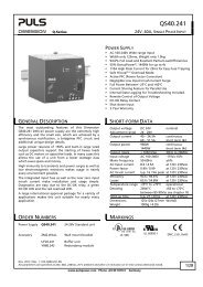
PSL File QS3_241 Last modified: 16 January 2012<br />
PSL<br />
Power Standards Laboratory<br />
www.PowerStandards.com<br />
2020 Challenger Drive #100<br />
Alameda, CA 94501 USA<br />
TEL ++1-510-522-4400<br />
FAX ++1-510-522-4455<br />
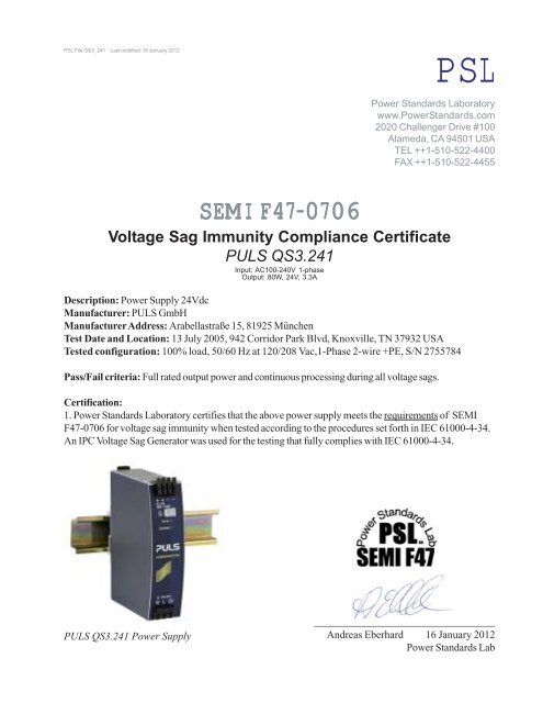
<strong>SEMI</strong> <strong>F47</strong>-<strong>0706</strong><br />
Voltage Sag Immunity Compliance Certificate<br />
<strong>PULS</strong> QS3.241<br />
Input: AC100-240V 1-phase<br />
Output: 80W, 24V, 3.3A<br />
Description: Power Supply 24Vdc<br />
Manufacturer: <strong>PULS</strong> <strong>GmbH</strong><br />
Manufacturer Address: Arabellastraße 15, 81925 München<br />
Test Date and Location: 13 July 2005, 942 Corridor Park Blvd, Knoxville, TN 37932 USA<br />
Tested configuration: 100% load, 50/60 Hz at 120/208 Vac,1-Phase 2-wire +PE, S/N 2755784<br />
Pass/Fail criteria: Full rated output power and continuous processing during all voltage sags.<br />
Certification:<br />
1. Power Standards Laboratory certifies that the above power supply meets the requirements of <strong>SEMI</strong><br />
<strong>F47</strong>-<strong>0706</strong> for voltage sag immunity when tested according to the procedures set forth in IEC 61000-4-34.<br />
An IPC Voltage Sag Generator was used for the testing that fully complies with IEC 61000-4-34.<br />
<strong>PULS</strong> QS3.241 Power Supply<br />
__________________________________<br />
Andreas Eberhard 16 January 2012<br />
Power Standards Lab
Attachment A – <strong>SEMI</strong> <strong>F47</strong> Test Results<br />
Testing was performed ESI’s Power Quality Laboratory in Knoxville, TN. The test protocol<br />
followed was <strong>SEMI</strong> F42 Test Method for Semiconductor Processing Equipment Voltage Sag<br />
Immunity. To ensure maximum accuracy of the test, a variable voltage source was used to set the<br />
voltage to exactly 120/208Vac. This was verified at the power supply with a qualified meter.<br />
During the voltage sag test, the power supply was connected to a variable resistive load bank and<br />
loaded to 100% of its load. Table A-1 shows the power supplies rated full load conditions, and<br />
the actual load it was tested at.<br />
Table A-2 lists all points tested per <strong>SEMI</strong> F42 test method, and Figure A-1 shows the power<br />
supplies specific <strong>SEMI</strong> <strong>F47</strong> ride-through curve at 120Vac, and Figure A-2 shows the power<br />
supplies specific <strong>SEMI</strong> <strong>F47</strong> ride-through curve at 208Vac. The specific <strong>SEMI</strong> <strong>F47</strong> test points<br />
are highlighted for both 50 and 60 Hz. The power supply was tested at points below the curve to<br />
fully characterize the components. During the testing of <strong>SEMI</strong> <strong>F47</strong> test points (1s at 80%, 0.5s at<br />
70%, 0.2s at 50%, and 0.05s at 50%) the output voltage of the power supply did not deviate. The<br />
power supply passed at 50 and 60 Hz, loaded to 100% of resistive load.<br />
Table A-1 Power Supplies Ratings<br />
Evaluated at 120/208Vac<br />
Manufacture Power Supply<br />
Vdc<br />
(V)<br />
I<br />
(A)<br />
R<br />
(Ohm) Watts Actual load Result<br />
<strong>PULS</strong> QS3.241 24 3.34 7.19 80 100% Passed<br />
Table A-2. <strong>PULS</strong> QS3.241 Test<br />
Results<br />
Duration<br />
Percent of Nominal<br />
60Hz 50Hz 120Vac 120Vac 208Vac 208Vac <strong>SEMI</strong><br />
Seconds Cycles Seconds Cycles 60Hz 50Hz 60Hz 50Hz <strong>F47</strong> Results<br />
1 60 1 50 50% 46% 27% 27% 80% Passed<br />
0.5 30 0.5 25 50% 46% 27% 27% 80% Passed<br />
0.5 30 0.5 25 49% 46% 27% 27% 70% Passed<br />
0.25 15 0.25 12.5 49% 45% 27% 27% 70% Passed<br />
0.2 12 0.2 10 49% 45% 27% 27% 70% Passed<br />
0.2 12 0.2 10 47% 45% 27% 27% 50% Passed<br />
0.17 10 0.17 8.5 49% 45% 27% 27% 50% Passed<br />
0.08 5 0.08 4 49% 45% 0% 0% 50% Passed<br />
0.07 4 0.07 3.5 49% 45% 0% 0% 50% Passed<br />
0.05 3 0.05 2.5 49% 49% 0% 0% 50% Passed<br />
0.03 2 0.03 1.5 0% 0% 0% 0% N/A Passed<br />
0.02 1 0.02 1 0% 0% 0% 0% N/A Passed<br />
2
Figure A-1. <strong>PULS</strong> QS3.241 <strong>SEMI</strong> <strong>F47</strong> Ride-Through Curve at 120Vac, 50 Hz and 60 Hz<br />
Semi F-47 Ride Through Curves<br />
Voltage (% of Nominal) .<br />
100%<br />
80%<br />
60%<br />
40%<br />
20%<br />
0%<br />
0 0.1 0.2 0.3 0.4 0.5 0.6 0.7 0.8 0.9 1<br />
Duration (in seconds)<br />
120V 60Hz <strong>SEMI</strong> <strong>F47</strong> 120V 50Hz<br />
Figure A-2. <strong>PULS</strong> QS3.241 <strong>SEMI</strong> <strong>F47</strong> Ride-Through Curve at 208Vac, 50Hz and 60 Hz<br />
Power Supply Semi F-47 Ride Through Curves<br />
Voltage (% of Nominal) .<br />
100%<br />
90%<br />
80%<br />
70%<br />
60%<br />
50%<br />
40%<br />
30%<br />
20%<br />
10%<br />
0%<br />
0 0.1 0.2 0.3 0.4 0.5 0.6 0.7 0.8 0.9 1<br />
Duration (in seconds)<br />
208V 60Hz <strong>SEMI</strong> <strong>F47</strong> 208V 50Hz<br />
3
Electrical Environment<br />
Steady state measurements were taken prior to testing. Table A-3 lists measurements taken to<br />
characterize the electrical environment of the power supply during <strong>SEMI</strong> <strong>F47</strong> compliance<br />
testing, at 50/60 Hz.<br />
Table A-3. Steady State Measurements for <strong>PULS</strong> QS3.241<br />
Test Process<br />
State<br />
120V/60Hz<br />
Test<br />
Process<br />
State<br />
Test<br />
Process<br />
State<br />
Test<br />
Process<br />
State<br />
120V/50 Hz 208V/60Hz 208V/50Hz<br />
Measurement Parameters<br />
Rated Voltage P-P 100-240 100-240 100-240 100-240<br />
Voltage (Va-b) 120.1 120.1 208.2 208.1<br />
Current (Ia) 1.74 1.78 0.85 0.88<br />
Power (Wa-n) 90 90 84 83<br />
Volt Amps (VA) 210 210 180 180<br />
Vthd (Phase A) % 0.97 0.86 0.52 0.33<br />
Ithd (Phase A) % 188.55 185.66 172.66 180.85<br />
I1 0.75 0.76 0.42 0.42<br />
I3 0.71 0.71 0.39 0.39<br />
I5 0.62 0.61 0.36 0.36<br />
Power Factor 0.43 0.41 0.46 0.43<br />
Crest Factors 1.44 1.43 1.42 1.42<br />
Hertz 60 50 60 50<br />
4
Attachment B - Test Configuration<br />
Test Configuration<br />
The <strong>SEMI</strong> F42 compliant voltage sag generator was placed in series with the main power feed,<br />
in according with <strong>SEMI</strong> F42 and shown in Figure B-1. The Main power feed for this test was an<br />
amplifier that was adjustable for voltage and frequency. This allowed a precise setting of<br />
120/208Vac and 50/60 Hz. A photo of the setup is shown in Figure B-2.<br />
Figure B-1 – Test Configuration and Setup<br />
120/208Vac 50/60Hz<br />
Source<br />
120/208Vac<br />
ESI<br />
Sag Generator<br />
120/208Vac<br />
Power Supply<br />
24Vdc<br />
Electronic Load Bank<br />
Configured for<br />
Resistive Load<br />
5
Figure B-2 - Photo of Test Setup<br />
6
Attachment C - <strong>SEMI</strong> <strong>F47</strong> Abstract<br />
The <strong>SEMI</strong> <strong>F47</strong> “Specification for Semiconductor Processing Equipment Voltage Sag Immunity” document defines<br />
the threshold that a semiconductor tool must operate without interruption (per <strong>SEMI</strong> F42) and it also provides a<br />
target for the facility and utility systems. The Recognizing semiconductor factories require high levels of power<br />
quality due to the sensitivity of equipment and process controls and that Semiconductor processing equipment is<br />
especially vulnerable to voltage sags, this document defines the voltage sag ride-through capability required for<br />
semiconductor processing, metrology, and automated test equipment.<br />
The requirements in this international standard were developed to satisfy semiconductor industry needs. While more<br />
stringent than existing generic standards, this industry-specific specification is not in conflict with known generic<br />
equipment regulations from other regions or generic equipment standards from other organizations. It is the intent<br />
of this standard to provide specifications for semiconductor processing equipment that will lead to improved<br />
selection criteria for sub-components and improvements in equipment systems design. While it is recognized that in<br />
certain extreme cases or for specific functions battery storage devices may be appropriate, it is not the intent of this<br />
standard to increase the size or use of battery storage devices provided with equipment. Focus on improvements in<br />
equipment component and system design should lead to a reduction or elimination in the use of battery storage<br />
devices to achieve equipment reliability during voltage sag events.<br />
The <strong>SEMI</strong> <strong>F47</strong> document specifies the minimum voltage sag ride-through capability design requirements for<br />
equipment used in the semiconductor industry. The expected equipment performance capability is shown<br />
graphically on a chart representing voltage sag duration and percent deviation of equipment nominal voltage. The<br />
primary focus for this specification is semiconductor processing equipment including but not limited to the<br />
following tool types:<br />
• Etch equipment (Dry & Wet)<br />
• Film deposition equipment (CVD & PVD)<br />
• Thermal equipment<br />
• Surface prep and clean<br />
• Photolithography equipment (Stepper & Tracks)<br />
• Chemical Mechanical Polishing equipment<br />
• Ion Implant equipment<br />
• Metrology equipment<br />
• Automated test equipment<br />
The actual <strong>SEMI</strong> <strong>F47</strong> ride-through curve is shown below.<br />
0.05<br />
100<br />
Duration of Voltage Sag in Seconds<br />
0.1 0.2 0.5<br />
1.0<br />
90<br />
Percent of Equipment Nominal Voltage<br />
80<br />
70<br />
60<br />
50<br />
40<br />
30<br />
20<br />
10<br />
0<br />
Figure C-1 The <strong>SEMI</strong> <strong>F47</strong> Voltage Sag Ride-Through Curve<br />
7
The specification states that Semiconductor processing, metrology, and automated test equipment must be designed<br />
and built to conform to the voltage sag ride-through capability per the defined curve. Equipment must continue to<br />
operate without interrupt (per <strong>SEMI</strong> E10 ) during conditions identified in the area above the defined line. In the<br />
context of <strong>SEMI</strong> <strong>F47</strong>, interrupt means any assist or failure. An assist is defined as an unplanned interruption that<br />
occurs during an equipment cycle where all three of the following conditions apply:<br />
• The interrupted equipment cycle is resumed through external intervention (e.g., by an operator or user,<br />
either human or host computer).<br />
• There is no replacement of a part, other than specified consumables.<br />
• There is no further variation from specification of equipment operation.<br />
Furthermore, a failure is any unplanned interruption or variance from the specifications of equipment operation<br />
other than assists. Although no variation in the tool’s process is the goal, this standard addresses these issues as<br />
related to the equipment operation only.<br />
8
EPRI Solutions Inc. PQ Star Certification for the Semiconductor Industry<br />
Having conducted power quality tests on hundreds of devices and electrical equipment since<br />
1992, EPRI Solutions is known worldwide for power quality testing expertise. Since April 1997,<br />
EPRI Solutions has conducted voltage sag testing on semiconductor processing tools. In order to<br />
serve the semiconductor industry, EPRI Solutions Inc. has established a certification program to<br />
test manufacturer equipment per established power quality standards. PQ Star certification for<br />
the <strong>SEMI</strong> <strong>F47</strong> standard (Specification for semiconductor Processing Equipment Voltage Sag<br />
Immunity) is now available for semiconductor equipment suppliers. EPRI Solutions utilizes the<br />
<strong>SEMI</strong> F42 test standard (Test Method for Semiconductor Processing Equipment Voltage Sag<br />
Immunity). With the PQ Star certification, EPRI Solutions Inc. offers a third party verification<br />
that the equipment tested meets this important new power quality standard.<br />
For more information about the PQ Star test program for the semiconductor industry or inquire<br />
about testing, contact Mark Stephens at mstephens@epri-solutions.com<br />
EPRI Solutions Inc.<br />
942 Corridor Park Blvd<br />
Knoxville, Tennessee 37932<br />
(865) 218-8000<br />
www.f47testing.com<br />
9