BETE HF Mitigation by Water Sprays - BETE Fog Nozzle, Inc.
BETE HF Mitigation by Water Sprays - BETE Fog Nozzle, Inc.
BETE HF Mitigation by Water Sprays - BETE Fog Nozzle, Inc.

Create successful ePaper yourself
Turn your PDF publications into a flip-book with our unique Google optimized e-Paper software.
<strong>HF</strong> <strong>Mitigation</strong> <strong>by</strong> <strong>Water</strong> <strong>Sprays</strong><br />
A Summary of Design Considerations <strong>by</strong> <strong>Nozzle</strong> Selection<br />
www.<strong>BETE</strong>.com
Table of Contents<br />
www.<strong>BETE</strong>.com<br />
<strong>HF</strong> <strong>Mitigation</strong><br />
Part I<br />
General Considerations for <strong>Mitigation</strong> of Accidental Release of Hydrogen Fluoride<br />
Introduction ....................................................................................................................2 - 9<br />
TF Series Flow rates......................................................................................................... 10<br />
Droplet Diameter Selection Guide .................................................................................... 10<br />
Droplet Diameter as a Function of <strong>Water</strong> Delivery Pressure.....................................11 - 13<br />
Part II<br />
Practical Considerations for <strong>Nozzle</strong> Selection In <strong>Water</strong> Spray <strong>HF</strong> <strong>Mitigation</strong> Systems<br />
Introduction ................................................................................................................15 - 17<br />
Effect of Sauter Mean Droplet Diameter on <strong>HF</strong> Removal Effectiveness ...................17 - 18<br />
Factors Influencing Sauter Mean Droplet Size ..........................................................18 - 20<br />
<strong>Nozzle</strong> Design ...............................................................................................18 - 19<br />
<strong>Water</strong> Supply Pressure ........................................................................................ 19<br />
<strong>Nozzle</strong> Orifice Diameter ....................................................................................... 20<br />
Emitting Spray Angle............................................................................................ 20<br />
Effect of <strong>Nozzle</strong> Array Configuration on <strong>HF</strong> Removal Effectiveness .........................21 - 22<br />
Effects of <strong>Water</strong>/<strong>HF</strong> Volumetric Ratio on <strong>HF</strong> Scrubbing Effectiveness ............................ 22<br />
Assessing Effects of Deviations from Study Parameters...........................................22 - 25<br />
General .........................................................................................................22 - 23<br />
Gas-phase/Droplet Mass Transfer Considerations.......................................23 - 24<br />
Wind Effects on Spray Performance.................................................................... 24<br />
<strong>Inc</strong>reasing Cloud Penetration........................................................................25 - 26<br />
Conclusions................................................................................................................26 - 27<br />
Acknowledgements........................................................................................................... 27<br />
References........................................................................................................................ 28<br />
The Base Case.......................................................................................................................29 - 37<br />
Appendix A: Droplet Velocity Technical Data<br />
TF 16 FCN .................................................................................................................39 - 40<br />
TF 24 FCN .................................................................................................................40 - 41<br />
TF 28 FCN .................................................................................................................42 - 43<br />
TF 32 FCN .................................................................................................................43 - 44<br />
TF 40 FCN .................................................................................................................45 - 46<br />
TF 56 FCN .................................................................................................................46 - 47<br />
Appendix B: Droplet Size Distribution Curves Technical Data<br />
TF 16 FCN .................................................................................................................49 - 51<br />
TF 24 FCN .................................................................................................................52 - 54<br />
TF 28 FCN .................................................................................................................55 - 57<br />
TF 32 FCN .................................................................................................................58 - 60<br />
TF 40 FCN .................................................................................................................61 - 63<br />
TF 56 FCN .................................................................................................................64 - 66<br />
1
www.<strong>BETE</strong>.com<br />
<strong>HF</strong> <strong>Mitigation</strong><br />
Part I<br />
General Considerations for<br />
<strong>Mitigation</strong> of Accidental Release of<br />
Hydrogen Fluoride<br />
2
www.<strong>BETE</strong>.com<br />
<strong>HF</strong> <strong>Mitigation</strong><br />
General Considerations for <strong>Mitigation</strong> of Accidental<br />
Releases of Hydrogen Fluoride<br />
Portions of the following have been abstracted from “On the Road to <strong>HF</strong> <strong>Mitigation</strong>” <strong>by</strong> R.L. Van Zele and R.<br />
Diener, Exxon Research and Engineering Co. in Florham Park, N.J. and Effectiveness of <strong>Water</strong> Spray<br />
<strong>Mitigation</strong> Systems for Accidental Releases of Hydrogen Fluoride, prepared <strong>by</strong> the Industry Cooperative <strong>HF</strong><br />
<strong>Mitigation</strong>/Assessment Program. The article originally was published in the June 1990 issue of Hydrocarbon<br />
Processing and was submitted on behalf of the ICHMAP Steering Committee.<br />
THE HAZARDS OF HYDROGEN FLUORIDE (<strong>HF</strong>) have long been recognized. However, fullscale<br />
industry-sponsored <strong>HF</strong> release tests conducted at the U.S. Department of Energy<br />
(DOE) test site in 1986 caused additional concern in view of <strong>HF</strong>’s toxicity. Ambient impacts<br />
were greater than anticipated, and diking, a primary mitigation technique, proved ineffective<br />
for releases of pressurized superheated <strong>HF</strong>.<br />
In partial response to these new technical data, an ad-hoc Industry Cooperative Hydrogen<br />
Fluoride <strong>Mitigation</strong> Assessment Program (ICHMAP) was begun in late 1987 to study and<br />
test techniques for mitigating accentual releases of <strong>HF</strong> and alkylation unit acid (AUA). AUA is<br />
a mixture of <strong>HF</strong> and hydrocarbons. It represents most of the total <strong>HF</strong> inventory of a typical <strong>HF</strong><br />
alkylation plant.<br />
The ICHMAP has recently released a report (Effectiveness of <strong>Water</strong> Spray <strong>Mitigation</strong><br />
Systems for Accidental Release of Hydrogen Fluoride) following several year’s study of<br />
water spray mitigation systems. <strong>BETE</strong> has been closely involved in this study component,<br />
providing test nozzles and the use of our lab facilities.<br />
The nozzles used in the water spray component study were the <strong>BETE</strong> TF 20 FCN and the TF<br />
16 FCN.<br />
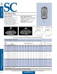
Operated at 100 psi, the TF 16 FCN will flow at 16.7 GPM and produce a spray with a Sauter<br />
Mean Diameter of approximately 210 m. Under the same conditions, the TF 20 FCN will flow<br />
26.1 GPM with a Sauter Mean Diameter of 250m.<br />
The <strong>BETE</strong> TF series spiral nozzle line produces sprays composed of droplets thirty to fifty<br />
percent smaller than conventional designs at equivalent pressures. This finely atomized<br />
spray presents an extraordinarily large amount of droplet surface area over which mass<br />
transfer can occur. The nozzles are a compact, one-piece design having no internal plates or<br />
disks.<br />
The absence of internals makes the TF series a low-maintenance unit remarkably resistant<br />
to clogging. The expanded spiral nozzles, the <strong>BETE</strong> TFXP series, achieve a free-passage<br />
diameter equal to the orifice diameter.<br />
These same outstanding performance characteristics of the <strong>BETE</strong> Spirals have earned them<br />
the recognition as the nozzle of choice for critical cooling and fire suppression appliances. In<br />
environments ranging from gas wellhead protection to the safeguarding of ship-borne<br />
ammunition magazines, the <strong>BETE</strong> Spirals are providing unmatched fire control and cooling<br />
capabilities.<br />
3
The assessment<br />
www.<strong>BETE</strong>.com<br />
<strong>HF</strong> <strong>Mitigation</strong><br />
ICHMAP screened numerous potential mitigation techniques for accidental <strong>HF</strong> releases.<br />
<strong>Inc</strong>luded were techniques such as total enclosures with exhaust scrubbers, liquid<br />
containment dikes, form application, water sprays, vapor barriers, and surface tension<br />
modifying agents.<br />
<strong>Water</strong> sprays and vapor barriers were judger the most promising for additional research.<br />
ICHMAP mitigation components consisted of both water spray and vapor barrier programs.<br />
The water spray program investigated the effectiveness of water or augmented water<br />
application systems in mitigation accidental releases of both <strong>HF</strong> and AUA. The vapor barrier<br />
program assessed the effectiveness of vapor barriers in delaying and diluting accidental<br />
releases of heavier-than-air <strong>HF</strong> vapor clouds in an industrial setting. The program also<br />
determined what impact such barriers might have on the consequences of an unconfined<br />
vapor cloud explosion.<br />
Major Conclusions:<br />
• <strong>Water</strong>, applied via either fixed sprays or fire monitors, is effective in removing <strong>HF</strong>, <strong>HF</strong><br />
removals of 25% to 90+% were demonstrated at water-to-<strong>HF</strong> liquid volume ratios of 6/1/<br />
to 40+/1.<br />
• Vapor fences can reduce near-field concentrations, but will have little effect on far-field<br />
concentrations and will have little effect on cloud arrival and departure times.<br />
• Vapor boxes (four-sided enclosures with an open top) can reduce both near and far-field<br />
concentrations. Far-field concentration reductions are the result of a reduction in the rate<br />
of gas being advected downwind. However, such vapor boxes will appreciably increase<br />
the consequences of an unconfined vapor cloud explosion in the event of a flammable<br />
gas release.<br />
• Large plant obstacles reduce downwind concentration.<br />
• Concentration reductions resulting from large plant obstacles or vapor fences/boxes are<br />
very site-specific.<br />
Background<br />
Sound practices for handling <strong>HF</strong> are in place. The hazards have long been recognized in<br />
operating practices have been aimed at minimizing the possibility of a release and mitigating<br />
the effects if one should occur.<br />
Prior to 1986, accidental releases of pressurized, superheated <strong>HF</strong> were commonly thought to<br />
form liquid pools. This led to the concept that liquid containment dikes could mitigate the<br />
ambient impacts of accidental <strong>HF</strong> releases.<br />
In the summer of 1986, a series of atmospheric <strong>HF</strong> release tests were conducted at the DOE<br />
test site in Mercury, Nevada (codenamed the GOLDFISH series). These tests concluded that<br />
a release of pressurized, superheated <strong>HF</strong> did not pool, negating the benefit of liquid<br />
containment dikes. Further, the resultant ambient impacts were greater than anticipated<br />
because the vapor clouds advected downwind consisted of flashed <strong>HF</strong> vapor and entrained<br />
<strong>HF</strong> liquid as a finely disperses aerosol. In addition, the GOLDFISH tests demonstrated that<br />
water sprays were at least partially effective in mitigating such releases of <strong>HF</strong>.<br />
ICHMAP was formally established in December 1987 to develop information to better design<br />
and implement effective mitigation techniques for accidental releases of <strong>HF</strong>, and a computer<br />
4
<strong>Water</strong> Spray Component<br />
www.<strong>BETE</strong>.com<br />
<strong>HF</strong> <strong>Mitigation</strong><br />
tool to better estimate ambient impacts from accidental <strong>HF</strong> releases. ICHMAP involved 20<br />
companies, both <strong>HF</strong> producers and consumers (Allied-Signal, Amoco, Ashland, BP, Chevron,<br />
Conoco/DuPont, Dow, Elf Aquitaine, Exxon, Kerr-McGee, Marathon, Mobil, Phillips, Saras,<br />
Shell International, Sun/Suncor, Tenneco, Texaco, Unocal, and 3M).<br />
Program components and their major objectives were:<br />
• <strong>Water</strong> Spray. Investigate the effectiveness of water or augmented water application<br />
systems in mitigating accidental releases of both <strong>HF</strong> and AUA.<br />
• Vapor barrier. Assesses the effectiveness of vapor barriers in delaying and diluting<br />
accidental releases of heavier-than-air <strong>HF</strong> vapor clouds in an industrial setting and<br />
determine what impact such barriers might have on the consequences of an unconfined<br />
vapor cloud explosion.<br />
• Impact Assessment. Develop validated ambient impact assessment computer models<br />
for calculating release rates and jet and plume dispersion of accidental releases of <strong>HF</strong>.<br />
The objective was to investigate the effectiveness of water or augmented water application<br />
(via either sprays or monitors) in mitigating accidental releases of both <strong>HF</strong> and AUA as a<br />
function of flow conditions, <strong>HF</strong> acid and water spray properties, and geometric factors.<br />
Augmented water refers to water plus additives such as sodium bicarbonate, caustic, or<br />
surfactant. This work was in large part a follow-up to the 1986 GOLDFISH series.<br />
GOLDFISH included three water spray tests that demonstrated 35% to 55% <strong>HF</strong> removal<br />
efficiency. These tests provided valuable information, but they were limited in scope and<br />
detail. Several key questions went unanswered.<br />
A series of bench-scale laboratory and larger-scale field tests were conducted in controlled<br />
humidity/wind speed flow chambers. The bench-scale experiments identified key variables<br />
for testing in larger-scale field tests. In the larger-scale field tests, <strong>HF</strong> and AUA removal<br />
efficiencies were measured as a function of variables such as water-to-<strong>HF</strong> liquid ratio, water<br />
application method (sprays, fire monitors), water additives (neutralizing agents, surfactants),<br />
distance of the water application to the release point, water application droplet size, ambient<br />
relative humidity, etc.<br />
It was outside the scope of this work to generate generic design criteria for water mitigation<br />
systems, since each application depends on many local factors. However, conclusions can<br />
guide those responsible for designing mitigation systems. To this end, two separate computer<br />
models were developed to assist in assessing the effect of various water application design<br />
parameters on <strong>HF</strong> removal efficiency.<br />
Overview, lab test program<br />
The objective of the small-scale laboratory test program was to help define the test matrix for<br />
the larger scale field-testing, to evaluate design criteria for a larger flow chamber, and to gain<br />
operating experience with <strong>HF</strong> and AUA for the larger unit.<br />
Among key variables identified, the water flow rate at a constant acid flow rate was clearly the<br />
dominant variable. In addition, <strong>HF</strong> removal efficiency increases as droplet size of the water<br />
spray decreased. Among various water additives tested, which included NaHCO 3 , CaCl 2 ,<br />
NaOH, and surfactant, only NaOH shower a marginal increase in removal efficiency<br />
compared to pure water.<br />
5
Overview, field test program<br />
www.<strong>BETE</strong>.com<br />
<strong>HF</strong> <strong>Mitigation</strong><br />
A series of 87 large-scale field tests was conducted in which the effect of major variables on<br />
the <strong>HF</strong> removal efficiency of water or augmented water, applied via either sprays of a fire<br />
monitor, was determined. This test series also included seven tests in which aerosol particle<br />
sizes were measured.<br />
The 87 tests were conducted at DOE’s liquefied gaseous fuels spill test facility, near the<br />
Mercury, Nev. test site. They were termed the HAWK series.<br />
Pressurized, superheated <strong>HF</strong>, either in pure anhydrous form or in the form of AUA, was<br />
released at controlled pressure and temperature into a totally enclosed flow chamber (14-0<br />
feet long, 16 feet high, 8 feet wide) and contacted with water or augmented water.<br />
In the chamber, water was applied via either sprays or a fire monitor. The <strong>HF</strong> was released<br />
from a square-edged orifice at a normal rate of approximately 6 gpm. Steam and water spray<br />
grids at the chamber inlet allowed for control of both air humidity and temperature. In<br />
addition to releases of pressurized <strong>HF</strong>, several tests were conducted to assess the <strong>HF</strong><br />
removal efficiency of water sprays for <strong>HF</strong> pool evaporation releases.<br />
Impact of variables<br />
The impact of the following variables on <strong>HF</strong> removal efficiency was determined:<br />
• <strong>Water</strong> liquid volume ratio<br />
• <strong>Water</strong> spray application geometry:<br />
• Number of sprays per header<br />
• Spray header distance from the release point<br />
• Spray orientation (up flow and down flow)<br />
• Spray header elevation above the release point<br />
• Dual spray headers in series<br />
• <strong>Water</strong> spray droplet size<br />
• <strong>Water</strong> application via a fire monitor:<br />
• Application pattern (fog or jet)<br />
• Monitor distance from the release point<br />
• Acid type (anhydrous <strong>HF</strong> or AUA)<br />
• Acid temperature, pressure<br />
• <strong>Water</strong> additives (NaHCO3, surfactant, NaOH)<br />
• Ambient relative humidity and wind speed<br />
• Steam as an acid jet dispersant<br />
In addition to measuring <strong>HF</strong> removal efficiency, seven tests were conducted in which the size<br />
of the <strong>HF</strong> aerosol particles (Liquid <strong>HF</strong> entrained with the flashed vapor was measured using a<br />
particle counter sizer velocimeter (PCSV). The PCSV is a laser-based light scattering<br />
instrument which makes direct in-line particle size measurements.<br />
6
www.<strong>BETE</strong>.com<br />
<strong>HF</strong> <strong>Mitigation</strong><br />
Aerosol droplet measurements<br />
In addition to the water application mitigation tests, a series of tests was conducted in the<br />
large-scale flow chamber to measure the size of the aerosol droplets produced when<br />
pressurized, superheated <strong>HF</strong> or AUA is released into the atmosphere.<br />
To briefly summarize the results, the PCSV-P measured predominantly submicron liquid<br />
aerosol droplets at the exit of the sharp-edged discharge orifice. The aerosol droplets<br />
subsequently grew to larger particles at the outlet of the flow chamber. The presence of<br />
submicron particles at the orifice exit point to formation of aerosol <strong>by</strong> the process of flash<br />
atomization breakup as opposed to conventional shear spray breakup. Temperature,<br />
humidity, release pressure, radial position in the plume, and type of acid did not appear to<br />
have any significant effect on the measured size distributions for the range of conditions<br />
investigated. The increase in droplet size at the exit of the chamber is likely due to the<br />
condensation of ambient moisture resulting from contact with the cold <strong>HF</strong> plume.<br />
Damage tests with monitors<br />
Applying mitigation water <strong>by</strong> fire monitors raises the concern of damage to the unit resulting<br />
from rapid activation and application of high pressure, large-volume water monitors. To help<br />
assess how serious this concern might be, a series of tests was conducted in which water<br />
was applied via fire monitors at rates of 2,000, 4,000, and 6,000 gpm at distances of 7, 15,<br />
and 25 feet from the process unit.<br />
The target area included pressure gauges, small-bore piping, control valve stations, and<br />
conduit. <strong>Water</strong> was applied via both a wide-angle fog pattern and a straight jet pattern. The<br />
water delivery pressure was approximately 100 psig.<br />
In the most severe test, water was applied in a narrow jet pattern at a rate of 6,000 gpm at a<br />
distance of 7 feet from the target area. The resulting damage to the target area was minimal.<br />
It consisted mainly of broken pressure gauge glasses, dented insulation, and some loosening<br />
of conduit from its supports. The overall integrity of the target area was not affected, i.e.,<br />
there was no broken piping of instrument tubing.<br />
Summary of Conclusions<br />
Major conclusions from the large-scale field tests are:<br />
• <strong>Water</strong>-to <strong>HF</strong> liquid volume ratio was identified as the major variable affecting removal<br />
efficiency.<br />
• <strong>HF</strong> removal of 25% to 90%+ were demonstrated at water-to-<strong>HF</strong> liquid volume ratios of<br />
6/1 to 40+/1. For comparisons of <strong>HF</strong> removal efficiency versus water-to-<strong>HF</strong> liquid volume<br />
ratio, a base case was defined with down flow sprays at 8 feet elevation located 16 feet<br />
from release point, 320 micron Sauter mean water spray droplet diameter, anhydrous <strong>HF</strong>.<br />
• <strong>Water</strong> additives (neutralizing agents, surfactants, etc.) and steam as a jet dispersant had<br />
little measurable effect on removal efficiency.<br />
7
www.<strong>BETE</strong>.com<br />
<strong>HF</strong> <strong>Mitigation</strong><br />
• <strong>Water</strong> spray removal efficiency increased with:<br />
o Decreased water spray droplet size nozzles<br />
o <strong>Inc</strong>reasing distance between the spray nozzles (2 feet or 3 feet nozzle spacing<br />
versus 1 foot in the base case)<br />
o Decreasing spray header elevation above the release point (16 feet versus 8 feet<br />
in the base case)<br />
• Dual water sprays (i.e., two spray headers in series, separated <strong>by</strong> approximately 15 feet)<br />
had little measurable effect on <strong>HF</strong> removal efficiency at a constant total water-to-<strong>HF</strong> liquid<br />
volume ratio.<br />
• <strong>HF</strong> storage pressure appeared to affect <strong>HF</strong> removals, but adequate data were not<br />
collected to isolate the potential effect of other variables.<br />
• Applications where the acid release elevation was at the same level as the spray headers<br />
causes severe <strong>by</strong>passing of the acid cloud over the header. This resulted in expectedly<br />
substantial reductions in removal efficiencies.<br />
• A trend was measured of increasing efficiency with acid pressure. A number of<br />
unmeasured variables related to liquid dropout render these tests inconclusive.<br />
• Up flow water sprays provided slightly higher removals than did down flow water sprays.<br />
These gains may not be additive to the gains from droplet size reduction.<br />
• There was essentially no difference in <strong>HF</strong> removal efficiencies between <strong>HF</strong> and AUA for<br />
a constant water-to-total contained <strong>HF</strong> acid liquid volume ratio.<br />
• Wind speed and relative humidity had little measurable effect on removal efficiency under<br />
the conditions tested (50%-90% R.H.; 3.0 to 6.0 meters per second).<br />
• A fire monitor provided better <strong>HF</strong> removals when operated with a coarse droplet jet<br />
pattern aimed directly at the release point from a short distance (as opposed to a wide<br />
fog pattern or a jet applied from a greater distance).<br />
• Aerosol produced at the exit of the release orifice was predominantly sub-micron in size.<br />
The aerosol particle size was unaffected <strong>by</strong> acid pressure, acid type, acid temperature, or<br />
relative humidity.<br />
Application of test results<br />
In applying the results of this work to conditions different from those in the field tests, due<br />
account must be taken of the dynamic interaction between the water spray and the HD cloud.<br />
Work has recently been completed <strong>by</strong> ICHMAP’s <strong>Water</strong> Spray Subcommittee to characterize<br />
these interactions. Two separate computer models have been developed to assess the effect<br />
of various design parameters such as water-to-<strong>HF</strong> liquid volume ratio, distance of the water<br />
application from the release point, water application method (i.e., up flow or down flow of<br />
sprays, fire monitors, etc), on overall <strong>HF</strong> removal efficiency.<br />
8
www.<strong>BETE</strong>.com<br />
<strong>HF</strong> <strong>Mitigation</strong><br />
The Base Case<br />
Down flow, single curtain<br />
No additives<br />
Saunter Mean Droplet Diameter of 320 microns<br />
Spray 16 feet downstream of acid orifice<br />
Acid orifice elevation at 3 feet<br />
Spray header elevation at 8 feet<br />
Eight (8) spray nozzles<br />
No steam dispersion of acid<br />
Acid pressure of 60 psig<br />
Acid temperature of 100ºF<br />
Air velocity of 3.0 meters per second<br />
Figure 1. Field <strong>HF</strong> <strong>Water</strong> Spray Study, base case<br />
9
www.<strong>BETE</strong>.com<br />
<strong>HF</strong> <strong>Mitigation</strong><br />
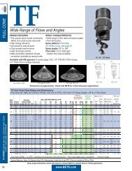
TF Series<br />
10
www.<strong>BETE</strong>.com<br />
<strong>HF</strong> <strong>Mitigation</strong><br />
TF 16 FCN<br />
Droplet Diameters as Function of <strong>Water</strong> Delivery Pressure<br />
TF24FCN<br />
Droplet Diameters as Function of <strong>Water</strong> Delivery Pressure<br />
11
www.<strong>BETE</strong>.com<br />
<strong>HF</strong> <strong>Mitigation</strong><br />
TF 32 FCN<br />
Droplet Diameters as Function of <strong>Water</strong> Delivery Pressure<br />
TF 40 FCN<br />
Droplet Diameters as Function of <strong>Water</strong> Delivery Pressure<br />
12
www.<strong>BETE</strong>.com<br />
<strong>HF</strong> <strong>Mitigation</strong><br />
TF 56 FCN<br />
Droplet Diameters as Function of <strong>Water</strong> Delivery Pressure<br />
13
www.<strong>BETE</strong>.com<br />
<strong>HF</strong> <strong>Mitigation</strong><br />
Part II<br />
Practical Considerations for<br />
<strong>Nozzle</strong> Selection in<br />
<strong>Water</strong> Spray <strong>HF</strong> <strong>Mitigation</strong> Systems<br />
14
www.<strong>BETE</strong>.com<br />
<strong>HF</strong> <strong>Mitigation</strong><br />
<strong>by</strong><br />
James P. Slavas<br />
<strong>BETE</strong> <strong>Fog</strong> <strong>Nozzle</strong>, <strong>Inc</strong>.<br />
Greenfield, Massachusetts<br />
Practical Considerations for <strong>Nozzle</strong> Selection in <strong>Water</strong><br />
Spray <strong>HF</strong> <strong>Mitigation</strong> Systems<br />
January 25, 1991<br />
Prepared for Presentation at the PETRO-SAFE ’91 Conference<br />
Houston, Texas<br />
February 6-8, 1991<br />
15
www.<strong>BETE</strong>.com<br />
<strong>HF</strong> <strong>Mitigation</strong><br />
Abstract<br />
Recent theoretical and experimental studies have shown that appropriately configured water<br />
sprays can be highly effective in mitigating the effects of accidental releases of pressurized,<br />
super-heated hydrogen fluoride (<strong>HF</strong>) and alkylation unit acid (AUA) [Fthenakis 1989, 1990;<br />
Schatz et al, 1989]. Large-scale studies have quantified the impact of numerous variables on<br />
<strong>HF</strong> removal efficiencies. For volumetric water to <strong>HF</strong> liquid ratios of 6:1 to 40:1, <strong>HF</strong> removal<br />
efficiencies of 35% to 90% have been demonstrated [Schatz et al, 1989].<br />
Applying these study results to actual mitigation system design requires an appreciation of<br />
the complex interactions between acid mass transfer and nozzle design, operating<br />
parameters and nozzle-array placement and configuration. Effects of nozzle design, spray<br />
droplet size and spray angle on <strong>HF</strong> scrubbing effectiveness are discussed.<br />
Additional considerations of wind effects on water spray gas cloud penetration in moderate<br />
wind conditions 3.0 to 15.0 meters per second (7 to 24 MPH) are elucidated.<br />
16
www.<strong>BETE</strong>.com<br />
<strong>HF</strong> <strong>Mitigation</strong><br />
1. Introduction<br />
The report The Effectiveness of <strong>Water</strong> Spray <strong>Mitigation</strong> Systems for Accidental Releases of<br />
Hydrogen Fluoride prepared <strong>by</strong> the Industry Cooperative <strong>HF</strong> mitigation/Assessment Program<br />
(1989, hereafter referred to as the “Study”) quantified the impact of numerous variables on<br />
the <strong>HF</strong> removal effectiveness of water sprays [figure 1].<br />
Of the number of variables impacting the efficacy pf the <strong>HF</strong> mitigation investigated within the<br />
scope of the Study, three of these variables are particularly sensitive to spray nozzle<br />
performance:<br />
• Sauter Mean droplet diameter<br />
• Volumetric ratios (water/<strong>HF</strong>)<br />
• Placement and configuration of arrays<br />
Generating applicable design specifications for general <strong>HF</strong> mitigation systems was outside<br />
the scope of this Study. Local factors such as risk assessment studies, environmental and<br />
regulatory issues, unit size, type and location, existing firewater and spray systems will all<br />
impact the final system design.<br />
Applying these study results to the selection of specific nozzle types and array geometries<br />
requires an appreciation of the interrelation between nozzle design/operating parameters and<br />
nozzle performance in terms of atomization, spray coverage and overall <strong>HF</strong> scrubbing<br />
effectiveness.<br />
When evaluating initial designs for a water spray <strong>HF</strong> mitigation system. The effect of local<br />
winds on the development of spray patterns and spray penetration into the acid cloud must<br />
be assessed. Modifications to the array configurations and nozzle spacings considered in the<br />
Study may be prudent in order to minimize acid cloud <strong>by</strong>-passing while maintaining high<br />
levels of acid mass transfer.<br />
While it is tempting to reduce the Study’s conclusions to a simple rule-of-thumb involving the<br />
number of gallons of water to be sprayed per gallon of <strong>HF</strong> released, the overall <strong>HF</strong> scrubbing<br />
effectiveness is highly sensitive to a number of other variables. Additional trade-offs may be<br />
required between the fine spray atomization the Study demonstrated to be effective for high<br />
<strong>HF</strong> removal levels and the nozzle characteristics needed to reduce system complexity,<br />
maximize reliability under adverse environmental conditions and resist cross-wind induced<br />
spray pattern deformation.<br />
2. Effect of Sauter Mean Droplet Diameter on <strong>HF</strong> Removal Effectiveness<br />
A nozzle produces a spray composed of a range of droplet sizes (diameters). When we talk<br />
of a nozzle producing droplets of a given diameter, we are really discussing a drop size that<br />
somehow characterizes the varied droplet sizes making up the spray volume. While there are<br />
at least seven different commonly employed definitions used to characterize spray droplet<br />
diameters, the Sauter Mean Diameter (D32) is the best indicator of a spray’s performance in<br />
processes involving complex interactions with the droplets’ surface and volume, such as<br />
spray drying, evaporative cooling, dry scrubbing, gas quenching and gas absorption.<br />
Sometimes abbreviated to S.M.D. the Sauter Mean is the diameter of a droplet whose ratio of<br />
volume to surface area is equal to that of the complete spray sample. It is defined as the<br />
cube of the Volume Mean Diameter (DV30) divided <strong>by</strong> the square of the Surface Mean<br />
Diameter (DV20).<br />
2.0.01. D 32 = (D V30 ) 3 / (D V20 )2<br />
17
www.<strong>BETE</strong>.com<br />
<strong>HF</strong> <strong>Mitigation</strong><br />
The Sauter Mean diameter is typically 80% of the Volume Median diameter (DV0.5).<br />
Sometimes abbreviated V.M.D. or M.V.D., the Volume (or Mass) Median Diameter (DV0.5)<br />
divides the volume (or mass) of the spray into two equal halves. Thus, one-half of the total<br />
volume (or mass) is composed of droplets smaller than the Volume Median diameter, and<br />
half of diameters larger than the Volume Median Diameter. The DC0.5 droplets are often<br />
modeled to define the spray envelope for combinations of nozzles and operating conditions.<br />
The Study found a strong correlation between decreasing spray Sauter Mean (D32) droplet<br />
diameters and increasing scrubbing efficiencies [figure 2].<br />
Decreasing the D32 from the Base Case 320µm resulted in an increase of scrubbing<br />
efficiency from 53% to 72% at a water/<strong>HF</strong> ratio of 15:1 (vol/vol) [Study, tests 15, 16 &20].<br />
Reduction of the Sauter Mean diameter can be accomplished <strong>by</strong> several strategies:<br />
• Optimize nozzle design for atomization performance<br />
• <strong>Inc</strong>rease water supply pressure<br />
• Decrease orifice diameter<br />
• <strong>Inc</strong>rease spray angle<br />
In conditions of moderate wind, these strategies can have adverse impacts on spray<br />
penetration into the gas cloud. Significant spray pattern deformation and droplet entrainment<br />
can occur; allowing portions of the gas to <strong>by</strong>pass the spray and reducing the acid mass<br />
transfer to the droplets.<br />
3. Factors Influencing Sauter Mean Drop Size<br />
3.1 <strong>Nozzle</strong> Design<br />
<strong>Nozzle</strong> design has considerable influence on spray droplet size. Ignoring performance<br />
variations within each nozzle type, direct pressure spray nozzles can be ranked as follows (in<br />
order of increasing droplet size):<br />
<strong>Nozzle</strong> Type<br />
Relative D32<br />
(1.0 = spirals)<br />
Spiral Impingement 1.0<br />
Turbine Whirl 1.3<br />
Wide-angle Whirl Tangential 1.35<br />
Disk Whirl 1.7<br />
Flat Fan 2.0<br />
Narrow-angle Whirl Tangential 2.4<br />
Impingement Flat Fan 2.5<br />
[figure 5]<br />
At a given supply pressure, the most cost-effective means of lowering the D32 of a spray is to<br />
utilize nozzle designs optimized for atomization efficiency.<br />
The spiral impingement nozzle type produces the finest atomization of any direct-pressure<br />
nozzle. Selecting a spiral impingement design over the typical full-cone whirl type will result in<br />
a 30-50% reduction in D32 diameters at equivalent flow and pressure conditions. This smaller<br />
D32 translates into 2 to 3.3 times the available droplet surface area produced <strong>by</strong> the whirl<br />
nozzle type at equivalent flow and pressure conditions.<br />
18
www.<strong>BETE</strong>.com<br />
<strong>HF</strong> <strong>Mitigation</strong><br />
<strong>BETE</strong> <strong>Fog</strong> <strong>Nozzle</strong> has been involved in a number of studies and development projects<br />
concerning fire and explosion suppression, control and prevention.<br />
We developed the spiral impingement design specifically for these applications. The spiral<br />
design is a significantly finer atomizer than the traditional whirl type, producing sprays thirty to<br />
fifty percent finer for equivalent flow, pressure and spray angle.<br />
The nozzles are a compact, rugged, one-piece design having no internal plates or disks. The<br />
absence of internals makes the spiral design a low-maintenance unit remarkably resistant to<br />
clogging.<br />
The design of the “full-cone” spiral nozzle develops concentric dense rings of highly atomized<br />
liquid, with unique reduced-pressure inter-cone volumes filled with the more finely atomized<br />
liquid. This finely atomized spray presents an extraordinarily large amount of droplet surface<br />
area over which acid mass transfer can occur. These fines are very effectively restraining<br />
within the inter-cone volumes, allowing for prolonged intimate liquid-gas contact even under<br />
adverse wind and thermal convection conditions.<br />
By contrast, whirl nozzles create sprays in which the droplet fines are located at the outer<br />
spray cone surfaces. These fines rapidly become de-coupled from the main spray volume<br />
and are extremely vulnerable to entrainment <strong>by</strong> wind and thermal convection. Under even<br />
light wind conditions, these fines are thus effectively removed from participation in <strong>HF</strong><br />
absorption.<br />
At elevated pressures, the reduced pressure zones within the spray pattern produced <strong>by</strong> the<br />
spiral impingement nozzle are significantly enhanced. These larger pressure differentials can<br />
reduce the effective angle of the spray and cause the adjacent cones of narrow-angle spiral<br />
nozzles to combine.<br />
The spiral nozzles are highly efficient; having discharge coefficients of between 0.94 and<br />
0.97, with exist velocities approaching the theoretical values predicted <strong>by</strong> Benoulli:<br />
3.1.01 U = C D (2gH) 0.5<br />
The Study’s authors for the main water spray study component chose the spiral impingement<br />
nozzle design. Because of their documented effectiveness in <strong>HF</strong> mitigation and the clear<br />
performance advantages of the spiral over tradition al whirl nozzles, the spiral impingement<br />
design is indicated for use in water-pray <strong>HF</strong> mitigation systems.<br />
3.2 <strong>Water</strong> Supply Pressure<br />
Droplet size varies inversely approximately as the 0.3 power of the source pressure. Among<br />
the various nozzle types, this exponent can easily range from –0.2 to –0.4. For the spiral<br />
impingement design, a pressure exponent of –0.3 can be reasonably used. A fifty percent<br />
reduction is D32 diameter would require approximately a tend-fold increase in operating<br />
pressure for a given spiral impingement nozzle.<br />
Although the D32 diameters can be reduced <strong>by</strong> increasing the supply pressure at the<br />
nozzles, line losses, design and capital costs considerations typically constrain the maximum<br />
available pressure in large-scale installations to under 150 psig at the nozzles. Other<br />
concurrent uses of the supply lines (fire monitors, hose reels, wash-down lines) will often<br />
reduce worst-case supply pressures to 60-80 psig at the nozzles.<br />
19
3.3 <strong>Nozzle</strong> Orifice Diameter<br />
www.<strong>BETE</strong>.com<br />
<strong>HF</strong> <strong>Mitigation</strong><br />
Droplet size can vary directly as the 0.8 power of the orifice diameter. There is a wide<br />
variation in this exponent among the various nozzle designs. This value can range from 0.3 to<br />
1.2. Spiral impingement nozzles are characterized <strong>by</strong> an orifice exponent of 0.8 while<br />
traditional whirl nozzles range down 0.5. A fifty percent reduction in D32 can be achieved with<br />
an orifice ratio of 1:2:4 for the spiral design. The whirl-type nozzles require up to a 1:4 orifice<br />
ratio to achieve an equivalent drop size reduction.<br />
Decreases in D32 diameters achieved <strong>by</strong> reducing the nozzle orifice diameter will also<br />
decrease the flow per nozzle. Additional nozzles need to be provided in order to maintain the<br />
design <strong>Water</strong>/<strong>HF</strong> volumetric flow ratio.<br />
The nozzles in a water spray system need to be protected from pluggage <strong>by</strong> entrained<br />
particulates (sand, rust scale, algae, invertebrates, etc.) <strong>by</strong> adequate screening or filtering of<br />
the water supply. “Adequate” is generally considered to imply removal of particulates with<br />
diameters exceeding 50% of the minimum nozzle passageway (“free passage diameter”).<br />
Providing individual strainers for each nozzle is not a practical strategy for large-scale<br />
installations due to maintenance, inspection and cost constrains. The typical approach<br />
locates coarse screen strainers at the mains/branch intersections. Somewhat finer screening<br />
is provided at the branch/one intersections with the final target screen sizes used to protect<br />
the individual array headers. The nozzles are therefore liable to plugging from particulates<br />
generated downstream from the final strainer. To prevent external nozzle pluggage at<br />
installations within the ranges of mud wasps and other similar nuisance pests, the nozzles<br />
should be provided with blow-off protective covers.<br />
Under outdoor field conditions, pluggage and maintenance concerns will generally limit orifice<br />
(or more critically, free passage) diameters to the range of 0.125” (<strong>BETE</strong> TF 16 FCN) and<br />
0.187” (<strong>BETE</strong> TF 20 FCN). The large free passage versions of these nozzles have free<br />
passages of 0.250” and 0.313” respectively.<br />
3.4 Emitting Spray Angle<br />
Droplet size can vary inversely as the 0.25 power of the tangent of the ½ cone angle for<br />
reasonable changes in angle. The spiral impingement design produces the finest sprays<br />
when designed for an emitting angle of 120º to 140º. Above 150º, the spirals can evidence a<br />
rapid coarsening of the spray. Whirl nozzles also tend to produce the finest sprays within the<br />
120º to 140º range, while limitations inherent to the type generally constrain emitting angles<br />
to under 135º.<br />
Decreasing the spray angle from 120º to 90º entails a drop size penalty of approximately 15%<br />
for the spiral impingement nozzles.<br />
At pressures above 60 psi, spiral impingement nozzles with emitting angles less than 80º<br />
evidence a melding of their component cones. This effect eliminates the reduced-pressure<br />
inter-core volumes that are normally filled with droplet “fines.” Most of these fines will migrate<br />
into the center volume at higher pressures, but up to 30% can be driven to the outer cone<br />
surface. The nozzle becomes effectively a wide-band hollow-cone nozzle.<br />
For this reason, further reduction below 90º in spray emitting angle should not generally be<br />
considered an effective strategy for enhancing in-the-field <strong>HF</strong> scrubbing efficiency when<br />
using spiral impingement nozzles.<br />
20
www.<strong>BETE</strong>.com<br />
<strong>HF</strong> <strong>Mitigation</strong><br />
4. Effect of <strong>Nozzle</strong> Array Configuration on <strong>HF</strong> Removal Effectiveness<br />
The Study concluded, “…that up-flow improves the efficiency in the lower range of water/<strong>HF</strong><br />
ratio, while at higher ratios the effect of up-flow becomes inconclusive or negligible” [Study,<br />
p.166 Detailed Report]. The increase in efficiency does not appear to be proportional to the<br />
increase in residence time of the droplets within the <strong>HF</strong> cloud. The Study surmises<br />
equilibrium in the acid mass transfer, which may be partially due to the low relative velocity of<br />
the droplets during much of their residence within the acid cloud. Fthenakis (1990) indicates<br />
lower absorption effectiveness for all directions of sprays other than vertical downward.<br />
The Study also concludes a small detrimental effect on scrubbing efficiency with increasing<br />
nozzle elevation above the <strong>HF</strong> release point [p.167 ibid].<br />
Additional effects of miscellaneous geometry changes show that two headers located 5<br />
meters and 10 meters (16’0 and 32’0) downstream of, and 2.4 meters (8’0) above the <strong>HF</strong><br />
source are nearly as effective as the Base Case (single header at 16’0) as is a dual curtain of<br />
up-and-down spraying nozzles at 32’0 distance. The Study showed excessive <strong>by</strong>passing of<br />
the <strong>HF</strong> cloud over the spray header (and substantially lower removal efficiency) when both<br />
the <strong>HF</strong> orifice and spray header were located at a 2.4 meter (8’0) elevation. Similarly,<br />
<strong>by</strong>passing of the cloud through the open areas around the two single-nozzle sprays [Study,<br />
tests 19 and 62] led to a compensating effect on scrubbing efficiency [p.168 ibid].<br />
Given the increased spray coverage attainable, a vertical downward spray orientation is<br />
indicated for the majority of outdoor installations. For the <strong>BETE</strong> TF 20 FCN the vertical down<br />
spray orientation penetrates 80% further than the vertical up spray in the 3 meters per<br />
second cross-flow investigated <strong>by</strong> the Study [figures 6, 7].<br />
<strong>Nozzle</strong>s mounted so as to spray vertically upward can be placed to advantage, in conjunction<br />
with vertical down arrays, at identified potential point-source leaks and at locations where<br />
minimum height clearances require overhead arrays to be mounted at elevations above that<br />
which would otherwise be considered prudent.<br />
For <strong>HF</strong> mitigation systems designed for winds of 3.0 meters per second (7 MPH) and under,<br />
a vertical mounting of 2.4 meters (8’) above the potential leak source appears reasonable<br />
[figure 6] when nozzles with equivalent performance to the TF 20 FCN considered in the<br />
Study are operated at 100 psi. As shall be discussed, higher design wind speeds may<br />
indicate narrowed vertical spacing of the spray headers.<br />
The Study results indicate essentially equivalent scrubbing effectiveness between the spray<br />
headers located at 5 meters (16’0) and those 10 meters (32’0) downstream of the <strong>HF</strong> release<br />
point.<br />
The location of the water spray header arrays depends upon the nature of the potential <strong>HF</strong><br />
release sites, whether they be point source or wide area. Isolated point sources can probably<br />
be most easily protected with individual arrays located 5 meters to 10 meters (16’0 t 32’0)<br />
about the release sites. Where the number of potential release sites is large, or of an areawide<br />
nature, arrays ranged about the perimeter of the site may be more cost effective.<br />
The Study demonstrated an understandable sensitivity of <strong>HF</strong> scrubbing effectiveness to acid<br />
cloud <strong>by</strong>passing; the spray headers should be mounted above the leak elevation. Utilizing<br />
two staggered sets of arrays separated horizontally <strong>by</strong> slightly less than the spray pattern<br />
effective diameter will minimize <strong>by</strong>passing through the open triangles on either side of the<br />
individual sprays [Study, p. 268, Detailed Report].<br />
21
www.<strong>BETE</strong>.com<br />
<strong>HF</strong> <strong>Mitigation</strong><br />
The Study showed an apparent advantage to nozzle spacing along the headers of 0.6 meters<br />
(2’0) and 1 meters (3’0) over the 0.3-meter (1’0) Base Case spacing. It is most probable that<br />
air eduction and induced turbulence within the gas field are the primary contributors to this<br />
effect. If the selected nozzles can generate an adequately wide spray pattern under design<br />
wind velocities, wider nozzle spacing along the headers is indicated.<br />
To minimize <strong>by</strong>passing, the spray patterns must show some degree of overlap. For the TF 20<br />
FCN studied, a 1-meter (3’0) c.c. spacing yields an overlap of approximately 40%-50% in a<br />
3.0 meters per second (7 MPH) air flow. Adjustments to nozzle spacing must be made for<br />
other design wind velocities and effective spray coverage diameters.<br />
5. Effects of <strong>Water</strong>/<strong>HF</strong> Volumetric Ratio on <strong>HF</strong> Scrubbing Effectiveness<br />
For water to <strong>HF</strong> liquid ratios of 6:1 to 40:1, the Study demonstrated <strong>HF</strong> removal efficiencies of<br />
25% to 90%. The Study presents scrubbing efficiency data as a function of volumetric<br />
water/<strong>HF</strong> ratios for particular Sauter Mean diameters (160 and 320 microns).<br />
At target <strong>HF</strong> removal rates of 80% and over (water/<strong>HF</strong> volume ratios in excess of 40:1),<br />
designing for large-scale releases of <strong>HF</strong> entails the spraying of quite large volumes of water.<br />
Provisions must be made not only to reliably deliver this volume to the nozzle at design<br />
pressures, but also to collect and treat the <strong>HF</strong>-contaminated sprayed water. The dedicated<br />
storm drains and treatment facilities necessary for this task can be a substantial proportion of<br />
the total cost of a large perimeter water-spray mitigation system. Minimizing the volume of<br />
water sprayed while maintaining high scrubbing effectiveness becomes an important design<br />
goal.<br />
<strong>HF</strong> mitigation systems designs as site perimeter water-spray arrays can decrease total water<br />
volume loads <strong>by</strong> judicious zoning of the system. While zoning the arrays can decrease the<br />
associated system capital outlay considerably, the toxicity of <strong>HF</strong> argues for a fail-safe control<br />
system requiring minimum personnel intervention. The control system needs to assess wind<br />
direction and leak source and magnitude as well as accommodate variations in wind speed<br />
and direction.<br />
6. Assessing Effects of Deviations from Study Parameters<br />
6.1 General<br />
As shall become apparent in later discussion, site-specific considerations may argue for the<br />
selection of a combination of nozzles and operating conditions that will result in D32<br />
diameters substantially in excess of the 320µm and 160µm considered in the Study.<br />
In discussion about the impacts of spray nozzle performance parameters on <strong>HF</strong> scrubbing<br />
effectiveness, reframing the volumetric data to reflect a droplet surface area/<strong>HF</strong> volume ratio<br />
will allow a first-order approximation of <strong>HF</strong> removal effectiveness when sprays of differing<br />
Sauter Mean diameters are considered.<br />
The Sauter Mean diameter is defined such that calculating the droplet surface area produced<br />
<strong>by</strong> a spray nozzle is a straightforward task. In units of square meter surface area produced<br />
per cubic meter spray volume:<br />
22
www.<strong>BETE</strong>.com<br />
<strong>HF</strong> <strong>Mitigation</strong><br />
6.1.01 A spray = (6 x 10 6 )/D 32<br />
In English Units of square feet droplet surface area per gallon spayed, this equation<br />
becomes:<br />
6.1.02 A/V = (2.445 x 10 5 )/D 32<br />
Maintaining a constant droplet surface area (and therefore relatively similar <strong>HF</strong> scrubbing<br />
effectiveness) with sprays of larger Sauter Mean diameters will require more total volume of<br />
water to be sprayed. Under these conditions, mass transfer considerations imply that <strong>HF</strong><br />
scrubbing effectiveness will be understated for moderate increases in spay Sauter Mean<br />
diameters.<br />
If, for example, the design parameters include a minimum nozzle free passage of 0.5’, the<br />
larger orifice diameter required will affect a 43% increase in Sauter Mean diameter to 460µm<br />
at the design pressure. Maintaining <strong>HF</strong> scrubbing effectiveness equal to that of Base Case at<br />
40:1 volume ratio will require approximately a ratio of 57:1. This ratio of water/<strong>HF</strong> flow will<br />
maintain a droplet surface area/<strong>HF</strong> volume ratio essentially equal to that of the Base Case<br />
[figures 3 and 4].<br />
6.2 Gas-phase/Droplet Mass Transfer Considerations<br />
Mass transfer rates are dependent not only on available area but additionally are sensitive to<br />
the relative velocity of the droplets through the medium and their resistance time within the<br />
medium. Very rapid mass-transfer limited chemical reactions occur in a thin liquid layer at the<br />
gas-droplet boundary for drops at rest relative to the gas phase, a vigorous internal<br />
circulation develops [Pruppacher and Beard, 1971]. A result of external viscous sheer forces,<br />
this internal circulation can increase the mass transfer rate five to ten fold over that of a<br />
stagnant drop. The magnitude of this effect is dependent on droplet diameter, decreasing<br />
with smaller drop size [Tryoler et al, 1971]. The addition of surfactants can entirely eliminate<br />
this effect.<br />
Droplets in a spray transfer momentum to the surrounding gas. Sufficient transfer occurs to<br />
entrain and impart motion to the gas. Knowledge is far from complete as to how momentum<br />
is distributed within a spray pattern; between spray droplets and entrained gas, or as to<br />
whether the variation in droplet population within the spray pattern is predictable at various<br />
distances from the orifice. The established aerodynamic laws of droplet motion cannot be<br />
directly applied to the spray system, as there is considerable flow interference between<br />
droplets, and the shape of droplets can be distorted during flight.<br />
Gas entrainment mechanisms at a given distance from the orifice tend to be independent of<br />
the spray pattern, being governed principally <strong>by</strong> the laws of turbulent momentum transfer in<br />
gas jets. For sprays of fine droplets, the majority of movement in the spray at the nozzle<br />
orifice is converted into the momentum of the entrained gas stream within relatively short<br />
distances from the nozzle (i.e., within approximately 1.0 meter).<br />
The total flow of gas associated with the spray increases as the spray broadens on moving<br />
away from the orifice in the pattern defined <strong>by</strong> the spray angle. The degree of entrainment,<br />
however, does not depend upon the spray angle entirely, as the droplet population<br />
throughout the spray pattern appears a factor of great influence. Since the drop space and<br />
size distribution varies with spray type, the gas entrainment occurrence differs for full-and<br />
hollow-cone spray patterns of the same spray angle. For a full-cone spray, gas may not<br />
penetrate the center of the spray pattern until droplets have traveled quite some distance<br />
from the nozzle. For hollow-cone sprays, gas penetration is much more rapid and spray-gas<br />
mixing more effective.<br />
23
www.<strong>BETE</strong>.com<br />
<strong>HF</strong> <strong>Mitigation</strong><br />
Turbulence induced in the gas field <strong>by</strong> this increased entrainment of gas into the spray<br />
augments the mass transfer. This enhancement to the mass transfer can be about 30% [Cliff<br />
et al, 1978]. Fthenakis uses an enhancement factor of 1.3 for the gas-phase mass-transfer<br />
coefficient in his Gas Spray model [Fthenakis and Zakkay, 1990] to produce an almost<br />
perfect fit with the experimental data.<br />
It is desirable to know the influence of entrained gas on droplet motion from nozzles, as<br />
relative velocity between droplets and the gas is a prime factor in mass transfer rates to the<br />
spray [Fthenakis and Zakkay, 1990]. There appears to be some relation between flow rate,<br />
operating delivery pressure, cone angle and spray pattern, but no generalized form is<br />
available at present. The spray emitting velocity from the nozzle followed <strong>by</strong> gas entrainment<br />
maintains droplet velocities considerably higher than droplet terminal velocities over the time<br />
periods where the majority of mass transfer takes place. Terminal velocities of droplets falling<br />
in a stream are estimated to be some 15% higher than those of single droplets [Kleinstreuer<br />
et al (1985)]. As a countervailing effect, droplets moving in the wakes of preceding drops<br />
encounter depressed acid concentrations, reducing the mass transfer. There are, thus,<br />
inevitable errors in predicting <strong>HF</strong> scrubbing effectiveness caused <strong>by</strong> evaluating mass transfer<br />
rates based on mean gas velocity or droplet terminal velocities.<br />
The effects of aerodynamic drag will tend to decelerate smaller droplet diameters more<br />
rapidly than larger droplets, there<strong>by</strong> suppressing the mass transfer rate. At larger droplet<br />
diameters, the effects of drag on droplet velocity are reduced, at a cost of a reduction in<br />
residence time and available droplet surface area. The entire <strong>HF</strong> mitigation process is a set<br />
of complex interactions and is further complicated <strong>by</strong> site specific variables such as wind<br />
conditions, surface roughness, structural obstructions and topography [Diener, R., (1989)].<br />
From the foregoing, it is clear that maintaining a reasonably high relative velocity between the<br />
water droplets and gas field is an important design criterion for achieving high <strong>HF</strong> scrubbing<br />
effectiveness.<br />
6.3 Wind Effects On Spray Performance<br />
6.3.1. Spray Pattern Deformation<br />
Most of the relevant Study tests were conducted in an air stream moving at 3.0 meters per<br />
second (7 MPH). Applying the Study results to higher air stream velocities requires careful<br />
consideration of the interactions between the water spray and the moving air stream. At the<br />
higher wind velocities likely to encounter more installations, other factors of spray<br />
performance become predominant. Even for the largest nozzle tested in the Study (<strong>BETE</strong> TF<br />
20 FCN) at 100 psi and a D32 of 320µm, severe pattern deformation occurs at wind velocities<br />
above 10meters/second (22 mph). In 10 meters per second wind, vertical penetration of the<br />
spray is reduced to 1.5 meters (5’). At 15 meters per second (34 MPH) vertical penetration is<br />
further reduced to 1.2 meters (4’) [figures 8, 9].<br />
6.3.2. Acid By-passing and Induced Turbulence<br />
Minimizing acid cloud <strong>by</strong>pass under these conditions would imply stacked arrays at vertical<br />
spacing well below the 2.5 and 5.0 meters (8’0 and 16’0) considered <strong>by</strong> the Study. Being<br />
also affected <strong>by</strong> the deceleration due to gravity, the upward spray is subjected to a larger<br />
degree of deformation than the vertical downward orientation [figure 7].<br />
In the absence of significant sources of turbulence, the rapid entrainment of spray into the air<br />
stream reduces the relative velocity of the majority of droplets to near zero, substantially<br />
reducing acid mass transfer, as the cloud is advected down-wind. Any site feature that<br />
promotes turbulence in the acid cloud is expected to some degree to increase both the<br />
effective spray penetration of the cloud as well as enhance the acid amass transfer.<br />
Buildings, structural obstructions, terrain, local sharp temperature differentials and surface<br />
24
www.<strong>BETE</strong>.com<br />
<strong>HF</strong> <strong>Mitigation</strong><br />
roughness will all contribute to this effect. The contributions will, of course, be highly variable<br />
and very sensitive to wind direction and velocity. Absent validated site modeling techniques,<br />
the prudent approach is to design an <strong>HF</strong> mitigation system that can achieve the target<br />
mitigation level without relying on the additional positive effects on scrubbing efficiency of<br />
site-specific characteristics.<br />
The Study demonstrated the sensitivity of <strong>HF</strong> scrubbing effectiveness to <strong>by</strong>passing. At wind<br />
velocities of 5 meters per second (10 MPH) and above, acid cloud <strong>by</strong>passing due to reduced<br />
spray penetration is probably the most important limiting factor in achieving target removal<br />
levels. Under these conditions, promoting spray penetration becomes the primary nozzle<br />
selection criteria, placing the drop size performance secondary.<br />
Fthenakis (1990) has shown the importance of the gas-phase mass transfer coefficient and<br />
gas field turbulence in predicting <strong>HF</strong> removal rates. It is reasonable to surmise that the<br />
combined effects of vigorous internal droplet circulation, increased gas field turbulence and<br />
acid cloud penetration associated with rapidly moving larger droplets can partial offset the<br />
reduction in simple droplet surface area produced <strong>by</strong> finer sprays. Because of the interrelation<br />
of the acid mass transfer rate and droplet relative velocity, the larger drop sizes<br />
required for cloud penetration should evidence scrubbing efficiencies well above those<br />
predicted when based only on the total droplet surface area associated with the water spray.<br />
Similar considerations are particularly apparent in the design of deluge protection system for<br />
offshore drilling and production platforms. Recent work undertaken at <strong>BETE</strong> indicates that<br />
when spiral impingement nozzles are utilized, an unexpectedly large increase in D32 droplet<br />
diameter is permissible if penetration of the fire plume is achieved. Study conditions posit a<br />
15 meters per second (34 MPH) wind velocity.<br />
6.4 <strong>Inc</strong>reasing Cloud Penetration<br />
6.4.1. Spray Orientation<br />
Given the increased susceptibility of an upward water spray to cross-flow induced pattern<br />
deformation, a vertical downward spray orientation is indicated for the majority of outdoor<br />
installations. For the <strong>BETE</strong> TF 20 FCN tested in the Study, the vertical down spray will<br />
penetrate 3.0 meters (10’0) as compared to the 1.7 meters (5’6”) of the vertical up spring in a<br />
3 meters per second cross-flow [figures 6, 7]. <strong>Nozzle</strong>s mounted so as to spray vertically<br />
upward can be placed to advantage, in conjunction with vertical down arrays, at identified<br />
potential point-source leaks and at locations where minimum height clearances require the<br />
overhead arrays to be mounted at elevations above that which would otherwise be<br />
considered prudent.<br />
6.4.2. Spray-Emitting Angle<br />
Reducing the spray-emitting angle will also enhance cloud penetration. This is due both to<br />
the increased droplet sizes attendant on the narrowed angle and the larger droplet velocity<br />
component normal to the cross-flow. Decreasing the spray angle from 120º to 90º entails a<br />
drop size penalty of approximately 15% for the spiral impingement nozzles. Spray penetration<br />
at 100 psig for the 90º TF 20 FCN studied is increased 43% over the 120º configuration at 3.0<br />
meters per second, 67% at 10.0 meters per second and 40% at 15.0 meters per second<br />
cross-slows [figures 6,8-12].<br />
25
7. Conclusions<br />
www.<strong>BETE</strong>.com<br />
<strong>HF</strong> <strong>Mitigation</strong><br />
For the larger drop size distributions associated with larger nozzle flow capacities, adequate<br />
spray penetration is sustainable at emitting angles of 120º and above [figures 15, 14]. The<br />
larger spiral nozzles are often configured with three-spiral “turns.” Each succeeding “turn”<br />
produces a narrower angle spray cone. For a typical larger 120º spiral nozzle, the three<br />
“turns” produce spray cones of 120º, 90º and 60º. Special three-turn 150º wide-angle spirals<br />
are also available, with component cones of 150º, 100º and 60º. In all cases, the inner<br />
narrow-angle cones will demonstrate increased cloud penetration for the reasons<br />
enumerated above.<br />
6.4.3. Droplet Diameter<br />
<strong>Inc</strong>reasing the nozzle orifice diameter increases the degree of cloud penetration <strong>by</strong> several<br />
mechanisms. The most direct effect is an increase in the spray drop size distribution resulting<br />
in reduced drag on the droplets. <strong>Inc</strong>reasing the orifice diameter to 0.875” from the 0.313” of<br />
the TF 20 FCN results in a D32 of 650 microns at 100 psig. Further up-sizing to an orifice<br />
diameter of {88/64} yields a D32 of 880 microns at 100 psig. Cloud penetration is 15 meters<br />
per second (34 MPH) cross winds increases over 300% for these larger nozzles [figures 13,<br />
16].<br />
The second mechanism increasing spray penetration is the eduction of air along the cones’<br />
outer surfaces. As discussed previously, this educted air stream reduces the droplet drag <strong>by</strong><br />
reducing the apparent velocity differential experienced <strong>by</strong> the droplets. Total air volume<br />
educted is dependent on total sprayed volume and is sensitive to array spacing and nozzle<br />
density along the component headers. The greater the nozzle spacing, the greater mass of<br />
air educted. The larger effective coverage attainable with larger nozzles allows for greater<br />
spacings and larger gross volumes of educted air.<br />
<strong>Inc</strong>reasing the droplet size distribution will have a negative effect on <strong>HF</strong> scrubbing<br />
effectiveness at given water/<strong>HF</strong> volume ratios. Sizing the design system flow to maintain the<br />
droplet surface area/<strong>HF</strong> volume ratio associated with the Study volume/volume results should<br />
allow for substantially equivalent <strong>HF</strong> removal effectiveness. For moderate increases in<br />
droplet size distributions, the positive effects of induced gas field turbulence and high relative<br />
droplet/gas velocities may result in equivalent <strong>HF</strong> scrubbing effectiveness at lower droplet<br />
area/<strong>HF</strong> volume ratios. Quantifying these effects requires further study.<br />
<strong>Water</strong> sprays can be an effective technique for mitigating the effects of accidental releases of<br />
<strong>HF</strong> and AUA.<br />
The performance advantages of the spiral impingement nozzle design over the tradition whirl<br />
type nozzle indicate this design for water spray <strong>HF</strong> mitigation systems. To maximize reliability<br />
under field operational conditions, special spiral configuration with minimum free passage<br />
diameters f0.25 to 0.5 should be utilized.<br />
A vertical down spray configuration yields greater spray coverage and resistance to<br />
crosswind induced pattern deformation with little or no decrease in <strong>HF</strong> scrubbing<br />
effectiveness over the vertical upward orientation.<br />
In order to effectively deliver the atomized water into the acid cloud, specific site conditions<br />
and system design criteria may require that deviations be made from the configurations<br />
detailed in the Study. Decreased spray coverage and penetration in moderate winds require<br />
closer vertical and horizontal nozzle and array spacings in order to minimize acid cloud <strong>by</strong>passing.<br />
26
8. Acknowledgements<br />
www.<strong>BETE</strong>.com<br />
<strong>HF</strong> <strong>Mitigation</strong><br />
Careful selection and sizing of spiral impingement nozzles can result in high <strong>HF</strong> scrubbing<br />
effectiveness even in adverse site environments. Moderate increases in Sauter Mean droplet<br />
diameters can significantly enhance cloud penetration in moderate wind conditions.<br />
Decreasing the spray angle to 90º, increasing the orifice diameter and operating at reduced<br />
water supply pressure increase spray penetration into cross winds. These strategies reduce<br />
acid cloud <strong>by</strong>-passing and allow for larger vertical spacings of individual headers.<br />
With careful matching of nozzle performance and design site wind conditions, nozzle<br />
coverage diameters can be maximized, allowing wider nozzle spacing along spray headers.<br />
Restating the water/<strong>HF</strong> ratios investigated in the Study in terms of droplet-surface area/<strong>HF</strong><br />
volume ratios allows first-order comparisons between nozzles of differing Sauter Mean<br />
diameters. Larger water/<strong>HF</strong> volume ratios are required to maintain design <strong>HF</strong> scrubbing<br />
effectiveness when larger nozzles or lower water pressures are used. Additional study is<br />
required to quantify the effects of these nozzle-related parameters on <strong>HF</strong> scrubbing<br />
effectiveness under conditions of moderate winds.<br />
The author would like to thank Thomas Bassett of <strong>BETE</strong> <strong>Fog</strong> <strong>Nozzle</strong>, <strong>Inc</strong>. for his patient<br />
review and technical assistance in preparing this paper. Dr. K.W. Schatz of MOBIL Research<br />
and Development Corporation and Ron Mayhew of EXXON Corporation, both provided<br />
important background and insight into <strong>HF</strong> mitigation and general loss control strategies in the<br />
petro-chemical industry. V.M. Fthenakis provided drafts of his recent papers and served as a<br />
useful sounding board in clarifying the inter-relationships between mass-transfer and droplet<br />
velocities.<br />
27
www.<strong>BETE</strong>.com<br />
<strong>HF</strong> <strong>Mitigation</strong><br />
9. References<br />
Baumeister, Theodore, Editor, Mark’s Standard Handbook for Mechanical Engineers, 8 th Ed., (1978)<br />
Blewitt, D.N., Yohn, J.F., Koopman, R.P., Brown, T.C., and Hague, W.J., “Effectiveness of <strong>Water</strong> <strong>Sprays</strong> on Mitigating<br />
Anhydrous Hydrofluoric Acid Releases,” Proceedings, International Conference On Vapor Cloud Modeling, American<br />
Institute of Chemical Engineers, (1987)<br />
Blewitt, D.N., Yohn, J.F., Koopman, R.P., Brown, T.C., “Conduct of Anhydrous Hydrofluoric Acid Spill Experiments,”<br />
Proceedings, International Conference On Vapor Cloud Modeling, American Institute of Chemical Engineers, (1987)<br />
Clift, R., Grace, J.R., and Weber, M.E. Bubbles, Drops and Particles, Academic Press, (1978)<br />
Daily, James and Harleman, Donald, Fluid Dynamics, (1966)<br />
Diener, R., “Vapor Barrier Program for Delaying and Diluting Heavier-than-Air <strong>HF</strong> Vapor Clouds-Summary Report,”<br />
EXXON Research and Engineering Company, June, (1989)<br />
Fthenakis, V.M., and Zakkay, V., “A Theoretical Study of Absorption of Toxic Gases <strong>by</strong> Spraying,” Journal of Loss<br />
Prevention in the Process Industries, April, (1990)<br />
King, Reno C., Ed., Piping Handbook, 5 th Ed. (1973)<br />
Kleinsteuer, C, Ramachandran, R.S. and Altwicker, E.R., “Analysis of SO 2 Absorption in an Accelerating Stream of<br />
Drops,” Chemical Engineering Journal, 30, (1985)<br />
LeClair, B.P., Hamielec, A.E., Pruppacher, H.R., and Hall, W.D., “A Theoretical and Experimental Study of the Internal<br />
Circulation in <strong>Water</strong> Drops Falling at Terminal Velocity in Air,” Journal of Atmospheric Science, 29, (1972)<br />
Li, A., Tankin, R.S., Jackson, T., Switzer, G. and Stutrud, J., “Comparison Between Theory and Experiments For <strong>Sprays</strong><br />
From a Pressure Atomizer,” presented 4 th ILASS Conference, (1990)<br />
Lian, Z.W., Creighton, B., and Lin, S.P., “Mechanism of Atomization of Liquid Sheets,” presented 4 th ILASS Conference,<br />
(1990)<br />
MacInnes, J.M. and Bracco, F.V., “Assessment of Stochastic Simulation of Drop Collisions in a Dense Spray Using<br />
Deterministic Calculations,” Princeton University, (1990)<br />
Marshall, W.R. Jr., “Atomization and Spray Drying,” Chem. Eng. Progress Monograph, No. 2 Vol. 50 (1954)<br />
Masters, K., Spray Drying Handbook, 4 th Ed., (1988)<br />
McKinnon, Gordon P., Ed., NFPA: Fire Protection Handbook 15 th Ed., (1981)<br />
Perry, R.H., and Green, D.W., Perry’s Chemical Engineer’s Handbook 6 th Ed., (1984)<br />
Prugh, W.R., “<strong>Mitigation</strong> of Vapor Cloud Hazards: Part II. Limiting Quantity Released and Counter-measures for Release,”<br />
Plant/Operations Progress, 5 (3), (1986)<br />
Pruppacher H.R., and Beard, K. V., “A Wind Tunnel Investigation of the Rates of Evaporation of <strong>Water</strong> Droplets Falling At<br />
Terminal Velocity In Air,” Journal of Atmospheric Science, 28, (1971)<br />
Rohsenow, Warren M. and Hartnett, James P., Eds., Handbook of Heat Transfer, (1973)<br />
Schatz, K.W., and Koopman, R.P., Detailed Report “Effectiveness of <strong>Water</strong> Spray <strong>Mitigation</strong> Systems for Accidental<br />
Releases of Hydrogen Fluoride,” July (1989)<br />
Springer, George, Erosion By Liquid Impact, (1976)<br />
Tyroler, G.A., Hameilec, E., Johnson, A.I.. and LeClair, B.P., “Mass Transfer With Fast Chemical Reaction in Drops,”<br />
Canadian Journal of Chemical Engineering, 49, (1971)<br />
Van Zele, R.L., and Diener, R., “On the Road to <strong>HF</strong> <strong>Mitigation</strong>…,” Hydrocarbon Processing, June (1990)<br />
Walzel, Peter, “Zerstauben von Flussigkeiten,” Chemie-Ingenieur-Technik, 62, (1990)<br />
28
www.<strong>BETE</strong>.com<br />
<strong>HF</strong> <strong>Mitigation</strong><br />
The Base Case<br />
Down flow, single curtain<br />
No additives<br />
Saunter Mean Droplet Diameter of 320 microns<br />
Spray 16 feet downstream of acid orifice<br />
Acid orifice elevation at 3 feet<br />
Spray header elevation at 8 feet<br />
Eight (8) spray nozzles<br />
No steam dispersion of acid<br />
Acid pressure of 60 psig<br />
Acid temperature of 100ºF<br />
Air velocity of 3.0 meters per second<br />
Figure 1. Field <strong>HF</strong> <strong>Water</strong> Spray Study, base case<br />
29
www.<strong>BETE</strong>.com<br />
<strong>HF</strong> <strong>Mitigation</strong><br />
Figure 2: Field <strong>HF</strong> <strong>Water</strong> Spray Study: Effect of Drop size<br />
Figure 3: Field <strong>HF</strong> Study: Drop Area/<strong>HF</strong> Volume Ratio<br />
30
www.<strong>BETE</strong>.com<br />
<strong>HF</strong> <strong>Mitigation</strong><br />
Figure 4: Field <strong>HF</strong> Study: Drop Area/<strong>HF</strong> Volume, 160 microns<br />
Figure 5: Relative Drop sizes for the Various <strong>Nozzle</strong> Types<br />
31
www.<strong>BETE</strong>.com<br />
<strong>HF</strong> <strong>Mitigation</strong><br />
Figure 6: TF 20 FCN at 100 psi in 3.0 mps cross flow<br />
Figure 7: TF 20 FCN at 100 psi (up) in 3.0 mps cross flow<br />
32
www.<strong>BETE</strong>.com<br />
<strong>HF</strong> <strong>Mitigation</strong><br />
Figure 8: TF 20 FCN at 100 psi in 10.0 mps cross flow<br />
ft<br />
Figure 9: TF 20 FCN at 100 psi in 15.0 mps cross flow<br />
33
www.<strong>BETE</strong>.com<br />
<strong>HF</strong> <strong>Mitigation</strong><br />
Figure 10: TF 20 FC at 100 psi in 3.0 mps cross flow<br />
Figure 11: TF 20 FC at 100 psi in 10.0 mps cross flow<br />
34
www.<strong>BETE</strong>.com<br />
<strong>HF</strong> <strong>Mitigation</strong><br />
Figure 12: TF 20 FC at 100 psi in 15.0 mps cross flow<br />
Figure 13: TF 56 FCN at 80 psi in 10.0 mps cross flow<br />
35
www.<strong>BETE</strong>.com<br />
<strong>HF</strong> <strong>Mitigation</strong><br />
Figure 14: TF 88-150 at 80 psi in 15.0 mps cross flow<br />
Figure 15: TF 56 FC at 100 psi in 15.0 mps cross flow<br />
36
www.<strong>BETE</strong>.com<br />
<strong>HF</strong> <strong>Mitigation</strong><br />
Figure 16: TF 88FCN at 80 psi in 15.0 mps cross flow<br />
37
www.<strong>BETE</strong>.com<br />
<strong>HF</strong> <strong>Mitigation</strong><br />
Appendix A<br />
Droplet Velocity<br />
Technical Data<br />
38
www.<strong>BETE</strong>.com<br />
<strong>HF</strong> <strong>Mitigation</strong><br />
TF 16 FCN<br />
Droplet Velocity. Spraying Vertically Downward at 40 psi. DV0.9 Droplet Diameter<br />
TF 16 FCN<br />
Droplet Velocity. Spraying Vertically Downward at 60 psi. DV0.9 Droplet Diameter<br />
39
www.<strong>BETE</strong>.com<br />
<strong>HF</strong> <strong>Mitigation</strong><br />
TF 16 FCN<br />
Droplet Velocity. Spraying Vertically Downward at 90 psi. DV0.9 Droplet Diameter<br />
TF 24 FCN<br />
Droplet Velocity. Spraying Vertically Downward at 40 psi. DV0.9 Droplet Diameter<br />
40
www.<strong>BETE</strong>.com<br />
<strong>HF</strong> <strong>Mitigation</strong><br />
TF 24 FCN<br />
Droplet Velocity. Spraying Vertically Downward at 60 psi. DV0.9 Droplet Diameter<br />
TF 24 FCN<br />
Droplet Velocity. Spraying Vertically Downward at 90 psi. DV0.9 Droplet Diameter<br />
41
www.<strong>BETE</strong>.com<br />
<strong>HF</strong> <strong>Mitigation</strong><br />
TF 28 FCN<br />
Droplet Velocity. Spraying Vertically Downward at 40 psi. DV0.9 Droplet Diameter<br />
TF 28 FCN<br />
Droplet Velocity. Spraying Vertically Downward at 60 psi. DV0.9 Droplet Diameter<br />
42
www.<strong>BETE</strong>.com<br />
<strong>HF</strong> <strong>Mitigation</strong><br />
TF 28 FCN<br />
Droplet Velocity. Spraying Vertically Downward at 90 psi. DV0.9 Droplet Diameter<br />
TF 32 FCN<br />
Droplet Velocity. Spraying Vertically Downward at 40 psi. DV0.9 Droplet Diameter<br />
43
www.<strong>BETE</strong>.com<br />
<strong>HF</strong> <strong>Mitigation</strong><br />
TF 32 FCN<br />
Droplet Velocity. Spraying Vertically Downward at 60 psi. DV0.9 Droplet Diameter<br />
TF 32 FCN<br />
Droplet Velocity. Spraying Vertically Downward at 90 psi. DV0.9 Droplet Diameter<br />
44
www.<strong>BETE</strong>.com<br />
<strong>HF</strong> <strong>Mitigation</strong><br />
TF 40 FCN<br />
Droplet Velocity. Spraying Vertically Downward at 40 psi. DV0.9 Droplet Diameter<br />
TF 40 FCN<br />
Droplet Velocity. Spraying Vertically Downward at 60 psi. DV0.9 Droplet Diameter<br />
45
www.<strong>BETE</strong>.com<br />
<strong>HF</strong> <strong>Mitigation</strong><br />
TF 40 FCN<br />
Droplet Velocity. Spraying Vertically Downward at 90 psi. DV0.9 Droplet Diameter<br />
TF 56 FCN<br />
Droplet Velocity. Spraying Vertically Downward at 40 psi. DV0.9 Droplet Diameter<br />
46
www.<strong>BETE</strong>.com<br />
<strong>HF</strong> <strong>Mitigation</strong><br />
TF 56 FCN<br />
Droplet Velocity. Spraying Vertically Downward at 60 psi. DV0.9 Droplet Diameter<br />
TF 56 FCN<br />
Droplet Velocity. Spraying Vertically Downward at 90 psi. DV0.9 Droplet Diameter<br />
47
www.<strong>BETE</strong>.com<br />
<strong>HF</strong> <strong>Mitigation</strong><br />
Appendix B<br />
Droplet Size Distribution Curves<br />
Technical Data<br />
48
TF16FCN at 40 psi<br />
Applications Engineering Department<br />
Estimated Drop Size Information<br />
10<br />
9<br />
8<br />
7<br />
6<br />
5<br />
4<br />
3<br />
2<br />
1<br />
0<br />
%<br />
18<br />
16<br />
14<br />
12<br />
10<br />
8<br />
6<br />
4<br />
2<br />
0<br />
%<br />
Number Distribution<br />
0.15<br />
0.24<br />
0.38<br />
0.6<br />
0.95<br />
1.51<br />
2.4<br />
3.8<br />
6.02<br />
9.55<br />
15.1<br />
24<br />
38<br />
60.2<br />
95.5<br />
151<br />
240<br />
380<br />
602<br />
954<br />
Drop Size, µm<br />
Volume Distribution<br />
0.15<br />
0.24<br />
0.38<br />
0.6<br />
0.95<br />
1.51<br />
2.4<br />
3.8<br />
6.02<br />
9.55<br />
15.1<br />
24<br />
38<br />
60.2<br />
95.5<br />
151<br />
240<br />
380<br />
602<br />
954<br />
Drop Size, µm<br />
14<br />
12<br />
10<br />
8<br />
%<br />
6<br />
4<br />
2<br />
0<br />
120<br />
100<br />
%<br />
Surface Area Distribution<br />
0.15<br />
0.24<br />
0.38<br />
0.6<br />
0.95<br />
1.51<br />
2.4<br />
3.8<br />
6.02<br />
9.55<br />
15.1<br />
24<br />
38<br />
60.2<br />
95.5<br />
151<br />
240<br />
380<br />
602<br />
954<br />
80<br />
60<br />
40<br />
20<br />
0<br />
Drop Size, µm<br />
Cumulative % Volume<br />
0.15<br />
0.24<br />
0.38<br />
0.6<br />
0.95<br />
1.51<br />
2.4<br />
3.8<br />
6.02<br />
9.55<br />
15.1<br />
24<br />
38<br />
60.2<br />
95.5<br />
151<br />
240<br />
380<br />
602<br />
954<br />
Drop Size, µm<br />
sg= 1<br />
1 cp<br />
10.6 gpm<br />
D32=280<br />
DV0.5=370<br />
Note:Droplet Sizes are in Microns<br />
source: automatic<br />
12/18/2008 ver. 2.53
TF16FCN at 60 psi<br />
Applications Engineering Department<br />
Estimated Drop Size Information<br />
12<br />
10<br />
8<br />
6<br />
%<br />
4<br />
2<br />
0<br />
18<br />
16<br />
14<br />
12<br />
10<br />
8<br />
6<br />
4<br />
2<br />
0<br />
%<br />
Number Distribution<br />
0.13<br />
0.2<br />
0.32<br />
0.51<br />
0.81<br />
1.29<br />
2.05<br />
3.24<br />
5.14<br />
8.15<br />
12.9<br />
20.5<br />
32.4<br />
51.4<br />
81.5<br />
129<br />
205<br />
324<br />
514<br />
815<br />
Drop Size, µm<br />
Volume Distribution<br />
0.13<br />
0.2<br />
0.32<br />
0.51<br />
0.81<br />
1.29<br />
2.05<br />
3.24<br />
5.14<br />
8.15<br />
12.9<br />
20.5<br />
32.4<br />
51.4<br />
81.5<br />
129<br />
205<br />
324<br />
514<br />
815<br />
Drop Size, µm<br />
14<br />
12<br />
10<br />
8<br />
%<br />
6<br />
4<br />
2<br />
0<br />
120<br />
100<br />
%<br />
Surface Area Distribution<br />
0.13<br />
0.2<br />
0.32<br />
0.51<br />
0.81<br />
1.29<br />
2.05<br />
3.24<br />
5.14<br />
8.15<br />
12.9<br />
20.5<br />
32.4<br />
51.4<br />
81.5<br />
129<br />
205<br />
324<br />
514<br />
815<br />
80<br />
60<br />
40<br />
20<br />
0<br />
Drop Size, µm<br />
Cumulative % Volume<br />
0.13<br />
0.2<br />
0.32<br />
0.51<br />
0.81<br />
1.29<br />
2.05<br />
3.24<br />
5.14<br />
8.15<br />
12.9<br />
20.5<br />
32.4<br />
51.4<br />
81.5<br />
129<br />
205<br />
324<br />
514<br />
815<br />
Drop Size, µm<br />
sg= 1<br />
1 cp<br />
13 gpm<br />
D32=250<br />
DV0.5=310<br />
Note:Droplet Sizes are in Microns<br />
source: automatic<br />
12/18/2008 ver. 2.53
TF16FCN at 90 psi<br />
Applications Engineering Department<br />
Estimated Drop Size Information<br />
14<br />
12<br />
10<br />
8<br />
%<br />
6<br />
4<br />
2<br />
0<br />
18<br />
16<br />
14<br />
12<br />
10<br />
8<br />
6<br />
4<br />
2<br />
0<br />
%<br />
Number Distribution<br />
0.11<br />
0.17<br />
0.28<br />
0.44<br />
0.7<br />
1.1<br />
1.75<br />
2.77<br />
4.39<br />
6.96<br />
11<br />
17.5<br />
27.7<br />
43.9<br />
69.6<br />
110<br />
175<br />
277<br />
439<br />
695<br />
Drop Size, µm<br />
Volume Distribution<br />
0.11<br />
0.17<br />
0.28<br />
0.44<br />
0.7<br />
1.1<br />
1.75<br />
2.77<br />
4.39<br />
6.96<br />
11<br />
17.5<br />
27.7<br />
43.9<br />
69.6<br />
110<br />
175<br />
277<br />
439<br />
695<br />
Drop Size, µm<br />
16<br />
14<br />
12<br />
10<br />
%<br />
8<br />
6<br />
4<br />
2<br />
0<br />
120<br />
100<br />
%<br />
Surface Area Distribution<br />
0.11<br />
0.17<br />
0.28<br />
0.44<br />
0.7<br />
1.1<br />
1.75<br />
2.77<br />
4.39<br />
6.96<br />
11<br />
17.5<br />
27.7<br />
43.9<br />
69.6<br />
110<br />
175<br />
277<br />
439<br />
695<br />
80<br />
60<br />
40<br />
20<br />
0<br />
Drop Size, µm<br />
Cumulative % Volume<br />
0.11<br />
0.17<br />
0.28<br />
0.44<br />
0.7<br />
1.1<br />
1.75<br />
2.77<br />
4.39<br />
6.96<br />
11<br />
17.5<br />
27.7<br />
43.9<br />
69.6<br />
110<br />
175<br />
277<br />
439<br />
695<br />
Drop Size, µm<br />
sg= 1<br />
1 cp<br />
15.9 gpm<br />
D32=220<br />
DV0.5=270<br />
Note:Droplet Sizes are in Microns<br />
source: automatic<br />
12/18/2008 ver. 2.53
TF24FCN at 40 psi<br />
Applications Engineering Department<br />
Estimated Drop Size Information<br />
12<br />
10<br />
8<br />
6<br />
%<br />
4<br />
2<br />
0<br />
18<br />
16<br />
14<br />
12<br />
10<br />
8<br />
6<br />
4<br />
2<br />
0<br />
%<br />
Number Distribution<br />
0.21<br />
0.33<br />
0.52<br />
0.83<br />
1.32<br />
2.08<br />
3.3<br />
5.23<br />
8.3<br />
13.2<br />
20.8<br />
33<br />
52.3<br />
83<br />
132<br />
208<br />
330<br />
523<br />
829<br />
1314<br />
Drop Size, µm<br />
Volume Distribution<br />
0.21<br />
0.33<br />
0.52<br />
0.83<br />
1.32<br />
2.08<br />
3.3<br />
5.23<br />
8.3<br />
13.2<br />
20.8<br />
33<br />
52.3<br />
83<br />
132<br />
208<br />
330<br />
523<br />
829<br />
1314<br />
Drop Size, µm<br />
14<br />
12<br />
10<br />
8<br />
%<br />
6<br />
4<br />
2<br />
0<br />
120<br />
100<br />
%<br />
Surface Area Distribution<br />
0.21<br />
0.33<br />
0.52<br />
0.83<br />
1.32<br />
2.08<br />
3.3<br />
5.23<br />
8.3<br />
13.2<br />
20.8<br />
33<br />
52.3<br />
83<br />
132<br />
208<br />
330<br />
523<br />
829<br />
1314<br />
80<br />
60<br />
40<br />
20<br />
0<br />
Drop Size, µm<br />
Cumulative % Volume<br />
0.21<br />
0.33<br />
0.52<br />
0.83<br />
1.32<br />
2.08<br />
3.3<br />
5.23<br />
8.3<br />
13.2<br />
20.8<br />
33<br />
52.3<br />
83<br />
132<br />
208<br />
330<br />
523<br />
829<br />
1314<br />
Drop Size, µm<br />
sg= 1<br />
1 cp<br />
24.1 gpm<br />
D32=380<br />
DV0.5=500<br />
Note:Droplet Sizes are in Microns<br />
source: automatic<br />
12/18/2008 ver. 2.53
TF24FCN at 60 psi<br />
Applications Engineering Department<br />
Estimated Drop Size Information<br />
12<br />
10<br />
8<br />
6<br />
%<br />
4<br />
2<br />
0<br />
18<br />
16<br />
14<br />
12<br />
10<br />
8<br />
6<br />
4<br />
2<br />
0<br />
%<br />
Number Distribution<br />
0.18<br />
0.28<br />
0.45<br />
0.71<br />
1.12<br />
1.78<br />
2.82<br />
4.47<br />
7.08<br />
11.2<br />
17.8<br />
28.2<br />
44.7<br />
70.8<br />
112<br />
178<br />
282<br />
447<br />
708<br />
1122<br />
Drop Size, µm<br />
Volume Distribution<br />
0.18<br />
0.28<br />
0.45<br />
0.71<br />
1.12<br />
1.78<br />
2.82<br />
4.47<br />
7.08<br />
11.2<br />
17.8<br />
28.2<br />
44.7<br />
70.8<br />
112<br />
178<br />
282<br />
447<br />
708<br />
1122<br />
Drop Size, µm<br />
16<br />
14<br />
12<br />
10<br />
%<br />
8<br />
6<br />
4<br />
2<br />
0<br />
120<br />
100<br />
%<br />
Surface Area Distribution<br />
0.18<br />
0.28<br />
0.45<br />
0.71<br />
1.12<br />
1.78<br />
2.82<br />
4.47<br />
7.08<br />
11.2<br />
17.8<br />
28.2<br />
44.7<br />
70.8<br />
112<br />
178<br />
282<br />
447<br />
708<br />
1122<br />
80<br />
60<br />
40<br />
20<br />
0<br />
Drop Size, µm<br />
Cumulative % Volume<br />
0.18<br />
0.28<br />
0.45<br />
0.71<br />
1.12<br />
1.78<br />
2.82<br />
4.47<br />
7.08<br />
11.2<br />
17.8<br />
28.2<br />
44.7<br />
70.8<br />
112<br />
178<br />
282<br />
447<br />
708<br />
1122<br />
Drop Size, µm<br />
sg= 1<br />
1 cp<br />
29.5 gpm<br />
D32=340<br />
DV0.5=430<br />
Note:Droplet Sizes are in Microns<br />
source: automatic<br />
12/18/2008 ver. 2.53
TF24FCN at 90 psi<br />
Applications Engineering Department<br />
Estimated Drop Size Information<br />
14<br />
12<br />
10<br />
8<br />
%<br />
6<br />
4<br />
2<br />
0<br />
18<br />
16<br />
14<br />
12<br />
10<br />
8<br />
6<br />
4<br />
2<br />
0<br />
%<br />
Number Distribution<br />
0.15<br />
0.24<br />
0.38<br />
0.6<br />
0.96<br />
1.52<br />
2.41<br />
3.81<br />
6.04<br />
9.57<br />
15.2<br />
24.1<br />
38.1<br />
60.4<br />
95.7<br />
152<br />
241<br />
381<br />
604<br />
957<br />
Drop Size, µm<br />
Volume Distribution<br />
0.15<br />
0.24<br />
0.38<br />
0.6<br />
0.96<br />
1.52<br />
2.41<br />
3.81<br />
6.04<br />
9.57<br />
15.2<br />
24.1<br />
38.1<br />
60.4<br />
95.7<br />
152<br />
241<br />
381<br />
604<br />
957<br />
Drop Size, µm<br />
16<br />
14<br />
12<br />
10<br />
%<br />
8<br />
6<br />
4<br />
2<br />
0<br />
120<br />
100<br />
%<br />
Surface Area Distribution<br />
0.15<br />
0.24<br />
0.38<br />
0.6<br />
0.96<br />
1.52<br />
2.41<br />
3.81<br />
6.04<br />
9.57<br />
15.2<br />
24.1<br />
38.1<br />
60.4<br />
95.7<br />
152<br />
241<br />
381<br />
604<br />
957<br />
80<br />
60<br />
40<br />
20<br />
0<br />
Drop Size, µm<br />
Cumulative % Volume<br />
0.15<br />
0.24<br />
0.38<br />
0.6<br />
0.96<br />
1.52<br />
2.41<br />
3.81<br />
6.04<br />
9.57<br />
15.2<br />
24.1<br />
38.1<br />
60.4<br />
95.7<br />
152<br />
241<br />
381<br />
604<br />
957<br />
Drop Size, µm<br />
sg= 1<br />
1 cp<br />
36.1 gpm<br />
D32=300<br />
DV0.5=370<br />
Note:Droplet Sizes are in Microns<br />
source: automatic<br />
12/18/2008 ver. 2.53
TF28FCN at 40 psi<br />
Applications Engineering Department<br />
Estimated Drop Size Information<br />
12<br />
10<br />
8<br />
6<br />
%<br />
4<br />
2<br />
0<br />
18<br />
16<br />
14<br />
12<br />
10<br />
8<br />
6<br />
4<br />
2<br />
0<br />
%<br />
Number Distribution<br />
0.24<br />
0.37<br />
0.59<br />
0.94<br />
1.49<br />
2.36<br />
3.73<br />
5.92<br />
9.38<br />
14.9<br />
23.6<br />
37.3<br />
59.2<br />
93.8<br />
149<br />
236<br />
373<br />
592<br />
938<br />
1486<br />
Drop Size, µm<br />
Volume Distribution<br />
0.24<br />
0.37<br />
0.59<br />
0.94<br />
1.49<br />
2.36<br />
3.73<br />
5.92<br />
9.38<br />
14.9<br />
23.6<br />
37.3<br />
59.2<br />
93.8<br />
149<br />
236<br />
373<br />
592<br />
938<br />
1486<br />
Drop Size, µm<br />
14<br />
12<br />
10<br />
8<br />
%<br />
6<br />
4<br />
2<br />
0<br />
120<br />
100<br />
%<br />
Surface Area Distribution<br />
0.24<br />
0.37<br />
0.59<br />
0.94<br />
1.49<br />
2.36<br />
3.73<br />
5.92<br />
9.38<br />
14.9<br />
23.6<br />
37.3<br />
59.2<br />
93.8<br />
149<br />
236<br />
373<br />
592<br />
938<br />
1486<br />
80<br />
60<br />
40<br />
20<br />
0<br />
Drop Size, µm<br />
Cumulative % Volume<br />
0.24<br />
0.37<br />
0.59<br />
0.94<br />
1.49<br />
2.36<br />
3.73<br />
5.92<br />
9.38<br />
14.9<br />
23.6<br />
37.3<br />
59.2<br />
93.8<br />
149<br />
236<br />
373<br />
592<br />
938<br />
1486<br />
Drop Size, µm<br />
sg= 1<br />
1 cp<br />
33 gpm<br />
D32=430<br />
DV0.5=570<br />
Note:Droplet Sizes are in Microns<br />
source: automatic<br />
12/18/2008 ver. 2.53
TF28FCN at 60 psi<br />
Applications Engineering Department<br />
Estimated Drop Size Information<br />
12<br />
10<br />
8<br />
6<br />
%<br />
4<br />
2<br />
0<br />
18<br />
16<br />
14<br />
12<br />
10<br />
8<br />
6<br />
4<br />
2<br />
0<br />
%<br />
Number Distribution<br />
0.2<br />
0.32<br />
0.51<br />
0.8<br />
1.27<br />
2.01<br />
3.19<br />
5.05<br />
8.01<br />
12.7<br />
20.1<br />
31.9<br />
50.5<br />
80.1<br />
127<br />
201<br />
319<br />
505<br />
801<br />
1270<br />
Drop Size, µm<br />
Volume Distribution<br />
0.2<br />
0.32<br />
0.51<br />
0.8<br />
1.27<br />
2.01<br />
3.19<br />
5.05<br />
8.01<br />
12.7<br />
20.1<br />
31.9<br />
50.5<br />
80.1<br />
127<br />
201<br />
319<br />
505<br />
801<br />
1270<br />
Drop Size, µm<br />
16<br />
14<br />
12<br />
10<br />
%<br />
8<br />
6<br />
4<br />
2<br />
0<br />
120<br />
100<br />
%<br />
Surface Area Distribution<br />
0.2<br />
0.32<br />
0.51<br />
0.8<br />
1.27<br />
2.01<br />
3.19<br />
5.05<br />
8.01<br />
12.7<br />
20.1<br />
31.9<br />
50.5<br />
80.1<br />
127<br />
201<br />
319<br />
505<br />
801<br />
1270<br />
80<br />
60<br />
40<br />
20<br />
0<br />
Drop Size, µm<br />
Cumulative % Volume<br />
0.2<br />
0.32<br />
0.51<br />
0.8<br />
1.27<br />
2.01<br />
3.19<br />
5.05<br />
8.01<br />
12.7<br />
20.1<br />
31.9<br />
50.5<br />
80.1<br />
127<br />
201<br />
319<br />
505<br />
801<br />
1270<br />
Drop Size, µm<br />
sg= 1<br />
1 cp<br />
40.4 gpm<br />
D32=380<br />
DV0.5=490<br />
Note:Droplet Sizes are in Microns<br />
source: automatic<br />
12/18/2008 ver. 2.53
TF28FCN at 90 psi<br />
Applications Engineering Department<br />
Estimated Drop Size Information<br />
14<br />
12<br />
10<br />
8<br />
%<br />
6<br />
4<br />
2<br />
0<br />
18<br />
16<br />
14<br />
12<br />
10<br />
8<br />
6<br />
4<br />
2<br />
0<br />
%<br />
Number Distribution<br />
0.17<br />
0.27<br />
0.43<br />
0.68<br />
1.08<br />
1.72<br />
2.72<br />
4.31<br />
6.83<br />
10.8<br />
17.2<br />
27.2<br />
43.1<br />
68.3<br />
108<br />
172<br />
272<br />
431<br />
683<br />
1083<br />
Drop Size, µm<br />
Volume Distribution<br />
0.17<br />
0.27<br />
0.43<br />
0.68<br />
1.08<br />
1.72<br />
2.72<br />
4.31<br />
6.83<br />
10.8<br />
17.2<br />
27.2<br />
43.1<br />
68.3<br />
108<br />
172<br />
272<br />
431<br />
683<br />
1083<br />
Drop Size, µm<br />
16<br />
14<br />
12<br />
10<br />
%<br />
8<br />
6<br />
4<br />
2<br />
0<br />
120<br />
100<br />
%<br />
Surface Area Distribution<br />
0.17<br />
0.27<br />
0.43<br />
0.68<br />
1.08<br />
1.72<br />
2.72<br />
4.31<br />
6.83<br />
10.8<br />
17.2<br />
27.2<br />
43.1<br />
68.3<br />
108<br />
172<br />
272<br />
431<br />
683<br />
1083<br />
80<br />
60<br />
40<br />
20<br />
0<br />
Drop Size, µm<br />
Cumulative % Volume<br />
0.17<br />
0.27<br />
0.43<br />
0.68<br />
1.08<br />
1.72<br />
2.72<br />
4.31<br />
6.83<br />
10.8<br />
17.2<br />
27.2<br />
43.1<br />
68.3<br />
108<br />
172<br />
272<br />
431<br />
683<br />
1083<br />
Drop Size, µm<br />
sg= 1<br />
1 cp<br />
49.5 gpm<br />
D32=340<br />
DV0.5=420<br />
Note:Droplet Sizes are in Microns<br />
source: automatic<br />
12/18/2008 ver. 2.53
TF32FCN at 40 psi<br />
Applications Engineering Department<br />
Estimated Drop Size Information<br />
12<br />
10<br />
8<br />
6<br />
%<br />
4<br />
2<br />
0<br />
18<br />
16<br />
14<br />
12<br />
10<br />
8<br />
6<br />
4<br />
2<br />
0<br />
%<br />
Number Distribution<br />
0.26<br />
0.41<br />
0.66<br />
1.04<br />
1.65<br />
2.62<br />
4.15<br />
6.57<br />
10.4<br />
16.5<br />
26.2<br />
41.5<br />
65.7<br />
104<br />
165<br />
262<br />
414<br />
657<br />
1041<br />
1649<br />
Drop Size, µm<br />
Volume Distribution<br />
0.26<br />
0.41<br />
0.66<br />
1.04<br />
1.65<br />
2.62<br />
4.15<br />
6.57<br />
10.4<br />
16.5<br />
26.2<br />
41.5<br />
65.7<br />
104<br />
165<br />
262<br />
414<br />
657<br />
1041<br />
1649<br />
Drop Size, µm<br />
14<br />
12<br />
10<br />
8<br />
%<br />
6<br />
4<br />
2<br />
0<br />
120<br />
100<br />
%<br />
Surface Area Distribution<br />
0.26<br />
0.41<br />
0.66<br />
1.04<br />
1.65<br />
2.62<br />
4.15<br />
6.57<br />
10.4<br />
16.5<br />
26.2<br />
41.5<br />
65.7<br />
104<br />
165<br />
262<br />
414<br />
657<br />
1041<br />
1649<br />
80<br />
60<br />
40<br />
20<br />
0<br />
Drop Size, µm<br />
Cumulative % Volume<br />
0.26<br />
0.41<br />
0.66<br />
1.04<br />
1.65<br />
2.62<br />
4.15<br />
6.57<br />
10.4<br />
16.5<br />
26.2<br />
41.5<br />
65.7<br />
104<br />
165<br />
262<br />
414<br />
657<br />
1041<br />
1649<br />
Drop Size, µm<br />
sg= 1<br />
1 cp<br />
42 gpm<br />
D32=480<br />
DV0.5=630<br />
Note:Droplet Sizes are in Microns<br />
source: automatic<br />
12/18/2008 ver. 2.53
TF32FCN at 60 psi<br />
Applications Engineering Department<br />
Estimated Drop Size Information<br />
12<br />
10<br />
8<br />
6<br />
%<br />
4<br />
2<br />
0<br />
18<br />
16<br />
14<br />
12<br />
10<br />
8<br />
6<br />
4<br />
2<br />
0<br />
%<br />
Number Distribution<br />
0.22<br />
0.35<br />
0.56<br />
0.89<br />
1.41<br />
2.23<br />
3.54<br />
5.61<br />
8.89<br />
14.1<br />
22.3<br />
35.4<br />
56.1<br />
88.9<br />
141<br />
223<br />
354<br />
561<br />
889<br />
1409<br />
Drop Size, µm<br />
Volume Distribution<br />
0.22<br />
0.35<br />
0.56<br />
0.89<br />
1.41<br />
2.23<br />
3.54<br />
5.61<br />
8.89<br />
14.1<br />
22.3<br />
35.4<br />
56.1<br />
88.9<br />
141<br />
223<br />
354<br />
561<br />
889<br />
1409<br />
Drop Size, µm<br />
16<br />
14<br />
12<br />
10<br />
%<br />
8<br />
6<br />
4<br />
2<br />
0<br />
120<br />
100<br />
%<br />
Surface Area Distribution<br />
0.22<br />
0.35<br />
0.56<br />
0.89<br />
1.41<br />
2.23<br />
3.54<br />
5.61<br />
8.89<br />
14.1<br />
22.3<br />
35.4<br />
56.1<br />
88.9<br />
141<br />
223<br />
354<br />
561<br />
889<br />
1409<br />
80<br />
60<br />
40<br />
20<br />
0<br />
Drop Size, µm<br />
Cumulative % Volume<br />
0.22<br />
0.35<br />
0.56<br />
0.89<br />
1.41<br />
2.23<br />
3.54<br />
5.61<br />
8.89<br />
14.1<br />
22.3<br />
35.4<br />
56.1<br />
88.9<br />
141<br />
223<br />
354<br />
561<br />
889<br />
1409<br />
Drop Size, µm<br />
sg= 1<br />
1 cp<br />
51.4 gpm<br />
D32=420<br />
DV0.5=540<br />
Note:Droplet Sizes are in Microns<br />
source: automatic<br />
12/18/2008 ver. 2.53
TF32FCN at 90 psi<br />
Applications Engineering Department<br />
Estimated Drop Size Information<br />
14<br />
12<br />
10<br />
8<br />
%<br />
6<br />
4<br />
2<br />
0<br />
18<br />
16<br />
14<br />
12<br />
10<br />
8<br />
6<br />
4<br />
2<br />
0<br />
%<br />
Number Distribution<br />
0.19<br />
0.3<br />
0.48<br />
0.76<br />
1.2<br />
1.91<br />
3.02<br />
4.79<br />
7.58<br />
12<br />
19.1<br />
30.2<br />
47.9<br />
75.8<br />
120<br />
191<br />
302<br />
479<br />
758<br />
1202<br />
Drop Size, µm<br />
Volume Distribution<br />
0.19<br />
0.3<br />
0.48<br />
0.76<br />
1.2<br />
1.91<br />
3.02<br />
4.79<br />
7.58<br />
12<br />
19.1<br />
30.2<br />
47.9<br />
75.8<br />
120<br />
191<br />
302<br />
479<br />
758<br />
1202<br />
Drop Size, µm<br />
16<br />
14<br />
12<br />
10<br />
%<br />
8<br />
6<br />
4<br />
2<br />
0<br />
120<br />
100<br />
%<br />
Surface Area Distribution<br />
0.19<br />
0.3<br />
0.48<br />
0.76<br />
1.2<br />
1.91<br />
3.02<br />
4.79<br />
7.58<br />
12<br />
19.1<br />
30.2<br />
47.9<br />
75.8<br />
120<br />
191<br />
302<br />
479<br />
758<br />
1202<br />
80<br />
60<br />
40<br />
20<br />
0<br />
Drop Size, µm<br />
Cumulative % Volume<br />
0.19<br />
0.3<br />
0.48<br />
0.76<br />
1.2<br />
1.91<br />
3.02<br />
4.79<br />
7.58<br />
12<br />
19.1<br />
30.2<br />
47.9<br />
75.8<br />
120<br />
191<br />
302<br />
479<br />
758<br />
1202<br />
Drop Size, µm<br />
sg= 1<br />
1 cp<br />
63 gpm<br />
D32=380<br />
DV0.5=470<br />
Note:Droplet Sizes are in Microns<br />
source: automatic<br />
12/18/2008 ver. 2.53
TF40FCN at 40 psi<br />
Applications Engineering Department<br />
Estimated Drop Size Information<br />
12<br />
10<br />
8<br />
6<br />
%<br />
4<br />
2<br />
0<br />
18<br />
16<br />
14<br />
12<br />
10<br />
8<br />
6<br />
4<br />
2<br />
0<br />
%<br />
Number Distribution<br />
0.31<br />
0.49<br />
0.78<br />
1.24<br />
1.97<br />
3.12<br />
4.94<br />
7.83<br />
12.4<br />
19.7<br />
31.2<br />
49.4<br />
78.3<br />
124<br />
197<br />
312<br />
494<br />
783<br />
1241<br />
1967<br />
Drop Size, µm<br />
Volume Distribution<br />
0.31<br />
0.49<br />
0.78<br />
1.24<br />
1.97<br />
3.12<br />
4.94<br />
7.83<br />
12.4<br />
19.7<br />
31.2<br />
49.4<br />
78.3<br />
124<br />
197<br />
312<br />
494<br />
783<br />
1241<br />
1967<br />
Drop Size, µm<br />
14<br />
12<br />
10<br />
8<br />
%<br />
6<br />
4<br />
2<br />
0<br />
120<br />
100<br />
%<br />
Surface Area Distribution<br />
0.31<br />
0.49<br />
0.78<br />
1.24<br />
1.97<br />
3.12<br />
4.94<br />
7.83<br />
12.4<br />
19.7<br />
31.2<br />
49.4<br />
78.3<br />
124<br />
197<br />
312<br />
494<br />
783<br />
1241<br />
1967<br />
80<br />
60<br />
40<br />
20<br />
0<br />
Drop Size, µm<br />
Cumulative % Volume<br />
0.31<br />
0.49<br />
0.78<br />
1.24<br />
1.97<br />
3.12<br />
4.94<br />
7.83<br />
12.4<br />
19.7<br />
31.2<br />
49.4<br />
78.3<br />
124<br />
197<br />
312<br />
494<br />
783<br />
1241<br />
1967<br />
Drop Size, µm<br />
sg= 1<br />
1 cp<br />
67 gpm<br />
D32=570<br />
DV0.5=750<br />
Note:Droplet Sizes are in Microns<br />
source: automatic<br />
12/18/2008 ver. 2.53
TF40FCN at 60 psi<br />
Applications Engineering Department<br />
Estimated Drop Size Information<br />
14<br />
12<br />
10<br />
8<br />
%<br />
6<br />
4<br />
2<br />
0<br />
18<br />
16<br />
14<br />
12<br />
10<br />
8<br />
6<br />
4<br />
2<br />
0<br />
%<br />
Number Distribution<br />
0.27<br />
0.42<br />
0.67<br />
1.06<br />
1.68<br />
2.66<br />
4.22<br />
6.69<br />
10.6<br />
16.8<br />
26.6<br />
42.2<br />
66.9<br />
106<br />
168<br />
266<br />
422<br />
669<br />
1060<br />
1681<br />
Drop Size, µm<br />
Volume Distribution<br />
0.27<br />
0.42<br />
0.67<br />
1.06<br />
1.68<br />
2.66<br />
4.22<br />
6.69<br />
10.6<br />
16.8<br />
26.6<br />
42.2<br />
66.9<br />
106<br />
168<br />
266<br />
422<br />
669<br />
1060<br />
1681<br />
Drop Size, µm<br />
16<br />
14<br />
12<br />
10<br />
%<br />
8<br />
6<br />
4<br />
2<br />
0<br />
120<br />
100<br />
%<br />
Surface Area Distribution<br />
0.27<br />
0.42<br />
0.67<br />
1.06<br />
1.68<br />
2.66<br />
4.22<br />
6.69<br />
10.6<br />
16.8<br />
26.6<br />
42.2<br />
66.9<br />
106<br />
168<br />
266<br />
422<br />
669<br />
1060<br />
1681<br />
80<br />
60<br />
40<br />
20<br />
0<br />
Drop Size, µm<br />
Cumulative % Volume<br />
0.27<br />
0.42<br />
0.67<br />
1.06<br />
1.68<br />
2.66<br />
4.22<br />
6.69<br />
10.6<br />
16.8<br />
26.6<br />
42.2<br />
66.9<br />
106<br />
168<br />
266<br />
422<br />
669<br />
1060<br />
1681<br />
Drop Size, µm<br />
sg= 1<br />
1 cp<br />
82.1 gpm<br />
D32=510<br />
DV0.5=650<br />
Note:Droplet Sizes are in Microns<br />
source: automatic<br />
12/18/2008 ver. 2.53
TF40FCN at 90 psi<br />
Applications Engineering Department<br />
Estimated Drop Size Information<br />
16<br />
14<br />
12<br />
10<br />
8<br />
%<br />
6<br />
4<br />
2<br />
0<br />
20<br />
18<br />
16<br />
14<br />
12<br />
10<br />
8<br />
6<br />
4<br />
2<br />
0<br />
%<br />
Number Distribution<br />
0.23<br />
0.36<br />
0.57<br />
0.9<br />
1.43<br />
2.27<br />
3.6<br />
5.71<br />
9.04<br />
14.3<br />
22.7<br />
36<br />
57.1<br />
90.4<br />
143<br />
227<br />
360<br />
571<br />
904<br />
1433<br />
Drop Size, µm<br />
Volume Distribution<br />
0.23<br />
0.36<br />
0.57<br />
0.9<br />
1.43<br />
2.27<br />
3.6<br />
5.71<br />
9.04<br />
14.3<br />
22.7<br />
36<br />
57.1<br />
90.4<br />
143<br />
227<br />
360<br />
571<br />
904<br />
1433<br />
Drop Size, µm<br />
18<br />
16<br />
14<br />
12<br />
10<br />
8<br />
6<br />
4<br />
2<br />
0<br />
%<br />
120<br />
100<br />
%<br />
Surface Area Distribution<br />
0.23<br />
0.36<br />
0.57<br />
0.9<br />
1.43<br />
2.27<br />
3.6<br />
5.71<br />
9.04<br />
14.3<br />
22.7<br />
36<br />
57.1<br />
90.4<br />
143<br />
227<br />
360<br />
571<br />
904<br />
1433<br />
80<br />
60<br />
40<br />
20<br />
0<br />
Drop Size, µm<br />
Cumulative % Volume<br />
0.23<br />
0.36<br />
0.57<br />
0.9<br />
1.43<br />
2.27<br />
3.6<br />
5.71<br />
9.04<br />
14.3<br />
22.7<br />
36<br />
57.1<br />
90.4<br />
143<br />
227<br />
360<br />
571<br />
904<br />
1433<br />
Drop Size, µm<br />
sg= 1<br />
1 cp<br />
101 gpm<br />
D32=450<br />
DV0.5=560<br />
Note:Droplet Sizes are in Microns<br />
source: automatic<br />
12/18/2008 ver. 2.53
TF56FCN at 40 psi<br />
Applications Engineering Department<br />
Estimated Drop Size Information<br />
12<br />
10<br />
8<br />
6<br />
%<br />
4<br />
2<br />
0<br />
18<br />
16<br />
14<br />
12<br />
10<br />
8<br />
6<br />
4<br />
2<br />
0<br />
%<br />
Number Distribution<br />
0.41<br />
0.65<br />
1.02<br />
1.62<br />
2.57<br />
4.07<br />
6.45<br />
10.2<br />
16.2<br />
25.7<br />
40.7<br />
64.5<br />
102<br />
162<br />
257<br />
407<br />
645<br />
1023<br />
1621<br />
2567<br />
Drop Size, µm<br />
Volume Distribution<br />
0.41<br />
0.65<br />
1.02<br />
1.62<br />
2.57<br />
4.07<br />
6.45<br />
10.2<br />
16.2<br />
25.7<br />
40.7<br />
64.5<br />
102<br />
162<br />
257<br />
407<br />
645<br />
1023<br />
1621<br />
2567<br />
Drop Size, µm<br />
14<br />
12<br />
10<br />
8<br />
%<br />
6<br />
4<br />
2<br />
0<br />
120<br />
100<br />
%<br />
Surface Area Distribution<br />
0.41<br />
0.65<br />
1.02<br />
1.62<br />
2.57<br />
4.07<br />
6.45<br />
10.2<br />
16.2<br />
25.7<br />
40.7<br />
64.5<br />
102<br />
162<br />
257<br />
407<br />
645<br />
1023<br />
1621<br />
2567<br />
80<br />
60<br />
40<br />
20<br />
0<br />
Drop Size, µm<br />
Cumulative % Volume<br />
0.41<br />
0.65<br />
1.02<br />
1.62<br />
2.57<br />
4.07<br />
6.45<br />
10.2<br />
16.2<br />
25.7<br />
40.7<br />
64.5<br />
102<br />
162<br />
257<br />
407<br />
645<br />
1023<br />
1621<br />
2567<br />
Drop Size, µm<br />
sg= 1<br />
1 cp<br />
129 gpm<br />
D32=750<br />
DV0.5=980<br />
Note:Droplet Sizes are in Microns<br />
source: automatic<br />
12/18/2008 ver. 2.53
TF56FCN at 60 psi<br />
Applications Engineering Department<br />
Estimated Drop Size Information<br />
12<br />
10<br />
8<br />
6<br />
%<br />
4<br />
2<br />
0<br />
20<br />
18<br />
16<br />
14<br />
12<br />
10<br />
8<br />
6<br />
4<br />
2<br />
0<br />
%<br />
Number Distribution<br />
0.32<br />
0.5<br />
0.8<br />
1.27<br />
2.01<br />
3.19<br />
5.05<br />
8<br />
12.7<br />
20.1<br />
31.9<br />
50.5<br />
80<br />
127<br />
201<br />
319<br />
505<br />
800<br />
1269<br />
2011<br />
Drop Size, µm<br />
Volume Distribution<br />
0.32<br />
0.5<br />
0.8<br />
1.27<br />
2.01<br />
3.19<br />
5.05<br />
8<br />
12.7<br />
20.1<br />
31.9<br />
50.5<br />
80<br />
127<br />
201<br />
319<br />
505<br />
800<br />
1269<br />
2011<br />
Drop Size, µm<br />
16<br />
14<br />
12<br />
10<br />
%<br />
8<br />
6<br />
4<br />
2<br />
0<br />
120<br />
100<br />
%<br />
Surface Area Distribution<br />
0.32<br />
0.5<br />
0.8<br />
1.27<br />
2.01<br />
3.19<br />
5.05<br />
8<br />
12.7<br />
20.1<br />
31.9<br />
50.5<br />
80<br />
127<br />
201<br />
319<br />
505<br />
800<br />
1269<br />
2011<br />
80<br />
60<br />
40<br />
20<br />
0<br />
Drop Size, µm<br />
Cumulative % Volume<br />
0.32<br />
0.5<br />
0.8<br />
1.27<br />
2.01<br />
3.19<br />
5.05<br />
8<br />
12.7<br />
20.1<br />
31.9<br />
50.5<br />
80<br />
127<br />
201<br />
319<br />
505<br />
800<br />
1269<br />
2011<br />
Drop Size, µm<br />
sg= 1<br />
1 cp<br />
158 gpm<br />
D32=660<br />
DV0.5=850<br />
Note:Droplet Sizes are in Microns<br />
source: automatic<br />
12/18/2008 ver. 2.53
TF56FCN at 90 psi<br />
Applications Engineering Department<br />
Estimated Drop Size Information<br />
16<br />
14<br />
12<br />
10<br />
8<br />
%<br />
6<br />
4<br />
2<br />
0<br />
20<br />
18<br />
16<br />
14<br />
12<br />
10<br />
8<br />
6<br />
4<br />
2<br />
0<br />
%<br />
Number Distribution<br />
0.3<br />
0.47<br />
0.74<br />
1.18<br />
1.87<br />
2.97<br />
4.7<br />
7.45<br />
11.8<br />
18.7<br />
29.7<br />
47<br />
74.5<br />
118<br />
187<br />
297<br />
470<br />
745<br />
1180<br />
1870<br />
Drop Size, µm<br />
Volume Distribution<br />
0.3<br />
0.47<br />
0.74<br />
1.18<br />
1.87<br />
2.97<br />
4.7<br />
7.45<br />
11.8<br />
18.7<br />
29.7<br />
47<br />
74.5<br />
118<br />
187<br />
297<br />
470<br />
745<br />
1180<br />
1870<br />
Drop Size, µm<br />
18<br />
16<br />
14<br />
12<br />
10<br />
8<br />
6<br />
4<br />
2<br />
0<br />
%<br />
120<br />
100<br />
%<br />
Surface Area Distribution<br />
0.3<br />
0.47<br />
0.74<br />
1.18<br />
1.87<br />
2.97<br />
4.7<br />
7.45<br />
11.8<br />
18.7<br />
29.7<br />
47<br />
74.5<br />
118<br />
187<br />
297<br />
470<br />
745<br />
1180<br />
1870<br />
80<br />
60<br />
40<br />
20<br />
0<br />
Drop Size, µm<br />
Cumulative % Volume<br />
0.3<br />
0.47<br />
0.74<br />
1.18<br />
1.87<br />
2.97<br />
4.7<br />
7.45<br />
11.8<br />
18.7<br />
29.7<br />
47<br />
74.5<br />
118<br />
187<br />
297<br />
470<br />
745<br />
1180<br />
1870<br />
Drop Size, µm<br />
sg= 1<br />
1 cp<br />
194 gpm<br />
D32=590<br />
DV0.5=730<br />
Note:Droplet Sizes are in Microns<br />
source: automatic<br />
12/18/2008 ver. 2.53