Crocus SHDSL Repeater 2P - Route 66 Communications
Crocus SHDSL Repeater 2P - Route 66 Communications Crocus SHDSL Repeater 2P - Route 66 Communications
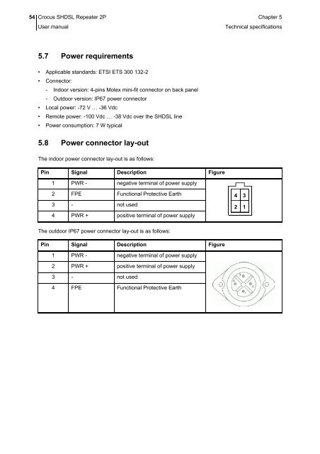
54 Crocus SHDSL Repeater 2P Chapter 5 User manual Technical specifications 5.7 Power requirements • Applicable standards: ETSI ETS 300 132-2 • Connector: - Indoor version: 4-pins Molex mini-fit connector on back panel - Outdoor version: IP67 power connector • Local power: -72 V … -36 Vdc • Remote power: -100 Vdc … -38 Vdc over the SHDSL line • Power consumption: 7 W typical 5.8 Power connector lay-out The indoor power connector lay-out is as follows: Pin Signal Description Figure 1 PWR - negative terminal of power supply 2 FPE Functional Protective Earth 3 - not used 4 PWR + positive terminal of power supply 4 2 3 1 The outdoor IP67 power connector lay-out is as follows: Pin Signal Description Figure 1 PWR - negative terminal of power supply 2 PWR + positive terminal of power supply 3 - not used 4 FPE Functional Protective Earth
Crocus SHDSL Repeater 2P Chapter 5 55 User manual Technical specifications 5.9 Dimensions Dimensions of the indoor Crocus SHDSL Repeater 2P: • Width: 100 mm • Height: 45 mm • Depth: 197 mm • Weight: 0.8 kg Dimensions of the outdoor Crocus SHDSL Repeater 2P: • Width: 360 mm • Depth: 240 mm • Height: 128 mm • Weight: 5 kg 5.10 Safety compliance • EN60950 • Class 3 equipment (Table Top with -48 Vdc internal power supply) 5.11 Over-voltage and over-current protection compliance The over-voltage and over-current protection complies with ITU-T K.44 and ETSI ETS 300 386-2 recommendations. 5.12 EMC compliance • EN55022 B Emissions • EN55024 Immunity • EN61000-3-2 Harmonics • EN61000-3-3 Voltage fluctuations and flicker • EN61000-4-2 ESD • EN61000-4-3 Radiated immunity • EN61000-4-4 EFT/burst • EN61000-4-5 Surge • EN61000-4-6 Conducted immunity • EN61000-4-8 Power magnetic field immunity • EN61000-4-11 Voltage dips & drops • ENV50204 Radiated immunity against digital radio telephone
- Page 11 and 12: Crocus SHDSL Repeater 2P Chapter 1
- Page 13 and 14: Crocus SHDSL Repeater 2P Chapter 1
- Page 15 and 16: Crocus SHDSL Repeater 2P Chapter 1
- Page 17 and 18: Crocus SHDSL Repeater 2P Chapter 2
- Page 19 and 20: Crocus SHDSL Repeater 2P Chapter 2
- Page 21 and 22: Crocus SHDSL Repeater 2P Chapter 2
- Page 23 and 24: Crocus SHDSL Repeater 2P Chapter 2
- Page 25 and 26: Crocus SHDSL Repeater 2P Chapter 2
- Page 27 and 28: Crocus SHDSL Repeater 2P Chapter 2
- Page 29 and 30: Crocus SHDSL Repeater 2P Chapter 2
- Page 31 and 32: Crocus SHDSL Repeater 2P Chapter 2
- Page 33 and 34: Crocus SHDSL Repeater 2P Chapter 2
- Page 35 and 36: Crocus SHDSL Repeater 2P Chapter 2
- Page 37 and 38: Crocus SHDSL Repeater 2P Chapter 3
- Page 39 and 40: Crocus SHDSL Repeater 2P Chapter 3
- Page 41 and 42: Crocus SHDSL Repeater 2P Chapter 3
- Page 43 and 44: Crocus SHDSL Repeater 2P Chapter 3
- Page 45 and 46: Crocus SHDSL Repeater 2P Chapter 4
- Page 47 and 48: Crocus SHDSL Repeater 2P Chapter 4
- Page 49 and 50: Crocus SHDSL Repeater 2P Chapter 4
- Page 51 and 52: Crocus SHDSL Repeater 2P Chapter 4
- Page 53 and 54: Crocus SHDSL Repeater 2P Chapter 4
- Page 55 and 56: Crocus SHDSL Repeater 2P Chapter 5
- Page 57 and 58: Crocus SHDSL Repeater 2P Chapter 5
- Page 59 and 60: Crocus SHDSL Repeater 2P Chapter 5
- Page 61: Crocus SHDSL Repeater 2P Chapter 5
- Page 65 and 66: Crocus SHDSL Repeater 2P 57 Annex A
- Page 67 and 68: Crocus SHDSL Repeater 2P Annex A: 5
- Page 69 and 70: Crocus SHDSL Repeater 2P Annex Inde
54 <strong>Crocus</strong> <strong>SHDSL</strong> <strong>Repeater</strong> <strong>2P</strong> Chapter 5<br />
User manual<br />
Technical specifications<br />
5.7 Power requirements<br />
• Applicable standards: ETSI ETS 300 132-2<br />
• Connector:<br />
- Indoor version: 4-pins Molex mini-fit connector on back panel<br />
- Outdoor version: IP67 power connector<br />
• Local power: -72 V … -36 Vdc<br />
• Remote power: -100 Vdc … -38 Vdc over the <strong>SHDSL</strong> line<br />
• Power consumption: 7 W typical<br />
5.8 Power connector lay-out<br />
The indoor power connector lay-out is as follows:<br />
Pin Signal Description Figure<br />
1 PWR - negative terminal of power supply<br />
2 FPE Functional Protective Earth<br />
3 - not used<br />
4 PWR + positive terminal of power supply<br />
4<br />
2<br />
3<br />
1<br />
The outdoor IP67 power connector lay-out is as follows:<br />
Pin Signal Description Figure<br />
1 PWR - negative terminal of power supply<br />
2 PWR + positive terminal of power supply<br />
3 - not used<br />
4 FPE Functional Protective Earth


