TLE 20 - Logitron
TLE 20 - Logitron
TLE 20 - Logitron

Create successful ePaper yourself
Turn your PDF publications into a flip-book with our unique Google optimized e-Paper software.
<strong>TLE</strong> <strong>20</strong><br />
MICROPROCESSOR-BASED<br />
DIGITAL ELECTRONIC FREEZER<br />
CONTROLLER<br />
OPERATING INSTRUCTIONS<br />
Vr. 01 (ENG) - 09/06 - cod.: ISTR 07<strong>20</strong>5<br />
TECNOLOGIC S.p.A.<br />
INDEX<br />
1 INSTRUMENT DESCRIPTION<br />
1.1 GENERAL DESCRIPTION<br />
1.2 FRONT PANEL DESCRIPTION<br />
2 PROGRAMMING<br />
2.1 PROGRAMMING OF SET POINT<br />
2.2 PARAMETERS PROGRAMMING<br />
2.3 PARAMETER PROTECTION USING THE PASSWORD<br />
2.4 PARAMETERS PROGRAMMING LEVEL<br />
3 INFORMATION ON INSTALLATION AND USE<br />
3.1 PERMITTED USE<br />
3.2 MECHANICAL MOUNTING<br />
3.3 ELECTRICAL CONNECTIONS<br />
3.4 ELECTRICAL WIRING DIAGRAM<br />
4 FUNCTIONS<br />
4.1 ON / STAND-BY FUNCTION<br />
4.2 MEASURING AND VISUALIZATION<br />
4.3 TEMPERATURE CONTROL<br />
4.4 COMPRESSOR PROTECTION FUNCTION AND DELAY<br />
AT POWER-ON<br />
4.5 DEFROST CONTROL<br />
4.6 MANUAL DEFROST<br />
4.7 PARAMETERS CONFIGURATION BY KEY01<br />
5 PROGRAMMABLE PARAMETERS TABLE<br />
6 PROBLEMS , MAINTENANCE AND GUARANTEE<br />
6.1 SIGNALLING<br />
6.2 CLEANING<br />
6.3 GUARANTEE AND REPAIRS<br />
7 TECHNICAL DATA<br />
7.1 ELECTRICAL DATA<br />
7.2 MECHANICAL DATA<br />
7.3 MECHANICAL DIMENSIONS, PANEL CUT-OUT AND<br />
MOUNTING<br />
7.4 FUNCTIONAL DATA<br />
7.5 INSTRUMENT ORDERING CODE<br />
FOREWORD<br />
VIA INDIPENDENZA 56<br />
27029 VIGEVANO (PV) ITALY<br />
TEL.: +39 0381 69871<br />
FAX: +39 0381 698730<br />
internet : http:\\www.tecnologic.it<br />
e-mail: info@tecnologic.it<br />
This manual contains the information<br />
necessary for the product to be installed<br />
correctly and also instructions for its<br />
maintenance and use; we therefore<br />
recommend that the utmost attention is paid to<br />
the following instructions and to save it.<br />
This document is the exclusive property of TECNOLOGIC<br />
S.p.A. which forbids any reproduction and divulgation , even in<br />
part, of the document, unless expressly authorized.<br />
TECNOLOGIC S.p.A. reserves the right to make any formal or<br />
functional changes at any moment and without any notice.<br />
Whenever a failure or a malfunction of the device may cause<br />
dangerous situations for persons, thing or animals, please<br />
remember that the plant has to be equipped with additional<br />
devices which will guarantee safety.<br />
Tecnologic S.p.A. and its legal representatives do not assume<br />
any responsibility for any damage to people, things or animals<br />
deriving from violation, wrong or improper use or in any case<br />
not in compliance with the instrument’s features.<br />
1 - INSTRUMENT DESCRIPTION<br />
1.1 - GENERAL DESCRIPTION<br />
The model <strong>TLE</strong> <strong>20</strong> is a digital controller with microprocessor that is<br />
typically used in cooling applications that have temperature control<br />
with ON/OFF regulation and defrosting control with set time by<br />
means of stopping compressor.<br />
The instrument has one relay output and one input for PTC or NTC<br />
temperature probes.<br />
The instrument is equipped with 3 programme keys, a 2 ½ digit<br />
display and 3 LED signals.<br />
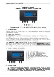
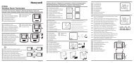
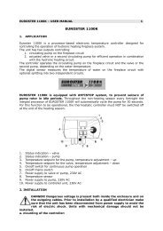
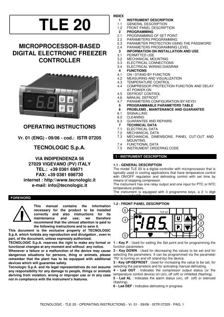
1.2 - FRONT PANEL DESCRIPTION<br />
6<br />
4<br />
5<br />
Out<br />
AL<br />
Def<br />
<strong>TLE</strong> <strong>20</strong><br />
SET<br />
1 - Key P : Used for setting the Set point and for programming the<br />
function parameters<br />
2 - Key DOWN : Used for decreasing the values to be set and for<br />
selecting the parameters. It can be programmed via the parameter<br />
“Fb” to turning on and off (stand-by) the device.<br />
3 - Key UP/DEFROST : Used for increasing the value to be set, for<br />
selecting the parameters and for activating manual defrosting.<br />
4 - Led OUT : Indicates the compressor output status (or the<br />
temperature control device) on (on), off (off) or inhibited (flashing).<br />
5 - Led AL : Indicates the alarm status (on), off (off) or silenced<br />
(flashing).<br />
6 - Led DEF : Indicates defrosting in progress<br />
3<br />
2<br />
1<br />
7<br />
TECNOLOGIC - <strong>TLE</strong> <strong>20</strong> - OPERATING INSTRUCTIONS - Vr. 01 - 09/06 - ISTR 07<strong>20</strong>5 - PAG. 1
7 - Led SET : Indicates the input in programming mode and the<br />
programming level of the parameters. It also serves to indicate the<br />
Stand-by status.<br />
2 - PROGRAMMING<br />
2.1 - PROGRAMMING OF THE SET POINT<br />
Press the key P then release it and the display will show SP<br />
alternating with the set value.<br />
To change it press the UP key to increase the value or DOWN to<br />
decrease it.<br />
These keys increase or decrease the value one digit at a time, but<br />
if the button is pressed for more than one second the value<br />
increase or decreases rapidly, and after two seconds pressed, the<br />
speed increases even more to all the desired valued to be reached<br />
rapidly.<br />
Exiting the Set mode is achieved by pressing the P key or<br />
automatically if no key is pressed for 15 seconds. After that time<br />
the display returns to the normal function mode.<br />
2.2 - PARAMETERS PROGRAMMING<br />
To access the instrument’s function parameters, press the key P<br />
and keep it pressed for about 5 seconds, after which the SET led<br />
will light up, the display will visualised the code that identifies the<br />
first parameter.<br />
Using the UP and DOWN keys, the desired parameter can be<br />
selected and pressing the P key, the display will alternately show<br />
the parameter code and its setting that can be changed with the UP<br />
and DOWN keys.<br />
Once the desired value has been set, press the key P again: the<br />
new value will be memorised and the display will show only the<br />
code of the selected parameter.<br />
Pressing the UP and DOWN keys, it is possible to select another<br />
parameter and change it as described.<br />
To exit the programming mode, do not press any key for about <strong>20</strong><br />
seconds, or keep the UP or DOWN key pressed until it exits the<br />
programming mode.<br />
2.3 - PARAMETER PROTECTION USING THE PASSWORD<br />
The instrument has a parameter protection function using a<br />
password that can be personalised, through the “PP” parameter.<br />
If one wishes to have this protection, set the password number<br />
desired in the parameter “PP”.<br />
When the protection is working, press the P key to access the<br />
parameters and keep it press for about 5 seconds, after which the<br />
LED SET will flash and the display will show “0” .<br />
At this point, using the UP and DOWN keys, set the password<br />
number programmed and press the key "P".<br />
If the password is correct, the display will visualise the code that<br />
identifies the first parameter and it will be possible to programme<br />
the instrument in the same ways described in the previous section.<br />
Protection using a password can be disabled by setting the<br />
parameter “PP” = oF.<br />
2.4 - PARAMETERS PROGRAMMING LEVELS<br />
The instrument has two parameter programming levels.<br />
The first level (“visible” parameters) is accessed according to the<br />
procedure described above (with or without password request)<br />
while the second level (“hidden” password) can be accessed<br />
according to the following procedure.<br />
Remove the power supply to the instrument, press the key P and<br />
return power to the instrument, keeping the key pressed.<br />
After about 5 sec. the display will show the code that identifies the<br />
first parameter and it will be possible to set the parameters of the<br />
instrument using the same programming procedure described<br />
previously.<br />
Once the parameter has been selected and the SET is on, it means<br />
that the parameter can be programmed even on the first level<br />
("visible”).<br />
If the led is off it means that the parameter can only be<br />
programmed on this level (i.e. “hidden”).<br />
To change the visibility of the parameter, press and keep pressed<br />
the key P while acting on UP key: the led SET will change status,<br />
indicating the accessibility level of the parameter (on = parameter<br />
“visible”; off = parameter “hidden”).<br />
The access procedure for “hidden” parameters allows the “PP”<br />
parameter to be checked and changed, and is useful therefore if<br />
the password set has been forgotten.<br />
3 - INFORMATION ON INSTALLATION AND USE<br />
3.1 - PERMITTED USE<br />
The instrument has been projected and<br />
manufactured as a measuring and control device<br />
to be used according to EN60730-1 for the<br />
altitudes operation until <strong>20</strong>00 ms.<br />
The use of the instrument for applications not<br />
expressly permitted by the above mentioned rule must adopt all the<br />
necessary protective measures.<br />
The instrument CANNOT be used in dangerous environments<br />
(flammable or explosive) without adequate protection.<br />
The installer must ensure that EMC rules are respected, also after<br />
the instrument installation, if necessary using proper filters.<br />
Whenever a failure or a malfunction of the device may cause<br />
dangerous situations for persons, thing or animals, please<br />
remember that the plant has to be equipped with additional devices<br />
which will guarantee safety.<br />
3.2 - MECHANICAL MOUNTING<br />
The instrument, in case 33 x 75 mm, is designed for flush-in panel<br />
mounting.<br />
Make a hole 29 x 71 mm and insert the instrument, fixing it with the<br />
provided special brackets.<br />
We recommend that the gasket is mounted in order to obtain the<br />
front protection degree as declared.<br />
Avoid placing the instrument in environments with very high<br />
humidity levels or dirt that may create condensation or introduction<br />
of conductive substances into the instrument.<br />
Ensure adequate ventilation to the instrument and avoid installation<br />
in containers that house devices which may overheat or which may<br />
cause the instrument to function at a higher temperature than the<br />
one permitted and declared.<br />
Connect the instrument as far away as possible from sources of<br />
electromagnetic disturbances such as motors, power relays, relays,<br />
solenoid valves, etc.<br />
3.3 - ELECTRICAL CONNECTION<br />
Carry out the electrical wiring by connecting only one wire to each<br />
terminal, according to the following diagram, checking that the<br />
power supply is the same as that indicated on the instrument and<br />
that the load current absorption is no higher than the maximum<br />
electricity current permitted.<br />
As the instrument is built-in equipment with permanent connection<br />
inside housing, it is not equipped with either switches or internal<br />
devices to protect against overload of current: the installation will<br />
include an overload protection and a two-phase circuit-breaker,<br />
placed as near as possible to the instrument, and located in a<br />
position that can easily be reached by the user and marked as<br />
instrument disconnecting device which interrupts the power supply<br />
to the equipment.<br />
It is also recommended that the supply of all the electrical circuits<br />
connected to the instrument must be protect properly, using<br />
devices (ex. fuses) proportionate to the circulating currents.<br />
It is strongly recommended that cables with proper insulation,<br />
according to the working voltages and temperatures, be used.<br />
Furthermore, the input cable of the probe has to be kept separate<br />
from line voltage wiring. If the input cable of the probe is screened,<br />
it has to be connected to the ground with only one side.<br />
Whether the instrument is 12 V version it’s recommended to use an<br />
external transformer TCTR, or with equivalent features, and to use<br />
only one transformer for each instrument because there is no<br />
insulation between supply and input.<br />
We recommend that a check should be made that the parameters<br />
are those desired and that the application functions correctly before<br />
connecting the outputs to the actuators so as to avoid<br />
TECNOLOGIC - <strong>TLE</strong> <strong>20</strong> - OPERATING INSTRUCTIONS - Vr. 01 - 09/06 - ISTR 07<strong>20</strong>5 - PAG. 2
malfunctioning that may cause irregularities in the plant that could<br />
cause damage to people, things or animals.<br />
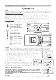
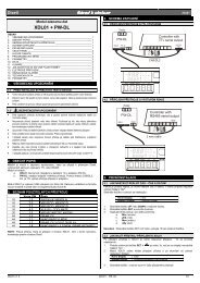
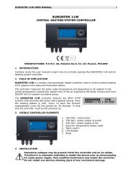
3.4 - ELECTRICAL WIRING DIAGRAM<br />
1 2 3 4<br />
SUPPLY<br />
4 - FUNCTIONS<br />
SPDT 16A-AC1<br />
C<br />
NC<br />
5<br />
OUT<br />
NO<br />
6<br />
INPUT<br />
7 8 9 10 11 12<br />
PTC-NTC<br />
PROBE<br />
4.1 - ON / STAND-BY FUNCTION<br />
The instrument, once powered up, can assume 2 different<br />
conditions:<br />
- ON : means that the controller uses the control functions.<br />
- STAND-BY : means that the controller does not use any control<br />
function and the display is turned off except for the SET led.<br />
If there is no power, and then power returns, the system always<br />
sets itself in the condition it was in before the black-out.<br />
The ON/Stand-by function can be selected using the key DOWN if<br />
parameter "Fb" = 1.<br />
The parameter “Fb” can be configured as follows:<br />
= oF - The key DOWN carries out no function.<br />
= 1 - Pressing the key for at least 1 second, it is possible to switch<br />
the instrument from the ON status to Stand-by status and vice<br />
versa.<br />
4.2- MEASURING AND VISUALIZATION<br />
Via the parameter “SE” it is possible to select the type of probes<br />
that one wishes to use and which can be: thermistores PTC<br />
KTY81-121 (Pt) or NTC 103AT-2 (nt).<br />
Once the type of probe used has been selected, through the<br />
parameter “ru”, it is possible to select the temperature unit of<br />
measurement (°C or °F) and, through the parameter “dP”, the<br />
resolution of the desired measurement (oF=1°; on =0,1°).<br />
The instrument allows the measuring to be calibrated, that can be<br />
used for re-calibrating the instrument according to application<br />
needs, through the parameters “CA”.<br />
Using the parameter “Ft”, it is possible to set the time constant for<br />
the software filter for measuring the input values to be able to<br />
reduce the sensitivity to measurement disturbances (increasing the<br />
time).<br />
Please remember that visualisation of the probe can be changed by<br />
the display block in defrosting function too, by using the parameter<br />
“dL” (see par. 4.5).<br />
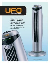
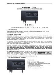
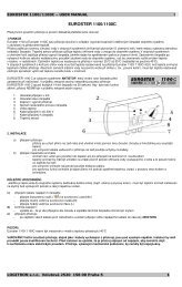
4.3 - TEMPERATURE CONTROL<br />
The regulation of the instrument is ON/OFF and acts on the output<br />
OUT depending on the measuring of probe, of the Set Point “SP”,<br />
the intervention differential “d” and the function mode “HC” .<br />
Depending on the function mode programmed on the parameter<br />
“HC” the differential is automatically considered by the regulator<br />
with positive values for a Refrigeration control (“HC”=C) or with<br />
negative values for a heating control (“HC”=H).<br />
In the event of probe error, it is possible to set the instrument so<br />
that that the output OUT continues to work in cycles according to<br />
the times programmed in the parameter “t1” (activation time) and<br />
“t2” (deactivation time).<br />
If an error occurs on the probe the instrument activates the output<br />
for the time “t1”, then deactivates it for the time “t2” and so on whilst<br />
the error remains.<br />
Programming “t1” = oF the output in probe error condition will<br />
remain switched off.<br />
Programming instead “t1” to any value and “t2” = oF the output in<br />
probe error condition will remain switched on.<br />
Remember that the temperature regulation function can be<br />
conditioned by the “Compressor Protection” function described<br />
below.<br />
Temp.<br />
SP<br />
OUT<br />
ON ON ON<br />
off<br />
HC=C<br />
off<br />
d<br />
time<br />
Temp.<br />
SP<br />
OUT<br />
ON<br />
off<br />
ON<br />
HC=H<br />
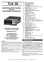
4.4 - COMPRESSOR PROTECTION FUNCTION AND DELAY AT<br />
POWER-ON<br />
The function “Compressor Protection” carried out by the machine<br />
aims to avoid close start ups of the compressor controlled by the<br />
instrument in cooling applications.<br />
This function foresees a time control on the switching on of the<br />
OUT output associated with the temperature regulation request.<br />
The protection consists of preventing the output being switched on<br />
during the time set in the parameter “Pt” and counted depending<br />
on what has been programmed in the parameter “PS”, and<br />
therefore that any activation occurs only after the “Pt” time has<br />
finished.<br />
If during the power on delay phase, the regulator request should<br />
disappear, due to an inhibition caused by the compressor<br />
protection function, the foreseen start up of the output is naturally<br />
cancelled.<br />
Using the parameter “PS", it is possible to set the type of<br />
compressor protection and therefore from when the inhibition time<br />
“Pt” must start.<br />
The parameter “PS” can be set as:<br />
= 1 : Power on delay<br />
T e m p .<br />
S P<br />
O U T<br />
o ff<br />
P t<br />
O N<br />
= 2 : Delay after power off<br />
T e m p .<br />
S P<br />
O U T<br />
O N<br />
"P S " = 1<br />
o ff o ff o ff<br />
o ff<br />
P t<br />
O N<br />
"P S " = 2<br />
O N<br />
= 3 : Delay between power on phases.<br />
T e m p .<br />
S P<br />
O U T<br />
O N<br />
P t<br />
P t<br />
O N<br />
P t P t P t<br />
o ff<br />
o ff<br />
"P S " = 3<br />
O N<br />
P t<br />
o ff<br />
O N<br />
P t<br />
off<br />
o ff<br />
o ff<br />
d<br />
ON<br />
d<br />
time<br />
d<br />
tim e<br />
tim e<br />
d<br />
tim e<br />
The function is disabled by programming “Pt” = 0.<br />
During the power on delay phases of the OUT output by inhibiting<br />
the function “Compressor Protection” the led OUT flashes.<br />
O N<br />
TECNOLOGIC - <strong>TLE</strong> <strong>20</strong> - OPERATING INSTRUCTIONS - Vr. 01 - 09/06 - ISTR 07<strong>20</strong>5 - PAG. 3
It is also possible to prevent activation of the output after the<br />
instrument is turned on, for the time set in the parameter “od”.<br />
The function is disabled by “od” = oF.<br />
During the power on delay phase, the display shows the indication<br />
od, alternating with the normal programmed visualisation.<br />
4.5 - DEFROST CONTROL<br />
The automatic control of defrost, that is by stopping compressor,<br />
occours according to this parameters:<br />
"dC" : Defrost interval computation<br />
- rt - based on real time (instrument on)<br />
- ct - based only on compressor running time (output on)<br />
"di" : Interval between defrost cycles (hrs.)<br />
"dn" : Interval between defrost cycles (min.)<br />
"dE" : Lenght of defrost cycles<br />
The instrument switch off the output for the time “dE” each [“di” +<br />
“dn”] time (of real time functioning if “dC” = rt, or of compressor<br />
running time if “dC” = ct).<br />
SUPPLY<br />
Instrument supplied from the device<br />
SUPPLY ADAPTER<br />
Temp.<br />
OUT<br />
SP<br />
Defrost<br />
ON<br />
(ex. with “dC” = rt)<br />
di + dn<br />
off<br />
ON ON ON<br />
off off off<br />
dE<br />
(DEFROST)<br />
di + dn<br />
The occurring defrost cycle is signalized by the led DEF.<br />
Through par. “dL”,“Et” and “dA” it’s possible to define the display<br />
behaviour during defrost.<br />
The “dL” parameter pemits the display visualization lock on the last<br />
temperature reading (dL = on) during all the defrost cycle until, at<br />
the end of defrost, the temperature has not reached the value [SP +<br />
Et] or is ended the time setted on par. "dA".<br />
Or it permits the visualization of label "dF" (“dL” = Lb) during the<br />
defrost cycle and, after the defrost, of label "Pd" until, at the end of<br />
defrost, the temperature has not reached the value [SP + Et] or is<br />
ended the time setted on par. "dA".<br />
The display will otherwise continue to visualize the temperature<br />
measured by the probe during the defrost cycle (“dL”= oF).<br />
4.6 - MANUAL DEFROST<br />
To start up a manual defrosting cycle, press the key UP/DEFROST<br />
when it is not in programming mode and keep it pressed for about 5<br />
seconds after which, if the conditions are correct, the led DEF will<br />
light up and the instrument will carry out a defrosting cycle.<br />
4.7 - PARAMETERS CONFIGURATION BY “KEY01”<br />
As option the instrument can be equipped with a connector that<br />
allows the transfer from and toward the instrument of the<br />
functioning parameters through the device TECNOLOGIC KEY01<br />
with 5 poles connector.<br />
This device it’s mainly useable for the serial programming of the<br />
instruments which need to have the same parameters configuration<br />
or to keep a copy of the programming of an instrument and allow its<br />
rapid retransmission.<br />
To use the device KEY01 it’s necessary that the device or<br />
instrument are being supplied.<br />
Instrument supplied and device not supplied<br />
dE<br />
d<br />
time<br />
12 VDC AC SUPPLY<br />
For additional info, please have a look at the KEY01 instruction<br />
manual.<br />
5 - PROGRAMMABLE PARAMETERS TABLE<br />
Par. Description Range Def. Note<br />
1 LS Minimum Set Point -58 ÷ HS -50<br />
2 HS Maximum Set Point LS ÷ 199 100<br />
3 SE Probe Type Pt - nt nt<br />
4 CA Probe Calibration -30 ÷ 30 0.0<br />
°C/°F<br />
5 ru Unit of measurement °C - °F °C<br />
6 dP Decimal point on - oF on<br />
7 Ft Measurement filter oF ÷ <strong>20</strong> 2.0<br />
sec<br />
8 d Differential 0 ÷ 30 2.0<br />
°C/°F<br />
9 t1 Activation time output oF ÷ 99 oF<br />
OUT for probe broken<br />
10 t2 Deactivation time<br />
output OUT for probe<br />
broken<br />
min.<br />
oF ÷ 99<br />
min.<br />
11 HC Function mode output<br />
OUT<br />
H - C<br />
12 di Defrosting interval (hrs) oF ÷ 24<br />
hrs<br />
13 dn Defrosting interval (min) oF ÷ 59<br />
min<br />
14 dE Lenght of defrost cycle oF ÷ 99<br />
min<br />
15 dC Defrosting intervals rt - ct<br />
Counting mode:<br />
rt = real time<br />
ct = On OUT time<br />
16 dL Defrost display Lock:<br />
oF= display free<br />
on= Lock on<br />
temperature before<br />
defrost<br />
Lb= Lock on label “dF”<br />
(during defrosting) and<br />
“Pd” (during postdefrosting)<br />
17 Et Differential display<br />
unlock after defrost<br />
18 PS Type of compressor<br />
protection:<br />
1= delay at switch on<br />
2= delay after switch off<br />
3= delay between starts<br />
on - oF - Lb<br />
oF<br />
C<br />
6<br />
oF<br />
30<br />
rt<br />
oF<br />
0 ÷ 30 2.0<br />
°C/°F<br />
1 - 2 - 3 1<br />
TECNOLOGIC - <strong>TLE</strong> <strong>20</strong> - OPERATING INSTRUCTIONS - Vr. 01 - 09/06 - ISTR 07<strong>20</strong>5 - PAG. 4
19 Pt Compressor protection oF ÷ 99 oF<br />
time<br />
min.<br />
<strong>20</strong> od Delay at power on oF ÷ 99 oF<br />
min.<br />
21 dA Unlock display delay oF ÷ 24 1<br />
after defrost<br />
hrs<br />
22 Fb Function mode key oF / 1 oF<br />
DOWN:<br />
oF= No Function<br />
1= ON/STAND-BY<br />
23 PP Access Password to oF ÷ 199 oF<br />
parameter functions<br />
24 SP Set Point LS ÷ HS 0.0<br />
6 - PROBLEMS, MAINTENANCE AND GUARANTEE<br />
6.1 - SIGNALLING<br />
Error Signalling:<br />
Error Reason Action<br />
E1 The probe may be Check the correct<br />
-E1 interrupted or in short<br />
circuit, or may measure a<br />
value outside the range<br />
allowed<br />
connection of the probe<br />
with the instrument and<br />
check the probe works<br />
correctly<br />
EE Internal memory error Check and if necessary<br />
re-programme the<br />
parameters function.<br />
In probe error status, the output OUT behaves as set by the<br />
parameters “t1” and “t2”.<br />
Other Signalling:<br />
Message<br />
Reason<br />
od Delay in switching on in progress<br />
dF Defrosting in progress with “dL”=Lb<br />
Pd Post-defrosting in progress with “dL”=Lb<br />
Protection class : Class II<br />
Insulation: Reinforced insulation between the low voltage part<br />
(supply 115/230 V and relay output) and front panel; Reinforced<br />
insulation between the low voltage section (supply 115/230 V and<br />
relay output) and the extra low voltage section (inputs); Reinforced<br />
between supply and relay output; No insulation between supply 12<br />
V and inputs.<br />
7.2 - MECHANICAL DATA<br />
Housing: Self-extinguishing plastic, UL 94 V0<br />
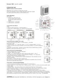
Dimensions: 33 x 75 mm, depth 64 mm<br />
Weight: 150 g approx.<br />
Mounting: Flush in panel in 29 x 71 mm hole<br />
Connections: 2,5 mm 2 screw terminals block<br />
Degree of front panel protection : IP 65 (NEMA 3S) mounted in<br />
panel with gasket<br />
Pollution situation: 2<br />
Operating temperature: 0 T 50 °C<br />
Operating humidity: < 95 RH% without condensation<br />
Storage temperature: -10 T +60 °C<br />
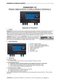
7.3 – MECHANICAL DIMENSIONS, PANEL CUT-OUT AND<br />
MOUNTING [mm]<br />
33<br />
Out<br />
AL<br />
75<br />
Def <strong>TLE</strong> <strong>20</strong><br />
29<br />
SET<br />
71<br />
5<br />
min. 15 mm<br />
64<br />
28<br />
6.2 - CLEANING<br />
We recommend cleaning of the instrument with a slightly wet cloth<br />
using water and not abrasive cleaners or solvents which may<br />
damage the instrument.<br />
6.3 - GUARANTEE AND REPAIRS<br />
The instrument is under warranty against manufacturing flaws or<br />
faulty material, that are found within 12 months from delivery date.<br />
The guarantee is limited to repairs or to the replacement of the<br />
instrument.<br />
The eventual opening of the housing, the violation of the instrument<br />
or the improper use and installation of the product will bring about<br />
the immediate withdrawal of the warranty’s effects.<br />
In the event of a faulty instrument, either within the period of<br />
warranty, or further to its expiry, please contact our sales<br />
department to obtain authorisation for sending the instrument to<br />
our company.<br />
The faulty product must be shipped to TECNOLOGIC with a<br />
detailed description of the faults found, without any fees or charge<br />
for Tecnologic, except in the event of alternative agreements.<br />
7 - TECHNICAL DATA<br />
min. 12 mm<br />
PANEL + GASKET<br />
MAX 12 mm<br />
BRACKETS<br />
RECOMMENDED<br />
PANEL CUTOUT<br />
34<br />
7.1 - ELECTRICAL DATA<br />
Power supply: 12 VAC/VDC, 115 VAC, 230 VAC +/- 10%<br />
Frequency AC: 50/60 Hz<br />
Power consumption: 3 VA approx.<br />
Input/s: 1 input for temperature probes: PTC (KTY 81-121, 990 Ω<br />
@ 25 °C) or NTC (103AT-2, 10KΩ @ 25 °C).<br />
Output/s: 1 relay output SPDT (16A-AC1, 6A-AC3 250 VAC, 1HP<br />
250VAC, 1/2HP 125 VAC).<br />
Electrical life for relay outputs: 50000 op. (om. VDE)<br />
Action type: type 1.B (EN 60730-1)<br />
Overvoltage category: II<br />
7.4 - FUNCTIONAL FEATURES<br />
Temperature Control: ON/OFF mode<br />
Defrost control: interval cycles by stopping compressor<br />
Measurement range: PTC: -50 T 150 °C / -58 T 199 °F;<br />
NTC: -50 T 109 °C / -58 T 199 °F<br />
Display resolution: 1 ° or 0,1° (range -19.9 ...19.9 °)<br />
Overall accuracy: +/- (0,5 % fs + 1 digit)<br />
Sampling rate: 130 ms.<br />
Display:2 ½ Digit Red h 14 mm<br />
TECNOLOGIC - <strong>TLE</strong> <strong>20</strong> - OPERATING INSTRUCTIONS - Vr. 01 - 09/06 - ISTR 07<strong>20</strong>5 - PAG. 5
Software class and structure : Class A<br />
Compliance: ECC directive 89/336 (EN55022: class B; EN61000-4-<br />
2: 8KV air, 4KV cont.; EN61000-4-3: 10V/m; EN61000-4-4: 2KV<br />
supply, inputs, outputs; EN61000-4-5: supply 2KV com. mode, 1<br />
KV\ diff. mode; EN61000-4-6: 3V), <strong>20</strong>06/95/CE (EN 60730-1, EN<br />
60730-2-7, EN 60730-2-9)<br />
7.5 - INSTRUMENT ORDERING CODE<br />
<strong>TLE</strong><strong>20</strong> DS- = 230 VAC without KEY01 conn.<br />
<strong>TLE</strong><strong>20</strong> DSK = 230 VAC with KEY01 conn.<br />
<strong>TLE</strong><strong>20</strong> CS- = 115 VAC without KEY01 conn.<br />
<strong>TLE</strong><strong>20</strong> CSK = 115 VAC with KEY01 conn.<br />
<strong>TLE</strong><strong>20</strong> FS- = 12 VAC/VDC without KEY01 conn.<br />
<strong>TLE</strong><strong>20</strong> FSK = 12 VAC/VDC with KEY01 conn.<br />
TECNOLOGIC - <strong>TLE</strong> <strong>20</strong> - OPERATING INSTRUCTIONS - Vr. 01 - 09/06 - ISTR 07<strong>20</strong>5 - PAG. 6