SigNET 100200300 User Guide - Lockmates
SigNET 100200300 User Guide - Lockmates
SigNET 100200300 User Guide - Lockmates

You also want an ePaper? Increase the reach of your titles
YUMPU automatically turns print PDFs into web optimized ePapers that Google loves.
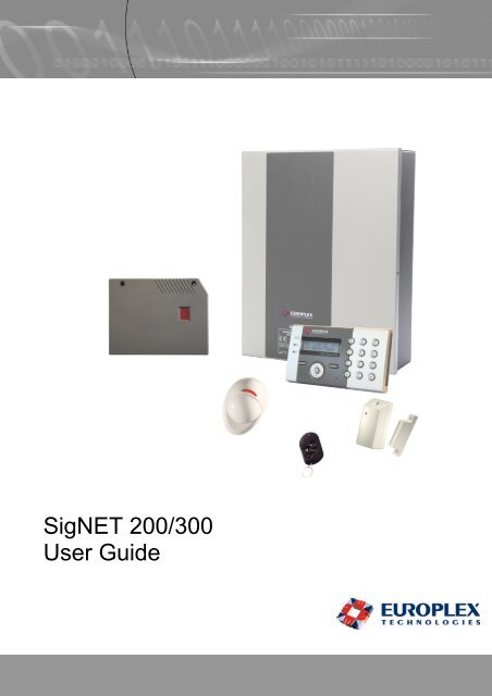
<strong>SigNET</strong> 200/300<br />
<strong>User</strong> <strong>Guide</strong>
Warning: While this system is an advanced design integrated security system, it does not offer guaranteed protection against<br />
burglary, fire or other emergency. Any alarm system, whether commercial or domestic, is subject to compromise or failure to<br />
warn for a variety of reasons.<br />
Therefore, good installation practices, thorough testing, and regular maintenance by the installation company and frequent<br />
testing by the user are essential to ensure continuous satisfactory operation of the system. It is recommended that the<br />
installation company offer a maintenance program and instruct the user with the correct procedure for use and testing of the<br />
system.<br />
COPYRIGHT NOTICE<br />
Copyright © 2006 Europlex Technologies Ltd (hereby referred to as Europlex). All rights reserved. No part of this<br />
publication may be reproduced, transmitted, stored in a retrieval system, or translated into any language or computer<br />
language in any form or by any means electronic, mechanical, magnetic, optical, chemical, manual, or otherwise without<br />
the prior written permission of Europlex.<br />
Disclaimer: Europlex make no representations or warranties with respect to the contents hereof and specifically disclaim<br />
any implied warranties of merchantability or fitness for any particular purpose. Further Europlex reserve the right to revise<br />
this publication and to make changes from time to time in the contents hereof without the obligation of Europlex to notify<br />
any person of any such revision.<br />
All products or services mentioned in this manual are covered by the trademarks, service marks, or product names as<br />
designated by the companies who market those products.<br />
E-LAB-1543 <strong>SigNET</strong> 200/300 <strong>User</strong> <strong>Guide</strong>, Issue 01, Sept 2006<br />
When changing or installing a expanders on the <strong>SigNET</strong> 200/300 system always ensure that<br />
all anti-static precautions are adhered to while handling connectors, wires, terminals and<br />
PCB’s.<br />
Europlex Technologies [IRL] Ltd.<br />
Clonshaugh Business and Technology Park,<br />
Clonshaugh,<br />
Dublin 17,<br />
Ireland.<br />
Tel: +353 (0) 1 2500500<br />
Fax: +353 (0) 1 2500592<br />
Europlex Technologies (UK) Limited<br />
Innovation Centre,<br />
Cranfield University Technology Park,<br />
University Way, Cranfield,<br />
Bedfordshire, MK43 0BT,<br />
United Kingdom.<br />
Tel. +44 (0) 8700 600 140<br />
Fax. +44 (0) 8453 307 240<br />
E-Mail: sales@europlex.ie<br />
Company Web Site address: www.europlex.ie<br />
Technical Support: tech@europlex.ie<br />
Page 2
Table of contents<br />
1. Introducing the <strong>SigNET</strong> 200/300 System ...................................................4<br />
2. How to use your Keypad ............................................................................4<br />
2.1 How to use the Keypad programming interface......................................................................................5<br />
2.2 Data entry on the <strong>SigNET</strong> Keypad..........................................................................................................6<br />
3. Intruder alarm Operation ............................................................................7<br />
3.1 Entering <strong>User</strong> Programming ...................................................................................................................9<br />
3.2 Setting the System -FULLSET................................................................................................................9<br />
3.3 Setting the System – PARTSET A..........................................................................................................9<br />
3.4 Setting the System – PARTSET B..........................................................................................................9<br />
3.5 Unsetting the System............................................................................................................................10<br />
3.6 Fail to set...............................................................................................................................................10<br />
3.7 Force Setting the System......................................................................................................................10<br />
3.8 Inhibiting a Zone....................................................................................................................................11<br />
3.9 Restoring an alert..................................................................................................................................11<br />
3.10 Isolating a Zone or fault ........................................................................................................................12<br />
3.11 Setting the Time and Date ....................................................................................................................12<br />
3.12 Performing Tests on the system ...........................................................................................................13<br />
3.13 Viewing the Event Log ..........................................................................................................................13<br />
3.14 Allowing Engineer Access.....................................................................................................................13<br />
Page 3
1. Introducing the <strong>SigNET</strong> 200/300 System<br />
The <strong>SigNET</strong> 200/300 system must be installed by a qualified installation engineer. When the installation of the<br />
<strong>SigNET</strong> 200/300 has been completed, the engineer will provide you with a user password that will enable you<br />
to SET/UNSET and configure your system as required.<br />
2. How to use your Keypad<br />
The <strong>SigNET</strong> Keypad is a wall mounted programming interface unit that allows you to enter <strong>User</strong> programming<br />
menus (password protected), and perform operational procedures (arm/disarm) on the system. The keypad<br />
unit includes an integral front tamper switch and a 2 line x 16 character display. Three LED’s provide<br />
information on AC power, system alerts and communications status. The Keypad features an easy to use<br />
Navigation key (Navi-Key) to assist you in locating your required programming options and two context<br />
sensitive soft keys (left and right) allowing you to select the required menu or program setting.<br />
The <strong>SigNET</strong> Keypad may be factory fitted with a Portable ACE (PACE) proximity device reader and/or a<br />
wireless module for the enrolment of wireless sensors.<br />
AC Mains LED<br />
System Alert LED<br />
Comms LED<br />
Portable ACE<br />
receiver area<br />
01 Dec 06 17:00<br />
12 x Alphanumeric<br />
Keys for numeric<br />
and text data<br />
entry.<br />
Programming keys<br />
1 x Navi-Key (Multi-functional<br />
navigation key)<br />
2 x context sensitive programming<br />
keys (Left & Right)<br />
Licence Details<br />
Installer Contact Number<br />
Installer Name<br />
Installation Date<br />
Pull down Information<br />
Tab.<br />
The installer contact and<br />
licence details are<br />
available by pulling down<br />
the information tab<br />
LED Status Indicators<br />
AC Mains LED<br />
(Green)<br />
System Alert<br />
(Yellow)<br />
Comms LED<br />
(red)<br />
This LED Indicates the presence, or failure of, the mains supply.<br />
LED FLASHING - AC Mains fault detected. LED STEADY – AC Mains OK<br />
This LED Indicates the occurrence of a system alert. When flashing, a text message on<br />
the display will indicate the location and nature of the alert. If the system is SET, then NO<br />
indication will be given of system alerts.<br />
LED FLASHING - System Alert detected. LED OFF – No Alert detected<br />
This LED Indicates the status of the EBUS communications when in FULL ENGINEER<br />
programming.<br />
Page 4
2.1 How to use the Keypad programming interface<br />
TOP LINE OF DISPLAY<br />
During the IDLE state this line will show the current<br />
date and time.<br />
During Programming mode this line will show one of<br />
the following:<br />
The programming feature to be selected<br />
The current setting of the selected feature<br />
BOTTOM LINE OF DISPLAY<br />
During the IDLE state this line will be blank.<br />
During Programming mode this line will show the 2<br />
options available to the user/Engineer. These<br />
options will be aligned over the left and right soft<br />
keys for selection as required.<br />
During an alert condition this line will show<br />
The nature of the current alert<br />
LEFT SOFT KEY<br />
This key is used to select the<br />
option presented on the left side of<br />
the bottom line of the display.<br />
Possible values are:<br />
- EXIT to exit programming<br />
- BACK to go back to the<br />
previous menu<br />
RIGHT SOFT KEY<br />
This key is used to select the<br />
option presented on the right side<br />
of the bottom line of the display.<br />
Possible values are:<br />
- SELECT to select the menu<br />
displayed on the top line<br />
- ENTER to enter the data<br />
displayed on the top line<br />
- SAVE to save a setting<br />
MULTI-FUNCTION NAVIGATION KEY (NAVI-KEY)<br />
OK - The OK button serves as a SELECT key for the menu option that is displayed on the top line of the<br />
display and also as an ENTER/SAVE key for data that is displayed on the top line of the display.<br />
- In programming mode, the right arrow key will advance the user through the menus in the same way as<br />
pressing the SELECT option ( right soft key). When no more menu options can be selected, this key has<br />
no function. In data entry mode, this key will advance the cursor one position to the right.<br />
- In programming mode, the left arrow key will return the user to the previous menu level. Pressing this<br />
key while in the top menu level will exit the user from programming. In data entry mode, this key will<br />
move the cursor one position to the left.<br />
- In programming mode, the Up arrow key will move the user to the previous programming option in the<br />
same menu level. Continually pressing this key will scroll through all of the programming options<br />
available on the current menu level. In Text entry mode, pressing this key over a lower case character<br />
will change the character to upper case.<br />
- In programming mode, the down arrow key will move the user to the next programming option in the<br />
same menu level. Continually pressing this key will scroll through all of the programming options<br />
available on the current menu level. In Text entry mode, pressing this key over an upper case character<br />
will change the character to lower case.<br />
Page 5
2.2 Data entry on the <strong>SigNET</strong> Keypad<br />
Entering data and navigating the menus on the Signet Keypad is facilitated through the use of the<br />
programming interface. The use of the interface for each type of operation is detailed below.<br />
2.2.1 Entering Numeric values<br />
In Numeric Input mode, you can only enter numeric<br />
digits (0 – 9) . This type of<br />
Pressing the Left & Right arrow keys move the position<br />
of the cursor one character to the left and right<br />
respectively. To exit from the feature without saving<br />
press the BACK menu key.<br />
To save the programmed setting press the ENTER<br />
menu key or the OK key.<br />
2.2.2 Entering Text<br />
In Text Input mode, you can enter alphabetic characters<br />
(A-Z) or numeric digits (0 – 9). To enter an alphabetic<br />
character simply press the relevant key the required<br />
number of times. To enter a digit , hold the relevant key<br />
down for 2 seconds and release.<br />
By pressing the Left and Right arrow keys you can<br />
move the position of the cursor one character to the left<br />
and right respectively. To change the case of an<br />
alphabetic character, simply press the up or down arrow<br />
keys when the character is highlighted by the cursor.<br />
To exit from the feature without saving press the BACK<br />
menu key.<br />
To save the programmed setting press the ENTER<br />
menu key or the OK key.<br />
Pressing the hash (#) key toggles between upper and<br />
lower case character entry for all subsequent characters.<br />
Press the star key(*) to delete character to the left of the<br />
cursor.<br />
2.2.3 Selecting a programming option<br />
In navigation mode, the Engineer/<strong>User</strong> simply selects<br />
one of a number of pre-defined programming options<br />
from a list. Pressing the Up & Down arrow keys scrolls<br />
through the list of options available for selection. To exit<br />
from the feature without saving press the BACK menu<br />
key.<br />
To save the selected option press the SAVE menu key<br />
or the OK key.<br />
Note<br />
If X-10 has been set up on your system by the installation engineer, then an X10 device may be<br />
activated by pressing the hash (#) key followed by the device number.<br />
Page 6
3. Intruder alarm Operation<br />
The operational features of the <strong>SigNET</strong> 200/300 system are described below. Your installation engineer will<br />
inform you of the user rights that have been assigned to your user profile. The settings that relate to the<br />
operation of these features are accessible from engineer programming (Default code 1111).<br />
Operation<br />
UNSET<br />
Description<br />
The Unset operation unsets the alarm. This menu option will only be presented on the<br />
keypad after an alarm has been activated and a valid user code has been entered.<br />
RESTORE<br />
FULLSET<br />
FORCESET<br />
PARTSET A<br />
PARTSET B<br />
The restore operation will restore an alert condition on the system and clear the alert<br />
message associated with that alert condition. An alert condition can only be restored<br />
after the zone(s) or fault(s) that triggered the alert condition have been restored to<br />
their normal operating state and the RESTORE option in user programming is<br />
selected for that zone.<br />
The fullset operation fully sets the alarm system and provides full protection to a<br />
building (opening of any alarm zones will activate the alarm).<br />
On selecting Fullset, the buzzer will sound and the keypad display will count down the<br />
Exit time period. Please exit the building before this time period has expired. When<br />
the exit time period has expired the system is set and opening of Entry/Exit zones will<br />
start the Entry timer. If the system is not Unset before the Entry timer expires then<br />
the alarm is activated.<br />
The forceset option is presented on the Keypad display when you attempt to set the<br />
system while an alarm zone is faulty or still open. (The top line of the display will<br />
show the open zone). Selecting this option will set the alarm and inhibit the zone for<br />
that set period.<br />
This mode provides perimeter protection to a building while allowing free movement<br />
through the exit and access areas.<br />
Zones which have been classified as EXCLUDE A will remain unprotected in this<br />
mode. By default there is no exit time - the system sets instantly on selection of this<br />
mode. An exit timer can be applied to this mode by enabling the Partset A Timed<br />
variable.<br />
This setting mode applies protection to all zones except those, which have been<br />
classified as EXCLUDE B.<br />
By default there is no exit time, with the system setting instantly on selection of this<br />
mode. An exit timer can be applied to this mode by enabling the Partset A Timed<br />
variable.<br />
Page 7
Menus<br />
INHIBIT<br />
ISOLATE<br />
SET DATE /<br />
TIME<br />
TEST<br />
EVENT LOG<br />
CHIME<br />
CHANGE<br />
CODE<br />
SETUP SMS<br />
GRANT<br />
ACCESS<br />
These Menu options are only available to Standard or Manager Type <strong>User</strong>s.<br />
Inhibiting a zone will de-activate that zone for one alarm set period. Only Alarm,<br />
Entry/exit, Fire exit and Line zone types can be inhibited.<br />
This is the preferred method of de-activating a faulty or open zone as the fault or<br />
open condition will be displayed on the keypad each time the system is being set to<br />
remind the user to attend to that zone.<br />
Isolating a zone will de-activate that zone until such time as the zone is De-isolated<br />
again. All zone types on the <strong>SigNET</strong> 200/300 can be isolated.<br />
Use of this feature to de-activate faulty or open zones should be considered carefully,<br />
as once a zone is isolated, it will be ignored by the system and may very well be<br />
overlooked completely when setting your system, thus compromising the security of<br />
your building or premises.<br />
This menu option allows you to program the time and date on the system. Please<br />
ensure that the time and date information is accurate as these fields are presented in<br />
the event log when reporting system events.<br />
This menu option provides you the following test features.<br />
1. Bell test<br />
The Bell test will activate the external bells, the strobe, the internal bells and the<br />
buzzer in turn for 5 seconds approximately to ensure their correct operation.<br />
2. Walk Test<br />
A walk test allows you to test the operation of all of the alarm sensors on your<br />
system. On selecting this option, the keypad presents the number of zones to test on<br />
the system. Simply activate each alarm sensor (by opening the door or window) and<br />
check for an audible beep at the Keypad. Isolated and inhibited zones are not<br />
included in the walk test.<br />
3. Audible Options<br />
This option allows you to select which devices will activate during the walk test and<br />
which will be silent.<br />
This menu option will display the most recent event on the keypad display. The event<br />
log will detail the time and date for each logged event.<br />
All zones that have the CHIME attribute set will generate a short burst of audible tone<br />
on the keypad buzzer when they are opened ( while the system is unset).<br />
This menu option allows you to enable or disable the chime feature on all zones.<br />
This menu option allows you to change your user code.<br />
This feature allows you to setup the SMS messaging service if you have a modem<br />
installed on your system. Please consult your installation engineer when<br />
programming this option.<br />
This option allows you to grant access to manufacturer and engineer programming.<br />
Page 8
3.1 Entering <strong>User</strong> Programming<br />
To access user programming simply enter the user code given to<br />
you by the installation engineer on the keypad. As digits are being<br />
entered they will be displayed as asterixes on the LCD and the left<br />
function key will present the option QUIT.<br />
****<br />
QUIT<br />
Press the QUIT key to abort user programming and return to normal<br />
operation mode.<br />
3.2 Setting the System -FULLSET<br />
On entering a Valid <strong>User</strong> Code the user will be presented with the<br />
FULLSET option. The FULLSET operation is used to perform a<br />
complete arming of the system.<br />
The FULLSET option provides the following functionality<br />
- Full protection to a building (opening of alarm zones will<br />
activate the alarm)<br />
- opening of Entry/Exit zones will start the Entry timer. If the<br />
alarm is not Unset before the Entry timer expires then the<br />
alarm is activated.<br />
As soon as the user selects the FULLSET option the second line of<br />
the display will countdown the exit timer and the buzzer will sound<br />
to indicate that the user should exit the building. When the system<br />
has been fully set the LCD will display FULLSET on the bottom line<br />
for approximately 10 seconds.<br />
3.3 Setting the System – PARTSET A<br />
The PARTSET A option provides the following functionality<br />
- Perimeter protection to a building while allowing free<br />
movement through the exit and access areas.<br />
- Zones which have been classified as EXCLUDE A remain<br />
unprotected in this mode<br />
- By default there are no Exit times associated with PARTSET A<br />
and the alarm is activated instantly on selection of this mode.<br />
To select PARTSET A, enter user programming, scroll down to the<br />
PARTSET A option and press SELECT.<br />
3.4 Setting the System – PARTSET B<br />
The PARTSET B option provides the following functionality<br />
- Perimeter protection to a building while allowing free<br />
movement through the exit and access areas.<br />
- Zones which have been classified as EXCLUDE B remain<br />
unprotected in this mode.<br />
- By default there are no Exit times associated with PARTSET B<br />
and the alarm is activated instantly on selection of this mode.<br />
OK<br />
FULL SET<br />
EXIT SELECT<br />
01 SEP 06 17:00<br />
SETTING 45 SECS<br />
01 SEP 06 17:00<br />
FULLSET<br />
PARTSET A?<br />
EXIT SELECT<br />
01 SEP 06 17:00<br />
PARTSET A<br />
PARTSET B?<br />
EXIT SELECT<br />
01 SEP 06 17:00<br />
PARTSET B<br />
Note<br />
Partset A and Partset B modes can be configured to use the Exit timer by enabling the PARTSET<br />
TIMED Variables in Engineer Programming .<br />
Page 9
3.5 Unsetting the System<br />
To UNSET an armed system enter your user code on the keypad.<br />
The Keypad display will prompt the user to unset the system. To<br />
Unset the system press the SELECT key.<br />
UNSET?<br />
EXIT<br />
SELECT<br />
The keypad display will indicate that the system is unset on the<br />
bottom line of the display for approximately 5 seconds. After this<br />
time has elapsed the bottom line will be cleared.<br />
01 SEP 06 17:00<br />
UNSET<br />
If the alarm has been activated, then on entering your user<br />
code all active bells and strobes will be turned off and the<br />
message – PANEL DISARMED – will be displayed on the<br />
keypad for approximately 5 seconds.<br />
The source of the alarm condition will then be displayed on<br />
the keypad and the Alert LED will flash. The keypad will<br />
continue to display the alert until you restore the alert.<br />
(See 3.9 - Restoring an alert).<br />
PANEL DISARMED<br />
ALARM ZONE 2<br />
FIRST ZONE<br />
3.6 Fail to set<br />
The user will fail to set the system if an open or fault<br />
condition is detected on any of the alarm zones when<br />
selecting the FULLSET or PARTSET A/B options. The<br />
Keypad Display will indicate this by flashing the text<br />
FAILED TO SET on the top line of the display followed by<br />
the Zone number and description.<br />
FAILED TO SET<br />
To allow setting of the system, locate the zone and close<br />
or fix the fault. Repeat the FULLSET or PARTSET<br />
operation.<br />
ZONE 3<br />
KITCHEN<br />
3.7 Force Setting the System<br />
If the user has the rights to perform a FORCE SET then<br />
the system can be forced to set while an alarm zone is still<br />
open. This operation will simply inhibit the open zone and<br />
set the system as normal.<br />
If the user has the right to Force set the system and an<br />
alarm zone is open, then on selecting a FULLSET or<br />
PARTSET option, the keypad buzzer will beep and the first<br />
line of the display will indicate the open zone. The user will<br />
be presented with the options to QUIT or FORCE.<br />
ZONE X OPEN<br />
QUIT FORCE<br />
FORCED SET?<br />
BACK SELECT<br />
QUIT - Selecting this key will abort the attempt to set<br />
the system and return the user to user<br />
programming.<br />
FORCE - Selecting this option will inhibit the open zone<br />
and force the system to set.<br />
Check with your installation engineer if you have been given the ability to force set the system.<br />
Note<br />
Page 10
3.8 Inhibiting a Zone<br />
The user has the option to manually inhibit a Zone on the system<br />
from the keypad. The Inhibit operation is active for only one alarm<br />
set period.<br />
• Enter your <strong>User</strong> programming code on the keypad, scroll down<br />
to the MENUS option and press SELECT.<br />
• The INHIBIT option will be displayed on the Keypad. Press the<br />
SELECT key.<br />
• Scroll down to the ZONES menu option and press SELECT.<br />
• A list of zones on the system will be displayed. Select the<br />
required zone and toggle the setting from NOT INHIBITED to<br />
INHIBITED using the up/down arrow keys.<br />
• Press the SELECT key and exit user programming.<br />
MENUS<br />
EXIT<br />
INHIBIT<br />
EXIT<br />
ZONES<br />
BACK<br />
ZONE 1<br />
BACK<br />
SELECT<br />
SELECT<br />
SELECT<br />
SELECT<br />
INHIBITED<br />
BACK SELECT<br />
Note<br />
Only the Alarm, Exit/Entry, Fire exit and Line Zone types can be inhibited on the<br />
<strong>SigNET</strong> system. All other zone types will not be displayed in the inhibit menus.<br />
3.9 Restoring an alert<br />
Alert conditions on the <strong>SigNET</strong> 200/300 are indicated on the<br />
keypad by a flashing yellow Alert LED ( See 2 - How to use your<br />
Keypad ) and by activation of the buzzer. Text on the keypad<br />
display will indicate the location and nature of the alert condition.<br />
ALARM ZONE 2<br />
Sitting Room<br />
The ability of a user to restore alerts on the <strong>SigNET</strong> 200/300<br />
system is programmed by your installation engineer. To restore an<br />
alert condition that is triggered by a zone opening, locate the open<br />
zone ( displayed on the keypad display) and restore the alarm<br />
sensor to it’s normal state (Close the door or window).<br />
At the keypad enter your user code and select the RESTORE<br />
menu option. The zone that caused the alert will be displayed on<br />
the top line of the display. Press the right menu key to restore the<br />
alert. The message - ALL ALERTS RESTORED - will be displayed<br />
and the flashing Alert LED will turn off.<br />
For system or communications type alert conditions (Mains failure<br />
or EBUS disconnect), locate the source of the alert condition and<br />
check that all wires and cables are properly connected. For a<br />
tamper alert, ensure that the lids on all enclosures and devices are<br />
correctly closed. If you cannot restore the physical fault to it’s<br />
normal operating state please contact your installation engineer.<br />
You may still continue to operate your alarm system by either<br />
inhibiting or isolating the fault condition.<br />
RESTORE<br />
EXIT<br />
Sitting Room<br />
QUIT<br />
ALL ALERTS<br />
RESTORED<br />
SELECT<br />
RESTORE<br />
Page 11
3.10 Isolating a Zone or fault<br />
The user has the option to manually isolate a zone or fault on the<br />
system from the keypad. Isolating a zone will remove that zone<br />
from the system until such time as the user de-isolates it. To<br />
isolate a zone:<br />
• Enter your <strong>User</strong> programming code on the keypad, scroll<br />
down to the MENUS option and press SELECT.<br />
• Scroll down to the ISOLATE option using the up&down<br />
arrow keys.<br />
• Press the SELECT key.<br />
• Scroll down to the ZONES menu option and press<br />
SELECT.<br />
• A list of zones on the system will be displayed. Select the<br />
required zone and toggle the setting from NOT ISOLATED<br />
to ISOLATED using the up/down arrow keys.<br />
• Press the SELECT key and exit user programming.<br />
3.11 Setting the Time and Date<br />
The user has the option to manually enter the date and time on<br />
the system. The time and date information is displayed on the<br />
keypad and browser and is used on the time related<br />
programming features.<br />
To program the Date and Time:<br />
MENUS<br />
EXIT<br />
ISOLATE<br />
EXIT<br />
ZONES<br />
BACK<br />
ZONE 1<br />
BACK<br />
SELECT<br />
SELECT<br />
SELECT<br />
SELECT<br />
ISOLATED<br />
BACK SELECT<br />
MENUS<br />
EXIT<br />
SELECT<br />
• Enter your <strong>User</strong> programming code on the keypad, scroll<br />
down to the MENUS option and press SELECT.<br />
• Scroll down to the SET DATE/TIME option using the<br />
up&down arrow keys.<br />
• Press the SELECT key.<br />
• The date will be displayed on the top line of the display. To<br />
enter a new date simply press the required numeric keys<br />
on the keypad. To move the cursor to the left and right<br />
press the left and right arrow keys. On editing the date as<br />
required press the ENTER key to save. If an attempt is<br />
made to save an invalid date value, the text INVALID<br />
VALUE is displayed for 1 second and the user is prompted<br />
to enter a Valid date.<br />
• The time will be displayed in 24hour format on the top line<br />
of the display. To enter a new time press the required<br />
numeric keys on the keypad. To move the cursor to the left<br />
and right press the left and right arrow keys. On editing the<br />
time as required press the ENTER key to save. If an<br />
attempt is made to save an invalid time value, the text<br />
INVALID VALUE is displayed for 1 second and the user is<br />
prompted to enter a Valid time.<br />
SET DATE/TIME<br />
EXIT SELECT<br />
DATE 01/09/2006<br />
BACK ENTER<br />
TIME 11:12:35<br />
BACK ENTER<br />
Page 12
3.12 Performing Tests on the system<br />
The user has the option to perform simple tests on the system to<br />
determine if the bells, buzzers and other audible devices are<br />
operating correctly.<br />
To perform a test on the system:<br />
• Enter your <strong>User</strong> programming code on the keypad, scroll<br />
down to the MENUS option and press SELECT.<br />
• Scroll down to the TEST option using the up&down arrow<br />
keys and press the SELECT key.<br />
• The <strong>User</strong> will be presented with the option to select a<br />
BELL TEST, WALK TEST or test the AUDIBLE OPTIONS.<br />
• On selecting BELL TEST, the user will be presented with<br />
the options - external bells, strobe, internal bells and<br />
Buzzer. On selecting these options each one will sound in<br />
turn to verify that the device is operating correctly.<br />
• On Selecting WALK TEST, the user can test the operation<br />
of each alarm device by activating the device and checking<br />
to hear if an audible beep is given at the keypad.<br />
•<br />
3.13 Viewing the Event Log<br />
The user can view a list of the most recent events on the<br />
system by selecting the event log option. The most recent<br />
event will be displayed on the bottom line of the display with all<br />
previous events displayed for 1 second in turn.<br />
To view the event log on the keypad:<br />
• Enter your <strong>User</strong> programming code on the keypad, scroll<br />
down to the MENUS option and press SELECT.<br />
• Scroll down to the EVENT LOG option using the up/down<br />
arrow keys and press the SELECT key.<br />
• The Keypad display will show the most recent event<br />
logged on the system on the bottom line with all previous<br />
events lashed for a 1 second period in turn.<br />
• To view an event from a particular date, enter the date on<br />
the numeric keys.<br />
•<br />
3.14 Allowing Engineer Access<br />
A user can allow an engineer to access to the system. This<br />
access will be permitted for the Engineer Access time defined<br />
in the system timers menu.<br />
When Engineer access has been allowed by the user the<br />
keypad display will display the text ENGINEER ENABLED on<br />
the top line of the display.<br />
• Enter your <strong>User</strong> programming code on the keypad, scroll<br />
down to the MENUS option and press SELECT.<br />
• Scroll down to the GRANT ACCESS option using the<br />
up/down arrow keys and press the SELECT key.<br />
• Select the ALLOW ENGINEER option and select<br />
ENABLED.<br />
MENUS<br />
EXIT<br />
TEST<br />
EXIT<br />
SELECT<br />
SELECT<br />
BELL TEST<br />
BACK ENTER<br />
EXT BELLS<br />
BACK NEXT<br />
MENUS<br />
EXIT<br />
EVENT LOG<br />
EXIT SELECT<br />
01 SEP 06 17:00<br />
INHIBIT: ZONE 3<br />
MENUS<br />
EXIT<br />
SELECT<br />
SELECT<br />
GRANT ACCESS<br />
EXIT SELECT<br />
ALLOW ENGINEER<br />
BACK SELECT<br />
Page 13
Page 14