THREE STAGE LIGHT OIL BURNERS - riello
THREE STAGE LIGHT OIL BURNERS - riello
THREE STAGE LIGHT OIL BURNERS - riello

Create successful ePaper yourself
Turn your PDF publications into a flip-book with our unique Google optimized e-Paper software.
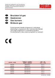
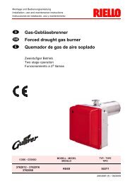
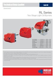
<strong>THREE</strong> <strong>STAGE</strong> <strong>LIGHT</strong> <strong>OIL</strong> <strong>BURNERS</strong><br />
PRESS T/G SERIES P 140 T/G 380/830 ÷ 1660 kW<br />
P 200 T/G 557/1186 ÷ 2372 kW<br />
P 300 T/G 712/1779 ÷ 3560 kW<br />
P 450 T/G 890/2670 ÷ 5340 kW<br />
The PRESS T/G series of burners covers a firing range from 830 to 5340 kW.<br />
Available in 4 different models, this burners are particularly well suited for matching with<br />
pressurized chamber boilers.<br />
For their characteristics, they find application in big civil plants for domestic heating or in<br />
industrial applications where thermal load is repetitive and predictable.<br />
An hydraulic ram exclusive system, with 3 adjustable positions, regulates dampers opening,<br />
allowing air passage in relation to output required: in this way flame stability is optimized<br />
in every working point, with micro-regulation available.<br />
The burners are fitted with a microprocessor control panel which supplies indication of<br />
operation and diagnosis of fault cause.<br />
TS0038UK03
TECHNICAL DATA<br />
Model<br />
P 140 T/G<br />
P 200 T/G<br />
P 300 T/G<br />
P 450 T/G<br />
Burner operation mode<br />
Three stage<br />
Modulation ratio at max. output<br />
3 : 1<br />
Servomotor<br />
run time<br />
type<br />
s<br />
--<br />
--<br />
kW<br />
380/830÷1660<br />
557/1186÷2372<br />
712/1779÷3560<br />
890/2670÷5340<br />
Heat output<br />
Mcal/h<br />
327/714÷1428<br />
479/1020÷2040<br />
612/1530÷3062<br />
765/2296÷4592<br />
kg/h<br />
32/70÷140<br />
47/100÷200<br />
60/150÷300<br />
75/225÷450<br />
Working temperature<br />
°C min./max.<br />
0/40<br />
Net calorific value<br />
kWh/kg<br />
kcal/kg<br />
11,86<br />
10200<br />
Viscosity<br />
mm 2 /s (cSt)<br />
4 ÷ 6 (at 20°C)<br />
Fuel / air data<br />
Pump<br />
delivery<br />
Atomised pressure<br />
Fuel temperature<br />
Fuel pre-heater<br />
type<br />
kg/h<br />
bar<br />
max. °C<br />
J7<br />
190 (20 bar)<br />
J7<br />
190 (20 bar)<br />
12<br />
50<br />
NO<br />
TA2<br />
340 (20 bar)<br />
TA3<br />
525 (20 bar)<br />
Fan<br />
type<br />
Centrifugal with forward curve blades<br />
Air temperature<br />
max. °C<br />
60<br />
Electrical supply<br />
Ph/Hz/V<br />
3N/50/400~(±10%) 3/50/230~(±10%)<br />
Auxiliary electrical supply<br />
Ph/Hz/V<br />
1/50/230 (±10%)<br />
Control box<br />
type<br />
RMO<br />
Total electrical power<br />
kW<br />
4,5<br />
5,5<br />
10<br />
18<br />
Auxiliary electrical power<br />
kW<br />
1,5<br />
1,5<br />
2,5<br />
3<br />
Heaters electrical power<br />
kW<br />
--<br />
Protection level<br />
IP<br />
40<br />
Electrical data<br />
Pump motor electrical power<br />
Rated pump motor current<br />
Pump motor start up current<br />
Pump motor protection level<br />
Fan motor electrical power<br />
kW<br />
A<br />
A<br />
IP<br />
kW<br />
3<br />
4<br />
--<br />
--<br />
--<br />
--<br />
7,5<br />
15<br />
Rated fan motor current<br />
A<br />
8/13,5<br />
9,5/16,4<br />
17,5/30<br />
29/50,2<br />
Fan motor start up current<br />
A<br />
51/86<br />
48/83<br />
113/195<br />
167/291<br />
Fan motor protection level<br />
IP<br />
55<br />
type<br />
Ignition trasformer<br />
V1 - V2<br />
I1 - I2<br />
230 V - 2x6 kV<br />
2,3 A - 35 mA<br />
Operation<br />
Sound pressure<br />
dBA<br />
86,5<br />
Intermittent (at least one stop every 24 h)<br />
85,5<br />
89,5<br />
90<br />
Emissions<br />
Sound power<br />
CO emission<br />
Grade of smoke indicator<br />
CxHy emission<br />
NOx emission<br />
W<br />
mg/kWh<br />
N° Bacharach<br />
mg/kWh<br />
mg/kWh<br />
< 230<br />
--<br />
< 70<br />
< 2<br />
--<br />
< 340<br />
Approval<br />
Directive<br />
Conforming to<br />
Certification<br />
DIN 5G455/2000<br />
89/336 (2004/108) - 73/23 (2006/95)<br />
- 92/42 - 98/37 EC<br />
EN 267<br />
DIN 5G456/2000<br />
DIN 5G457/2000<br />
89/336 (2004/108)<br />
- 73/23 (2006/95) - 98/37 EC<br />
--<br />
Reference conditions:<br />
Temperature: 20°C<br />
Pressure: 1013,5 mbar<br />
Altitude: 0 m a.s.l.<br />
Noise measured at a distance of 1 meter.<br />
Since the Company is constantly engaged in the production improvement, the aesthetic and dimensional features, the<br />
technical data, the equipment and the accessories can be changed.<br />
This document contains confidential and proprietary information of RIELLO S.p.A. Unless authorised, this information shall<br />
not be divulged, nor duplicated in whole or in part.<br />
2
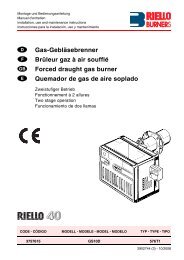
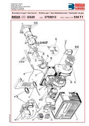
FIRING RATES<br />
18<br />
16<br />
14<br />
P 140 T/G<br />
P 200 T/G<br />
P 300 T/G<br />
P 450 T/G<br />
12<br />
10<br />
8<br />
6<br />
4<br />
hPa (mbar)<br />
2<br />
0<br />
0<br />
50 100 150 200 250 300 350<br />
400<br />
450<br />
kg/h<br />
0<br />
500<br />
1000 1500 2000 2500 3000 3500 4000 4500<br />
5000<br />
kW<br />
Useful working field for choosing the burner<br />
Test conditions conforming to EN 267:<br />
Temperature: 20°C<br />
Pressure: 1013,5 mbar<br />
Altitude: 0 m a.s.l.<br />
3
FUEL SUPPLY<br />
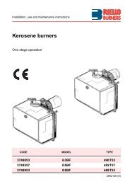
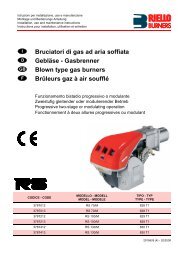
HYDRAULIC CIRCUIT<br />
The burners are fitted with four valves (a safety valve and<br />
three oil delivery valves) and an oil filter along the oil line<br />
from the pump to the nozzle.<br />
A thermostat, on the basis of required heat, regulates oil<br />
delivery valves opening, allowing or not the light oil passage<br />
through the valves. Delivery valves opening supplies the<br />
three stage hydraulic ram which regulates air delivery in<br />
relation to fuel burnt.<br />
The pumping group is fitted with a pump, an oil filter and<br />
a regulating valve, that adjusts atomised pressure.<br />
This value is factory-set at 12 bar but it can be changed by<br />
adjusting pressure regulator fitted on the pump.<br />
Example of the hydraulic circuit on PRESS 200 T/G<br />
EN 267 > 100 Kg/h<br />
P<br />
Pump with oil filter and<br />
pressure regulator<br />
FO<br />
Oil filter<br />
FO<br />
VS<br />
V1<br />
V2<br />
V3<br />
PV<br />
A<br />
U1<br />
U2<br />
V1 - V2 - V3<br />
VS<br />
MT<br />
U1 - U2 - U3<br />
PV<br />
Delivery oil valves<br />
Safety valve<br />
3 stage hydraulic ram<br />
Nozzles<br />
Nozzle holder<br />
P<br />
A<br />
Atomizer<br />
MT<br />
4
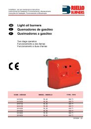
DIMENSIONING OF THE FUEL SUPPLY LINES<br />
The fuel feed must be completed with the safety devices required by the local norms.<br />
The table shows the choice of piping diameter for the various burners, depending on the difference<br />
in height between the burner and the tank and their distance.<br />
Model<br />
Diameter piping<br />
+H, -H (m)<br />
+2,0<br />
+1,5<br />
+1,0<br />
+0,5<br />
0<br />
-0,5<br />
-1,0<br />
-1,5<br />
-2,0<br />
-3,0<br />
MAXIMUM EQUIVALENT LENGTH FOR THE PIPING L[m]<br />
P 140 T/G<br />
P 200 T/G<br />
P 300 T/G<br />
Ø14mm<br />
L max (m)<br />
71<br />
66<br />
61<br />
55<br />
50<br />
45<br />
40<br />
35<br />
29<br />
20<br />
Ø16mm<br />
L max (m)<br />
118<br />
110<br />
102<br />
94<br />
86<br />
78<br />
69<br />
61<br />
53<br />
38<br />
Ø16mm<br />
L max (m)<br />
84<br />
78<br />
72<br />
66<br />
60<br />
54<br />
48<br />
42<br />
36<br />
25<br />
Ø18mm<br />
L max (m)<br />
132<br />
123<br />
114<br />
105<br />
96<br />
87<br />
78<br />
69<br />
60<br />
43<br />
Ø16mm<br />
L max (m)<br />
57<br />
53<br />
49<br />
44<br />
40<br />
36<br />
31<br />
27<br />
23<br />
15<br />
Ø18mm<br />
L max (m)<br />
90<br />
83<br />
77<br />
70<br />
64<br />
58<br />
51<br />
45<br />
39<br />
27<br />
P 450 T/G<br />
Ø16mm Ø18mm<br />
L max (m) L max (m)<br />
40<br />
60<br />
35<br />
55<br />
32<br />
50<br />
30<br />
48<br />
27<br />
43<br />
18<br />
35<br />
15<br />
30<br />
13<br />
25<br />
10<br />
20<br />
5<br />
10<br />
6<br />
7<br />
10<br />
9 5 V<br />
P<br />
+H<br />
10 cm<br />
8<br />
4<br />
7 5 3<br />
9<br />
2<br />
1<br />
H Difference in height pump-foot valve<br />
Ø Internal pipe diameter<br />
P Max. height 10 m<br />
V Height 4 m<br />
1 Burner<br />
2 Burner pump<br />
3 Filter<br />
4 Manual shut off valve<br />
5 Suction pipework<br />
6 Bottom valve<br />
7 Remote controlled rapid manual<br />
shut off valve (compulsory in Italy)<br />
8 Type approved shut off solenoid valve<br />
(compulsory in Italy)<br />
9 Return pipework<br />
10 Check valve<br />
-H<br />
6<br />
note<br />
With ring distribution oil systems, the feasible drawings and dimensioning are the responsibility<br />
of specialised engineering studios, who must check compatibility with the requirements and<br />
features of each single installation.<br />
5
VENTILATION<br />
The ventilation circuit is provided with<br />
forward curve blades centrifugal fan,<br />
which guarantees high pressure levels<br />
at the required air deliveries and permits installation flexibility.<br />
In spite of the remarkable output power and of the very high pressure<br />
performances, structures of PRESS models are extremely compact.<br />
A variable profile cam connects fuel and air setting, ensuring fuel<br />
efficiency in all firing rates.<br />
Example of three stage hydraulic ram<br />
COMBUSTION HEAD<br />
Two different lengths of the<br />
combustion head can be chosen for<br />
the various models of the PRESS T/G<br />
series of burners. The choice depends on the thickness of the front<br />
panel and the type of the boiler.<br />
Depending on the type of heat generator, it is necessary to check<br />
the correct head penetration into the combustion chamber.<br />
The internal position of the combustion head can easily be adjusted<br />
on the basis of required output.<br />
flame dimensions in relation to the burner output. The length and<br />
diameter shown in the diagram below should be employed<br />
preliminary check: it is required a more careful investigation if<br />
combustion chamber dimensions are much different from the reported<br />
values.<br />
1°<br />
2° 3°<br />
Example of a PRESS T/G burner<br />
combustion head<br />
Flame dimensions<br />
7<br />
4<br />
Flame lenght (m)<br />
6<br />
5<br />
4<br />
3<br />
2<br />
1<br />
0<br />
0 1 2 3<br />
L max<br />
L min<br />
D max<br />
D min<br />
3,5<br />
3<br />
2,5<br />
2<br />
1,5<br />
1<br />
0,5<br />
0<br />
4 5 6 7 8 9 10<br />
Burner output (MW)<br />
Flame diameter (m)<br />
D<br />
L<br />
Example:<br />
Burner thermal output = 3500 kW;<br />
L flame (m) = 3,5 m (medium value);<br />
D flame (m) = 1 m (medium value)<br />
6
OPERATION<br />
BURNER OPERATION MODE<br />
With three stage operation, the PRESS T/G burners can follow the temperature load requested by<br />
the system.<br />
A ratio between maximum and minimum working output of 3:1 is reached, thank to a three-hydraulic<br />
ram system: the air delivery is proportional to required output.<br />
On three stage operation, the burner gradually adjusts output to the requested level, by varying<br />
between the three pre-set levels (see picture A).<br />
Three stage operation<br />
Output Controlled variable<br />
°C<br />
bar<br />
max<br />
0<br />
time<br />
time<br />
Picture A<br />
In the following table, are listed maximum output<br />
and fuel deliveries of the burners.<br />
Model<br />
P 140 T/G<br />
P 200 T/G<br />
P 300 T/G<br />
P 450 T/G<br />
Stage Max output<br />
(kW)<br />
1 st 545<br />
2 nd 1103<br />
3 rd 1660<br />
1 st 794<br />
2 nd 1576<br />
3 rd 2372<br />
1 st 1186<br />
2 nd 2372<br />
3 rd 3558<br />
1 st 1780<br />
2 nd 3560<br />
3 rd 5340<br />
Max delivery<br />
(kg/h)<br />
46<br />
93<br />
140<br />
67<br />
133<br />
200<br />
100<br />
200<br />
300<br />
150<br />
300<br />
450<br />
7
All PRESS T/G series burners are fitted with a new microprocessor control panel for the supervision<br />
during intermittent operation.<br />
For helping the commissioning and maintenance work, there are two main elements:<br />
Switch<br />
The lock-out reset button is the central operating element for resetting the burner control<br />
and for activating / deactivating the diagnostic functions.<br />
The multi-color LED is the central indication element for visual diagnosis and interface<br />
diagnosis.<br />
Both elements are located under the transparent cover of lock-out reset button, as showed below.<br />
Switch<br />
There are two diagnostic choices, for indication of operation and diagnosis of fault cause:<br />
- visual diagnosis :<br />
- interface diagnosis :<br />
INTERFACE ADAPTER<br />
COMPUTER<br />
or<br />
by the interface adapter<br />
and a PC with dedicated<br />
software or by a<br />
predisposed flue gas<br />
analyzer (see paragraph<br />
accessories).<br />
FLUE GAS<br />
ANALYSER<br />
8
Indication of operation :<br />
In normal operation, the various status are<br />
indicated in the form of colour codes according<br />
to the table below.<br />
The interface diagnosis (with adapter) can be<br />
activated by pressing the lock-out button for<br />
> 3 seconds.<br />
Diagnosis of fault causes :<br />
Color code table<br />
Operation status<br />
Color code table<br />
Stand-by<br />
Pre-purging<br />
Ignition phase<br />
Flame OK<br />
Poor flame<br />
Undervoltage, built-in fuse<br />
Fault, alarm<br />
Extraneous light<br />
LED off<br />
After lock-out has occurred, the red signal lamp is steady on. In this status, the visual fault diagnosis<br />
according to the error code table can be activated by pressing the lock-out reset button for > 3 seconds.<br />
The interface diagnosis (with adapter) can be activated by pressing again the lock-out button for > 3<br />
seconds.<br />
The flashes of red LED are a signal with this sequence :<br />
(e.g. signal with n° 3 flashes – faulty air pressure monitor)<br />
LED off<br />
3 sec. 3 sec. 3 sec.<br />
Possible cause of fault<br />
Error code table<br />
No establishment of flame at the end of safety time : - faulty or soiled fuel valves<br />
- faulty or soiled flame detector<br />
- poor adjustment of burner, no fuel<br />
- faulty ignition equipment<br />
Faulty air pressure monitor<br />
Extraneous light or simulation of flame on burner start up<br />
Flash code<br />
2 flashes<br />
3 flashes<br />
4 flashes<br />
Loss of flame during operation :<br />
Wiring error or internal fault<br />
- faulty or soiled fuel valves<br />
- faulty or soiled flame detector<br />
- poor adjustment of burner<br />
7 flashes<br />
10 flashes<br />
START UP CYCLE<br />
M<br />
TL<br />
2<br />
Start up procedure is referred to a three stage<br />
operation<br />
VS<br />
VF1<br />
VF2<br />
VF3<br />
Lock-out<br />
0<br />
3<br />
25<br />
25<br />
32<br />
30<br />
39<br />
time (s)<br />
0s The burner begins the firing cycle.<br />
2s The motor starts: pre-purge phase.<br />
3s Ignition electrode sparks.<br />
25s Safety valve VS and 1 st stage valve VF1 open.<br />
30s The spark goes out.<br />
32s 2 nd stage valve VF2 opens.<br />
39s 3 rd stage valve VF3 opens, start up cycle is<br />
concluded.<br />
9
WIRING DIAGRAMS<br />
Electrical connections must be made<br />
by qualified and skilled personnel,<br />
according to the local norms.<br />
0 1 2<br />
3<br />
P 200 T/G<br />
Example of control panel for<br />
P 200 T/G models<br />
“<strong>THREE</strong> <strong>STAGE</strong>” OPERATION<br />
Direct start-up version P 140-200-300 T/G<br />
MB<br />
L1 L2 L3 N<br />
L<br />
N S3 T1 30 T2<br />
T6 T8 T9<br />
T11<br />
R3 31<br />
F<br />
L<br />
PE L1 L2 L3 N<br />
3N ~ 50Hz 400/230V<br />
3 50Hz 230V<br />
P<br />
TS<br />
T6A<br />
L N<br />
~ 50Hz 230V<br />
M<br />
3~<br />
S<br />
P<br />
TL<br />
IN<br />
P<br />
T2<br />
P<br />
T3<br />
PS<br />
MB - Burner terminal board<br />
TS - Safety thermostat<br />
S - External lock-out signal<br />
IN - Manual switch<br />
TL - Threshold thermostat<br />
T2 - 2 nd stage thermostat<br />
T3 - 3 rd stage thermostat<br />
T6A - 6A fuse<br />
F - Fuse (see table A)<br />
L - Lead section (see table A)<br />
PS - Lock out reset button<br />
Star delta start-up version P 300-450 T/G<br />
MB<br />
E<br />
PE L1 L2 L3 N<br />
U1V1 W1U2 V2 W2 N<br />
1 2 3 4 35 36 3738 39 40 41 42 43 44 45 5 6<br />
MA<br />
F<br />
L<br />
ST1<br />
V20<br />
V21<br />
3N~<br />
50Hz 400/230V<br />
3~ 50Hz 230V<br />
S1 L<br />
N S3 T1 30 T2 T6 T8 T9 R3 31<br />
TS<br />
TL<br />
P<br />
P<br />
P PS<br />
S<br />
T2<br />
M<br />
3~<br />
T6A<br />
IN<br />
T11<br />
P<br />
T2<br />
MB - Burner terminal board<br />
TS - Safety thermostat<br />
S - External lock-out signal<br />
IN - Manual switch<br />
TL - Threshold thermostat<br />
MA - Star-delta starter terminal strip<br />
T2 - 2 nd stage thermostat<br />
T3 - 3 rd stage thermostat<br />
T6A - 6A fuse<br />
F - Fuse (see table A)<br />
L - Lead section (see table A)<br />
PS - Lock out reset button<br />
The following table<br />
shows the supply lead<br />
sections and the type of<br />
fuse to be used.<br />
Model<br />
F<br />
L<br />
E<br />
(A)<br />
(mm 2 )<br />
(mm 2 )<br />
P 140 T/G<br />
230V<br />
T25<br />
2,5<br />
-<br />
400V<br />
T25<br />
2,5<br />
-<br />
Direct<br />
P 200 T/G<br />
230V<br />
T35<br />
4<br />
-<br />
400V<br />
T25<br />
2,5<br />
-<br />
P 300 T/G<br />
230V<br />
T63<br />
6<br />
-<br />
400V<br />
T50<br />
4<br />
-<br />
P 300 T/G<br />
230V<br />
T50<br />
6<br />
4<br />
Star delta<br />
400V<br />
T35<br />
4<br />
2,5<br />
P 450 T/G<br />
230V<br />
T63<br />
10<br />
6<br />
400V<br />
T50<br />
6<br />
4<br />
Table A<br />
10
EMISSIONS<br />
mg/kWh<br />
250<br />
200<br />
NOx EMISSIONS<br />
150<br />
100<br />
50<br />
0<br />
P 140 T/G P 200 T/G P 300 T/G P 450 T/G<br />
mg/kWh<br />
70<br />
60<br />
CO EMISSIONS<br />
50<br />
40<br />
30<br />
20<br />
10<br />
0<br />
P 140 T/G P 200 T/G P 300 T/G P 450 T/G<br />
dB(A)<br />
100<br />
80<br />
NOISE EMISSIONS<br />
60<br />
40<br />
20<br />
0<br />
P 140 T/G P 200 T/G P 300 T/G P 450 T/G<br />
The emission data has been measured in the various models at maximum output, according to<br />
EN 267 standard.<br />
11
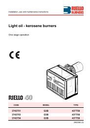
OVERALL DIMENSIONS (mm)<br />
BURNER<br />
A<br />
E F - F (1)<br />
O - O (1)<br />
H<br />
I<br />
B<br />
Model A B E F - F (1) H I<br />
P 140 T/G<br />
P 200 T/G<br />
P 300 T/G<br />
P 450 T/G<br />
765<br />
796<br />
858<br />
950<br />
365<br />
396<br />
447<br />
508<br />
(1) Length with extended combustion head.<br />
890<br />
890<br />
1000<br />
1070<br />
363<br />
391<br />
444<br />
476<br />
-<br />
-<br />
-<br />
-<br />
473<br />
501<br />
574<br />
606<br />
222<br />
250<br />
295<br />
336<br />
467<br />
467<br />
496<br />
525<br />
O<br />
1250<br />
1280<br />
1440<br />
1546<br />
-<br />
-<br />
-<br />
-<br />
-<br />
O (1)<br />
1360<br />
1390<br />
1570<br />
1676<br />
BURNER - B<strong>OIL</strong>ER MOUNTING FLANGE<br />
L<br />
O<br />
L<br />
M<br />
N<br />
M<br />
Model<br />
P 140 T/G<br />
P 200 T/G<br />
P 300 T/G<br />
P 450 T/G<br />
L<br />
260<br />
260<br />
260<br />
310<br />
M<br />
230<br />
-<br />
-<br />
-<br />
N Ø<br />
M14<br />
M16<br />
M18<br />
M20<br />
O<br />
225<br />
255<br />
300<br />
340<br />
PACKAGING<br />
Z<br />
X - X (1)<br />
Y<br />
Model X - X (1) Y Z kg<br />
P 140 T/G<br />
P 200 T/G<br />
P 300 T/G<br />
P 450 T/G<br />
1500<br />
1500<br />
1780<br />
1780<br />
(1) Length with extended combustion head.<br />
930<br />
930<br />
1085<br />
1085<br />
905<br />
905<br />
990<br />
990<br />
130<br />
220<br />
238<br />
300<br />
12
INSTALLATION DESCRIPTION<br />
Installation, start-up and maintenance must be carried out by<br />
qualified and skilled personnel.<br />
All operations must be performed in accordance with the<br />
technical handbook supplied to the burner.<br />
BURNER SETTING<br />
All the burners have slide bars, for easier installation and maintenance.<br />
After removing the cover, the split pin and the pin, the nuts and the screws, dismantle the blast<br />
tube from the burner and fix it to the boiler.<br />
Adjust the combustion head.<br />
Refit the burner casing to the slide bars.<br />
Install the nozzles, choosing it on the basis of the maximum boiler output and following the<br />
diagrams included in the burner instruction handbook.<br />
Check the position of the electrodes.<br />
Close the burner, fasten the screws, the nuts, the split pin and the pin.<br />
HYDRAULIC AND ELECTRICAL CONNECTIONS AND START-UP<br />
The burners are supplied for connection to two pipes fuel supply system.<br />
Connect the ends of the flexible pipes to the suction and return pipework using the supplied<br />
nipples.<br />
Make the electrical connections to the burner following the wiring diagrams included in the<br />
instruction handbook.<br />
Prime the pump by turning the motor (after checking rotation direction).<br />
On start up, check:<br />
- Pressure pump and valve unit regulator (to max. and min.)<br />
- Combustion quality, in terms of unburned substances and excess air.<br />
13
BURNER ACCESSORIES<br />
Nozzles<br />
The nozzles are part of the standard equipment. The following table shows the features and codes on<br />
the basis of the required output. For the choice of the three related nozzles, refer to the burner handbook.<br />
Nozzle type 60° B<br />
Burner GPH Rated output (kg/h) Nozzle<br />
at 10 bar at 12 bar at 14 bar code<br />
P 140 T/G<br />
3,50 13,5 14,8 16,1 3042162<br />
P 140 T/G<br />
4,00 15,4 17 18,4 3042172<br />
P 140 T/G<br />
4,50 17,3 19,1 20,7 3042182<br />
P 140 T/G - P 200 T/G 5,00 19,2 21,2 23 3042192<br />
P 140 T/G - P 200 T/G 5,50 21,1 23,3 25,3 3042202<br />
P 140 T/G - P 200 T/G 6,00 23,1 25,5 27,7 3042212<br />
P 140 T/G - P 200 T/G 6,50 25 27,6 30 3042222<br />
P 140 T/G - P 200 T/G 7,00 26,9 29,7 32,3 3042232<br />
P 140 T/G - P 200 T/G 7,50 28,8 31,8 34,6 3042242<br />
P 140 T/G - P 200 T/G 8,00 30,8 33,9 36,9 3042252<br />
P 140 T/G - P 200 T/G 8,50 32,7 36,1 39,2 3042262<br />
P 140 T/G - P 200 T/G 9,50 36,5 40,3 43,8 3042282<br />
P 140 T/G - P 200 T/G 10,00 38,4 42,4 46,1 3042292<br />
P 140 T/G - P 200 T/G 11,00 42,3 46,7 50,7 3042312<br />
P 200 T/G<br />
12,00 46,1 50,9 55,3 3042322<br />
P 200 T/G<br />
13,00 50 55,1 59,9 3042332<br />
P 200 T/G - P 300 T/G 14,00 53,8 59,4 64,5 3042352<br />
P 200 T/G - P 300 T/G 15,00 57,7 63,6 69,2 3042362<br />
P 300 T/G<br />
16,00 61,5 67,9 73,8 3042382<br />
P 300 T/G<br />
17,00 65,4 72,1 78,4 3042392<br />
P 300 T/G - P 400 T/G 18,00 69,2 76,4 83 3042412<br />
P 300 T/G - P 400 T/G 19,00 73 80,6 87,6 3042422<br />
P 300 T/G - P 400 T/G 20,00 76,9 84,8 92,2 3042442<br />
P 300 T/G - P 400 T/G 22,00 84,6 93,3 101,4 3042462<br />
P 300 T/G - P 400 T/G 24,00 92,2 101,8 110,6 3042472<br />
P 450 T/G<br />
26,00 99,9 110,3 119,9 3042482<br />
P 450 T/G<br />
28,00 107,6 118,8 129,1 3042492<br />
P 450 T/G<br />
30,00 110,4 122 132,4 3042502<br />
P 450 T/G<br />
32,00 117,8 130,1 150,1 3042512<br />
P 450 T/G<br />
35,00 128,8 142,1 154,5 3042522<br />
14
Spacer kit<br />
If burner head penetration in the combustion chamber needs reducing, varying thickness spacers are<br />
available, as given in the following table.<br />
Spacer kit<br />
S<br />
Burner<br />
P 140 T/G<br />
P 200 T/G<br />
P 300 T/G<br />
P 450 T/G<br />
Spacer thickness S (mm)<br />
110<br />
110<br />
130<br />
130<br />
Spacer code<br />
3000722<br />
3000722<br />
3000723<br />
3000751<br />
Sound proofing box<br />
If noise emissions need reducing, sound proofing hoods are available, as given in the following table.<br />
Burner<br />
P 140 T/G - P 200 T/G<br />
P 300 T/G - P 450 T/G<br />
(*) according to EN 15036-1 standard<br />
Sound proofing box<br />
Box type<br />
Average noise<br />
reduction [dB(A)] (*)<br />
C4/5<br />
10<br />
C7<br />
10<br />
Box code<br />
3010404<br />
3010376<br />
Burner support<br />
For easier maintenance, a mobile burner support has been designed, which means the burner can<br />
be dismantled without the need of forklift trucks.<br />
Burner<br />
P 300 T/G - P 450 T/G<br />
Burner support<br />
Support code<br />
3000731<br />
PC interface kit<br />
To connect the flame control panel to a personal computer for the transmission of operation, fault<br />
signals and detailed service information, an interface adapter with PC software are available.<br />
Burner<br />
P140-200-300-450 T/G<br />
PC interface kit<br />
Kit code<br />
3002719<br />
15
SPECIFICATION<br />
A specific index guides your choice of burner from<br />
the various models available in the PRESS series.<br />
Below there is a clear and detailed specification<br />
description of the product.<br />
DESIGNATION OF SERIES<br />
Series :<br />
PRESS<br />
Size 140 ... 450<br />
Operation : T/G Three stage<br />
P/G Modulating<br />
Emission : ... Class 1 EN267<br />
Head : TC Standard head<br />
TL Extended head<br />
Flame control system :<br />
FS1 Standard (1 stop every 24 h)<br />
FS2 Continuous working (1 stop every 72 h)<br />
Electrical supply to the system :<br />
3/230/50 3/230V/50Hz<br />
3/400/50 3N/400V/50Hz<br />
3/230-400/50 3/230V/50Hz - 3N/400V/50Hz<br />
3/220-380/60 3/220/60Hz - 3N/380V/60Hz<br />
3/200/50-60 3/200V/50-60Hz<br />
Auxiliary voltage :<br />
230/50 230V/50Hz<br />
220/60 220V/60Hz<br />
110/50-60 110V/50-60Hz<br />
PRESS 140 T/G TC FS1 3/230-400/50 230/50-60<br />
BASIC DESIGNATION<br />
EXTENDED DESIGNATION<br />
AVAILABLE BURNER MODELS<br />
P 140 T/G TC 3/230-400/50 230/50<br />
P 140 T/G TL 3/230-400/50 230/50<br />
P 200 T/G TC 3/230-400/50 230/50<br />
P 200 T/G TL 3/230-400/50 230/50<br />
P 300 T/G TC 3/230-400/50 230/50<br />
P 300 T/G TL 3/230-400/50 230/50<br />
P 300 T/G TC 3/230/50 230/50<br />
P 300 T/G TL 3/230/50 230/50<br />
P 300 T/G TC 3/400/50 230/50<br />
P 300 T/G TL 3/400/50 230/50<br />
P 450 T/G TC 3/230/50 230/50<br />
P 450 T/G TL 3/230/50 230/50<br />
P 450 T/G TC 3/400/50 230/50<br />
P 450 T/G TL 3/400/50 230/50<br />
Other models are available on request.<br />
16
PRODUCT SPECIFICATION<br />
Burner:<br />
Monoblock forced draught oil burner with three stage operation, fully automatic, made up of:<br />
- Air suction circuit lined with sound-proofing material<br />
- Fan with forward curved blades high performance pressure levels<br />
- Air dampers for air setting controlled by a three stage hydraulic ram<br />
- Starting motor at 2850 rpm, three-phase 400 V with neutral, 50 Hz<br />
- Combustion head, that can be set on the basis of the combustion output, fitted with:<br />
- stainless steel end cone, resistant to corrosion and high temperatures<br />
- ignition electrodes<br />
- flame stability disk<br />
- Gears pump for high pressure fuel supply, fitted with:<br />
- filter<br />
- pressure regulator<br />
- connections for installing a pressure gauge and vacuometer<br />
- internal by-pass for single pipe installation<br />
- Valve unit with a oil safety valve and three oil delivery valves on the output circuit;<br />
- Photocell for flame detection<br />
- Microprocessor based flame control panel, with diagnostic function<br />
- Burner on/off switch<br />
- Flame inspection window<br />
- Slide bars for easier installation and maintenance<br />
- Protection filter against radio interference<br />
- IP 40 electric protection level.<br />
Conforming to:<br />
- 89/336 (2004/108) EC directive (electromagnetic compatibility)<br />
- 73/23 (2006/95) EC directive (low voltage)<br />
- 92/42/EC directive (performance)<br />
- 98/37/EC directive (machinery)<br />
- EN 267 (liquid fuel burners).<br />
Standard equipment:<br />
- 2 flexible pipes for connection to the oil supply network<br />
- 2 nipples for the connection to the pump<br />
- 4 wiring looms fittings for electrical connections<br />
- 4 screws for fixing the burner flange to the boiler<br />
- Instruction handbook for installation, use and maintenance<br />
- Spare parts catalogue<br />
- 2 slide bar extensions (for the extended head models of P 300 T/G and P 450 T/G)<br />
- 3 nozzles<br />
- Gasket for flange<br />
- Starter (*)<br />
- Diffuser disk (P 450 T/G).<br />
(*) For versions with star-delta starting.<br />
Available accessories to be ordered separately:<br />
- Nozzles<br />
- Spacer kit<br />
- Sound-proofing box<br />
- Burner support<br />
- PC interface kit.<br />
17
TS0038UK03 - 1/2008<br />
RIELLO S.p.A. - Via Ing. Pilade Riello, 5 - 37045 Legnago (VR) Italy<br />
Tel. ++39.0442630111 - Fax ++39.044221980<br />
Internet: http://www.<strong>riello</strong>burners.com - E-mail: info@<strong>riello</strong>burners.com<br />
Since the Company is constantly engaged in the production improvement, the aesthetic and<br />
dimensional features, the technical data, the equipment and the accessories can be changed.<br />
This document contains confidential and proprietary information of RIELLO S.p.A.<br />
Unless authorised, this information shall not be divulged, nor duplicated in whole or in part.