Tradesmig 180-210-260-1 - Murex
Tradesmig 180-210-260-1 - Murex
Tradesmig 180-210-260-1 - Murex

Create successful ePaper yourself
Turn your PDF publications into a flip-book with our unique Google optimized e-Paper software.
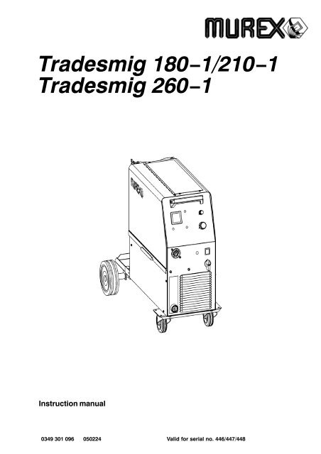
<strong>Tradesmig</strong> <strong>180</strong>−1/<strong>210</strong>−1<br />
<strong>Tradesmig</strong> <strong>260</strong>−1<br />
Instruction manual<br />
0349 301 096 050224<br />
Valid for serial no. 446/447/448
DECLARATION OF CONFORMITY<br />
<strong>Murex</strong> Welding Products Ltd.<br />
Declare hereby that:<br />
<strong>Murex</strong> <strong>Tradesmig</strong> <strong>180</strong> -1/<strong>210</strong> -1/<strong>260</strong> -1<br />
Part No. 0349 308 040, 0349 308 050, 0349 308 060<br />
Manufactured after 1st May 2005<br />
S<br />
S<br />
S<br />
S<br />
conform with the requirements of Council Directive 72/23/EEC, amended by<br />
Council Directive 93/68/EEC, relating to electrical equipment designed for use<br />
within certain voltage limits.<br />
conform with the requirements of Council Directive 89/336/EEC, amended by<br />
Council Directive 93/68/EEC, relating to electromagnetic compatibility.<br />
are manufactured in accordance with EN60974-1 Safety Requirements for Arc<br />
Welding Equipment.<br />
are manufactured in accordance with EN50199 Electromagnetic Compatibility for<br />
Arc Welding Equipment.<br />
On behalf of o<strong>Murex</strong> Welding Products Ltd.<br />
Hanover House, Queensgate<br />
Britannia Road, Waltham Cross<br />
Herts. EN8 7TF<br />
England<br />
Henry Selenius<br />
Vice President<br />
ESAB Welding Equipment AB<br />
695 81 LAXA<br />
SWEDEN<br />
Manufactured by Esab Welding Equipment AB.<br />
declaration<br />
- 2 -
ENGLISH<br />
1 SAFETY . . . . . . . . . . . . . . . . . . . . . . . . . . . . . . . . . . . . . . . . . . . . . . . . . . . . . . . . . . . 4<br />
2 INTRODUCTION . . . . . . . . . . . . . . . . . . . . . . . . . . . . . . . . . . . . . . . . . . . . . . . . . . . 6<br />
2.1 Equipment . . . . . . . . . . . . . . . . . . . . . . . . . . . . . . . . . . . . . . . . . . . . . . . . . . . . . . . . . . . . . . . . 6<br />
3 TECHNICAL DATA . . . . . . . . . . . . . . . . . . . . . . . . . . . . . . . . . . . . . . . . . . . . . . . . . 6<br />
4 INSTALLATION . . . . . . . . . . . . . . . . . . . . . . . . . . . . . . . . . . . . . . . . . . . . . . . . . . . . 8<br />
4.1 Placing . . . . . . . . . . . . . . . . . . . . . . . . . . . . . . . . . . . . . . . . . . . . . . . . . . . . . . . . . . . . . . . . . . . 8<br />
4.2 Assembly of components . . . . . . . . . . . . . . . . . . . . . . . . . . . . . . . . . . . . . . . . . . . . . . . . . . . 8<br />
4.3 Electrical installation . . . . . . . . . . . . . . . . . . . . . . . . . . . . . . . . . . . . . . . . . . . . . . . . . . . . . . . 9<br />
4.4 Mains power supply . . . . . . . . . . . . . . . . . . . . . . . . . . . . . . . . . . . . . . . . . . . . . . . . . . . . . . . . 9<br />
5 OPERATION . . . . . . . . . . . . . . . . . . . . . . . . . . . . . . . . . . . . . . . . . . . . . . . . . . . . . . . 10<br />
5.1 Connection and control devices . . . . . . . . . . . . . . . . . . . . . . . . . . . . . . . . . . . . . . . . . . . . . 10<br />
5.2 Functions explanation . . . . . . . . . . . . . . . . . . . . . . . . . . . . . . . . . . . . . . . . . . . . . . . . . . . . . . 11<br />
6 MAINTENANCE . . . . . . . . . . . . . . . . . . . . . . . . . . . . . . . . . . . . . . . . . . . . . . . . . . . . 11<br />
6.1 Inspection and cleaning . . . . . . . . . . . . . . . . . . . . . . . . . . . . . . . . . . . . . . . . . . . . . . . . . . . . 11<br />
7 FAULT TRACING . . . . . . . . . . . . . . . . . . . . . . . . . . . . . . . . . . . . . . . . . . . . . . . . . . . 12<br />
DIAGRAM . . . . . . . . . . . . . . . . . . . . . . . . . . . . . . . . . . . . . . . . . . . . . . . . . . . . . . . . . . . . 13<br />
WEAR COMPONENTS . . . . . . . . . . . . . . . . . . . . . . . . . . . . . . . . . . . . . . . . . . . . . . . . . 17<br />
ACCESSORIES . . . . . . . . . . . . . . . . . . . . . . . . . . . . . . . . . . . . . . . . . . . . . . . . . . . . . . . 18<br />
TOCe<br />
− 3 −
1 SAFETY<br />
Users of welding equipment have the ultimate responsibility for ensuring that anyone who works on<br />
or near the equipment observes all the relevant safety precautions. Safety precautions must meet<br />
the requirements that apply to this type of welding equipment. The following recommendations<br />
should be observed in addition to the standard regulations that apply to the workplace.<br />
All work must be carried out by trained personnel well−acquainted with the operation of the welding<br />
equipment. Incorrect operation of the equipment may lead to hazardous situations which can result<br />
in injury to the operator and damage to the equipment.<br />
1. Anyone who uses the welding equipment must be familiar with:<br />
its operation<br />
location of emergency stops<br />
its function<br />
relevant safety precautions<br />
welding<br />
2. The operator must ensure that:<br />
no unauthorised person is stationed within the working area of the equipment when it is<br />
started up.<br />
no−one is unprotected when the arc is struck<br />
3. The workplace must:<br />
be suitable for the purpose<br />
be free from draughts<br />
4. Personal safety equipment<br />
Always wear recommended personal safety equipment, such as safety glasses, flame−proof<br />
clothing, safety gloves.<br />
Do not wear loose−fitting items, such as scarves, bracelets, rings, etc., which could become<br />
trapped or cause burns.<br />
5. General precautions<br />
Make sure the return cable is connected securely.<br />
Work on high voltage equipment may only be carried out by a qualified electrician.<br />
Appropriate fire extinquishing equipment must be clearly marked and close at hand.<br />
Lubrication and maintenance must not be carried out on the equipment during operation.<br />
T1725e<br />
− 4 −
WARNING<br />
ARC WELDING AND CUTTING CAN BE INJURIOUS TO YOURSELF AND OTHERS. TAKE PRECAU-<br />
TIONS WHEN WELDING. ASK FOR YOUR EMPLOYER’S SAFETY PRACTICES WHICH SHOULD BE<br />
BASED ON MANUFACTURERS’ HAZARD DATA.<br />
ELECTRIC SHOCK − Can kill<br />
Install and earth the welding unit in accordance with applicable standards.<br />
Do not touch live electrical parts or electrodes with bare skin, wet gloves or wet clothing.<br />
Insulate yourself from earth and the workpiece.<br />
Ensure your working stance is safe.<br />
FUMES AND GASES − Can be dangerous to health<br />
Keep your head out of the fumes.<br />
Use ventilation, extraction at the arc, or both, to take fumes and gases away from your breathing zone<br />
and the general area.<br />
ARC RAYS − Can injure eyes and burn skin.<br />
Protect your eyes and body. Use the correct welding screen and filter lens and wear protective<br />
clothing.<br />
Protect bystanders with suitable screens or curtains.<br />
FIRE HAZARD<br />
Sparks (spatter) can cause fire. Make sure therefore that there are no inflammable materials nearby.<br />
NOISE − Excessive noise can damage hearing<br />
Protect your ears. Use earmuffs or other hearing protection.<br />
Warn bystanders of the risk.<br />
MALFUNCTION − Call for expert assistance in the event of malfunction.<br />
READ AND UNDERSTAND THE INSTRUCTION MANUAL BEFORE INSTALLING OR OPERATING.<br />
PROTECT YOURSELF AND OTHERS!<br />
WARNING!<br />
Read and understand the instruction manual<br />
before installing or operating.<br />
WARNING!<br />
Do not use the power source for thawing frozen pipes.<br />
This product is solely intended for arc welding.<br />
T1725e<br />
− 5 −
2 INTRODUCTION<br />
<strong>Tradesmig</strong> <strong>180</strong>−1/<strong>210</strong>−1/<strong>260</strong>−1 are step controlled power sources in a compact design, intended for<br />
welding with solid steel, stainless steel or aluminium wire as well as tubular wire with or without<br />
shielding gas.<br />
2.1 Equipment<br />
The power source is supplied with:<br />
<br />
<br />
<br />
Return cable 3m with return clamp<br />
Shelf for gas cylinder<br />
Instruction manual<br />
3 TECHNICAL DATA<br />
Voltage<br />
Permissible load at<br />
100% duty cycle 76A<br />
60 % duty cycle 98A<br />
30 % duty cycle 139A<br />
20 % duty cycle 170A<br />
Setting range (DC)<br />
Open circuit voltage<br />
Open circuit power<br />
<strong>Tradesmig</strong> <strong>180</strong>−1<br />
240V, 1∼ 50/60Hz<br />
30A/15,5V−<strong>180</strong>A/19,3V<br />
19,5−35,5V<br />
145W<br />
Power factor at max load 0,90<br />
Control voltage<br />
Wire feed speed<br />
Burnback time<br />
Spot welding<br />
Welding gun connection<br />
Wire dimension range<br />
Max diameter/weight<br />
of wire bobin<br />
Dimensions lxwxh<br />
Weight<br />
Operating temperature<br />
42V, 50/60Hz<br />
1,0−17m/min<br />
0,02−0,25s<br />
0,2−2,5s<br />
EURO<br />
0,6−0,8(Fe)<br />
1,0(Al)<br />
0,8(cored)<br />
300mm/15kg<br />
860x420x730<br />
59kg<br />
Enclosure class IP 23<br />
Application classification<br />
−10 ÷ +40 o C<br />
T1725e<br />
− 6 −
<strong>Tradesmig</strong> <strong>210</strong>−1<br />
<strong>Tradesmig</strong> <strong>260</strong>−1<br />
Voltage 240V, 1∼ 50/60Hz 240V, 1∼ 50/60Hz<br />
Permissible load at<br />
100% duty cycle 90A 110A<br />
60 % duty cycle 115A 140A<br />
30 % duty cycle 163A 200A<br />
20 % duty cycle 200A 250A<br />
Setting range (DC) 30A/15,5V−<strong>210</strong>A/18V 40A/16,0V−<strong>260</strong>A/22,5V<br />
Open circuit voltage 17,5−33,0V 19,5−42,5V<br />
Open circuit power 240W 200W<br />
Power factor at max load 0,83 0,92<br />
Control voltage 42V, 50/60Hz 42V, 50/60Hz<br />
Wire feed speed 1,0−17m/min 1,9−19m/min<br />
Burnback time 0,02−0,25s 0−0,25s<br />
Spot welding 0,2−2,5s 0,2−2,5s<br />
Welding gun connection EURO EURO<br />
Wire dimension range<br />
Max diameter/weight<br />
of wire bobin<br />
0,6−1,0(Fe)<br />
1,0(Al)<br />
0,8−1,0(cored)<br />
300mm/15kg<br />
0,6−1,2(Fe)<br />
1,0−1,2(Al)<br />
0,8−1,2(cored)<br />
300mm/15kg<br />
Dimensions lxwxh 860x420x730 860x420x730<br />
Weight 68kg 94kg<br />
Operating temperature −10 ÷ +40 o C −10 ÷ +40 o C<br />
Enclosure class IP 23 IP 23<br />
Application classification<br />
Duty cycle<br />
The duty cycle refers to the time as a percentage of a ten−minute period that you can weld at a certain<br />
load without overloading.<br />
Enclosure class<br />
The IP code indicates the enclosure class, i. e. the degree of protection against penetration by solid<br />
objects or water. Equipment marked IP23 is designed for indoor and outdoor use.<br />
Application class<br />
The symbol indicates that the power source is designed for use in areas with increased<br />
electrical hazard.<br />
T1725e<br />
− 7 −
4 INSTALLATION<br />
The installation must be executed by a professional.<br />
WARNING!<br />
This product is intended for industrial use. In a domestic environment this product may cause radio<br />
interference. It is the user’s responsibility to take adequate precautions.<br />
4.1 Placing<br />
Position the welding power source such way that its cooling air inlets and outlets are<br />
not obstructed.<br />
4.2 Assembly of components<br />
WARNING!<br />
For packing and shipment of the machine the wheels are detached from the unit.<br />
Before use attach the wheels according to instruction.<br />
1.<br />
2.<br />
3.<br />
T1725e<br />
− 8 −
4.3 Electrical installation<br />
4.4 Mains power supply<br />
Check that the unit is connected to the correct mains power supply voltage, and that it is protected by<br />
the correct fuse size. A protective earth connection must be made, in accordance with regulations.<br />
Rating plate with supply connection data<br />
<strong>Tradesmig</strong> <strong>180</strong>−1 <strong>Tradesmig</strong> <strong>210</strong>−1 <strong>Tradesmig</strong> <strong>260</strong>−1<br />
Voltage V 240V, 1∼ 50/60Hz 240V, 1∼ 50/60Hz 240V, 1∼ 50/60Hz<br />
Current A<br />
at 100% duty cycle 10,4 14,3 16,6<br />
at 60% duty cycle 15,0 17,6 23,4<br />
at 20% duty cycle 29 32,5 47,5<br />
Cable area mm 3 x 1.5 3 x 2.5 3 x 4,0<br />
Fuse slow A 16 16 35<br />
T1725e<br />
− 9 −
5 OPERATION<br />
General safety regulations for the handling of the equipment can be found on<br />
page 4. Read through before you start using the equipment!<br />
WARNING!<br />
Rotating parts can cause injury, take great care.<br />
WARNING − TIPPING RISK!<br />
There is a risk of tipping while transportation and operation, if the welding machine leans<br />
more than 10 o . In that case appropriate securing has to be provided !<br />
5.1 Connection and control devices<br />
1 Mains supply switch with indicating lamp 6 Knob for spot welding − ON/OFF and time<br />
setting<br />
2 Orange indicating lamp, overheating 7 Knob for wire speed setting<br />
3 Welding voltage switch<br />
T<strong>180</strong>−1: 8 steps<br />
T<strong>210</strong>−1: 12 steps<br />
T<strong>260</strong>−1: 12 steps<br />
8 Digital instrument − V/A,<br />
(option,see page 18)<br />
4 EURO − connector for welding gun 9 Knob for burn−back time setting.<br />
In T<strong>260</strong>−1 located in wire feeder compartment,<br />
in T<strong>180</strong>−1/T<strong>210</strong>−1 located on control<br />
board.<br />
5 Connection for return cable (−)<br />
T1725e<br />
− 10 −
5.2 Functions explanation<br />
5.2.1 Overheating protection<br />
When the machine is switched on with the mains switch [1], indicating lamp [1] is on and<br />
lamp [2] off − the machine is ready to operate. If the internal temperature becomes too<br />
high, the welding is interrupted and disabled. This state is indicated by lighting of the<br />
orange indicating lamp [2] on the front of the machine. It resets automatically when the<br />
temperature has fallen.<br />
6 MAINTENANCE<br />
Regular maintenance is important for safe, reliable operation.<br />
Note!<br />
All guarantee undertakings from the supplier cease to apply if the customer himself<br />
attempts any work in the product during the guarantee period in order to rectify any<br />
faults.<br />
6.1 Inspection and cleaning<br />
Check regularly that the power source is free from dirt.<br />
The power source should be regularly blown clean using dry compressed air at reduced<br />
pressure. More frequently in dirty environments. Otherwise the air inlet/outlet may become<br />
blocked and cause overheating.<br />
Welding gun<br />
<br />
Cleaning and replacement of the welding gun’s wear parts should take place at<br />
regular intervals in order to achieve trouble−free wire feed. Blow the wire guide<br />
clean regularly and clean the contact tip.<br />
The brake hub<br />
The hub is adjusted when delivered, if<br />
readjustment is required, follow the instructions<br />
below. Adjust the brake hub so that wire is slightly<br />
slack when wire feed stops.<br />
<br />
Adjusting the braking torque:<br />
Turn the red handle to the locked position.<br />
Insert a screwdriver into the springs in the hub.<br />
Turn the springs clockwise to reduce the braking torque<br />
Turn the springs anticlockwise to increase the braking torque. NB: Turn both<br />
springs through the same amount.<br />
T1725e<br />
− 11 −
7 FAULT TRACING<br />
Try these recommended checks and inspections before sending for an authorised service technican.<br />
Type of fault<br />
Actions<br />
No arc Check that the mains power supply switch is turned on.<br />
Check that the welding current supply and return cables are<br />
correctly connected.<br />
Check that correct current value is set.<br />
Welding current is interrupted<br />
during welding<br />
Thermal overload trips<br />
operate frequently<br />
<br />
<br />
<br />
<br />
Check whether the thermal overload trip has operated<br />
(indicated by the orange lamp on the front).<br />
Check the main power supply fuses.<br />
Check to see whether the air inlets/outlets are clogged.<br />
Make sure that you are not exceeding the rated data for the<br />
power source (i.e. that the unit is not being overloaded).<br />
Poor welding performance Check that the welding current supply and return cables are<br />
correctly connected.<br />
Check that the correct current value is set.<br />
Check that the correct welding wires are being used.<br />
Check the main power supply fuses.<br />
<br />
Check the wire feed unit − if proper rolls are applied and<br />
properly set the pressure of the wire feeder’s pressure rollers<br />
<strong>Tradesmig</strong> <strong>180</strong>−1/<strong>210</strong>−1/<strong>260</strong>−1 is designed and tested in accordance with the international<br />
and European standards IEC/EN 60974−1 and EN 50199. It is the obligation of the<br />
service unit which has carried out the service or repair work to make sure that the product<br />
still conforms to the said standard.<br />
T1725e<br />
− 12 −
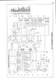
Diagram<br />
<strong>Tradesmig</strong> <strong>180</strong>−1, 240V<br />
dT1725<br />
− 13 −
<strong>Tradesmig</strong> <strong>210</strong>−1, 240V<br />
dT1725<br />
− 14 −
<strong>Tradesmig</strong> <strong>260</strong>−1, 240V<br />
dT1725<br />
− 15 −
<strong>Tradesmig</strong> <strong>180</strong>−1/<strong>210</strong>−1/<strong>260</strong>−1<br />
Valid for serial no. 446/447/448−XXX−XXXX<br />
Ordering numbers<br />
0349 308 040 <strong>Tradesmig</strong> <strong>180</strong>−1 240V 150/60Hz<br />
0349 308 050 <strong>Tradesmig</strong> <strong>210</strong>−1 240V 150/60Hz<br />
0349 308 060 <strong>Tradesmig</strong> <strong>260</strong>−1 240V 150/60Hz<br />
oT1725<br />
− 16 −<br />
Edition 050224
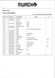
<strong>Tradesmig</strong> <strong>180</strong>−1/<strong>210</strong>−1/<strong>260</strong>−1<br />
Wear components<br />
(W. F. Mechanism 0455 890 890 / 0455 890 882)<br />
Item Denomination Ordering no. Notes<br />
A Pressure roller 0455 907 001<br />
B<br />
Feed roller<br />
0367 556 001<br />
0367 556 002<br />
0367 556 003<br />
0367 556 004<br />
Ø 0.6−0.8mm Fe, Ss, cored wire.<br />
Ø 0.8−1.0mm Fe, Ss, cored wire.<br />
Ø 1.0−1.2mm Fe, Ss, cored wire.<br />
Ø 1.0−1.2mm Al wire.<br />
C Inlet nozzle 0466 074 001<br />
D<br />
Insert tube<br />
0455 894 001<br />
0455 889 001<br />
Plastic, must be used together with item 0455 885 001,<br />
for welding with Al wire.<br />
Steel, must be used together with item 0455 886 001.<br />
E<br />
Outlet nozzle<br />
0455 885 001<br />
0455 886 001<br />
Must be used together with item 0455 894 001,<br />
for welding with Al wire.<br />
Must be used together with item 0455 889 001.<br />
The rollers are marked with wire dimension in mm, some are also marked with inch.<br />
Welding with aluminium wires.<br />
In order to weld with aluminium wires, proper rollers, nozzles and liners for<br />
aluminium wires MUST be used. It is recommended to use 3m long welding gun for<br />
aluminium wires, equipped with appropriate wear parts.<br />
wT1725<br />
− 17 −<br />
Edition050224
<strong>Tradesmig</strong> <strong>180</strong>−1/<strong>210</strong>−1/<strong>260</strong>−1<br />
Accessories<br />
Digital meter . . . . . . . . . . . . . . . . . . . . . . . . . . . . 0349 308 400<br />
Transformer kit for CO 2 heater . . . . . . . . . . . 0349 308 890<br />
aT1725<br />
− 18 −<br />
Edition 050224
hints<br />
− 19 −
hints<br />
− 20 −
hints<br />
− 21 −