k282 – tube based stereo riaa preamplifier - DIY Audio Projects
k282 – tube based stereo riaa preamplifier - DIY Audio Projects
k282 – tube based stereo riaa preamplifier - DIY Audio Projects

Create successful ePaper yourself
Turn your PDF publications into a flip-book with our unique Google optimized e-Paper software.
K282 – TUBE BASED STEREO RIAA PREAMPLIFIER<br />
NOTE: Make sure that you<br />
read and understand these<br />
notes before starting any<br />
assembly of the kit.<br />
This low cost <strong>tube</strong> <strong>preamplifier</strong> with<br />
RIAA compensation amplifies the<br />
output of a magnetic cartridge, to a<br />
Line Level required by power<br />
amplifiers etc. It is <strong>based</strong> on four<br />
low power consumption Raytheon<br />
JAN6418. These <strong>tube</strong>s were made<br />
in USA, very late in the peak of the<br />
<strong>tube</strong>-making era: Around 1980. It is<br />
interesting to know that <strong>Audio</strong><br />
Technica uses one of these <strong>tube</strong>s in<br />
its model AT3060 condenser<br />
microphone, which currently sells<br />
for around $600US.<br />
Even when used in conjunction with<br />
solid state power amplifiers,<br />
professional musicians have<br />
described <strong>tube</strong> pre-amplifiers as<br />
adding a real “richness”, and<br />
“warmth” to the sound. The warmth in<br />
this pre-amplifier can certainly not be<br />
attributed to the heat given off by the<br />
filament: Each 1.2V filament draws<br />
just 10mA! You can barely see it glow<br />
in a very dark room.<br />
ABOUT THE LIFE OF THE<br />
JAN4148 TUBES<br />
120 days ago we made a test set up<br />
using two of these <strong>tube</strong>s, which were<br />
selected from different batches...<br />
These were configured as triodes<br />
and powered continuously from a<br />
regulated 8V supply, and a regulated<br />
filament voltage of 1.3V..There has<br />
been no significant change in the<br />
anode currents of these <strong>tube</strong>s, after<br />
over the 2850 hours of operation.<br />
These are long life <strong>tube</strong>s and<br />
purchasers should not worry about<br />
having replacements!<br />
SHIELDING<br />
Almost the whole top layer of the<br />
double sided printed circuit board is<br />
grounded, so additional shielding<br />
should not be required.<br />
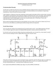
HOW IT WORKS<br />
PRE-AMPLIFIER SECTION<br />
There are two separate <strong>preamplifier</strong>s,<br />
being for the Left (CH1)<br />
and Right channels (CH2).:Since the<br />
CH1 and CH2 are identical, only CH1<br />
is described here…The input signal is<br />
applied via coupling capacitor C1 to<br />
the Grid of the Pentode <strong>tube</strong> T1. Tube<br />
T1 is configured as a Common<br />
Cathode amplifier<br />
The amplified signal at the anode of<br />
T1 is applied to the gate of FET Q1.<br />
The FET is configured as a source<br />
follower and this stage has a voltage<br />
gain of 1: This stage is a Buffer<br />
amplifier. The FET presents a<br />
negligible load to the output at the<br />
anode of T2 and therefore isolates<br />
the load from the output of T2.<br />
The signal output from the buffer<br />
amplifier is applied to the RIAA<br />
compensation network, which<br />
employs R6, R7, C3 and C4. The<br />
output from this network is applied via<br />
coupling capacitor C5 to the common<br />
cathode amplifier employing <strong>tube</strong> T2.<br />
This stage is identical to the first stage<br />
and its output is buffered by the stage<br />
associated with Q2. Finally C9<br />
couples the signal to the <strong>preamplifier</strong>s<br />
output terminals.<br />
POWER SUPPLY SECTION<br />
Each kit is supplied with a Plugpack<br />
(Wall adaptor), which provides a DC<br />
output voltage of 5V when powered<br />
from a 100-240V AC mains supply.<br />
This plugpack is supplied with a set<br />
of plugs that suit Australia, Europe,<br />
England, America, and many other<br />
countries..<br />
The power supply employs an<br />
MC34063A Switched Mode power
supply Integrated circuit. It is<br />
configured as an Up inverter and its<br />
output voltage is set at around 30V<br />
by the resistor feedback network<br />
made up by resistors R201, R202,<br />
and R203. The switching frequency<br />
is set at around 100KHz by<br />
capacitor C203.<br />
The filaments of the two <strong>tube</strong>s in<br />
each channel are connected in<br />
series. In Channel 1 series<br />
connected resistors R11 and R12<br />
limit the filament current to 10mA,<br />
from the 30V supply.<br />
CONSTRUCTION NOTES<br />
The Anode pin (1) of the <strong>tube</strong> is at<br />
the end which is marked with a red<br />
dot. This pin is inserted into the pad<br />
which is square in shape with a "1"<br />
next to the pad.<br />
PARTS LIST<br />
(SUPPLIED WITH THIS KIT)<br />
MISC.<br />
1 K282 PCB (106X84mm)<br />
4 6418 Tubes<br />
8 Grommets<br />
2 Cable Ties<br />
2 Ferrite Core Halves<br />
1M of 0.6mm diam. Enamelled<br />
Copper Wire.<br />
1 Universal 5V Power Adapter<br />
1/4W RESISTORS<br />
1 1ohm<br />
2 180ohm<br />
2 1.2Kohm<br />
2 1.5Kohm<br />
1 2.7Kohm<br />
1 5.6Kohm<br />
6 10Kohm<br />
1 56Kohm<br />
2 82Kohm<br />
6 100Kohm<br />
4 330Kohm<br />
6 1Mohm<br />
1 820ohm For Matching Tubes (See<br />
Notes)<br />
CAPACITORS<br />
1 330pF Ceramic<br />
2 6.8nF Polyester<br />
2 22nF Polyester<br />
6 100nF Polyester<br />
2 0.39uF or 0.33uF Polyester<br />
4 4.7uF 50V Electrolytic<br />
3 220uF 35V Electrolytic<br />
SEMICONDUCTORS<br />
1 IN5819 Schottky Diode<br />
4 2SK170 or BSN254A FET<br />
1 MC34063A Integrated Circuit
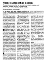
CONSTRUCTION NOTES<br />
Inductor construction<br />
Hold the two ferrite pieces<br />
together with a rubber band or<br />
something similar and apply a<br />
drop of cyanoacrylate to the<br />
center and outside joints as<br />
shown in the picture.<br />
Attach the finished inductor securely to the PCB as shown<br />
above using the cable ties supplied in the kit. Pliers may be<br />
needed to make sure the cable ties are pulled tight.<br />
Inductor shield.<br />
Solder one end of the leftover<br />
copper (as use to wind the inductor)<br />
to the point on the PCB marked<br />
SHIELD. The other end of the wire<br />
is then wrapped around the outside<br />
of the inductor 3 or 4 times. Secure<br />
the end of the wire under the cable<br />
tie as shown in the picture below.<br />
Wind the copper wire supplied<br />
around the center part of the<br />
ferrite parts fourteen times.<br />
This can be done before<br />
gluing the ferrite parts by<br />
winding the wire around a<br />
pencil then assemble and<br />
glue together. No precision is<br />
required in winding the coil.<br />
The insulating coating may<br />
need to be scraped off & the<br />
ends tinned with solder before<br />
fitting the inductor to the PCB.<br />
MICROPHONIC TUBE<br />
The <strong>tube</strong> used in this kit like all<br />
other <strong>tube</strong>s is microphonic. And will<br />
"ring" if struck. For best results<br />
Rubber grommets can be fitted to<br />
the <strong>tube</strong>s to greatly reduce /<br />
eliminate the ringing. The grommets<br />
supplied fit tightly and are easier to<br />
instal if they are moistened first.<br />
Pin 1<br />
Red mark.
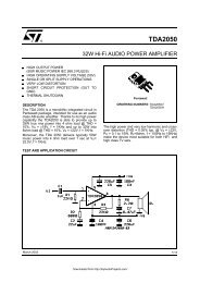
TUBE/VALVE MATCHING (For the purists)<br />
Every <strong>tube</strong> of the same part number, will produce a<br />
different gain, even when used in the same<br />
configuration. It is possible to get a better overalll<br />
gain balance between the two channels, by<br />
estimating the gain of each of the <strong>tube</strong>s supplied. If<br />
one wishes to better match the gain, measure the<br />
current using the test circuit shown below, note that<br />
the 820 ohm resistor is supplied in the kit. Then from<br />
the graph provided estimate the gain that each of<br />
the <strong>tube</strong>s would provide. and write it on the <strong>tube</strong><br />
box. Each of the channels has two cascaded stages<br />
so the overall gain is dependent of the multiple of<br />
the gains of the two <strong>tube</strong>s used. From the <strong>tube</strong>s<br />
tested choose two pairs that will give a similar gain<br />
in each of the channels.<br />
CURRENT<br />
METER<br />
GAIN (AV.)<br />
12<br />
9<br />
6<br />
3<br />
I<br />
uA<br />
50 100 150