
Create successful ePaper yourself
Turn your PDF publications into a flip-book with our unique Google optimized e-Paper software.
<strong>Decod<strong>in</strong>g</strong> <strong>in</strong> <strong>Analog</strong> <strong>VLSI</strong><br />
Hans-Andrea Loeliger and Felix Tarköy, Endora Tech AG<br />
Felix Lustenberger and Markus Helfenste<strong>in</strong>, ETH Zurich<br />
ABSTRACT<br />
A<br />
dvanced error correct<strong>in</strong>g codes and/or coded<br />
modulation schemes are an essential part of most<br />
modern data transmission systems for both wireless and copper<br />
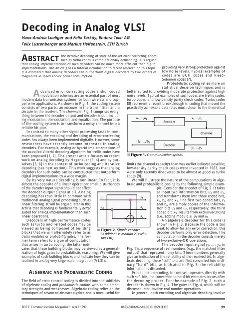
wire applications. As shown <strong>in</strong> Fig. 1, the cod<strong>in</strong>g system<br />
consists of two parts: an encoder <strong>in</strong> the transmitter and a<br />
decoder <strong>in</strong> the receiver. The channel <strong>in</strong> Fig. 1 comprises everyth<strong>in</strong>g<br />
between the encoder output and decoder <strong>in</strong>put, <strong>in</strong>clud<strong>in</strong>g<br />
modulation, demodulation, and equalization. The purpose<br />
of the cod<strong>in</strong>g system is to transform a noisy channel <strong>in</strong>to a<br />
reliable bit pipe.<br />
In contrast to many other signal process<strong>in</strong>g tasks <strong>in</strong> communications,<br />
the encod<strong>in</strong>g and decod<strong>in</strong>g of error-correct<strong>in</strong>g<br />
codes has always been implemented digitally. However, some<br />
researchers have recently become <strong>in</strong>terested <strong>in</strong> analog<br />
decoders. For example, analog or hybrid implementations of<br />
the so-called Viterbi decod<strong>in</strong>g algorithm for trellis codes have<br />
been proposed [1, 2]. The present article focuses on recent<br />
work on analog decod<strong>in</strong>g by Hagenauer [3, 4] and by ourselves<br />
[5, 6] <strong>in</strong> the context of turbo cod<strong>in</strong>g and iterative<br />
decod<strong>in</strong>g (see next section). This work suggests that analog<br />
decoders for such codes can be constructed that outperform<br />
digital implementations by a wide marg<strong>in</strong>.<br />
By its very nature decod<strong>in</strong>g is nonl<strong>in</strong>ear. In fact, it is<br />
almost the opposite of a l<strong>in</strong>ear operation: small disturbances<br />
of the decoder <strong>in</strong>put signal should not affect<br />
the decoder output signal at all. <strong>Analog</strong><br />
The iterative decod<strong>in</strong>g of state-of-the-art error correct<strong>in</strong>g codes<br />
such as turbo codes is computationally demand<strong>in</strong>g. It is argued<br />
that analog implementations of such decoders can be much more efficient than digital<br />
implementations. This article gives a tutorial <strong>in</strong>troduction to recent research on this topic.<br />
It is estimated that analog decoders can outperform digital decoders by two orders of<br />
magnitude <strong>in</strong> speed and/or power consumption.<br />
decod<strong>in</strong>g has thus little <strong>in</strong> common with<br />
traditional analog signal process<strong>in</strong>g such as<br />
l<strong>in</strong>ear filter<strong>in</strong>g. It will be argued later <strong>in</strong> this<br />
article that decod<strong>in</strong>g is fundamentally better<br />
suited for analog implementation than such<br />
l<strong>in</strong>ear operations.<br />
Decoders of high-performance codes<br />
such as turbo and related codes may be<br />
viewed as be<strong>in</strong>g composed of build<strong>in</strong>g<br />
blocks that we will alternately refer to as<br />
trellis modules or probability gates. The former<br />
term refers to a type of computation<br />
that arises <strong>in</strong> turbo cod<strong>in</strong>g; the latter <strong>in</strong>dicates<br />
that these build<strong>in</strong>g blocks may be viewed as a generalization<br />
of logic gates to probabilistic reason<strong>in</strong>g. We will give<br />
examples of such build<strong>in</strong>g blocks and <strong>in</strong>dicate how they can be<br />
realized <strong>in</strong> analog very large-scale <strong>in</strong>tegration (<strong>VLSI</strong>).<br />
ALGEBRAIC AND PROBABILISTIC CODING<br />
The field of error control cod<strong>in</strong>g is divided <strong>in</strong>to the subfields<br />
of algebraic cod<strong>in</strong>g and probabilistic cod<strong>in</strong>g, with complementary<br />
strengths and weaknesses. Algebraic cod<strong>in</strong>g relies on the<br />
techniques of advanced abstract algebra and is most useful for<br />
provid<strong>in</strong>g very strong protection aga<strong>in</strong>st<br />
low noise levels. Typical examples of<br />
codes are BCH codes and Reed-<br />
Solomon codes [7].<br />
Probabilistic cod<strong>in</strong>g relies more on<br />
statistical decision techniques and is<br />
better suited to provid<strong>in</strong>g moderate protection aga<strong>in</strong>st high<br />
noise levels. Typical examples of such codes are trellis codes,<br />
turbo codes, and low-density parity check codes. Turbo codes<br />
[8] represent a recent breakthrough <strong>in</strong> cod<strong>in</strong>g that moved the<br />
practically achievable data rates much closer to the theoretical<br />
u 1 ,...,u k<br />
u 1 x 1<br />
u 2 x 2<br />
^u 1 ,...,^u k<br />
■ Figure 1. Communication system.<br />
limit (the channel capacity) than was earlier believed possible;<br />
low-density parity check codes were <strong>in</strong>vented <strong>in</strong> 1963, but<br />
were only recently discovered to be almost as good as turbo<br />
codes [9].<br />
We will illustrate the nature of the computations <strong>in</strong> algebraic<br />
and probabilistic cod<strong>in</strong>g by the follow<strong>in</strong>g simple example.<br />
Consider the encoder of Fig. 2. It takes<br />
as <strong>in</strong>put two <strong>in</strong>formation bits, u 1 and u 2 ,<br />
x 3<br />
■ Figure 2. Simple encoder.<br />
“Addition” is modulo 2 (exclusive<br />
OR).<br />
Encoder<br />
Decoder<br />
x 1 ,...,x n<br />
y 1 ,...,y n<br />
Channel<br />
and transforms them <strong>in</strong>to three coded bits,<br />
x 1 , x 2 , and x 3 . The first two coded bits, x 1<br />
and x 2 , are simply copies of the <strong>in</strong>formation<br />
bits u 1 and u 2 , respectively; the third<br />
coded bit, x 3 , results from exclusive-OR<strong>in</strong>g<br />
(i.e., add<strong>in</strong>g modulo 2) u 1 and u 2 .<br />
An algebraic decoder for this code is<br />
shown <strong>in</strong> Fig. 3. Because the code is too<br />
weak to allow for any error correction, this<br />
decoder performs only error detection. The<br />
computation <strong>in</strong> the decoder consists merely<br />
of two exclusive-OR operations.<br />
The decoder <strong>in</strong>put signal y 1 , …, y n <strong>in</strong><br />
Fig. 1 is a sequence of real numbers (e.g., the matched filter<br />
output) that represent noisy bits. These numbers generally<br />
give an <strong>in</strong>dication of the reliability of the received bit. In algebraic<br />
decod<strong>in</strong>g, these “soft” bits are first converted <strong>in</strong>to ord<strong>in</strong>ary<br />
“hard” bits, as <strong>in</strong>dicated <strong>in</strong> Fig. 3; the reliability<br />
<strong>in</strong>formation is discarded.<br />
Probabilistic decod<strong>in</strong>g, <strong>in</strong> contrast, operates directly with<br />
such soft bits; the conversion to hard bit estimates occurs after<br />
the decod<strong>in</strong>g proper. For the example of Fig. 2, such a<br />
decoder is shown <strong>in</strong> Fig. 4. The gates <strong>in</strong> Fig. 4, which will be<br />
discussed later, <strong>in</strong>volve real number operations.<br />
In general, both encod<strong>in</strong>g and algebraic decod<strong>in</strong>g <strong>in</strong>volve<br />
IEEE Communications Magaz<strong>in</strong>e • April 1999<br />
0163-6804/99/$10.00 © 1999 IEEE<br />
99
y 1<br />
^u1<br />
y 1<br />
~ u1 ^u1<br />
y 2<br />
y 3<br />
■ Figure 3. Error detection for the code of Fig. 2.<br />
mostly exclusive-OR operations, which are perfectly suited for<br />
digital implementation. Probabilistic decod<strong>in</strong>g, on the other<br />
hand, uses computations with real numbers, which makes digital<br />
implementations of such decoders much more complex<br />
than those of algebraic decoders.<br />
Moreover, the computation networks of decoders for<br />
high-performance codes such as turbo codes and low-density<br />
parity check codes conta<strong>in</strong> loops. In digital implementations,<br />
these loops lead to iterative computations where the whole<br />
network is recomputed several times until a steady state is<br />
reached (or until the available time is over). Such iterations<br />
are also required if the soft output of the decoder is fed back<br />
to other parts of the receiver, as <strong>in</strong>dicated <strong>in</strong> Fig. 5. (The use<br />
of such feedback loops is the subject of much current<br />
research.) The comb<strong>in</strong>ed needs of real-number arithmetic<br />
and iterative decod<strong>in</strong>g require substantial computational<br />
resources.<br />
Graphical representations of codes and decod<strong>in</strong>g networks<br />
as <strong>in</strong> Fig. 4 have recently become a subject of significant<br />
research <strong>in</strong>terest [10–13].<br />
^u2<br />
Error detection flag<br />
y 2<br />
y 3<br />
~ u2 ^u2<br />
■ Figure 4. <strong>Decod<strong>in</strong>g</strong> with “probability gates.”<br />
THE IMPLEMENTATION OF<br />
PROBABILITY GATES<br />
We now describe the operation and implementation of the<br />
two types of probability gates <strong>in</strong> Fig. 4. As we will see, the<br />
description of these operations depends strongly on the representation<br />
used for the soft bits. We beg<strong>in</strong> with the follow<strong>in</strong>g<br />
representation. Each soft bit is represented by two nonnegative<br />
real numbers, p(0) and p(1), that add up to one. The<br />
value p(0) is (or is <strong>in</strong>terpreted as) the probability that the bit<br />
is zero; p(1) is (or is <strong>in</strong>terpreted as) the probability that the<br />
bit is one. For this representation, the two gate types of Fig. 4<br />
are def<strong>in</strong>ed as <strong>in</strong> Fig. 6. The scale factor γ <strong>in</strong> Fig. 6 is chosen<br />
such that p 3 (0) + p 3 (1) = 1.<br />
The two gate types of Fig. 6 suffice for low-density parity<br />
check codes; they do not suffice for trellis codes and turbo<br />
codes. The additional trellis modules that are needed for the<br />
latter codes also <strong>in</strong>volve nonb<strong>in</strong>ary states.<br />
DIGITAL VS. ANALOG: FUNDAMENTALS<br />
The very idea of chang<strong>in</strong>g from digital to analog will probably<br />
appear odd to most readers. The problems commonly associated<br />
with analog signal process<strong>in</strong>g <strong>in</strong>clude sensitivity to component<br />
variations, susceptibility to noise and power supply<br />
disturbances, and temperature dependency, among others.<br />
However, the work by Mead [14] and others on neuromorphic<br />
analog <strong>VLSI</strong> has demonstrated that analog signal process<strong>in</strong>g<br />
systems can be built that share the robustness of digital systems<br />
but outperform digital systems by several orders<br />
of magnitude <strong>in</strong> terms of speed and/or power consumption.<br />
This approach is characterized by exploit<strong>in</strong>g,<br />
rather than fight<strong>in</strong>g, the fundamental nonl<strong>in</strong>earities of<br />
transistor physics and by system designs that achieve<br />
global accuracy despite imprecise local subsystems and<br />
components.<br />
The <strong>in</strong>herent nature of decod<strong>in</strong>g makes it attractive<br />
for such an approach. <strong>Decod<strong>in</strong>g</strong> operates on noisy signals<br />
that are gradually transformed <strong>in</strong>to “clean” bits;<br />
s<strong>in</strong>ce the <strong>in</strong>put signals are noisy anyway, they need not<br />
be represented and processed with high precision. On<br />
the other hand, a large dynamic range is required,<br />
which can be provided by a suitable analog design.<br />
Also, analog process<strong>in</strong>g with cont<strong>in</strong>uous-time networks<br />
elim<strong>in</strong>ates the iterations mentioned <strong>in</strong> the previous<br />
section, which are replaced by the settl<strong>in</strong>g behavior of<br />
the network.<br />
<strong>Decod<strong>in</strong>g</strong> networks (as <strong>in</strong> Fig. 4) typically conta<strong>in</strong><br />
only a small number of different types of trellis modules<br />
(probability gates). This means that the design of<br />
such decod<strong>in</strong>g networks <strong>in</strong> analog <strong>VLSI</strong> is similar <strong>in</strong><br />
spirit to the design of digital networks with logic gates.<br />
Moreover, <strong>in</strong> the approach of [6], all module types can<br />
be realized as variations of the same simple transistor<br />
circuit.<br />
u 1 ,...,u k<br />
^u 1 ,...,^u k<br />
LOG-LIKELIHOOD-RATIO REPRESENTATION<br />
An alternative representation of a soft bit is the s<strong>in</strong>gle number<br />
L = log(p(0)/p(1)), which is commonly referred to as the loglikelihood<br />
ratio. In this representation, the operation of the<br />
“equals-sign” gate (right <strong>in</strong> Fig. 6) becomes simple addition:<br />
L 3 = L 1 + L 2 . The “soft-EXOR” gate (left <strong>in</strong> Fig. 6) is<br />
expressed by the formula L 3 = 2 tanh –1 (tanh(L 1 /2)<br />
tanh(L 2 /2)), which is illustrated <strong>in</strong> Fig. 7.<br />
Hagenauer’s approach to analog decod<strong>in</strong>g is based on this<br />
log-likelihood representation and on realiz<strong>in</strong>g these two for-<br />
Encoder<br />
Decoder<br />
Channel<br />
■ Figure 5. Soft feedback from decoder to equalizer.<br />
p 1 (.)<br />
p 2 (.)<br />
p 3 (.)<br />
p 3 (0) = p 1 (0)p 2 (0) + p 1 (1)p 2 (1)<br />
p 3 (1) = p 1 (0)p 2 (1) + p 1 (1)p 2 (0)<br />
■ Figure 6. The “probability gates” from Fig. 4.<br />
p 2 (.)<br />
Equalizer<br />
p 1 (.) p 3 (.)<br />
p 3 (0) = γ p 1 (0)p 2 (0)<br />
p 3 (1) = γ p 1 (1)p 2 (1)<br />
100<br />
IEEE Communications Magaz<strong>in</strong>e • April 1999
L 1<br />
l 3 p 3 (0) l 3 p 3 (1)<br />
L 2<br />
L 3<br />
l 2 p 2 (0)<br />
l 2 p 2 (1)<br />
■ Figure 7. Soft-exclusive-OR gate for log-likelihoodratio<br />
representation.<br />
l 1 p 1 (0)<br />
l 1 p 1 (1)<br />
mulas as analog circuits. A number of simulations<br />
with ideal analog cells of this type have been reported.<br />
These simulations show that cont<strong>in</strong>uous-time<br />
decod<strong>in</strong>g with networks as <strong>in</strong> Fig. 4 can work well<br />
even if the network has loops. Transistor-level circuits<br />
have not yet been reported.<br />
CURRENT-VECTOR REPRESENTATION<br />
Our own approach, <strong>in</strong> contrast, is based on represent<strong>in</strong>g each<br />
soft bit by two currents, I·p(0) and I·p(1), where the sum current<br />
I can be chosen freely. This representation has the advantage<br />
that all signals/currents are unipolar and cannot overflow.<br />
Moreover, it has led to a large family of simple transistor circuits<br />
for essentially all trellis modules (even with nonb<strong>in</strong>ary<br />
states) that are of <strong>in</strong>terest <strong>in</strong> cod<strong>in</strong>g [6].<br />
The correspond<strong>in</strong>g circuit for the soft-EXOR gate (left<br />
<strong>in</strong> Fig. 6) is shown <strong>in</strong> Fig. 8. The transistors are assumed to<br />
operate <strong>in</strong> so-called subthreshold mode; alternatively, bipolar<br />
transistors can be used. The particular circuit of Fig. 8<br />
happens to be (a version of) the so-called Gilbert multiplier,<br />
which is a standard circuit for real number multiplication;<br />
that it is, <strong>in</strong> fact, an exact soft-EXOR seems not to have<br />
been noticed before. The correspond<strong>in</strong>g circuit for the<br />
equals-sign gate differs from Fig. 8 only <strong>in</strong> a slight change <strong>in</strong><br />
the wir<strong>in</strong>g.<br />
We have made extensive transistor-level simulations with<br />
decod<strong>in</strong>g networks of such modules, and a work<strong>in</strong>g proof-ofconcept<br />
chip has been manufactured. We found that such<br />
decod<strong>in</strong>g networks work very well and are robust aga<strong>in</strong>st the<br />
nonidealities of real transistors. From this experience, we<br />
expect that such decoders will outperform digital implementations<br />
by two orders of magnitude <strong>in</strong> terms of speed (when<br />
designed for the same power level) or power consumption<br />
(when designed for the same speed).<br />
■ Figure 8. Soft-exclusive-OR gate for current-vector representation.<br />
[4] J. Hagenauer, “<strong>Decod<strong>in</strong>g</strong> of B<strong>in</strong>ary Codes with <strong>Analog</strong> Networks,” Proc.<br />
1998 Info. Theory Wksp., San Diego, CA, Feb. 8–11, 1998, pp. 13–14.<br />
[5] M. Helfenste<strong>in</strong> et al., “Verfahren und Schaltung zur Signalverarbeitung,<br />
<strong>in</strong>sbesondere zur Berechnung e<strong>in</strong>er Wahrsche<strong>in</strong>lichkeitsfunktion,” Swiss<br />
Pat. Appl. no. 1998 0375/98, Feb. 17, 1998.<br />
[6] H.-A. Loeliger et al., “Probability Propagation and <strong>Decod<strong>in</strong>g</strong> <strong>in</strong> <strong>Analog</strong><br />
<strong>VLSI</strong>,” Proc. 1998 IEEE Int’l. Symp. Info. Theory, Cambridge, MA, Aug.<br />
16–21, 1998, p. 146.<br />
[7] R. E. Blahut, Theory and Practice of Error Control Codes, Addison-Wesley,<br />
1984.<br />
[8] C. Berrou, A. Glavieux, and P. Thitimajshima, “Near Shannon-limit errorcorrect<strong>in</strong>g<br />
cod<strong>in</strong>g and decod<strong>in</strong>g: turbo codes,” Proc. ICC ’93, Geneva,<br />
Switzerland, May 1993, pp. 1064–70.<br />
[9] D. J. C. MacKay and R. M. Neal, “Good codes based on very sparse matrices,”<br />
Cryptography and Cod<strong>in</strong>g. 5th <strong>IMA</strong> Conf.,C. Boyd, Ed., no. 1025,<br />
Lecture Notes <strong>in</strong> Computer Science, Berl<strong>in</strong>: Spr<strong>in</strong>ger, 1995, pp. 100–11.<br />
[10] N. Wiberg, “Codes and <strong>Decod<strong>in</strong>g</strong> on General Graphs,” Ph.D. thesis,<br />
Univ. L<strong>in</strong>köp<strong>in</strong>g, Sweden, 1996.<br />
[11] B. J. Frey, Graphical Models for Mach<strong>in</strong>e Learn<strong>in</strong>g and Digital Communications,<br />
Cambridge, MA: MIT Press, 1998.<br />
[12] G. D. Forney, Jr., “The forward-backward algorithm,” Proc. 34th Allerton<br />
Conf. Commun., Control, and Comp., Monticello, IL: Allerton<br />
House, Oct. 2–4, 1996, pp. 432–46.<br />
[13] B. J. Frey et al., “Factor graphs and algorithms,” Proc. 35th Allerton<br />
Conf. Commun., Control, and Comp., Monticello, IL: Allerton House,<br />
Sept. 29–Oct. 1, 1997, pp. 666–80.<br />
[14] C. Mead, <strong>Analog</strong> <strong>VLSI</strong> and Neural Systems, Addison-Wesley, 1989.<br />
BIOGRAPHIES<br />
HANS-ANDREA LOELIGER (haloeliger@endora.ch) is a consultant <strong>in</strong> signal process<strong>in</strong>g,<br />
digital communications, and error-correct<strong>in</strong>g codes. He received a<br />
diploma <strong>in</strong> electrical eng<strong>in</strong>eer<strong>in</strong>g from the Swiss Federal Institute of Technology<br />
(ETH), Zurich, Switzerland, <strong>in</strong> 1985 and a Ph.D. degree, also from<br />
ETH Zurich, <strong>in</strong> 1992. From 1992 to 1995 he was assistant professor at<br />
L<strong>in</strong>köp<strong>in</strong>g University, Sweden. He is now with Endora Tech AG, Basel,<br />
Switzerland, which he co-founded <strong>in</strong> 1995.<br />
CONCLUSIONS<br />
We have described recent research results on analog <strong>VLSI</strong><br />
decod<strong>in</strong>g networks for error correct<strong>in</strong>g codes. Such decoders<br />
appear attractive for applications where speed and/or power<br />
consumption are critical; the expected ga<strong>in</strong>s amount to two<br />
orders of magnitude. The versatile new “probability gates” are<br />
likely to be useful beyond decod<strong>in</strong>g.<br />
REFERENCES<br />
[1] M. H. Shakiba, D. A. Johns, and K. W. Mart<strong>in</strong>, “BiCMOS Circuits for <strong>Analog</strong><br />
Viterbi Decoders,” IEEE Trans. Circuits and Sys. II, vol. 45, Dec.<br />
1998, pp. 1527–37.<br />
[2] X. Wang and S. B. Wicker, “An artificial neural net Viterbi decoder,”<br />
IEEE Trans. Commun., vol. 44, Feb. 1996, pp. 165–71.<br />
[3] J. Hagenauer, “Der <strong>Analog</strong>e Dekoder,” German Pat. Appl. no. 197 25<br />
275.3, filed June 14, 1997.<br />
FELIX LUSTENBERGER (lustenbe@isi.ee.ethz.ch) received his diploma (M.Sc.) <strong>in</strong><br />
micro eng<strong>in</strong>eer<strong>in</strong>g from the Swiss Federal Institute of Technology (EPFL),<br />
Lausanne, Switzerland, <strong>in</strong> 1995. Currently he is a research assistant at the<br />
Signal and Information Process<strong>in</strong>g Laboratory of ETH Zurich, Switzerland,<br />
where he is work<strong>in</strong>g toward his Ph.D. degree <strong>in</strong> electrical eng<strong>in</strong>eer<strong>in</strong>g. His<br />
ma<strong>in</strong> research <strong>in</strong>terests are <strong>in</strong> analog and neuromorphic <strong>VLSI</strong> design.<br />
FELIX TARKÖY (ftarkoey@endora.ch) is a consultant <strong>in</strong> multi-user communications,<br />
signal process<strong>in</strong>g, and error-control cod<strong>in</strong>g. He received a diploma<br />
(M.Sc.) and a Ph.D. degree from the Swiss Federal Institute of Technology<br />
(ETH), Zurich, Switzerland, <strong>in</strong> 1987 and 1994, respectively. From 1987–1989<br />
he worked for Ascom Tech AG <strong>in</strong> Solothurn, Switzerland. He is now with<br />
Endora Tech AG, Basel, Switzerland, which he co-founded <strong>in</strong> 1995.<br />
MARKUS HELFENSTEIN (helfenst@isi.ee.ethz.ch) received a diploma (M.Sc.) and<br />
a Ph.D. degree <strong>in</strong> electrical eng<strong>in</strong>eer<strong>in</strong>g from the Swiss Federal Institute of<br />
Technology (ETH), Zurich, Switzerland, <strong>in</strong> 1992 and 1997, respectively.<br />
From 1986 to 1988, he worked as an IC designer for Mettler Instrumente<br />
AG <strong>in</strong> Zurich, Switzerland. He is now a senior assistant at ETH Zurich. His<br />
scientific <strong>in</strong>terest is <strong>in</strong> analog <strong>in</strong>tegrated circuit design, <strong>in</strong>clud<strong>in</strong>g sampleddata<br />
filters, high-speed op-amps, and analog decod<strong>in</strong>g techniques for <strong>VLSI</strong>.<br />
IEEE Communications Magaz<strong>in</strong>e • April 1999 101