You also want an ePaper? Increase the reach of your titles
YUMPU automatically turns print PDFs into web optimized ePapers that Google loves.
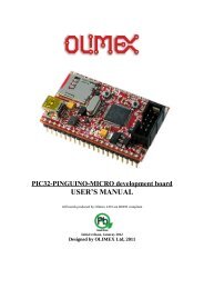
<strong>Arduino</strong> <strong>Energy</strong> <strong>Shield</strong><br />
User’s Manual<br />
Rev. A<br />
MCI-MA-0087<br />
MCI Electronics<br />
www.olimex.cl<br />
Luis Thayer Ojeda 0115. Of. 402 ▪ Santiago, Chile ▪ Tel. +56 2 3339579 ▪ info@olimex.cl
MCI Ltda.<br />
Luis Thayer Ojeda 0115. Of. 402<br />
Santiago, Chile<br />
www.olimex.cl<br />
Tel: +56 2 3339579<br />
Fax: +56 2 3350589<br />
® MCI Ltda. 2011<br />
Attention: Any changes and modifications done to the device will void its warranty<br />
unless expressly authorized by MCI.<br />
Manual Code: MCI – MA - 0087
<strong>Arduino</strong> <strong>Energy</strong> <strong>Shield</strong> User’s Manual Page 3 of 16<br />
CONTENTS<br />
CONTENTS ............................................................................................................ 3<br />
INTRODUCTION .................................................................................................... 4<br />
GENERAL FEATURES ........................................................................................... 5<br />
DEFINITIONS ......................................................................................................... 5<br />
SHIELD PARTS ...................................................................................................... 6<br />
SHIELD INSTALLATION ......................................................................................... 8<br />
PORT MAPPING .................................................................................................. 10<br />
ELECTRICAL CHARACTERISTICS ..................................................................... 10<br />
MECHANICAL CHARACTERISTICS .................................................................... 10<br />
REAL TIME CLOCK CONFIGURATION ............................................................... 11<br />
ENERGY SENSING .............................................................................................. 12<br />
NOTES ................................................................................................................. 15<br />
MAINTENANCE .................................................................................................... 15<br />
DOCUMENT HISTORY ........................................................................................ 16<br />
Luis Thayer Ojeda 0115 Of. 402 ▪ Santiago, Chile ▪ Tel. +56 2 3339579 ▪ info@olimex.cl<br />
www.olimex.cl
<strong>Arduino</strong> <strong>Energy</strong> <strong>Shield</strong> User’s Manual Page 4 of 16<br />
INTRODUCTION<br />
<strong>Arduino</strong> <strong>Energy</strong> <strong>Shield</strong> is a board which enables you to monitor your house, office,<br />
installation or any other equipment energy consumption, directly with your <strong>Arduino</strong><br />
board, without the need of wiring, using the XBee wireless communication link. <strong>Arduino</strong><br />
<strong>Energy</strong> <strong>Shield</strong> integrates the ADE7753 chip which allows to sense active power,<br />
reactive power, RMS voltage and current, among other variables, at a given time.<br />
<strong>Arduino</strong> <strong>Energy</strong> <strong>Shield</strong> is compatible with <strong>Arduino</strong> Duemilanove, Uno and Mega<br />
boards.<br />
The <strong>Arduino</strong> <strong>Energy</strong> <strong>Shield</strong> has an embedded real time clock, which allows adding the<br />
date and time to the sensed data and sending it to another device for its post<br />
processing and visualization. It also has a coin type battery socket, as a backup power<br />
supply for the real time clock.<br />
The <strong>Arduino</strong> <strong>Energy</strong> <strong>Shield</strong> also has an onboard socket for XBee/XBee Pro, for<br />
transmitting data to other devices, without the need of wiring from the sensing place to<br />
the storage, processing and visualization equipment of the data sensed by the <strong>Arduino</strong><br />
<strong>Energy</strong> <strong>Shield</strong>.<br />
The <strong>Arduino</strong> <strong>Energy</strong> <strong>Shield</strong> comes with complete function libraries, useful to make any<br />
kind of operations with the probes, like calibration tasks or getting the sensed data.<br />
Function Libraries for communication with the real time clock are also included.<br />
Luis Thayer Ojeda 0115 Of. 402 ▪ Santiago, Chile ▪ Tel. +56 2 3339579 ▪ info@olimex.cl<br />
www.olimex.cl
<strong>Arduino</strong> <strong>Energy</strong> <strong>Shield</strong> User’s Manual Page 5 of 16<br />
GENERAL FEATURES<br />
Active and apparent power measurement.<br />
RMS voltage and current measurement.<br />
Operation range from 0[V] to 220[V].<br />
30[A] maximum current.<br />
Temperature sensor measurement range from -25°C to 80°C, with 3°C<br />
precision.<br />
Sensor input<br />
o Voltage input: 12VAC<br />
o Current input: 20mA max.<br />
Opto-isolated pulse output, with frequency proportional to watt-hour<br />
measurements.<br />
12mm Coin type battery socket.<br />
Real time clock.<br />
o IC DS1307.<br />
o 32kHz clock.<br />
<strong>Arduino</strong> reset button.<br />
5 V DC power supply.<br />
XBee/XBee Pro socket.<br />
Galvanically isolated probe connectors.<br />
DEFINITIONS<br />
RSSI: Receive Signal Strength Indicator.<br />
XBee: 2.4 GHz wireless communication module. It supports point-to-point,<br />
point-to-multipoint and mesh networks.<br />
Real Time Clock (RTC): Exact time counter integrated circuit. The RTC<br />
included with the <strong>Arduino</strong> <strong>Energy</strong> <strong>Shield</strong> gives both the time and date, among other<br />
features that can be accessed with the included function library.<br />
Pulse output: Old analog sensors had a rotating wheel: a certain amount of<br />
turns represented 1kWh. In <strong>Arduino</strong> <strong>Energy</strong> <strong>Shield</strong> this feature is still available due<br />
to the pulse output feature, which is optically connected to the internal circuitry.<br />
Luis Thayer Ojeda 0115 Of. 402 ▪ Santiago, Chile ▪ Tel. +56 2 3339579 ▪ info@olimex.cl<br />
www.olimex.cl
<strong>Arduino</strong> <strong>Energy</strong> <strong>Shield</strong> User’s Manual Page 6 of 16<br />
SHIELD PARTS<br />
Pulse LED<br />
XBee<br />
module<br />
LED RSSI<br />
Pulse<br />
output<br />
LED<br />
Data in<br />
LED<br />
Data out<br />
Battery<br />
socket<br />
Reset<br />
button<br />
Fig.1 <strong>Arduino</strong> <strong>Energy</strong> <strong>Shield</strong> top view.<br />
Voltage<br />
probe<br />
Current<br />
probe<br />
XBee module: XBee socket for its installation.<br />
LED RSSI: XBee module Received Signal Strength Indicator LED.<br />
LED Data in: Data received LED indicator. If it is on, the XBee module is<br />
receiving data.<br />
LED Data out: Data transferred LED indicator. If it is on, the XBee module<br />
is transmitting data.<br />
Battery socket: Coin type Lithium battery socket. Its main functionality is<br />
to maintain the real time clock on, even if the board is de-energized.<br />
Reset: <strong>Arduino</strong> reset button.<br />
Pulse LED: LED which blinks with a frequency proportional to the<br />
consumption. This frequency depends on the constant parameter set in the<br />
probe. The <strong>Arduino</strong> <strong>Energy</strong> <strong>Shield</strong> gives 32000 pulses/kWh.<br />
LED PWR: Energized board LED indicator.<br />
o<br />
On: Energized board.<br />
Luis Thayer Ojeda 0115 Of. 402 ▪ Santiago, Chile ▪ Tel. +56 2 3339579 ▪ info@olimex.cl<br />
www.olimex.cl
<strong>Arduino</strong> <strong>Energy</strong> <strong>Shield</strong> User’s Manual Page 7 of 16<br />
o<br />
Off: De-energized board.<br />
Pulse output: Opto-isolated output. It can be used for calibration or to do<br />
monitoring tasks.<br />
Voltage probe: Voltage probe terminal block connector 12VAC.<br />
Current Probe: Current probe terminal block connector. The module was<br />
designed to be used with a 20mA max. non-invasive AC current sensor<br />
which works by sensing the electromagnetic generated by the current flow<br />
in a conductor. This is why it is not necessary to interrupt the circuit for<br />
measurements.<br />
Luis Thayer Ojeda 0115 Of. 402 ▪ Santiago, Chile ▪ Tel. +56 2 3339579 ▪ info@olimex.cl<br />
www.olimex.cl
<strong>Arduino</strong> <strong>Energy</strong> <strong>Shield</strong> User’s Manual Page 8 of 16<br />
SHIELD INSTALLATION<br />
To connect the <strong>Arduino</strong> <strong>Energy</strong> <strong>Shield</strong> to the base board (Duemilanove, Mega<br />
or Uno), a few steps must be followed:<br />
A. Place the XBee radio on its socket, according to the silkscreen<br />
orientation.<br />
B. Insert the Coin type Lithium battery in its socket.<br />
C. Connect the current probe to the corresponding terminals.<br />
D. Connect the voltage probe to the corresponding terminals.<br />
E. Place the shield over the <strong>Arduino</strong> main board as shown in figure 2. It is<br />
important to mention that the pin headers that connect the shield with<br />
<strong>Arduino</strong> have only one position.<br />
F. Assemble the <strong>Arduino</strong> <strong>Energy</strong> <strong>Shield</strong> with the <strong>Arduino</strong> main board.<br />
G. Connect the <strong>Arduino</strong> main board to the PC by using a USB cable.<br />
Luis Thayer Ojeda 0115 Of. 402 ▪ Santiago, Chile ▪ Tel. +56 2 3339579 ▪ info@olimex.cl<br />
www.olimex.cl
<strong>Arduino</strong> <strong>Energy</strong> <strong>Shield</strong> User’s Manual Page 9 of 16<br />
D<br />
C<br />
A<br />
F<br />
E<br />
B<br />
G<br />
Fig.2 <strong>Arduino</strong> <strong>Energy</strong> <strong>Shield</strong> assembly.<br />
Luis Thayer Ojeda 0115 Of. 402 ▪ Santiago, Chile ▪ Tel. +56 2 3339579 ▪ info@olimex.cl<br />
www.olimex.cl
<strong>Arduino</strong> <strong>Energy</strong> <strong>Shield</strong> User’s Manual Page 10 of 16<br />
PORT MAPPING<br />
The I/O ports used by the <strong>Arduino</strong> <strong>Energy</strong> <strong>Shield</strong> can’t be used by another<br />
shield, with the exception of SDA, SCL and RESET signals.<br />
Pin Name Function<br />
DIGITAL 0 Serial RX Hardware connection to Rx Serial Port pin. Not<br />
used.<br />
DIGITAL 1 Serial TX Hardware connection to Tx Serial Port pin. Not<br />
used.<br />
DIGITAL 2 SoftSerial RX Software connection to Rx Serial Port pin.<br />
DIGITAL 3 SoftSerial TX Software connection to Tx Serial Port pin.<br />
DIGITAL 10 CHIP SELECT For enabling probe communication.<br />
DIGITAL 11 DATA IN Probe communication input data.<br />
DIGITAL 12 DATA OUT Probe communication output data.<br />
DIGITAL 13 SIGNAL CLOCK Probe communication clock signal.<br />
ANALOG 4 I2C RTC SDA I 2 C clock communication data.<br />
ANALOG 5 I2C RTC SCL I 2 C clock communication signal.<br />
ELECTRICAL CHARACTERISTICS<br />
5 V DC power supply.<br />
12mm 3V Coin type battery socket.<br />
Average consumption: 5.4mA without XBee module, 52.4mA with<br />
connected XBee module.<br />
MECHANICAL CHARACTERISTICS<br />
Dimensions (WidthxLengthxHeight) 54x69x12 [mm]<br />
Luis Thayer Ojeda 0115 Of. 402 ▪ Santiago, Chile ▪ Tel. +56 2 3339579 ▪ info@olimex.cl<br />
www.olimex.cl
<strong>Arduino</strong> <strong>Energy</strong> <strong>Shield</strong> User’s Manual Page 11 of 16<br />
REAL TIME CLOCK CONFIGURATION<br />
To configure the <strong>Arduino</strong> <strong>Energy</strong> <strong>Shield</strong> real time clock, the <strong>Arduino</strong> sketch<br />
“Configure.pde” has to be used. You can download it from the product’s website at<br />
http://www.olimex.cl.<br />
When running the sketch, the command line will ask for the actual date first, and<br />
then for the time. These parameters will be used to configure the clock.<br />
An example of the sketch output by the <strong>Arduino</strong> IDE command line is shown<br />
below:<br />
Luis Thayer Ojeda 0115 Of. 402 ▪ Santiago, Chile ▪ Tel. +56 2 3339579 ▪ info@olimex.cl<br />
www.olimex.cl
<strong>Arduino</strong> <strong>Energy</strong> <strong>Shield</strong> User’s Manual Page 12 of 16<br />
ENERGY SENSING<br />
After installing the <strong>Arduino</strong> <strong>Energy</strong> <strong>Shield</strong> and configuring its real time clock, as<br />
explained before, the energy sensing process can be started.<br />
First you have to load the sketch “demo.pde” on the <strong>Arduino</strong> board. This sketch<br />
includes all the necessary things to sense temperature, current, voltage, active and<br />
reactive energy and also to read the actual time and date from the real time clock.<br />
Then all this data can be sent to other devices through the XBee wireless link and<br />
also through the <strong>Arduino</strong> board hardware Serial Port.<br />
The following image is a screenshot of the sketch command line output, sensing<br />
a load which consumes about 500 mA @ 220V.<br />
=====11/01/2011 - 16:29:35=====<br />
Fecha: 11/01/2011<br />
Hora: 16:29:35<br />
Hora unix: 1294777775<br />
voltaje [V]: 1401965 | 1403679 | 221 | 216 | 218 | 220<br />
corriente [mA]: 125528 | 125310 | 496 | 496 | 496 | 495<br />
Consumo: 95<br />
Consumo aparente: 101<br />
Energia act: 95 | 100<br />
Energia apa: 2860 | 2861<br />
Temperatura: 22 | 22 | 22 | 23<br />
mode: 8<br />
There is also a function library developed by MCI Electronics, for controlling the<br />
ADE7753 chip.<br />
The XBee modules must be properly configured to ensure effective XBee<br />
communications between modules.<br />
Receiving data from the <strong>Arduino</strong> <strong>Energy</strong> <strong>Shield</strong><br />
To receive the data, an XBee Explorer module connected to the PC can be<br />
used. The XBee Explorer has to be treated like it was a normal Serial Port. This<br />
could be done with Hyper Terminal. An example of this is detailed in next section.<br />
Luis Thayer Ojeda 0115 Of. 402 ▪ Santiago, Chile ▪ Tel. +56 2 3339579 ▪ info@olimex.cl<br />
www.olimex.cl
<strong>Arduino</strong> <strong>Energy</strong> <strong>Shield</strong> User’s Manual Page 13 of 16<br />
The XBee received data has the following format:<br />
Probe<br />
ID<br />
Time<br />
[s]<br />
Temperature<br />
[°C]<br />
Voltage<br />
[V]<br />
Current<br />
[mA]<br />
Active Power<br />
[Wh]<br />
Consump<br />
tion<br />
[W/3600]<br />
Apparent<br />
<strong>Energy</strong><br />
[VAh]<br />
Time is in UNIX Time format, which corresponds to the seconds passed<br />
from 0:00:00 1/1/1970.<br />
An example of how to receive XBee data with HyperTerminal is shown below:<br />
Step one: Create a new connection.<br />
Luis Thayer Ojeda 0115 Of. 402 ▪ Santiago, Chile ▪ Tel. +56 2 3339579 ▪ info@olimex.cl<br />
www.olimex.cl
<strong>Arduino</strong> <strong>Energy</strong> <strong>Shield</strong> User’s Manual Page 14 of 16<br />
Step two: Select the serial port.<br />
Step three: Configure the connection as follows:<br />
Luis Thayer Ojeda 0115 Of. 402 ▪ Santiago, Chile ▪ Tel. +56 2 3339579 ▪ info@olimex.cl<br />
www.olimex.cl
<strong>Arduino</strong> <strong>Energy</strong> <strong>Shield</strong> User’s Manual Page 15 of 16<br />
Step four: The XBee received data will be shown in the command line.<br />
NOTES<br />
The module was NOT designed to be used directly with 220V due to the risks<br />
for both the equipment and people. To provide galvanic isolation, appropriate<br />
voltage and current probes must be used.<br />
MAINTENANCE<br />
The <strong>Arduino</strong> <strong>Energy</strong> <strong>Shield</strong> does not require major maintenance; you just have<br />
to change the battery from time to time. Under normal conditions the battery will last<br />
for 235.000 hours, so it has to be changed every 5 years or when it runs out of<br />
power. If the backup battery is not connected and the device is de-energized, it will<br />
lose its time configuration.<br />
Luis Thayer Ojeda 0115 Of. 402 ▪ Santiago, Chile ▪ Tel. +56 2 3339579 ▪ info@olimex.cl<br />
www.olimex.cl
<strong>Arduino</strong> <strong>Energy</strong> <strong>Shield</strong> User’s Manual Page 16 of 16<br />
DOCUMENT HISTORY<br />
Revision Date Edited by Description/Changes<br />
1.0 February 10, 2011 S. Derteano Initial document version<br />
Luis Thayer Ojeda 0115 Of. 402 ▪ Santiago, Chile ▪ Tel. +56 2 3339579 ▪ info@olimex.cl<br />
www.olimex.cl