PRESS GV_TS0036UK02.pdf - riello
PRESS GV_TS0036UK02.pdf - riello
PRESS GV_TS0036UK02.pdf - riello

You also want an ePaper? Increase the reach of your titles
YUMPU automatically turns print PDFs into web optimized ePapers that Google loves.
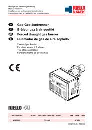
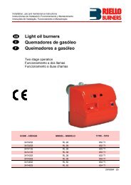
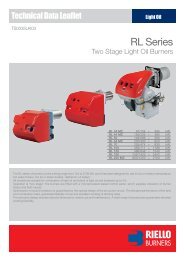
ONE STAGE LIGHT OIL BURNERS<br />
<strong>PRESS</strong> <strong>GV</strong> SERIES<br />
<strong>PRESS</strong> G24 140 ÷ 280 kW<br />
<strong>PRESS</strong> <strong>GV</strong> 178 ÷ 356 kW<br />
The <strong>PRESS</strong> G series of burners covers a firing range from 140 to 356 kW and they have<br />
been designed for use in civil installations of small dimensions or in industrial applications,<br />
like incinerators or dyer kilns.<br />
Operation is “one stage”; the burners are fitted with a microprocessor control panel which<br />
supplies indication of operation and diagnosis of fault cause. The combustion head, that can<br />
be set on the basis of required output, allows optimal performance ensuring good combustion<br />
and reducing fuel consumption.<br />
The main feature of these burners is their reliability due to a simple and strong construction,<br />
which permits operation without particular maintenance intervention.<br />
Simplified maintenance is achieved by the slide bar system, which allows easy access to<br />
all of the essential components of the combustion head. All electrical components are easily<br />
accessible only by dismounting a protection panel, thus guaranteeing a quick and simple<br />
intervention on components.<br />
TS0036UK02
TECHNICAL DATA<br />
Model<br />
<strong>PRESS</strong> G24<br />
<strong>PRESS</strong> <strong>GV</strong><br />
Burner operation mode<br />
One stage<br />
Modulation ratio at max. output<br />
--<br />
Servomotor<br />
run time<br />
Heat output<br />
Working temperature<br />
Net calorific value<br />
type<br />
s<br />
kW<br />
Mcal/h<br />
Kg/h<br />
°C min./max.<br />
kWh/kg<br />
kcal/kg<br />
140 - 280<br />
120 - 241<br />
12 - 24<br />
--<br />
--<br />
0/40<br />
11,86<br />
10.200<br />
178 - 356<br />
153 - 306<br />
15 - 30<br />
Viscosity<br />
mm 2 /s (cSt)<br />
4 ÷ 6 (at 20°C)<br />
Electrical data<br />
Fuel / air data<br />
Pump<br />
delivery<br />
Atomised pressure<br />
Fuel temperature<br />
Fuel pre-heater<br />
Fan<br />
Air temperature<br />
Electrical supply<br />
Auxiliary electrical supply<br />
Control box<br />
Total electrical power<br />
Auxiliary electrical power<br />
Heaters electrical power<br />
Protection level<br />
Pump motor electrical power<br />
Rated pump motor current<br />
Pump motor start up current<br />
Pump motor protection level<br />
Fan motor electrical power<br />
Rated fan motor current<br />
Fan motor start up current<br />
Fan motor protection level<br />
type<br />
kg/h<br />
bar<br />
max. °C<br />
type<br />
max. °C<br />
Ph/Hz/V<br />
Ph/Hz/V<br />
type<br />
kW<br />
kW<br />
kW<br />
IP<br />
kW<br />
A<br />
A<br />
IP<br />
kW<br />
A<br />
A<br />
IP<br />
type<br />
AS 47<br />
31 (at 12 bar)<br />
0,4<br />
0,15<br />
40<br />
0,25<br />
2,1<br />
10<br />
40<br />
12<br />
50<br />
NO<br />
Centrifugal with forward curve blades<br />
60<br />
1/50/230~(±10%)<br />
1/50/230~(±10%)<br />
RMO<br />
--<br />
--<br />
--<br />
--<br />
--<br />
--<br />
AN 67 A<br />
67 (at 12 bar)<br />
0,48<br />
0,23<br />
40<br />
0,25<br />
2,1<br />
10<br />
40<br />
Approval Emissions<br />
Ignition trasformer<br />
Operation<br />
Sound pressure<br />
Sound power<br />
CO emission<br />
Grade of smoke indicator<br />
CxHy emission<br />
NOx emission<br />
Directive<br />
Conforming to<br />
Certification<br />
V1 - V2<br />
I1 - I2<br />
dBA<br />
W<br />
mg/kWh<br />
N° Bacharach<br />
mg/kWh<br />
mg/kWh<br />
220V - 1x8 kV<br />
1,6A - 30 mA<br />
73<br />
--<br />
Intermittent (at least one stop every 24 h)<br />
< 40<br />
< 1<br />
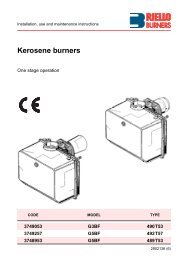
FIRING RATES<br />
35<br />
3,5<br />
30<br />
3,0<br />
<strong>PRESS</strong> G 24<br />
25<br />
2,5<br />
<strong>PRESS</strong> <strong>GV</strong><br />
20<br />
2,0<br />
15<br />
1,5<br />
10<br />
1,0<br />
mm H 2<br />
O<br />
5,0<br />
0<br />
hPa (mbar)<br />
0,5<br />
0<br />
10<br />
15 20 25<br />
30<br />
kg/h<br />
140<br />
175 210 245 280 315 350<br />
kW<br />
Useful working field for choosing the burner<br />
Test conditions conforming to EN 267:<br />
Temperature: 20°C<br />
Pressure: 1000 mbar<br />
Altitude: 100 m a.s.l.<br />
3
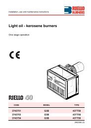
FUEL SUPPLY<br />
HYDRAULIC CIRCUIT<br />
The burners are fitted with a self-priming pump and one (for<br />
<strong>PRESS</strong> <strong>GV</strong>) or two (for <strong>PRESS</strong> G24) delivery valves along<br />
the oil line from the pump to the nozzles.<br />
The pump does not need calibrating, as it is set in the factory<br />
at 12 bar; however, pressure level can be changed if necessary,<br />
by adjusting the regulator fitted on the pump.<br />
The delivery valves control the passage from starting to<br />
operating phase.<br />
For <strong>PRESS</strong> G24, at the start, after pre-purging phase, the first<br />
delivery valve opens and the fuel is sprayed out through the<br />
first nozzle, igniting when it comes into contact with the<br />
spark; then the second delivery valve opens and the fuel is<br />
sprayed out through both nozzles.<br />
V<br />
Example of self-priming pump of <strong>PRESS</strong><br />
<strong>GV</strong> burners<br />
P<br />
Hydraulic layout of <strong>PRESS</strong> G24 burner<br />
Hydraulic layout of <strong>PRESS</strong> <strong>GV</strong> burner<br />
V2<br />
V1<br />
U1<br />
U2<br />
V1<br />
U1<br />
P<br />
P<br />
P<br />
V1<br />
V2<br />
U1<br />
U2<br />
Pump with filter and pressure regulator<br />
1 st delivery valve<br />
2 nd delivery valve<br />
1 st nozzle<br />
2 nd nozzle<br />
4
DIMENSIONING OF THE FUEL SUPPLY LINES<br />
The fuel feed must be completed with the safety devices required by the local norms.<br />
The table shows the choice of piping diameter for the various burners, depending on the difference<br />
in height between the burner and the tank and their distance.<br />
MAXIMUM EQUIVALENT LENGTH FOR THE PIPING L[m]<br />
Model<br />
<strong>PRESS</strong> G24 - <strong>GV</strong><br />
Diameter piping<br />
+H, -H (m)<br />
+4,0<br />
+3,0<br />
+2,0<br />
+1,5<br />
+1,0<br />
+0,5<br />
0<br />
-0,5<br />
-1,0<br />
-1,5<br />
-2,0<br />
-3,0<br />
-4,0<br />
Ø 8 mm<br />
L max (m)<br />
63<br />
55<br />
48<br />
44<br />
40<br />
36<br />
32<br />
28<br />
24<br />
20<br />
16<br />
7<br />
-<br />
Ø 10 mm<br />
L max (m)<br />
130<br />
115<br />
100<br />
92<br />
85<br />
78<br />
70<br />
62<br />
55<br />
48<br />
40<br />
25<br />
10<br />
6<br />
7<br />
10<br />
9 5 V<br />
P<br />
+H<br />
10 cm<br />
8<br />
4<br />
7 5 3<br />
9<br />
2<br />
1<br />
H Difference in height pump-foot valve<br />
Ø Internal pipe diameter<br />
P Height 10 m (max)<br />
V Height 4 m<br />
1 Burner<br />
2 Burner pump<br />
3 Filter<br />
4 Manual shut off valve<br />
5 Suction pipework<br />
6 Bottom valve<br />
7 Remote controlled rapid manual<br />
shut off valve<br />
(compulsory in Italy)<br />
8 Type approved shut off solenoid valve<br />
(compulsory in Italy)<br />
9 Return pipework<br />
10 Check valve<br />
-H<br />
6<br />
note<br />
With ring distribution oil systems, the feasible drawings and dimensioning are the responsibility<br />
of specialised engineering studios, who must check compatibility with the requirements and<br />
features of each single installation.<br />
5
VENTILATION<br />
The ventilation circuit produces low noise<br />
levels with high performance pressure and<br />
air output, in spite of the compact dimensions.<br />
The air damper is easy to set; when fitted, it<br />
makes no difference to air delivery.<br />
Example of fan air gate valve<br />
indexed selector of <strong>PRESS</strong> G24<br />
burner<br />
COMBUSTION HEAD<br />
For the <strong>PRESS</strong> G24 - <strong>GV</strong> series of burners<br />
a special kit for increasing combustion<br />
head length is available.<br />
The choice of using it depends on the thickness of the<br />
front panel and the type of boiler.<br />
Depending on the type of generator, check that the<br />
penetration of the head into the combustion chamber is<br />
correct.<br />
The internal position of the combustion head can easily<br />
be adjusted to the maximum defined output by adjusting<br />
a screw fixed to the flange.<br />
Example of a <strong>PRESS</strong> G24 burner<br />
combustion head<br />
Flame dimensions<br />
Flame lenght (m)<br />
2<br />
1<br />
L max<br />
L min<br />
D max<br />
D min<br />
0 0<br />
0<br />
0,5<br />
1<br />
Burner output (MW)<br />
1<br />
0,5<br />
Flame diameter (m)<br />
L<br />
D<br />
Example:<br />
Burner thermal output = 500 kW;<br />
L flame (m) = 1,3 m (medium value);<br />
D flame (m) = 0,45 m (medium value)<br />
6
ADJUSTMENT<br />
BURNER OPERATION MODE<br />
“One stage” operation<br />
Output Checked Variable<br />
Picture A<br />
°C<br />
bar<br />
ON<br />
OFF<br />
ON<br />
OFF<br />
time<br />
time<br />
The burner of <strong>PRESS</strong> G24 - <strong>GV</strong><br />
series is one stage working.<br />
On “one stage” operation, the<br />
burner adjusts output to the<br />
requested level, by varying<br />
between on-off phases (see<br />
picture A).<br />
All <strong>PRESS</strong> <strong>GV</strong> series burners are fitted with a new microprocessor control panel for the supervision<br />
during intermittent operation.<br />
For helping the commissioning and maintenance work, there are two main elements:<br />
Switc<br />
The lock-out reset button is the central operating element for resetting the burner control<br />
and for activating / deactivating the diagnostic functions.<br />
The multi-color LED is the central indication element for visual diagnosis and interface<br />
diagnosis.<br />
Both elements are located under the transparent cover of lock-out reset button, as showed below.<br />
Switc<br />
There are two diagnostic choices, for indication of operation and diagnosis of fault cause:<br />
- visual diagnosis :<br />
- interface diagnosis :<br />
INTERFACE ADAPTER<br />
COMPUTER<br />
or<br />
by the interface adapter<br />
and a PC with dedicated<br />
software or by a<br />
predisposed flue gas<br />
analyzer (see paragraph<br />
accessories).<br />
FLUE GAS<br />
ANALYSER<br />
7
Indication of operation :<br />
In normal operation, the various statues are<br />
indicated in the form of colour codes according<br />
to the table below.<br />
The interface diagnosis (with adapter) can be<br />
activated by pressing the lock-out button for<br />
> 3 seconds.<br />
Diagnosis of fault causes :<br />
Color code table<br />
Operation statues<br />
Color code table<br />
Stand-by<br />
Pre-purging<br />
Ignition phase<br />
Flame OK<br />
Poor flame<br />
Undervoltage, built-in fuse<br />
Fault, alarm<br />
Extraneous light<br />
LED off<br />
After lock-out has occurred, the red signal lamp is steady on. In this status, the visual fault diagnosis<br />
according to the error code table can be activated by pressing the lock-out reset button for > 3 seconds.<br />
The interface diagnosis (with adapter) can be activated by pressing again the lock-out button for > 3<br />
seconds.<br />
The blinkers of red LED are a signal with this sequence :<br />
(e.g. signal with n° 3 blinks – faulty air pressure monitor)<br />
LED off<br />
3 sec. 3 sec. 3 sec.<br />
Error code table<br />
Possible cause of fault<br />
No establishment of flame at the end of safety time : - faulty or soiled fuel valves<br />
- faulty or soiled flame detector<br />
- poor adjustment of burner, no fuel<br />
- faulty ignition equipment<br />
Faulty air pressure monitor<br />
Extraneous light or simulation of flame on burner start up<br />
Loss of flame during operation : - faulty or soiled fuel valves<br />
- faulty or soiled flame detector<br />
- poor adjustment of burner<br />
Wiring error or internal fault<br />
Blink code<br />
START UP CYCLE<br />
<strong>PRESS</strong> G24<br />
TL<br />
M<br />
1°<br />
13<br />
28<br />
0s<br />
13s<br />
28s<br />
The burner begins the firing cycle;<br />
The motor starts: pre-purge phase;<br />
Ignition electrode sparks.<br />
Delivery valve opens.<br />
The spark goes out;<br />
Start up cycle is concluded.<br />
0<br />
time (s)<br />
<strong>PRESS</strong> <strong>GV</strong><br />
TL<br />
M<br />
1°<br />
2<br />
3<br />
2<br />
25<br />
30<br />
0s<br />
2s<br />
3s<br />
25s<br />
30s<br />
The burner begins the firing cycle.<br />
The motor starts: pre-purge phase.<br />
Ignition electrode sparks.<br />
Delivery valve opens.<br />
The spark goes out; start up cycle is<br />
concluded.<br />
1<br />
0<br />
25<br />
30<br />
0<br />
time (s)<br />
8
WIRING DIAGRAMS<br />
Electrical connections must be made by qualified and skilled<br />
personnel, according to the local norms.<br />
“ONE STAGE” OPERATION<br />
<strong>PRESS</strong> G24<br />
<strong>PRESS</strong> <strong>GV</strong><br />
TB<br />
MB 1 2 3 4 5 6 7 8 9 10 11 12<br />
TS<br />
F<br />
S<br />
1,5 mm 2<br />
PE L N<br />
~50Hz 230V<br />
TL<br />
MB - Burner terminal board<br />
TS - Safety thermostat<br />
S - External lock-out signal<br />
TL - Threshold thermostat<br />
F - Fuse (see table A)<br />
TB - Burner ground (earth) connection<br />
TS<br />
P<br />
MB 1 2 3 4 5<br />
ϑ<br />
6 7<br />
IN<br />
TL PS<br />
ϑ P<br />
F<br />
TB<br />
L N PE<br />
~50Hz 230V<br />
S<br />
MB - Burner terminal board<br />
IN - Manual switch<br />
TS - Safety thermostat<br />
S - External lock-out signal<br />
TL - Threshold thermostat<br />
F - Fuse (see table A)<br />
TB - Burner ground (earth)<br />
connection<br />
PS - Lock-out reset button<br />
The following table shows the supply lead<br />
sections and the type of fuse to be used.<br />
Model<br />
<strong>PRESS</strong> G24<br />
<strong>PRESS</strong> <strong>GV</strong><br />
F<br />
L<br />
A<br />
mm 2<br />
230V<br />
T6<br />
1,5<br />
230V<br />
T6<br />
1,5<br />
Table A<br />
EMISSIONS<br />
mg/kWh<br />
250<br />
200<br />
NO2 EMISSIONS<br />
150<br />
100<br />
50<br />
0<br />
<strong>PRESS</strong> G24<br />
<strong>PRESS</strong> <strong>GV</strong><br />
The emission data has<br />
been measured in the<br />
various models at<br />
maximum output,<br />
according to EN 267<br />
standard.<br />
mg/kWh<br />
50<br />
40<br />
CO EMISSIONS<br />
dB(A)<br />
100<br />
80<br />
NOISE EMISSIONS<br />
30<br />
60<br />
20<br />
40<br />
10<br />
20<br />
0<br />
<strong>PRESS</strong> G24<br />
<strong>PRESS</strong> <strong>GV</strong><br />
0<br />
<strong>PRESS</strong> G24<br />
<strong>PRESS</strong> <strong>GV</strong><br />
9
OVERALL DIMENSIONS (mm)<br />
BURNER<br />
<strong>PRESS</strong> G24<br />
<strong>PRESS</strong> <strong>GV</strong><br />
A<br />
E<br />
F<br />
F (1)<br />
A<br />
E<br />
F<br />
F (1)<br />
H<br />
H<br />
D<br />
I<br />
D<br />
I<br />
B<br />
C<br />
B<br />
C<br />
L<br />
O - O (1)<br />
Model A B C D<br />
E<br />
F<br />
-<br />
F (1)<br />
H<br />
I<br />
L<br />
O<br />
-<br />
O (1)<br />
<strong>PRESS</strong> G24<br />
<strong>PRESS</strong> <strong>GV</strong><br />
425<br />
439<br />
222<br />
234<br />
203<br />
205<br />
397<br />
397<br />
485<br />
473<br />
118<br />
185<br />
-<br />
-<br />
253<br />
320<br />
125<br />
140<br />
290<br />
292<br />
-<br />
59<br />
-<br />
690<br />
-<br />
-<br />
-<br />
825<br />
(1) Length with extended combustion head.<br />
BURNER - BOILER MOUNTING FLANGE<br />
<strong>PRESS</strong> G24<br />
D1<br />
<strong>PRESS</strong> <strong>GV</strong><br />
D1<br />
45°<br />
45°<br />
D3<br />
D4<br />
D2<br />
D5<br />
D3<br />
Ø<br />
D2<br />
Model<br />
<strong>PRESS</strong> G24<br />
<strong>PRESS</strong> <strong>GV</strong><br />
D1<br />
213<br />
160<br />
D2<br />
198<br />
160<br />
D3<br />
160<br />
155<br />
D4<br />
190<br />
-<br />
D5<br />
11<br />
-<br />
Ø<br />
-<br />
M10<br />
PACKAGING<br />
Model X - X (1) Y Z kg<br />
Z<br />
<strong>PRESS</strong> G24<br />
<strong>PRESS</strong> <strong>GV</strong><br />
650<br />
680<br />
535<br />
535<br />
450<br />
450<br />
33<br />
33<br />
X - X (1)<br />
Y<br />
(1) Length with extended combustion head.<br />
10
INSTALLATION DESCRIPTION<br />
Installation, start up and maintenance must be carried out<br />
by qualified and skilled personnel.<br />
All operations must be performed in accordance with the<br />
technical handbook supplied with the burner.<br />
BURNER SETTING<br />
<strong>PRESS</strong> G24<br />
After drilling the boilerplate, using the supplied gasket as a template, fix the flange of burner to<br />
the boiler.<br />
Dismantle the blast tube from the burner and install the nozzles, choosing these on the basis of<br />
the maximum boiler output and following the diagrams included in the burner instruction<br />
handbook.<br />
Check the position of the electrodes.<br />
Adjust the combustion head and refit the blast tube to the burner casing.<br />
Install the burner to the flange.<br />
<strong>PRESS</strong> <strong>GV</strong><br />
The <strong>PRESS</strong> <strong>GV</strong> model has slide bars, for easier installation and maintenance.<br />
After drilling the boilerplate, using the supplied gasket as a template, dismantle the blast tube from<br />
the burner and fix it to the boiler.<br />
Adjust the combustion head.<br />
Refit the burner casing to the slide bars.<br />
Install the nozzle, choosing this on the basis of the maximum boiler output and following the<br />
diagrams included in the burner instruction handbook.<br />
Check the position of the electrodes.<br />
Close the burner, sliding it up to the flange.<br />
HYDRAULIC, ELECTRICAL CONNECTIONS AND START UP<br />
The burners are supplied for connection to two pipes fuel supply system.<br />
Connect the ends of the flexible pipes to the suction and return pipework using the supplied nipples.<br />
Make the electrical connections to the burner following the wiring diagrams included in the<br />
instruction handbook.<br />
Prime the pump by turning the motor.<br />
On start up, check:<br />
- Pressure pump (to max. and min.)<br />
- Combustion quality, in terms of unburned substances and excess air.<br />
11
BURNER ACCESSORIES<br />
Nozzles<br />
The nozzles must be ordered separately. The following table shows<br />
the features and codes on the basis of the maximum required fuel<br />
output.<br />
Nozzles type 60°B<br />
Burner<br />
<strong>PRESS</strong> G24<br />
<strong>PRESS</strong> G24<br />
<strong>PRESS</strong> G24<br />
<strong>PRESS</strong> G24<br />
<strong>PRESS</strong> G24<br />
<strong>PRESS</strong> G24<br />
<strong>PRESS</strong> <strong>GV</strong><br />
<strong>PRESS</strong> <strong>GV</strong><br />
<strong>PRESS</strong> <strong>GV</strong><br />
<strong>PRESS</strong> <strong>GV</strong><br />
<strong>PRESS</strong> <strong>GV</strong><br />
<strong>PRESS</strong> <strong>GV</strong><br />
<strong>PRESS</strong> <strong>GV</strong><br />
<strong>PRESS</strong> <strong>GV</strong><br />
Rated delivery<br />
kg/h (*)<br />
6,3<br />
7,3<br />
8,5<br />
10,6<br />
12,7<br />
14,8<br />
17<br />
19,1<br />
21,2<br />
23,3<br />
25,5<br />
27,6<br />
29,7<br />
31,8<br />
(*) Nozzle rated delivery is referred to atomised pressure<br />
GPH<br />
1,50<br />
1,75<br />
2,00<br />
2,50<br />
3,00<br />
3,50<br />
4,00<br />
4,50<br />
5,00<br />
5,50<br />
6,00<br />
6,50<br />
7,00<br />
7,50<br />
Nozzle<br />
code<br />
3042107<br />
3042110<br />
3042126<br />
3042140<br />
3042158<br />
3042162<br />
3042172<br />
3042182<br />
3042192<br />
3042202<br />
3042212<br />
3042222<br />
3042232<br />
3042242<br />
Extended head kit<br />
“Standard head” burners can be transformed into “extended head” versions, by using the special kit.<br />
The kits available for the various burners, giving the original and the extended lengths, are listed below.<br />
Extended head kit<br />
Burner<br />
<strong>PRESS</strong> G24<br />
‘Standard’ head<br />
length (mm)<br />
118<br />
‘Extended’ head<br />
length (mm)<br />
253<br />
Kit code<br />
3010051<br />
<strong>PRESS</strong> <strong>GV</strong><br />
185<br />
320<br />
3000580<br />
Spacer kit<br />
If burner head penetration into the combustion chamber needs reducing, varying thickness spacers<br />
are available, as given in the following table:<br />
Spacer kit<br />
Burner<br />
<strong>PRESS</strong> <strong>GV</strong><br />
Spacer thickness S (mm)<br />
142<br />
Kit code<br />
3000755<br />
S<br />
12
Sound proofing box<br />
If noise emission needs reducing even further, sound-proofing box is available, as given in the<br />
following table:<br />
Sound proofing box<br />
Burner<br />
<strong>PRESS</strong> <strong>GV</strong><br />
(*) according to EN 15036-1 standard<br />
Box type<br />
Average noise<br />
reduction [dB(A)] (*)<br />
C1/3 10<br />
Box code<br />
3010403<br />
Degasing unit<br />
With single pipe systems, you can find air in the oil sucked by the pump that comes from the oil itself<br />
due to negative pressure or to a faulty seal.<br />
To solve this problem, we recommend fitting a degasing unit near the burner. Two versions are<br />
available with or without filter:<br />
Degasing unit<br />
Burner<br />
Filter<br />
Filtering<br />
degree (μm)<br />
Kit code<br />
<strong>PRESS</strong> <strong>GV</strong><br />
with filter<br />
50 - 75<br />
3010055<br />
<strong>PRESS</strong> <strong>GV</strong><br />
without filter<br />
-<br />
3010054<br />
PC interface kit<br />
To connect the flame control panel to a personal computer for the transmission of operation, fault<br />
signals and detailed service information, an interface adapter with PC software are available.<br />
PC interface kit<br />
Burner<br />
<strong>PRESS</strong> G24 - <strong>GV</strong><br />
Kit code<br />
3002719<br />
13
SPECIFICATION<br />
A specific index guides your choice of burner from<br />
the various models available in the <strong>PRESS</strong> series.<br />
Below is a clear and detailed specification description<br />
of the product.<br />
DESIGNATION OF SERIES<br />
Series :<br />
<strong>PRESS</strong><br />
Operation : <strong>GV</strong> or G24 One stage<br />
GW or 1-2-3-4G Two stage<br />
Emission : ... Class 1 EN267<br />
Head : TC Standard head<br />
TL Extended head<br />
Flame control system :<br />
FS1 Standard (1 stop every 24 h)<br />
FS2 Continuous working (1 stop every 72 h)<br />
Electrical supply to the system :<br />
1/230/50 1/230V/50Hz<br />
1/210/60 1/210V/60Hz<br />
1/220/60 1/220V/60Hz<br />
1/200/50-60 1/200V/50-60Hz<br />
3/230-400/50 3/230V/50Hz - 3N/400V/50Hz<br />
3/210/60 3/210V/60Hz<br />
3/220-380/60 3/220/60Hz - 3N/380V/60Hz<br />
3/200/50-60 3/200V/50-60Hz<br />
Auxiliary voltage :<br />
230/50 230V/50Hz<br />
120/60 120V/60Hz<br />
220/60 220V/60Hz<br />
200/50-60 200V/50-60Hz<br />
<strong>PRESS</strong> G24 TC FS1 1/230/50 230/50<br />
BASIC DESIGNATION<br />
EXTENDED DESIGNATION<br />
AVAILABLE BURNER MODELS<br />
<strong>PRESS</strong> G24 TC FS1 1/230/50 230/50<br />
<strong>PRESS</strong> G24 TC FS1 1/220/60 220/60<br />
<strong>PRESS</strong> <strong>GV</strong> TC FS1 1/200/50-60 200/50-60<br />
<strong>PRESS</strong> <strong>GV</strong> TC FS1 1/230/50 230/50<br />
Other versions are available on request.<br />
14
PRODUCT SPECIFICATION<br />
Burner:<br />
Monoblock forced draught oil burner with one stage operation, fully automatic, made up of:<br />
- Air suction circuit<br />
- Fan with forward curve blades with high performance concerning pressure and air delivery<br />
- Air damper for air setting<br />
- Starting motor at 2850 rpm, single-phase, 230V, 50Hz<br />
- Combustion head, that can be set on the basis of required output, fitted with:<br />
- stainless steel end cone, resistant to corrosion and high temperatures<br />
- ignition electrodes<br />
- flame stability disk<br />
- Gears pump for high pressure fuel supply, fitted with:<br />
- filter<br />
- pressure regulator<br />
- connections for installing a pressure gauge and vacuometer<br />
- internal by-pass for single pipe installation<br />
- Oil valves on the output circuit<br />
- Photocell for flame detection<br />
- Microprocessor based flame control panel, with diagnostic functions<br />
- Slide bars for easier installation and maintenance (for <strong>GV</strong> model)<br />
- Protection filter against radio interference<br />
- IP 44 electric protection level.<br />
Conforming to:<br />
- 89/336/EEC directive (electromagnetic compatibility)<br />
- 73/23/EEC directive (low voltage)<br />
- 92/42/EEC directive (performance)<br />
- 98/37/EEC directive (machinery)<br />
- EN 267 (liquid fuel burners).<br />
Standard equipment:<br />
- 2 flexible pipes for connection to the oil supply network<br />
- 2 gaskets for the flexible pipes<br />
- 2 nipples for connection to the pump<br />
- 2 Pipe fittings (for <strong>GV</strong> model)<br />
- 2 Pipe fittings gasket (for <strong>GV</strong> model)<br />
- 1 burner flange (for G24 model)<br />
- 4 screws for fixing the burner flange to the boiler<br />
- 1 thermal screen<br />
- Instruction handbook for installation, use and maintenance<br />
- Spare parts catalogue.<br />
Available accessories to be ordered separately:<br />
- Nozzles<br />
- Extended head kit<br />
- Spacer kit<br />
- Sound-proofing box (for <strong>GV</strong> model)<br />
- Degasing unit (for <strong>GV</strong> model)<br />
- PC interface kit.<br />
15
Lineagrafica.it<br />
ISO 9001 Cert. n. 0061<br />
RIELLO S.p.A. - Via Ing. Pilade Riello, 5 - 37045 Legnago (VR) Italy<br />
Tel. ++39.0442630111 - Fax ++39.044221980<br />
Internet: http://www.<strong>riello</strong>burners.com - E-mail: info@<strong>riello</strong>burners.com<br />
Since the Company is constantly engaged in the production improvement, the aesthetic and<br />
dimensional features, the technical data, the equipment and the accessories can be changed.<br />
This document contains confidential and proprietary information of RIELLO S.p.A.<br />
Unless authorised, this information shall not be divulged, nor duplicated in whole or in part.