M500 Analog input module
M500 Analog input module
M500 Analog input module

You also want an ePaper? Increase the reach of your titles
YUMPU automatically turns print PDFs into web optimized ePapers that Google loves.
<strong>M500</strong><br />
<strong>Analog</strong> <strong>input</strong> <strong>module</strong><br />
Summary<br />
Applications<br />
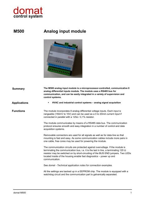
The <strong>M500</strong> analog <strong>input</strong> <strong>module</strong> is a microprocessor-controlled, communicative 8<br />
analog differential <strong>input</strong>s <strong>module</strong>. The <strong>module</strong> uses a RS485 bus for<br />
communication, and can be easily integrated in a variety of supervision and<br />
control systems.<br />
• HVAC and industrial control systems – analog signal acquisition<br />
Functions<br />
The <strong>module</strong> incorporates 8 analog differential voltage <strong>input</strong>s. Each <strong>input</strong> is<br />
rangeable (150mV to 10V) and can be used as a 0 to 20mA current <strong>input</strong> if<br />
connected in parallel with a 125Ω / 0,1% resistor.<br />
The <strong>module</strong> communicates by means of a RS485 data bus. The communication<br />
protocol ensures smooth and easy integration in a number of control and data<br />
acquisition systems.<br />
Removable connectors are used for all signals as well as for data line so that<br />
mounting is fast and easy. As some communication cables include more pairs in<br />
one cable, free cores may be used for powering the <strong>module</strong>.<br />
The communication circuits are protected against overvoltage. If the <strong>module</strong> is<br />
terminating the communication bus, i.e. it is the last in line, a terminating 120 Ω<br />
resistor may be switched on by short-circuiting of the BUS END jumpers. Two LEDs<br />
located inside of the housing enable fast diagnostics – power up and<br />
communication.<br />
See domat - Technical application notes for connection examples.<br />
All the settings are backed up in a EEPROM chip. The <strong>module</strong> is equipped with a<br />
watchdog circuit and the communication part is galvanically separated.<br />
domat <strong>M500</strong> 1
Technical data<br />
Supply voltage<br />
Consumption<br />
10 V ÷ 35 V DC, 14 V ÷ 24 V AC<br />
2000 mW<br />
Working temperature of the <strong>module</strong> 0 ÷ 70°C<br />
Communication<br />
Max. bus length<br />
Max. number of <strong>module</strong>s on the bus<br />
RS485, 1200 ... 19200 bit/s<br />
1200m<br />
256<br />
Number of analog <strong>input</strong>s 8<br />
Input ranges<br />
150mV, 500mV, 1V, 5V, 10V, 20mA<br />
Sampling rate<br />
10 samples/s<br />
Effective resolution<br />
16 bit<br />
Input impedance<br />
>10MΩ<br />
Dimensions<br />
see below<br />
Terminals<br />
Marking<br />
Description<br />
VI1+ to VI8+ „+“ <strong>input</strong> terminals<br />
VI1- to VI8- „-“ <strong>input</strong> terminals<br />
1, 2 power, any polarity<br />
K1+, K1- communication bus<br />
Dimensions<br />
14<br />
8,5<br />
90<br />
45<br />
8,5<br />
14<br />
21,5<br />
53<br />
71 58<br />
10<br />
11/2004 Subject to technical changes.<br />
2 domat <strong>M500</strong>