Mikron M77/78 SeriesMikron M77/78 Series
Mikron M77/78 SeriesMikron M77/78 Series
Mikron M77/78 SeriesMikron M77/78 Series

You also want an ePaper? Increase the reach of your titles
YUMPU automatically turns print PDFs into web optimized ePapers that Google loves.
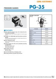
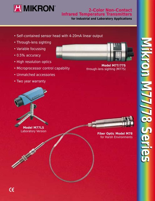
2-Color Non-Contact<br />
Infrared Temperature Transmitters<br />
for Industrial and Laboratory Applications<br />
• Self-contained sensor head with 4-20mA linear output<br />
• Through-lens sighting<br />
• Variable focussing<br />
• 0.5% accuracy<br />
• High resolution optics<br />
• Microprocessor control capability<br />
• Unmatched accessories<br />
• Two year warranty<br />
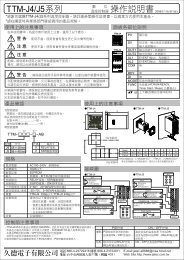
Model <strong>M77</strong>LS<br />
Laboratory Version<br />
Model <strong>M77</strong>/77S<br />
through-lens sighting (<strong>M77</strong>S)<br />
Fiber Optic Model M<strong>78</strong><br />
for Harsh Environments<br />
<strong>Mikron</strong> <strong>M77</strong>/<strong>78</strong> <strong>Series</strong>
<strong>M77</strong>/<strong>78</strong> 2-color Infrared Temperature Transmitters<br />
Innovative Design<br />
The <strong>M77</strong>/<strong>78</strong> series “Infraducers”<br />
represent a milestone in infrared<br />
temperature measurement technology.<br />
They are the first commercially<br />
available, completely self-contained,<br />
2-color radiometers to produce a<br />
4-20mA linear output. The “Infraducers”<br />
represent the latest in<br />
innovative technology, integrating<br />
exclusive advanced electronic design<br />
with optical and mechanical<br />
precision that are the essence of<br />
<strong>Mikron</strong> infrared products. Their<br />
design from concept to finish is<br />
based on simplicity of installation<br />
and maintenance. The <strong>M77</strong>/<strong>78</strong><br />
series, with its matchless array of<br />
accessories, demonstrates <strong>Mikron</strong>’s<br />
continuing leadership in infrared<br />
temperature measuring technology.<br />
Why 2-color<br />
Infrared Thermometry?<br />
The <strong>M77</strong>/<strong>78</strong> series are “state of the<br />
art” instruments designed for the<br />
measurement of temperatures above<br />
250°C (500°F). They utilize the<br />
2-color principle, in which the temperature<br />
measurement is made by<br />
ratioing the radiation intensities of<br />
two adjacent wavelengths rather<br />
than from absolute intensity as with<br />
single band (or single color) instruments.<br />
This design approach<br />
eliminates a number of factors that<br />
degrade the accuracy of conventional<br />
instruments. For example,<br />
temperature measurements with<br />
the <strong>M77</strong>/<strong>78</strong> are:<br />
• Independent of emissivity<br />
• Unaffected by dust and other<br />
contaminants in the field of view<br />
• Independent of target size (can<br />
produce accurate reading with<br />
only 5% of the target area<br />
within field of view)<br />
• Unaffected by moving target<br />
within field of view<br />
• Unaffected by dirty viewing<br />
windows<br />
point of failure in other instruments.<br />
Also, there are no optical<br />
or electronic adjustments to be<br />
made in the field. An invalid signal<br />
LED warns if the target radiation<br />
intensity drops to a level too low<br />
for reliable measurements.<br />
The <strong>M77</strong>S Sensor Head incorporates<br />
a high quality, high precision<br />
variable focus optical system that<br />
provides sharp focussing on the<br />
desired target from about 2” (50mm)<br />
to infinity. Focussing is executed by<br />
turning the focussing knob on the<br />
rear panel of the instrument.<br />
The <strong>M77</strong>S enables precision<br />
pinpointing of small target areas.<br />
The user simply adjusts the instrument<br />
until the desired target is<br />
clear within a reticle.<br />
<strong>M77</strong>LS for Laboratory<br />
& Research Applications<br />
The <strong>M77</strong>LS was specifically designed<br />
for research and laboratory<br />
applications and is readily adaptable<br />
for either tripod or optical<br />
bench use. Its through-lens sighting<br />
and variable focussing features<br />
permit precision pinpointing of the<br />
target area.<br />
M<strong>78</strong> for Inaccessible or<br />
Environmentally Severe<br />
Applications<br />
The fiber optics based M<strong>78</strong><br />
“Infraducer” is recommended for<br />
areas where the following conditions<br />
exist:<br />
A. When direct sighting with the<br />
<strong>M77</strong>S is impossible due to<br />
obstructions. The flexibility<br />
of the fiber optics cable overcomes<br />
this problem.<br />
B. Where RF or EMI interference<br />
is a problem, requiring the<br />
electronics to be placed at a<br />
safe distance from the source<br />
of interference.<br />
C. Where exceptionally high ambient<br />
temperatures exist. Fiber optic<br />
tips and lens assemblies can<br />
withstand temperatures up to<br />
600°F (315°C) without cooling<br />
and up to 1000°F (540°C) with<br />
air cooling.<br />
D. Where corrosive environments<br />
prohibit the use of a conventional<br />
system.<br />
E. In vacuum applications where<br />
sighting through the window<br />
is difficult or impossible, a<br />
fiber optics lens assembly can<br />
be placed inside the vacuum<br />
vessel.<br />
F. When an intrinsically safe IR<br />
temperature transmitter is<br />
mandatory.<br />
G. Environments where nuclear<br />
radiation is present. A<br />
specially designed lens and<br />
fiber optics assembly can withstand<br />
high nuclear radiation<br />
levels.<br />
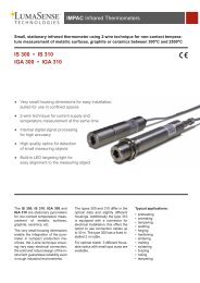
<strong>M77</strong>LS Laboratory Version<br />
<strong>Mikron</strong> 77/77S<br />
for Industrial Applications<br />
The <strong>M77</strong> is housed in a compact,<br />
rugged stainless steel housing only<br />
8” (200mm) long and 2” (50mm) in<br />
diameter. Superior design not only<br />
insures accuracy and long term<br />
reliability, it also guarantees interchangeability<br />
between “Infraducers”<br />
of the same model with ±0.75%<br />
accuracy. This ensures that, should<br />
one of the “Infraducers” need to<br />
be replaced, the replacement unit<br />
would be as accurate as the original<br />
unit. The <strong>M77</strong> has absolutely no<br />
moving parts which are often the<br />
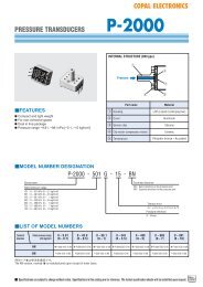
VISUAL SIGHTING<br />
RETICLE DEFINES<br />
EXACT AREA OF<br />
TEMPERATURE<br />
MEASUREMENT<br />
INVALID<br />
READING<br />
EYEPIECE<br />
QUICK<br />
DISCONNECT<br />
CONNECTOR<br />
<strong>M77</strong>LS<br />
REAR<br />
PANEL<br />
SLOPE<br />
ADJUST<br />
FOCUS<br />
2
How to Select an<br />
<strong>M77</strong> Sensor Head<br />
Since there are three <strong>M77</strong> models (<strong>M77</strong>, <strong>M77</strong>S, <strong>M77</strong>LS)<br />
as described on the previous page, it is first necessary to<br />
determine which model you require:<br />
a. <strong>M77</strong> – Fixed focus<br />
b. <strong>M77</strong>S – Variable focus, see through lens<br />
c. <strong>M77</strong>LS – Variable focus, see through lens for<br />
laboratory and research applications.<br />
After choosing the desired model follow these 4 steps.<br />
1. Select the temperature range and units (C or F) from<br />
ranges listed. Insert ranges and units in Box 1 ,<br />
filling in all blanks with zeros.<br />
2. Place letter “R” or “R1” in Box 2 for standard<br />
spectral response.<br />
3. Select signal output; (L) for standard 4-20mA linear,<br />
or (U) for others and insert in Box 3 .<br />
4. Select the correct operating distance.<br />
a. If you selected the <strong>M77</strong> fixed focus model, specify<br />
the desired focus distance in writing (See Table 1.)<br />
and enter “U” in Box 4 .<br />
b. If you selected the focussable <strong>M77</strong>S or <strong>M77</strong>LS<br />
read the section “Optical Resolution” below. Then<br />
choose the desired operating distance and insert the<br />
corresponding Code No. in Box 4 .<br />
EXAMPLE<br />
The model chosen for the instrument indicated in the<br />
selection chart is the focussable <strong>M77</strong>S with through<br />
lens sighting for a temperature range of 800° to 1800°C<br />
with spectral response of two narrow bands, with<br />
4-20mA linear output and a focussable operating<br />
distance of 350mm (14”) to infinity.<br />
Optical Resolution<br />
Three different lenses are available for the <strong>M77</strong>S. The<br />
one you should choose depends on the desired working<br />
distance of the unit. The first version is designed to<br />
measure temperature at distances of 350mm (14”) to<br />
infinity. The second version has a working area of<br />
150mm (6”) to 350mm (14”). The third version is fixed<br />
to measure temperatures at a 50mm (2”) distance.<br />
Proper focussing is achieved by mounting the unit at<br />
the desired distance and adjusting the focussing knob<br />
on the rear panel of the instrument until the target<br />
comes into clear view in the reticle. When the target is<br />
in focus to the eye, it is also in focus to the detector.<br />
Should you wish to move the instrument, remember to<br />
stay within the prescribed working distance, and simply<br />
refocus upon the target after mounting the instrument<br />
in its new location.<br />
A typical field of view diagram is shown below.<br />
Minimum Target size determined by the formula:<br />
Minimum Target Size (d) =<br />
TARGET SIZE (d)<br />
Focussed Distance (D)<br />
Field of View Ratio<br />
DISTANCE (D)<br />
Example: <strong>M77</strong>S, version 1 with 30:1 FOV focussed at<br />
381mm (15”)<br />
D 381<br />
Minimum Target Size(d) = = = 12.7mm<br />
FOV 30<br />
15”<br />
(or = = 0.5”)<br />
30<br />
Selection Chart<br />
<strong>M77</strong>S 0 8 0 0 – 1 8 0 0 C R L<br />
3<br />
1<br />
1 TEMPERATURE RANGE<br />
3<br />
FIELD OF<br />
VIEW RATIO<br />
°C °F<br />
350-800 660-1500<br />
550-1200 1025-2200 15:1<br />
600-1400 1100-2500<br />
400-1000 750-1800<br />
650-1400 1200-2500<br />
30:1<br />
450-1200 850-2200<br />
700-1400 1300-2500<br />
700-1700 1300-3100<br />
700-2000 1300-3600<br />
800-1800 1500-3300<br />
60:1<br />
800-2300 1500-4100<br />
900-1600 1800-3200<br />
500-1400 950-2550<br />
1000-2500 1800-4500<br />
1000-3000 1800-5400<br />
1100-2200 2000-4000 90:1<br />
1200-3200 2200-5800<br />
1200-3500 2200-6500<br />
Notes:<br />
1. Special temperature ranges are available upon request.<br />
2. See table 1 for availability of focus distances for FOV selection.<br />
3. Some 90:1 FOV temperature ranges are also available with a 180:1 FOV.<br />
Please consult <strong>Mikron</strong>.<br />
TABLE 1 – <strong>M77</strong><br />
MINIMUM TARGET<br />
Field of Fixed Focus<br />
View No Sighting<br />
Ratio<br />
15:1 D/15<br />
30:1 D/30<br />
60:1 D/60<br />
90:1 D/90<br />
180:1 D/180<br />
Consult <strong>Mikron</strong><br />
MINIMUM<br />
FOCUS<br />
DISTANCE<br />
2”<br />
2”<br />
6”<br />
6”<br />
14”<br />
Table 2 – <strong>M77</strong>S, <strong>M77</strong>LS Minimum target sizes are<br />
shown in the table below<br />
Field of Version 1 Version 2 Version 3<br />
View Focus 14” Focus 6” Focus at<br />
Ratio to Infinity to 14” 2”<br />
15:1 23.6mm (0.93”) 10.2mm (0.40”) 3.3mm (0.13”)<br />
at 350mm (14”) at 150mm (6”) at 50mm (2”)<br />
30:1 12mm (0.47”) 5mm (0.20”) 1.5mm (0.06”)<br />
at 350mm (14”) at 150mm (6”) at 50mm (2”)<br />
60:1 6mm (0.24”) 2.5mm (0.10”)<br />
at 350mm (14”) at 150mm (6”)<br />
N/A<br />
90:1 4mm (0.16”) 1.8mm (0.07”)<br />
at 350mm (14”) at 150mm (6”)<br />
N/A<br />
2<br />
2 SPECTRAL<br />
RESPONSE<br />
CODE<br />
R1<br />
R<br />
R1<br />
R<br />
R1<br />
TWO<br />
NARROW<br />
BANDS R<br />
NEAR<br />
INFRARED<br />
R1<br />
OUTPUT<br />
4-20mA<br />
Linear<br />
CODE<br />
L<br />
1<br />
3 4<br />
4 OPERATING<br />
DISTANCE<br />
(See note 2)<br />
CODE<br />
350mm<br />
(14”) to 1<br />
infinity<br />
150mm<br />
(6”) to<br />
350mm<br />
(14”)<br />
50mm<br />
(2”) fixed<br />
How to Select an M<strong>78</strong> Sensor Head<br />
The selection process for the M<strong>78</strong> is similar to that of the <strong>M77</strong>, with the<br />
additional requirements of the fiber optic feature. The selection steps are as follows:<br />
1. Select the temperature range and units (C or F) from ranges listed. Insert<br />
ranges and units in Box 1 , filling in all blanks with zeros.<br />
2. Place letter “R” or “R1” in Box 2 for standard spectral response.<br />
3. Select signal output; (L) for standard 4-20mA linear, or (U) for others and<br />
insert in Box 3 .<br />
4. Select the length of fiber optics cable and insert code number in Box 4 .<br />
5. Select the required lens assembly from the field of view diagrams and insert<br />
code number in Box 5 . If, however, an extension tip is to be used, the code<br />
number inserted in Box 5 should be selected from the chart under Rigid<br />
Extension Tip; both stainless steel and ceramic tips are available.<br />
2<br />
3
Selection Chart<br />
C or F<br />
M<strong>78</strong> 0 8 0 0 – 1 8 0 0 C R L<br />
S 1 2 0 3 0 S<br />
1<br />
2 3 4<br />
5 or<br />
1 TEMPERATURE RANGE<br />
See note 1<br />
°C °F<br />
450-1200 850-2200<br />
450-1200 850-2200<br />
500-1400 950-2550<br />
600-1800 1100-3300<br />
700-1400 1300-2500<br />
700-1700 1300-3100<br />
700-2000 1300-3600<br />
800-1800 1500-3300<br />
800-2300 1500-4100<br />
900-1600 1800-3200<br />
1000-2500 1800-4500<br />
1000-3000 1800-5400<br />
1100-2200 2000-4000<br />
1200-3200 2200-5800<br />
1200-3500 2200-6500<br />
FIELD<br />
OF<br />
VIEW<br />
RATIO<br />
3:1<br />
15:1<br />
30:1<br />
30:1<br />
15:1 or<br />
30:1<br />
30:1<br />
90:1<br />
MAX. FIBER<br />
OPTIC<br />
LENGTH<br />
360cm (6’)<br />
360cm (6’)<br />
540cm (6’)<br />
900cm (6’)<br />
For 15:1 –<br />
900cm (30’)<br />
For 30:1 –<br />
180cm (6’)<br />
900cm (30’)<br />
900cm (30’)<br />
See note 4<br />
2 SPECTRAL<br />
RESPONSE<br />
CODE<br />
TWO<br />
NARROW<br />
BANDS<br />
NEAR<br />
INFRARED<br />
R1<br />
R<br />
3 OUTPUT<br />
CODE<br />
4-20mA<br />
L<br />
4 FIBER OPTIC<br />
CABLE<br />
LENGTH<br />
CM FT. CODE<br />
90 3 S03<br />
180 6 S06<br />
360 12 S12<br />
540 18 S18<br />
720 24 S24<br />
900 30 S30<br />
Special Length<br />
– Customer to<br />
Specify Length<br />
in Writing<br />
SXX<br />
5 STANDARD<br />
FOCUS LENS<br />
ASSEMBLY<br />
See note 2<br />
FOV CODE<br />
15:1 015S<br />
30:1 030S<br />
90:1 090S<br />
NON-<br />
STANDARD<br />
FOCUS<br />
See note 3<br />
15:1 015U<br />
5<br />
RIGID<br />
EXTENSION TIPS<br />
See note 5<br />
STAINLESS CERAMIC<br />
STEEL<br />
LENGTH CODE LENGTH CODE<br />
76mm S033 76mm C033<br />
(3’) (3’)<br />
152mm S063 152mm C063<br />
(6’) (6’)<br />
305mm S123 305mm C123<br />
(12’) (12’)<br />
610mm S243 24mm C243<br />
(24’) (24’)<br />
30:1 030U<br />
FOV RATIO<br />
15:1<br />
TARGET DISTANCE IN.<br />
0<br />
Min.<br />
TARGET DIA. IN. 0.4<br />
Focussable<br />
Distance:<br />
5.0cm TARGET DIA. CM<br />
1.0<br />
(2.0”)<br />
TARGET DISTANCE CM<br />
0<br />
30:1<br />
Min.<br />
Focussable<br />
Distance:<br />
12.7cm<br />
(5.0”)<br />
90:1<br />
Min.<br />
Focussable<br />
Distance:<br />
12.7cm<br />
(5.0”)<br />
Standard Lens Assembly<br />
TARGET DISTANCE IN.<br />
TARGET DIA. IN.<br />
0<br />
.40<br />
TARGET DIA. CM<br />
0<br />
TARGET DISTANCE CM<br />
0<br />
0<br />
TARGET DISTANCE IN.<br />
TARGET DIA. IN. .40<br />
TARGET DIA. CM<br />
1.0<br />
TARGET DISTANCE CM<br />
0<br />
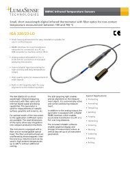
FIELD OF VIEW DIAGRAMS<br />
15<br />
1.0<br />
2.5<br />
38<br />
30<br />
1.0<br />
2.5<br />
76<br />
90<br />
1.0<br />
2.5<br />
230<br />
30<br />
2.4<br />
6.1<br />
76<br />
60<br />
2.5<br />
6.0<br />
150<br />
180<br />
2.5<br />
6.0<br />
460<br />
EXAMPLE<br />
The model number for the M<strong>78</strong> “Infraducer” indicated in the boxes<br />
designates a unit with a temperature range of 800° to 1800°C with a<br />
4-20mA linear output using 360cm (12’) length of fiber optics cable,<br />
a standard lens assembly with an FOV ratio of 30:1 focussed at<br />
760mm (30”).<br />
Notes:<br />
90:1 090U<br />
1. Special ranges are available upon request.<br />
2. All standard focussing distances match their respective FOV<br />
distance, i.e. 30:1 = 30”.<br />
3. When non-standard focus distance is desired, such as close focus,<br />
insert code “U” instead of “S” and describe desired focus distance<br />
in writing.<br />
4. Longer length fiber optic available upon request.<br />
5. All Rigid Extension Tips provide a 3:1 FOV<br />
6. Minimum focus distance for standard lens assembly is 2” for 15:1<br />
FOV and 5” for all others.<br />
7. 6’ fiber cable max. Consult factory for any other configurations.<br />
CLOSE FOCUS FOV*<br />
FOV RATIO 15:1 FOV RATIO 30:1 FOV RATIO 90:1<br />
CODE 015U CODE 030U CODE 090U EXTENSION TIP FIELD OF VIEW (3:1)<br />
D<br />
dø<br />
20°<br />
Tip<br />
*Min Target Size (d) =<br />
Focussed Distance (D)<br />
FOV Ratio 20°<br />
1.5 (.06)<br />
EXTENSION TIP ASSEMBLY<br />
3Ø<br />
(.125)<br />
13<br />
(.50)<br />
64<br />
(2.50)<br />
13<br />
(.50)<br />
19<br />
(.75)<br />
LENGTH<br />
1/2-20 THD 3/4-16 THD<br />
(2) JAM NUTS<br />
LENS ASSEMBLY<br />
All mounting hardware is supplied by <strong>Mikron</strong><br />
114<br />
(4.50)<br />
76<br />
(3.00)<br />
(2) JAM NUTS<br />
STAINLESS STEEL<br />
FLEXIBLE FIBER OPTICS<br />
CABLE (50 (2.00) MIN.<br />
BEND RADIUS)<br />
LENGTH<br />
193<br />
(7.61)<br />
M<strong>78</strong> SENSOR HEAD<br />
51<br />
(2.00)<br />
Four Holes<br />
5 (0.200)<br />
MOUNTING BLOCK<br />
64<br />
(2.50)<br />
25<br />
(1.00)<br />
All dimensions are mm (in.)<br />
4
How to Select an<br />
<strong>M77</strong>E/77EM Electronics<br />
Step No.<br />
A. Insert in box “A” the basic model. Select either<br />
<strong>M77</strong>EM for a single electronics processor or <strong>M77</strong>E<br />
if a complete control package is required.<br />
B. Select the desired control function and insert code<br />
no. in box “B”.<br />
C. Specify the supply voltage and insert code no. in<br />
box “C”.<br />
D. Designate the desired auxiliary code no. in box “D”.<br />
EXAMPLE<br />
An <strong>M77</strong>E electronics with current proportioning 3 mode PID<br />
digital controller with 4-20mA output. Supply voltage of<br />
120VAC with option of automatic tuning.<br />
A<br />
BASIC B CONTROL FUNCTION<br />
MODEL (<strong>M77</strong>E ONLY) CODE<br />
<strong>M77</strong>EM<br />
Processor<br />
<strong>M77</strong>E<br />
Processor/<br />
Controller<br />
A<br />
None<br />
(Mandatory with <strong>M77</strong>EM) 00<br />
Digital Indicator Only<br />
On-Off or Time Proportioning<br />
3 mode indicating controller<br />
Current Proportioning<br />
3 mode controller with 4-20mA output<br />
Position Proportioning<br />
3 mode indicating controller<br />
Time Proportional Duplex<br />
with two time proportioning outputs<br />
Current Proportioning Duplex<br />
with two current proportioning outputs<br />
Current/Relay Duplex<br />
(Relay = Heat)<br />
Current/Relay Duplex<br />
(Relay = Cool)<br />
<strong>M77</strong>E D 9 1 1<br />
C<br />
SUPPLY<br />
VOLTAGE<br />
C<br />
CODE<br />
120VAC 1<br />
240VAC 2<br />
100VAC 3<br />
D<br />
D<br />
B<br />
CONTROL OPTION<br />
NONE (MANDATORY<br />
WITH <strong>M77</strong>EM)<br />
D1<br />
D7<br />
D9<br />
D4<br />
D5<br />
D6<br />
D8<br />
D2<br />
CODE<br />
AUTO TUNE 1<br />
REMOTE SET POINT 2<br />
AUXILIARY OUTPUT 3<br />
RS422<br />
COMMUNICATIONS LINK<br />
DIGITAL INPUT 5<br />
SET POINT RAMP/SOAK<br />
PROGRAMMING<br />
0<br />
4<br />
6<br />
General Specifications<br />
<strong>M77</strong>/<strong>78</strong> Sensor Heads<br />
Accuracy: ±0.5% of full scale for temperature below 3200°F<br />
(1700°C); ±0.75% of full scale for temperature scales above 3200°F<br />
(1700°C)<br />
Resolution: ±0.10% of full scale span (FSS)<br />
Repeatability: ±0.25% of full scale span (FSS)<br />
Output: 4-20mA linear standard<br />
Slope Adjust: Adjustable from .85 to +1.15. Field switchable to<br />
Tungsten Lamp characteristic.<br />
Input Voltage: ±15VDC regulated 200mA min. (External supply<br />
available from <strong>Mikron</strong> 77E/77EM or a separate power supply.)<br />
Load Resistance: 500 ohms max. for 4-20mA<br />
Input Signal Reduction: Up to 95% of reduction in incoming<br />
radiation can be tolerated due to low emissivity, target size<br />
reduction or obscuration for temperature above 1500°F (815°C).<br />
Response Time: 40mS to 10 sec. field adjustable. Response time<br />
defined as time required for output to reach 95% of its final value.<br />
Electrical Connections: Compression type for <strong>M77</strong>, <strong>M77</strong>S and<br />
M<strong>78</strong>. Quick disconnect for <strong>M77</strong>LS.<br />
Operating Ambient Temperature: A) Model <strong>M77</strong> and M<strong>78</strong><br />
sensor head. Without Cooling Jacket: 32 - 120°F (0 - 50°C). With<br />
Cooling Jacket: Up to 600°F (315°C). B) Model M<strong>78</strong> lens and tip<br />
assembly. Without Cooling Jacket: 32 to 600°F (0 to 315°C). With<br />
Cooling Jacket: Up to 900°F (480°C).<br />
Material: Stainless steel.<br />
Weight: 2 lbs. (0.90kg)<br />
Mounting: Support block with four .200” (5mm) dia. holes and<br />
“U” clamp. For more secure mounting use of protective jacket is<br />
recommended.<br />
<strong>M77</strong>/<strong>78</strong>E/EM Electronics<br />
Input Signal Requirements: From <strong>M77</strong> or M<strong>78</strong> of same<br />
tem-perature range 4-20mA (linear)<br />
Slope Adjust: .85 to 1.15<br />
Response Time Adjust: 40mS to 10 sec. Field adjustable.<br />
Peak Picker Decay Rate: (Valley Picker optional) Continuously<br />
adjustable between 0.01 and 10% of full scale/second<br />
Peak Picker Controls: (Valley Picker optional) On, Cancel and<br />
Reset from front panel. Remote Reset actuated by external SPST<br />
switch (customer supplied).<br />
Standard Outputs (Linear): 0-1V Full Scale; 0-50mVDC Full<br />
Scale; 1mV/°F or C; 4-20mADC, 650 ohms max.<br />
Optional Outputs (specify one): In lieu of 0-1VDC or 1mV/°,<br />
0-5VDC full scale; or 0-10VDC full scale<br />
Output Supply Voltage: ±15VDC regulated 200mA min. to power<br />
<strong>M77</strong>/<strong>78</strong> sensor heads<br />
Ambient Temperature Range: 0°C to 50°C (32°F to 120°F)<br />
Size: Front outline <strong>M77</strong>E: 160mm x 128mm (6.5 in. x 5.0 in.) Front<br />
outline <strong>M77</strong>EM: 64mm x 128mm (2.5 in. x 5.0 in.)<br />
Depth Behind Panel: 230mm (9.0 in.)<br />
Panel Cutout: <strong>M77</strong>E: 154mm x 108mm (6.062 in. x 4.25 in.)<br />
<strong>M77</strong>EM: 57.1mm x 108mm (2.25 in. x 4.25 in.)<br />
Electrical Connections: Compression type at rear of instrument<br />
— behind rear cover<br />
Peak Picker Outputs: (Valley Picker optional) All standard<br />
outputs are routed through peak picker.<br />
Electrical Connections: Compression type terminals<br />
Conduit Knockout: 4 holes - 22mm (.875 in.)<br />
Controller (<strong>M77</strong>E only)<br />
Physical Description: Housed in a metal case in a 1/4 DIN<br />
cutout. Modular construction of the plug-in chassis allows easy<br />
access to the controller board and its various option boards. All<br />
power, input, and output wiring are connected to screw terminals<br />
on the rear terminal panel.<br />
Digital Displays: Vacuum fluorescent, alphanumeric. A six digit<br />
display dedicated to the process variable. Alternate information<br />
displayed during configuration mode. An eight digit display shows<br />
key selected operating parameters. Also provides guidance during<br />
controller configuration.<br />
Note 1: Accuracy is stated for targets having grey body<br />
or tungsten lamp characteristics.<br />
Note 2: Certificate of NIST traceability will be provided<br />
upon special request.<br />
5
<strong>M77</strong>EM<br />
<strong>M77</strong>EM CUTOUT<br />
7.84<br />
(200)<br />
6.86<br />
(174)<br />
1.75<br />
(45)<br />
<strong>M77</strong>/<strong>M77</strong>S SENSOR HEAD<br />
INVALID<br />
READING<br />
EYEPIECE<br />
2.00<br />
(51)<br />
SLOPE<br />
ADJUST<br />
FOCUS<br />
OUTPUT<br />
CONNECTOR<br />
5.04<br />
(128)<br />
2.52<br />
(64)<br />
7.75<br />
(198)<br />
1.4<br />
(36)<br />
4.25<br />
(108)<br />
2.12<br />
(54)<br />
1.14<br />
(29) 2.28<br />
(58)<br />
6.62<br />
(168)<br />
.62<br />
(16)<br />
INVALID<br />
READING<br />
2.00<br />
(51)<br />
SLOPE<br />
ADJUST<br />
CONTROLLER<br />
<strong>M77</strong>E<br />
PROCESSOR<br />
<strong>M77</strong>E CUTOUT<br />
4.12<br />
(105)<br />
1.00<br />
(25.4)<br />
1/4 -20<br />
(2) MOUNTING HOLES<br />
<strong>M77</strong>LS SENSOR HEAD<br />
WITH LABORATORY STAND<br />
EYEPIECE<br />
1.50<br />
(38)<br />
2.00<br />
(51)<br />
FOCUS<br />
OUTPUT<br />
CONNECTOR<br />
5.04<br />
(128)<br />
4.250<br />
(108)<br />
2.125<br />
(54)<br />
DIMENSIONS IN INCHES (MILLIMETERS)<br />
6.3<br />
(160)<br />
3.031<br />
(77) 6.067<br />
(154)<br />
Indicators: Alarm Relay Status (ALM 1<br />
or 2), Control Mode (A or MAN), temperature<br />
Units (F or C), Remote Set Point<br />
Active (RSP), Control Relay Status (OUT<br />
1 or 2), Set Point Program RUN or HOLD<br />
(R or H).<br />
Bargraph: 21 segment, color coded<br />
Deviation bargraph —<br />
GREEN = On control<br />
RED = Deviation to ±10% of PV span<br />
Modes of Operation: Manual, Automatic<br />
with local set point, Automatic with<br />
remote set point (2-input units only).<br />
Configurable Parameters and<br />
Setting Range or Selection<br />
(a) Tuning<br />
Gain or PB(%): 0.1 to 999.9<br />
Rate: 0.08 to 10 minutes<br />
Reset: 0.02 to 50.00 minutes/repeat<br />
or repeats/minute<br />
Manual: -100 to 100 (% of Output)<br />
Cycle Time: 1 to 120 seconds<br />
Lockout: None to Maximum<br />
(b) Set Point Ramp<br />
Time: 0 to 255 minutes<br />
Final Set Point: Within the set point<br />
limits<br />
(c) Auto Tune<br />
Step Size: -105 to 105 (% of Output)<br />
(d) Algorithm<br />
Control Algorithm/Output Algorithm:<br />
On-Off, PID-A, PID-B, PD + MR, 3<br />
Position Step/Time Proportional<br />
simplex or duplex, Current Proportional<br />
simplex or duplex, Position<br />
proportional, Current-Relay duplex<br />
(relay = Heat or Cool)<br />
Relay Contact Ratings: Resistive<br />
Load: 5 amperes at 120VAC, 2.5 amperes<br />
at 240VAC. Inductive Load: 50VA at<br />
120VAC or 240VAC<br />
Inputs: 0 to 1VDC from <strong>M77</strong>EM.<br />
A second input provides a remote set<br />
point function and accepts a 4 to 20mA<br />
or a 1 to 5VDC range that can be<br />
characterized.<br />
Control Algorithm: Depending on<br />
the control output type specified, the<br />
controller can be configured for the<br />
following control algorithms: On-Off,<br />
PID-A, PID-B, PD with Manual Reset,<br />
Three Position Step Control<br />
Outputs: The controller is available<br />
with one of the output types listed below:<br />
Time Proportional: Provides On-Off<br />
or Time Proportional (Relay) output.<br />
Current Proportional: Supplies<br />
proportional direct current output for<br />
final control elements which require a<br />
4-20mA signal.<br />
Position Proportional: Positions<br />
a reversible motor with a feedback<br />
slide-wire in proportion to the output<br />
of the control algorithm.<br />
Time Proportional Duplex:<br />
Depending on which control algorithm<br />
you select, can provide On-Off Duplex,<br />
Time Proportional Duplex, or 3 Position<br />
Step Control. The time proportional<br />
duplex output provides independent<br />
PID tuning constants and two time<br />
proportional outputs: one for heat zone<br />
above, and one for the cool zone below<br />
50% output.<br />
Current Proportional Duplex:<br />
Similar to current proportional but<br />
provides a second set of tuning parameters<br />
and a second current output via the<br />
Auxiliary output option, for the heat and<br />
cool zones.<br />
Current Relay Duplex (Relay =<br />
Heat): A variation of Duplex with<br />
Current active for 0 to 50% output<br />
(Tuning Set 2) and Relay active 50<br />
to 100% output (Tuning Set 1).<br />
Current/Relay Duplex (Relay =<br />
Cool): A variation of Duplex with<br />
Current active for 50 to 100% output<br />
and Relay is active for 0 to 50% output.<br />
Configuration: You decide how the<br />
controller is to interact with the process<br />
by selecting, through simple keystrokes,<br />
the functions you want. Internal programs<br />
prompt the operator step-bystep<br />
through the configuration process<br />
assuring quick and accurate entry of all<br />
configurable parameters.<br />
Control Modes: Manual or Automatic<br />
control with bumpless, balanceless<br />
transfer between modes is a standard<br />
feature. In the manual mode, the<br />
6<br />
operator directly controls the controller<br />
output level. In the automatic mode, the<br />
controller will operate from a local set<br />
point, or a remote set point at the second<br />
input.<br />
Alarms: One or two alarm relays are<br />
available to activate external equipment<br />
when preset alarm set points are<br />
reached. Each of the two alarms can<br />
be set to monitor two independent set<br />
points. Each set point can be a high<br />
or low alarm. The alarm type can be<br />
selected to be either of the inputs, the<br />
PV, Deviation, Output, or Shed from the<br />
communications. It can also be used as<br />
an On or Off event at the beginning or<br />
end of a Ramp/Soak segment.<br />
Optional Features<br />
Auto Tune: When enabled, this feature<br />
will automatically calculate and enter<br />
into memory the optimum tuning<br />
parameters required for your process.<br />
A “Short Tune” feature lets you obtain<br />
approximate tuning constants.<br />
Remote Set Point: Isolated high level<br />
input available for remote set point signal.<br />
Auxiliary Output: Can be scaled<br />
from 4-20mA for 0 to 100% for any<br />
range desired. It can be configured<br />
to represent Input 1, Input 2, PV, Set<br />
Point, Deviation, or the Control Output.<br />
Communications: Provides an<br />
RS422 ASCII communication link to a<br />
host computer permitting reading and<br />
writing data transfer type transactions<br />
to the list of configurable parameters.<br />
Digital Input: Allows remote switch<br />
selection of: Local or Remote set point,<br />
Local set point 1 or Local set point 2,<br />
Manual or Automatic control mode, Direct<br />
or Reverse controller action, reset of<br />
Limit Controller, or Run or Hold of<br />
Set Point programming function.<br />
Set Point Ramp/Soak Programming:<br />
Enables you to program and store<br />
6 Ramp and 6 Soak segments for set<br />
point programming. Run or Hold of<br />
program is keyboard or remote switch<br />
selectable.
Support Electronics —<br />
A Complete Process Control Package<br />
<strong>M77</strong> Electronics<br />
Completing the total <strong>M77</strong>/M<strong>78</strong> Infrared Temperature<br />
Measurement System is the auxiliary electronics<br />
module. Two different packages are available, both<br />
of which include a variety of signal outputs.<br />
<strong>M77</strong>EM<br />
Electronics Processor<br />
The <strong>Mikron</strong> 77EM provides remote<br />
adjustment of slope and peak/<br />
valley picker with adjustable decay<br />
rate. Maintenance adjustments,<br />
though not directly exposed, are<br />
easily accessible when needed.<br />
A variety of signal outputs are<br />
provided as standard.<br />
steam or machinery<br />
• When the hottest or coldest temperature of a large<br />
piece is desired<br />
<strong>M77</strong> Control System<br />
The <strong>M77</strong>E Electronics is an integrated system with the<br />
versatility to meet any control application. It is a<br />
combination of the <strong>M77</strong>EM processor and an exceptionally<br />
versatile microprocessor based controller which<br />
offers outstanding features. See pages 5 and 6 for details.<br />
Peak/Valley Picker<br />
The peak/valley picker circuitry<br />
allows a fast system response to<br />
temperature change with adjustable<br />
slow decay of output. This<br />
feature is invaluable in applications where wide temperature<br />
variations are encountered, such as:<br />
• When hot moving objects are separated by cool spaces<br />
between them<br />
• When line of sight of sensor head intermittently or<br />
periodically is obstructed by such things as smoke,<br />
Applications<br />
The unique features of 2-color<br />
infrared thermometry make the <strong>M77</strong>/<strong>78</strong><br />
“Infraducers” ideal for a wide range of<br />
temperature measurement and control<br />
applications above 250°C (500°F). These<br />
include metal melting operations, heat<br />
treating, ore smelting, wire and rod<br />
forming, vacuum furnaces, ceramic kilns,<br />
induction heating and crystal growing.<br />
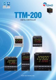
Two applications are illustrated at right.<br />
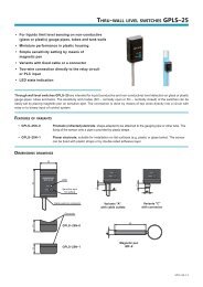
Fig. 1<br />
Fiber Optics<br />
Lens Assembly<br />
M<strong>78</strong><br />
Infraducer<br />
Figure 1:<br />
Induction Heating<br />
The illustration indicates how the M<strong>78</strong>,<br />
with its fiber optic feature, can be used<br />
at multiple locations along the length of<br />
the object being heated to measure the<br />
temperature at critical points to assure<br />
uniformity of treatment.<br />
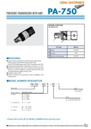
Figure 2:<br />
Vacuum Melting<br />
In vacuum furnaces often sighting through<br />
a window is difficult or undesirable. In<br />
this application a fiber optic lens assembly<br />
is placed inside the vessel, using a vacuum<br />
bushing. Since the M<strong>78</strong> is independent of<br />
emissivity it is also ideal for direct sighting<br />
temperature measurement of molten metal<br />
in other metal furnace applications.<br />
7<br />
Fig. 2<br />
Fiber<br />
Optics<br />
Cable<br />
M<strong>78</strong><br />
Infraducer<br />
Vacuum or<br />
High Pressure<br />
Bushing
Accessories<br />
Protective Jacket<br />
This NEMA 4 rated cast aluminum<br />
jacket and end cap protect the sensor<br />
head from physical damage in heavy<br />
industry environments and dampen<br />
the effect of rapid ambient changes.<br />
The jacket features a quickly removable<br />
end cap which provides easy<br />
access to the eye piece and focussing<br />
knob without disturbing the electrical<br />
connections. In ambients exceeding<br />
the maximum rated temperature of<br />
the sensor head, a protective cooling<br />
jacket is mandatory. While air flow<br />
alone is sufficient for light cooling,<br />
water must be used for moderate and<br />
heavy cooling.<br />
To order: Specify Part No. 11609-7<br />
for protective jacket. Specify Part<br />
No. 11609-8 for protective cooling<br />
jacket.<br />
Air Purge Assembly<br />
This assembly performs two important functions - purging and localized cooling.<br />
Air purging of the optics is extremely important when airborne contaminants can<br />
build up on the lens and eventually “blind” the sensor head.<br />
The <strong>Mikron</strong> air purge assembly has been carefully engineered to prevent<br />
contaminant build up. A flow of only 75 CFH (2 CMH) of normally clean industrial<br />
air will keep the optics clean under most conditions.<br />
The cooling plate section of the air purge assembly allows the coolant to<br />
circulate in a stainless steel chamber which cools the sensor head up to an<br />
ambient temperature of 250°F (120°C) using 10 gallons/hour (38 liters/hour).<br />
To order: Specify Part No. 11524-L.<br />
.50 (13) ø<br />
(4) MOUNTING HOLES EQ. SP.<br />
ON A 4.7500 (121) Ø B.C. 1/8 NPT<br />
COOLANT IN<br />
6.00 ø<br />
(152)<br />
2.31 ø<br />
(59)<br />
3.00<br />
(76)<br />
.45<br />
(11)<br />
1.00<br />
(25)<br />
AIR PURGE ASSY<br />
14.35<br />
(364)<br />
5.60<br />
(142)<br />
1/8 NPT<br />
COOLANT IN<br />
1/8 NPT<br />
COOLANT OUT<br />
3.25<br />
(83)<br />
REMOVABLE CAP<br />
OUTPUT<br />
CABLE<br />
REMOVABLE<br />
CAP<br />
1.90 ø<br />
(48)<br />
2.81 ø<br />
(71)<br />
2.88 ø<br />
(73)<br />
MOUNTING<br />
BRACKET<br />
COOLANT IN<br />
(JACKET)<br />
COOLANT OUT<br />
(ADDITIONAL)<br />
AIR PURGE<br />
ASSEMBLY<br />
SPRING LOADED<br />
AIMING FLANGE<br />
MOUNT<br />
COOLANT<br />
OUT<br />
(JACKET)<br />
PROTECTIVE<br />
COOLING<br />
JACKET<br />
COOLANT IN<br />
(ADDITIONAL)<br />
SIGHT TUBE<br />
AIR<br />
PURGE<br />
IN<br />
NOTES<br />
1. ALL CASTINGS AND FLANGES ARE<br />
ALUMINUM UNLESS OTHERWISE SPECIFIED<br />
2. ALL HARDWARES ARE STAINLESS STEEL<br />
3. ALL DIMENSIONS ARE IN INCHES (MM)<br />
AIR PURGE<br />
SIGHT TUBE<br />
MOUNTING FLANGE<br />
ADJUSTABLE SPRINGS<br />
ANGLE OF<br />
ADJUSTMENT<br />
(X-Y) AXIS<br />
Aiming Flange Assembly<br />
Used in installations requiring mounting of<br />
the sensor assembly while allowing adjustment<br />
of the optical path to a maximum of 5<br />
degrees in any direction.<br />
To order: Specify Part No. 11649-2.<br />
A protective cooling jacket and air purge<br />
assembly for the M<strong>78</strong> fiber optic unit is<br />
shown below.<br />
To order: Specify Part No. 12220-1.<br />
10˚<br />
1/8 NPT AIR<br />
PURGE IN<br />
1/8 NPT<br />
COOLANT OUT<br />
PROTECTIVE JACKET<br />
COOLING (OPTIONAL)<br />
1.94<br />
1.50<br />
(49)<br />
(38) 1/2 NPT<br />
2.50<br />
(63)<br />
OUTPUT CABLE<br />
BUSHING<br />
9.41<br />
(239)<br />
1/4 - 20 TAP X .375 DP.<br />
(2) HOLES<br />
MOUNTING SURFACE<br />
Fiber Optic Target<br />
Illuminator (Optional)<br />
<strong>Mikron</strong> offers a fiber optic illuminator<br />
for precision illumination<br />
of the target areas when used in<br />
conjunction with fiber optics and<br />
lens assembly.<br />
To order: Specify Part No.<br />
12110-1A for 115VAC.<br />
Specify Part No. 12110-2B<br />
for 220VAC.<br />
Power Supplies<br />
A low profile, sealed and rugged package<br />
suitable for chassis mounting. The<br />
front-mounted terminal barrier strip is<br />
perfect for isolation between input and<br />
output voltages. A current limiting feature<br />
protects the power supply when<br />
short circuit occurs. Four tapped holes<br />
are provided for mounting.<br />
Output Voltage: ±15VDC, 300mA max.<br />
Operating Temperature: -15 to 160°<br />
F(-25 to 70° C).<br />
Dimensions: (W x H x D) 2.5” x 1.56”<br />
x 3.5” (64 x 39 x 107mm)<br />
To order: Specify Part No. 11846-6<br />
for 115VAC input. Specify Part No.<br />
11846-7 for 220VAC input.<br />
(48)<br />
AIR<br />
1.9<br />
DIA.<br />
OUT<br />
inches (mm)<br />
1.00<br />
(25)<br />
.40<br />
(10)<br />
COOLANT<br />
OUT<br />
PURGE AIR IN<br />
COOLANT IN<br />
7.81 (198)<br />
PROTECTIVE CAP<br />
FIBER OPTIC CABLE<br />
ADJUSTABLE FLANGE MOUNT (OPTIONAL)<br />
PROTECTIVE<br />
FLEXIBLE HOSE<br />
.50 INSIDE<br />
DIAMETER<br />
(OPTIONAL)<br />
Made in U.S.A. The <strong>M77</strong>/<strong>78</strong> <strong>Series</strong> are designed and manufactured in the U.S.A.<br />
ISO 9001